O
PE
RA
TIN
G I
NS
TR
UC
TIO
NS
Opera
ting I
nstr
uctio
ns
4564 Johnston Parkway, Cleveland, Ohio 44128
P. 800 426 9912 F. 216 518 9884
Sales Inquiries: [email protected]
Technical Support: [email protected]
www.emxinc.com
PRX-320
W A T E R P RO O F P R O X IM ITY C AR D R E A D E R/ K EY P A D
PRX-320 Operating Instructions Template Document no. PRX 320 Instructions rev 1.2.doc REV 1.2 Date 7/13/2018
Product Overview The PRX 320 is a card reader / keypad access control with 2000 card users and 8 passcode
users. Very easy to program with Batch command.
Section Sub Section Title Page
I. Special Features 1
II. Front Panel and Proximity Card 1
III. Installation Procedures 2
IV. Technical Specifications 2
V. Electrical Connections 2
VI. Programming Cards and Functions 3
1. Add Proximity Card(s) 3
2. Delete Proximity Card(s) 4
3. Add / Change User Pass Code 4
4. Door Lock Time Setting 4
5. Door Access Entry Mode 5
6. Batch Registration (Adding Sequential Card
Series)
5
7. Anti-Tamper Output 6
8. Change System Master Code 6
9. Delete User Pass Codes 7
10. Delete All Proximity Cards 7
11. Door Access Using System Code 7
VII. Mounting Instructions 8
1. Steps 1 - 3 8
2. Steps 4 - 6 9
3. Step 7 10
VIII. Suggested Wiring Examples 11
1. Magnetic Lock Fail Secure 11
2. Magnetic Lock Fail Safe 11
3. Forced Entry Normally Closed Relay 12
4. Forced Entry Normally Open Relay 12
IX. Notes, Precautions and Accessories 13
Warranty and Contact Information Back cover
PRX-320 Operating Instructions Template Document no. PRX 320 Instructions rev 1.2.doc REV 1.2 Date 7/13/2018
I. SPECIAL FEATURES 1. Stand alone operation.
2. Front panel power on indicator.
3. Four door opening modes.
ENTRY MODE 1: Enter 4-digit Pass Code only.
ENTRY MODE 2: Proximity Card access only.
ENTRY MODE 3: Proximity Card plus 4-digit Pass Code.
ENTRY MODE 4: Proximity Card or 4-digit Pass Code.
4. Programming Mode is protected by a 4-digit System Pass Code.
5. All Proximity Cards must be registered prior to use.
6. Maximum storage of 2000 cards.
7. Non-volatile memory protects against data loss.
II. FRONT PANEL and PROXIMITY CARD TYPE
1
CARX-20
If programming manual batch mode use the last 6 digits of the first group and the lowest numbered card.
Indicator Lights Function
Green Status Light: Flashes to indicate panel key press. On to indicate Programming Mode.
Off in Normal Mode.
Yellow Status Light: Flashes to indicate unsuccessful access. On when alarm is active.
Status Light Bar: Red - Power on in Normal Mode. Green – Indicates successful access.
Ten Numeric Keys 0-9: Pass Code Entry and Programming Mode.
# Key: Confirmation Key
* Key: Clear or Escape Key
PRX-320 Operating Instructions Template Document no. PRX 320 Instructions rev 1.2.doc REV 1.2 Date 7/13/2018
III. INSTALLATION PROCEDURES
1. Refer to Index for mounting instructions.
2. Do not install Proximity Reader on or near metal objects, this will reduce the
effective read range for card access detection.
3. Install the appropriate connector(s) to meet application requirements. See
examples on pages 10 and 11.
4. Connect the unit to power.
5. The light status bar should turn red and a single beep will sound. If the unit is not
attached to a surface or mounting plate the yellow status light will be on,
indicating an alarm condition. The alarm is caused by the anti-tamper switch on
the back of the unit.
IV. TECHNICAL SPECIFICATIONS
V. CONNECTIONS
2
Power Supply 12 VDC
Power Supply + / - 20%
Current Draw 90mA standby 110mA activated
Housing Material Grey PVC and Metallic keys
Relay Type Form C SPST contact rating 3A @ 12VDC / 110 VAC 0.5A @ 24 VDC
Temperature Range -20°F – 120°F
Connections 8 /6/2 position connectors with 4 inches wire
Activation Indicator Light bar Red power on normal mode Green on successful activation
Environmental IP67 Water tight
Range 5 inches
Size 5in x 2.75in x 1.5 in.
PRX-320 Operating Instructions Template Document no. PRX 320 Instructions rev 1.2.doc REV 1.2 Date 7/13/2018
3
VI. PROGRAMMING CARDS AND FUNCTIONS Default Factory Pass Code is: 4567.
Default Factory Entry mode is: ENTRY MODE 2 (If another Entry Mode is desired proceed
to "Function 5" before entering Proximity Cards or Pass Codes).
To enter into Programming Mode, press the following keys in sequence: *#4567#
After the last # is pressed the unit will "Beep" once and the Green status light will be on.
The system will exit Programming Mode automatically if no keys are pressed within 20
seconds.
The user can exit Programming Mode at any time by pressing the * key.
1. Adding Proximity Card(s)
* # 4 5 6 7 #
*** Placing the proximity card to be entered within the reader’s detection range
instead of manually entering the 6-Digit Card Code can also register single cards.
This feature will only function for individual card entry and not the Batch
Registration (Function 6) mode.
Enter
* # System Code #
Green
Status Light On
Single Beep
Press
1
Single
Beep
Enter 6-digit
Proximity Card Code
Card Code
Failed
3 Beeps
Card Code
Accepted
Single Beep
Next Card
Duplicate
Card
Enter
*
Terminate
Enter
*
Terminate
PRX-320 Operating Instructions Template Document no. PRX 320 Instructions rev 1.2.doc REV 1.2 Date 7/13/2018
Enter
* # System Code #
Green
Status Light On
Single Beep
Press
2
Single
Beep
Enter 6-digit
Proximity Card Code
Card Code
Failed
3 Beeps
Card Code
Deleted
Single Beep
Next Card
Duplicate
Card
Enter
*
Terminate
Enter
*
Terminate
2. Delete Proximity Card(s)
3. Add / User Pass Code
4. Door Lock Time Setting
4
Enter
* # System Code #
Green
Status Light On
Single Beep
Press
3
Single
Beep
Enter Pass Code Location
( 1 - 8 )
Pass Code
Accepted Single Beep
Enter
4-Digit
Pass Code
Enter
*
Terminate
Enter
* # System Code #
Green
Status Light On
Single Beep
Press
4
Single
Beep
Enter 2-Digit Time Duration
( 01 - 99 )
Complete Time
Accepted
Single Beep
Enter
*
Terminate
PRX-320 Operating Instructions Template Document no. PRX 320 Instructions rev 1.2.doc REV 1.2 Date 7/13/2018
5
5. Door Access Entry Mode
ENTRY MODE 1: Enter 4-Digit Pass Code only.
(Enter 4-Digit Pass Code for access)
ENTRY MODE 2: Proximity Card access only.
(Present Proximity Card for access)
ENTRY MODE 3: Proximity Card plus 4-Digit Pass Code
(Present Proximity Card and enter 4-Digit Pass Code within 5 seconds for
access)
ENTRY MODE 4: Proximity Card or 4-Digit Pass Code
(Present Proximity Card or enter 4-Digit Pass Code for access)
6. Batch Registration (Adding Sequential Card Series)
Enter
* # System Code #
Green
Status Light On
Single Beep
Press
5
Single
Beep
Enter Door Entry Mode
( 1 - 4 )
Complete Single
Beep Enter
*
Terminate
Enter
* # System Code #
Green
Status Light On
Single Beep
Press
6
Single
Beep
Enter 6-Digit
Proximity Card Code
Enter Card 4-Digit Quantity
0001 - 2000
Single
Beep 2
Beeps
Enter
* To Terminate
PRX-320 Operating Instructions Template Document no. PRX 320 Instructions rev 1.2.doc REV 1.2 Date 7/13/2018
6
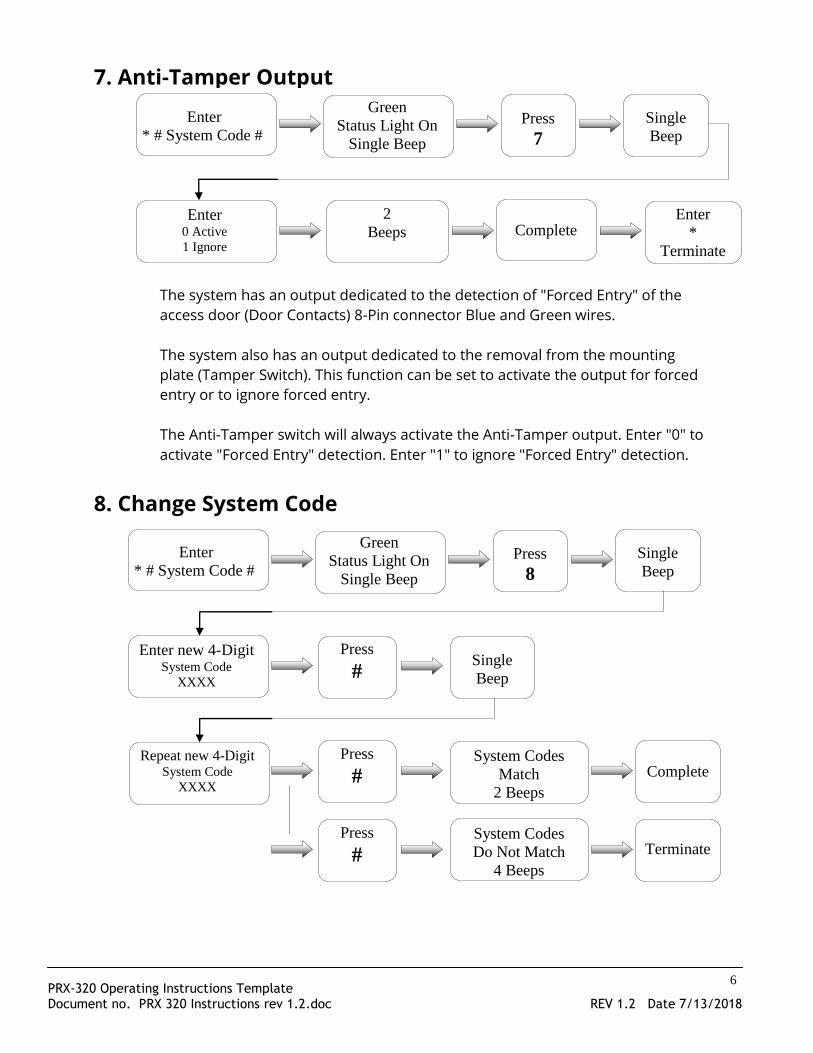
7. Anti-Tamper Output
The system has an output dedicated to the detection of "Forced Entry" of the
access door (Door Contacts) 8-Pin connector Blue and Green wires.
The system also has an output dedicated to the removal from the mounting
plate (Tamper Switch). This function can be set to activate the output for forced
entry or to ignore forced entry.
The Anti-Tamper switch will always activate the Anti-Tamper output. Enter "0" to
activate "Forced Entry" detection. Enter "1" to ignore "Forced Entry" detection.
8. Change System Code
Enter
* # System Code #
Green
Status Light On
Single Beep
Press
7
Single
Beep
Enter 0 Active
1 Ignore
Complete 2
Beeps Enter
*
Terminate
Enter
* # System Code #
Green
Status Light On
Single Beep
Press
8
Single
Beep
Enter new 4-Digit System Code
XXXX
Press
# Single
Beep
Repeat new 4-Digit System Code
XXXX
Press
#
Press
#
System Codes
Match
2 Beeps
System Codes
Do Not Match
4 Beeps
Complete
Terminate
PRX-320 Operating Instructions Template Document no. PRX 320 Instructions rev 1.2.doc REV 1.2 Date 7/13/2018
7
The factory default System Pass Code: 4567
The new 4-Digit System Pass Code value must be entered twice.
9. Delete User Pass Codes
10. Delete All Proximity Cards
11. Door Access Using System Code
Enter
* # System Code #
Green
Status Light On
Single Beep
Press
9
Single
Beep
Press
3
Complete Single
Beep Enter
*
Terminate
This function will delete ALL 8 User Pass Codes
Enter
* # System Code #
Green
Status Light On
Single Beep
Press
9
Single
Beep
Press
9
2
Beeps Green
Status light
is flashing
Complete
This function will delete All Proximity Cards stored in the system. The Green
Status light will flash up to 20 seconds while the function is executing
Enter
* # System Code #
Green
Status Light On
Single Beep
Press
0
Single
Beep
Press
0
Complete Door
Access
PRX-320 Operating Instructions Template Document no. PRX 320 Instructions rev 1.2.doc REV 1.2 Date 7/13/2018
VII. MOUNTING INSTRUCTIONS
8
PRX-320 Operating Instructions Template Document no. PRX 320 Instructions rev 1.2.doc REV 1.2 Date 7/13/2018
9
PRX-320 Operating Instructions Template Document no. PRX 320 Instructions rev 1.2.doc REV 1.2 Date 7/13/2018
10
PRX-320 Operating Instructions Template Document no. PRX 320 Instructions rev 1.2.doc REV 1.2 Date 7/13/2018
11
VIII. SUGGESTED WIRING EXAMPLES
Example 1 Example 2
PRX-320 Operating Instructions Template Document no. PRX 320 Instructions rev 1.2.doc REV 1.2 Date 7/13/2018
12
Example 3
Example 4
PRX-320 Operating Instructions Template Document no. PRX 320 Instructions rev 1.2.doc REV 1.2 Date 7/13/2018
IX. Notes, Precautions and Accessories
Accessories:
13
Notes:
1) The system provides two external relay connection points:
a. "Forced Entry" Anti-damage (Tamper switch and door sensor) alarm output
connection point. (Orange wire 8 pin connector)
b. Duress alarm output connection point. (Yellow wire 8 pin connector)
2) If door sensors are connected, be sure to enable Function 7 (Anti-Tamper Output)
3) The door sensor (Anti-Tamper Output) will activate if the door is not closed within
30 seconds after a valid card or code access.
4) The "Duress" alarm may be activated by pressing the * key before entering 4-Digit
Pass Code
5) Alarms can be cleared by entering the Programming Mode, presenting a valid
Access Card or entering a valid User Pass Code.
Precautions:
1. Prior to installation, check voltage and polarity of the power supply to avoid
damage to the Proximity Reader.
2. Do not share the power supply of the Proximity Reader with an electric lock.
3. Do not install the Proximity Reader on or near metal objects, this will reduce
the effective read range for Access Card detection.
4. Do not attempt any repair or modification of the Proximity Reader.
PRX320-PAD CARX-20
White polypropylene mounting plate Reinforced access card
PRX-320 Operating Instructions Template Document no. PRX 320 Instructions rev 1.2.doc REV 1.2 Date 7/13/2018
4564 Johnston Parkway
Cleveland, Ohio 44128
United States of America
www.emxinc.com
Technical Support: (216) 834-0761
[email protected]
Sales: (216) 518-9888
Fax: (216) 518-9884
[email protected]