4Subsea, Asker, P.O. Box 99, 1378 Norway Doc.no: 5662 PSA Norway State of the art Bonded Flexible Pipes PROJECT Project Number: 2008-4SUB-0189 Project Name: PSA study on bonded flexible pipes Client ref.: R. Hinderaker Customer: PSA Norway DOCUMENT Document Title: State of the art Bonded Flexible Pipes Document Number: 5662 Document Date [dd.mm.yyyy]: 05/03/2009 Document Revision: Rev 2 Reason for issue: For information Confidentiality: RESPONSIBLE Author Svein Are Løtveit Checked Jan Muren Approver Henning Christensen
Transcript
4Subsea, Asker, P.O. Box 99, 1378 Norway
Doc.no: 5662
PSA Norway State of the art Bonded Flexible Pipes
PROJECT
Project Number: 2008-4SUB-0189
Project Name: PSA study on bonded flexible pipes
Client ref.: R. Hinderaker
Customer: PSA Norway
DOCUMENT
Document Title: State of the art Bonded Flexible Pipes
Document Number: 5662
Document Date [dd.mm.yyyy]: 05/03/2009
Document Revision: Rev 2
Reason for issue: For information
Confidentiality:
RESPONSIBLE
Author Svein Are Løtveit
Checked Jan Muren
Approver Henning Christensen
PSA Norway State of the art Bonded Flexible Pipes, 5662,
Page 2 of 56
I Table of content 1 Introduction ........................................................................................................................ 4
PSA Norway State of the art Bonded Flexible Pipes, 5662,
Page 3 of 56
II Abbreviations ACN Acrylo-nitrile
API American Petroleum Institute
FPSO Floating Production Storage and Offloading unit
HSE FSU
Health and Safety Executive (UK) Floating Storage Unit
ITOPF The International Tanker Owners Pollution Federation
LPG Liquefied Petroleum Gas
MBC Marine Breakaway Coupling
MERL Independent research consultants in polymer engineering and material selection
MMS Mineral Management Service (US)
NVC Physical blends of NBR Rubbers with PVC Resin, plasticizers and stabilizers
OCIMF Oil Companies International Marine Forum
OGP The international organisation of Oil and Gas Producers
PSA Petroleum Safety Authority (Norway)
Tg
Glass transition temperature
PSA Norway State of the art Bonded Flexible Pipes, 5662,
Page 4 of 56
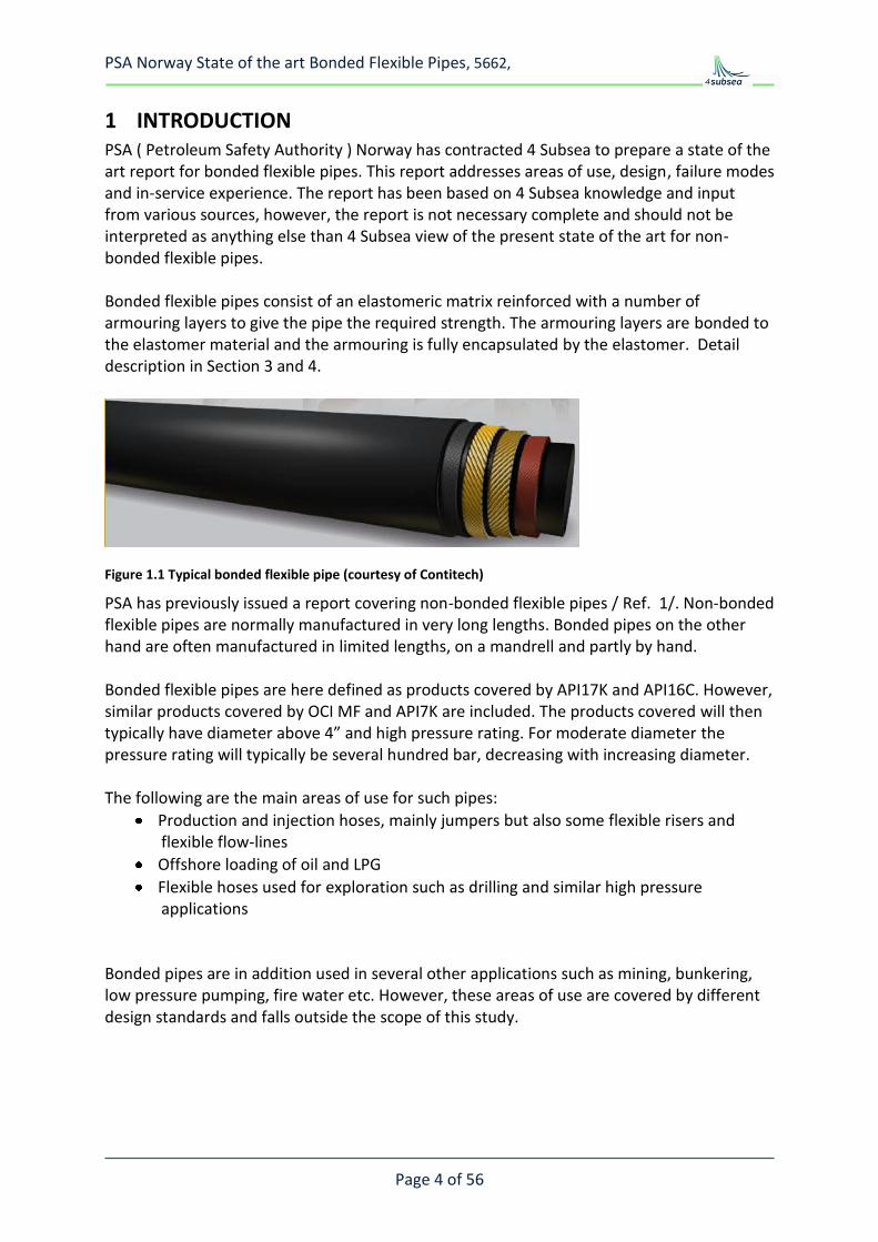
1 INTRODUCTION PSA ( Petroleum Safety Authority ) Norway has contracted 4 Subsea to prepare a state of the art report for bonded flexible pipes. This report addresses areas of use, design, failure modes and in-service experience. The report has been based on 4 Subsea knowledge and input from various sources, however, the report is not necessary complete and should not be interpreted as anything else than 4 Subsea view of the present state of the art for non-bonded flexible pipes. Bonded flexible pipes consist of an elastomeric matrix reinforced with a number of armouring layers to give the pipe the required strength. The armouring layers are bonded to the elastomer material and the armouring is fully encapsulated by the elastomer. Detail description in Section 3 and 4.
Figure 1.1 Typical bonded flexible pipe (courtesy of Contitech)
PSA has previously issued a report covering non-bonded flexible pipes / Ref. 1/. Non-bonded flexible pipes are normally manufactured in very long lengths. Bonded pipes on the other hand are often manufactured in limited lengths, on a mandrell and partly by hand. Bonded flexible pipes are here defined as products covered by API17K and API16C. However, similar products covered by OCI MF and API7K are included. The products covered will then typically have diameter above 4” and high pressure rating. For moderate diameter the pressure rating will typically be several hundred bar, decreasing with increasing diameter. The following are the main areas of use for such pipes:
Production and injection hoses, mainly jumpers but also some flexible risers and flexible flow-lines
Offshore loading of oil and LPG
Flexible hoses used for exploration such as drilling and similar high pressure applications
Bonded pipes are in addition used in several other applications such as mining, bunkering, low pressure pumping, fire water etc. However, these areas of use are covered by different design standards and falls outside the scope of this study.
PSA Norway State of the art Bonded Flexible Pipes, 5662,
Page 5 of 56
2 BACKGROUND
2.1 General
Bonded flexible pipes have several advantages, in particular where short lengths are required, or the space to accommodate the line is tight:
Inherent flexibility of rubber, small bend radius
Short and reliable couplings
Short lengths are produced individually, special requirements can be considered, e.g. special bending stiffness distribution within one section etc.
o Integral bend stiffener at the coupling, if needed extra reinforcement can be added
o Additional layers for fire resistance or external armoring can be added when manufactured
o Built in location collars for floaters or integral floatation can be incorporated
The disadvantages are the following:
Limited length per segment, long lengths will require joints.
Generally lower crush resistance than non-bonded flexibles
Generally lower axial (external) pulling force capability than non-bonded flexibles The in-service experience with bonded flexible pipes used for production of hydrocarbons is mainly related to topside jumpers, drag chain hoses for FPSO turrets and short length riser systems. However, there are a few examples of relatively long length riser application in relatively deep water. Bonded flexible hoses are frequently used for offshore loading of hydrocarbons, such as export oil and LPG. Large bore bonded flexible hoses are standard for offloading of oil, typically 16” to 20”. Short hose sections are joined to long lengths, up to several hundred meters, either as floating hoses, submerged catenary hoses or suspended in air. Such hoses are typically used once a week and stored in the period between. High pressure bonded flexible hoses for exploration are used in the following applications:
- Kill and choke jumpers - Rotary hoses used in the derrick of the drilling rig - Cementing hoses
Such hoses are typically used periodically and inspected and pressure tested before use. The hose pressure rating is the same as for the drilling equipments. Typically 5 ksi(345bar), 10 ksi(690bar) or 15 ksi(1034bar). Experience with hoses used in other industries such as mining, fishing, automotive as well as hoses for bunkering have only partly been considered in this evaluation. The number of brands, the number of services and the often very dedicated functions for these hoses has resulted in different types of challenges and the experience from other industries is only included where it has relevance for bonded hoses for the offshore oil and gas industry.
PSA Norway State of the art Bonded Flexible Pipes, 5662,
Page 6 of 56
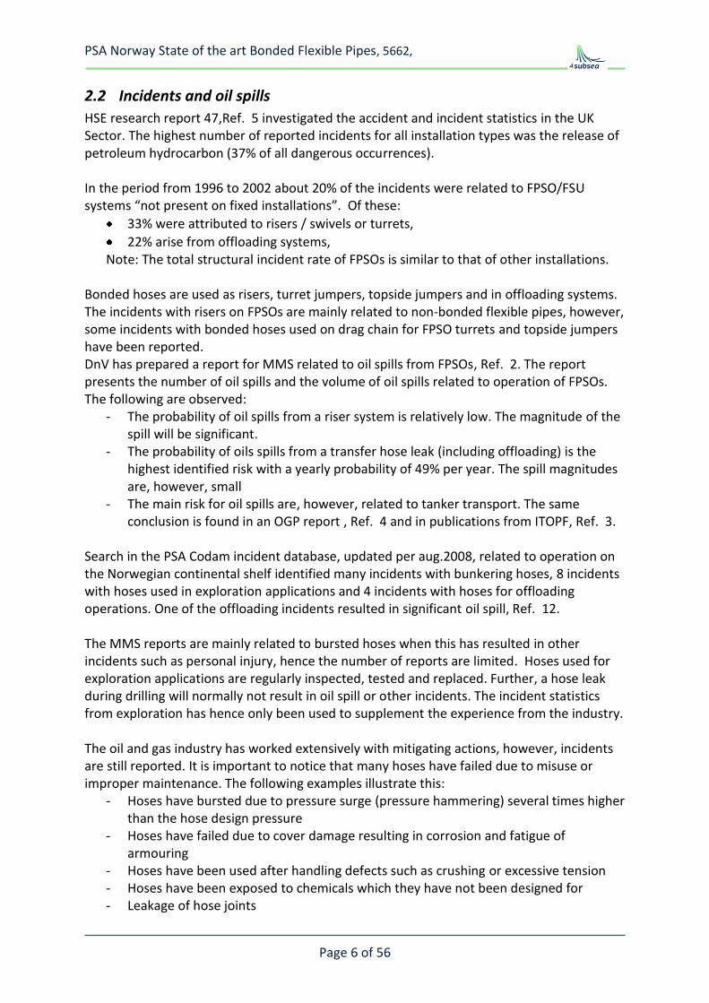
2.2 Incidents and oil spills
HSE research report 47,Ref. 5 investigated the accident and incident statistics in the UK Sector. The highest number of reported incidents for all installation types was the release of petroleum hydrocarbon (37% of all dangerous occurrences). In the period from 1996 to 2002 about 20% of the incidents were related to FPSO/FSU systems “not present on fixed installations”. Of these:
33% were attributed to risers / swivels or turrets,
22% arise from offloading systems, Note: The total structural incident rate of FPSOs is similar to that of other installations.
Bonded hoses are used as risers, turret jumpers, topside jumpers and in offloading systems. The incidents with risers on FPSOs are mainly related to non-bonded flexible pipes, however, some incidents with bonded hoses used on drag chain for FPSO turrets and topside jumpers have been reported. DnV has prepared a report for MMS related to oil spills from FPSOs, Ref. 2. The report presents the number of oil spills and the volume of oil spills related to operation of FPSOs. The following are observed:
- The probability of oil spills from a riser system is relatively low. The magnitude of the spill will be significant.
- The probability of oils spills from a transfer hose leak (including offloading) is the highest identified risk with a yearly probability of 49% per year. The spill magnitudes are, however, small
- The main risk for oil spills are, however, related to tanker transport. The same conclusion is found in an OGP report , Ref. 4 and in publications from ITOPF, Ref. 3.
Search in the PSA Codam incident database, updated per aug.2008, related to operation on the Norwegian continental shelf identified many incidents with bunkering hoses, 8 incidents with hoses used in exploration applications and 4 incidents with hoses for offloading operations. One of the offloading incidents resulted in significant oil spill, Ref. 12. The MMS reports are mainly related to bursted hoses when this has resulted in other incidents such as personal injury, hence the number of reports are limited. Hoses used for exploration applications are regularly inspected, tested and replaced. Further, a hose leak during drilling will normally not result in oil spill or other incidents. The incident statistics from exploration has hence only been used to supplement the experience from the industry. The oil and gas industry has worked extensively with mitigating actions, however, incidents are still reported. It is important to notice that many hoses have failed due to misuse or improper maintenance. The following examples illustrate this:
- Hoses have bursted due to pressure surge (pressure hammering) several times higher than the hose design pressure
- Hoses have failed due to cover damage resulting in corrosion and fatigue of armouring
- Hoses have been used after handling defects such as crushing or excessive tension - Hoses have been exposed to chemicals which they have not been designed for - Leakage of hose joints
PSA Norway State of the art Bonded Flexible Pipes, 5662,
Page 7 of 56
Figure 2.1 OGP reported spill in the North Sea , Ref. 4.
PSA Norway State of the art Bonded Flexible Pipes, 5662,
Page 8 of 56
Figure 2.3 Spill distribution ITOPF, Ref. 3.
2.3 Sources of information
This study has been based on search in the PSA database, information on the internet and direct contacts with selected companies and personnel who were known to have information about bonded flexible pipes. The basis for selection of companies and individuals has been in-house experience in 4Subsea, companies with API approval and telephone meetings with PSA. 4Subsea are grateful for all the valuable information received when compiling this report.
PSA Norway State of the art Bonded Flexible Pipes, 5662,
Page 9 of 56
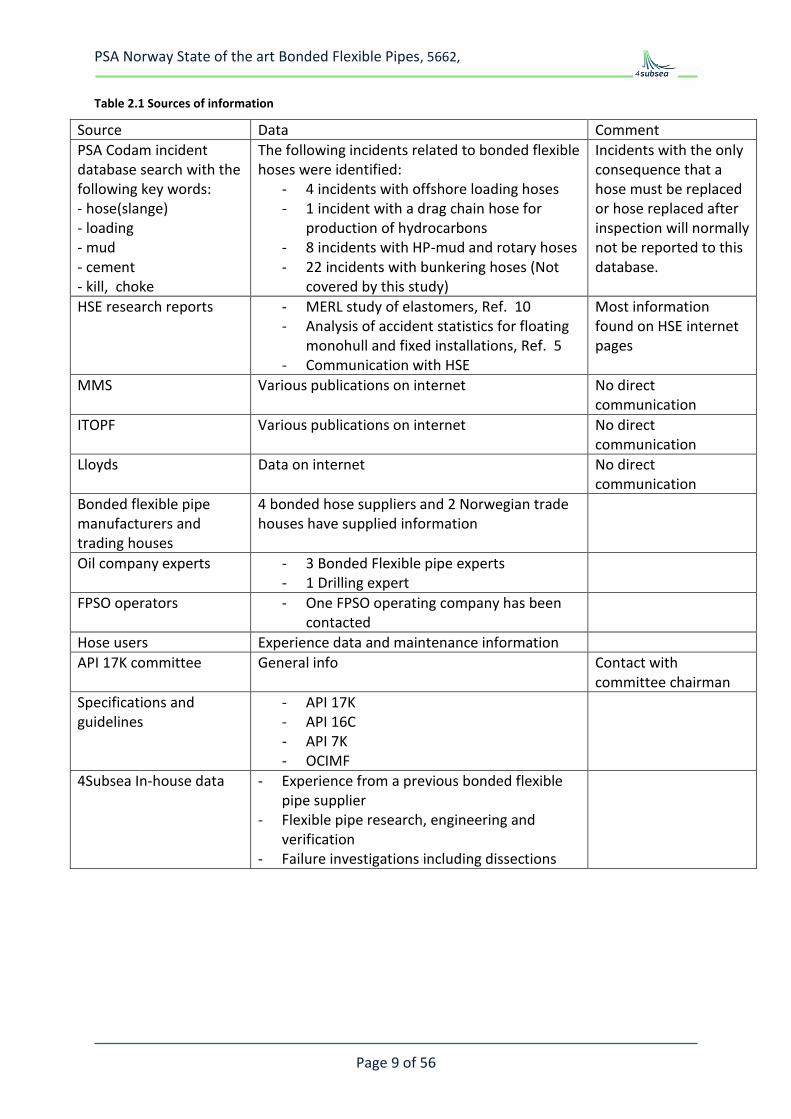
Table 2.1 Sources of information
Source Data Comment
PSA Codam incident database search with the following key words: - hose(slange) - loading - mud - cement - kill, choke
The following incidents related to bonded flexible hoses were identified:
- 4 incidents with offshore loading hoses - 1 incident with a drag chain hose for
production of hydrocarbons - 8 incidents with HP-mud and rotary hoses - 22 incidents with bunkering hoses (Not
covered by this study)
Incidents with the only consequence that a hose must be replaced or hose replaced after inspection will normally not be reported to this database.
HSE research reports - MERL study of elastomers, Ref. 10 - Analysis of accident statistics for floating
monohull and fixed installations, Ref. 5 - Communication with HSE
Most information found on HSE internet pages
MMS Various publications on internet No direct communication
ITOPF Various publications on internet No direct communication
Lloyds Data on internet No direct communication
Bonded flexible pipe manufacturers and trading houses
4 bonded hose suppliers and 2 Norwegian trade houses have supplied information
The API spec 17K approval includes 3rd party approval of design methodology where both pipe capacities and long term integrity is included. In addition the actual approved products are thoroughly tested.
PSA Norway State of the art Bonded Flexible Pipes, 5662,
Page 11 of 56
The bonded flexible risers may be used in similar applications as the non-bonded flexible pipes; however, the following differences should be noted:
Manufacturing in limited length. For long length, pipe joints are required. The length limitations are product dependent and the large bore pipes, 16-24” diameter, are only available in standard lengths of typically 12m. For moderate diameter, 4-10” the length limitation is typically less than 100m. This is short compared to the length limitations for non-bonded flexible pipes which are typically several km.
The bonded pipes use polymer material which bond to the armouring. The polymer material will hence have large shear deformation during bending and combined loads. Only elastomer materials have the required bonding and mechanical properties.
The various elastomer materials have different mechanical, chemical and thermal properties and in addition there is a relatively wide spread of additives used to optimise the material. Each manufacturer has their own proprietary material specifications.
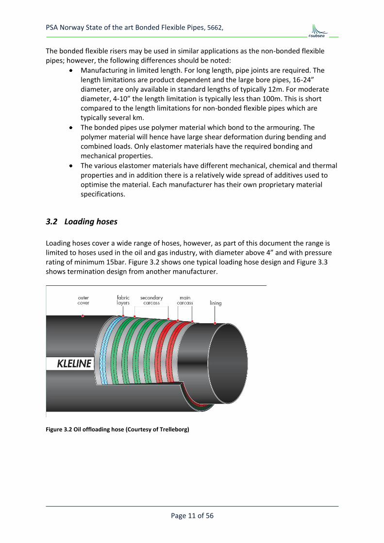
3.2 Loading hoses
Loading hoses cover a wide range of hoses, however, as part of this document the range is limited to hoses used in the oil and gas industry, with diameter above 4” and with pressure rating of minimum 15bar. Figure 3.2 shows one typical loading hose design and Figure 3.3 shows termination design from another manufacturer.
Figure 3.2 Oil offloading hose (Courtesy of Trelleborg)
PSA Norway State of the art Bonded Flexible Pipes, 5662,
Page 12 of 56
Figure 3.3 Single Carcass FEM model. Courtesy of Dunlop Oil & Marine
The loading hoses used in the oil and gas industry are normally based on the OCIMF specification, Ref. 9.
The OCIMF specification is only covering hoses for specific service:
- Offshore loading of oil - Diameter in the range 150 to 600mm - Pressure rating of 15 bar - Crude oil or liquid petroleum products at temp -20oC to 82oC.
The OCIMF specification have specific test requirement which the product has to meet such as pressure tests. However OCIMF requirements related to design methodology, documentation of long term properties or manufacturing are more general than the specific requirements and the 3rd party approval system adopted in API spec 17K. Two manufacturers have offloading hoses approved according to API 17K.
3.3 High pressure hoses used for exploration
Bonded high pressure hoses are frequently used for exploration in the following services:
- Rotary hoses - Kill - Choke - Mud - Cement
PSA Norway State of the art Bonded Flexible Pipes, 5662,
Page 13 of 56
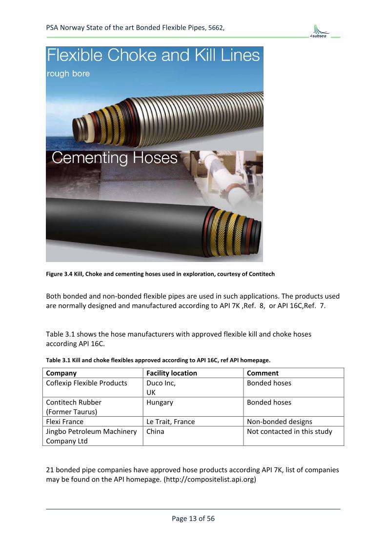
Figure 3.4 Kill, Choke and cementing hoses used in exploration, courtesy of Contitech
Both bonded and non-bonded flexible pipes are used in such applications. The products used are normally designed and manufactured according to API 7K ,Ref. 8, or API 16C,Ref. 7. Table 3.1 shows the hose manufacturers with approved flexible kill and choke hoses according API 16C.
Table 3.1 Kill and choke flexibles approved according to API 16C, ref API homepage.
Company Facility location Comment
Coflexip Flexible Products Duco Inc, UK
Bonded hoses
Contitech Rubber (Former Taurus)
Hungary Bonded hoses
Flexi France Le Trait, France Non-bonded designs
Jingbo Petroleum Machinery Company Ltd
China Not contacted in this study
21 bonded pipe companies have approved hose products according API 7K, list of companies may be found on the API homepage. (http://compositelist.api.org)
PSA Norway State of the art Bonded Flexible Pipes, 5662,
Page 14 of 56
4 DESIGN AND APPLICATIONS
4.1 Bonded hose design
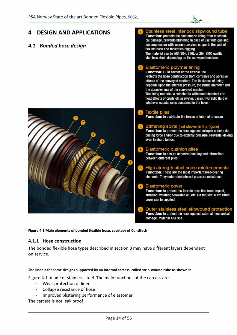
Figure 4.1 Main elements of bonded flexible hose, courtesy of Contitech
4.1.1 Hose construction
The bonded flexible hose types described in section 3 may have different layers dependent on service.
The liner is for some designs supported by an internal carcass, called strip-wound tube as shown in
Figure 4.1, made of stainless steel. The main functions of the carcass are: - Wear protection of liner - Collapse resistance of hose - Improved blistering performance of elastomer
The carcass is not leak proof
PSA Norway State of the art Bonded Flexible Pipes, 5662,
Page 15 of 56
Outside the carcass a leak proof liner is used. The liner will be in contact with the transported fluid and the material must hence be compatible with the fluid. 3 different liners are used in bonded hoses:
- Elastomeric liners which are an integral part of the bonded pipe - H2S resistant synthetic polymer - Corrugated steel tubes, see example in Figure 4.5
Elastomer liners are used for most bonded pipes, the type of elastomer used depends on application. Synthetic polymers are used in special applications in particular for sour service. The corrugated liners are used to prevent that the elastomer is in direct contact with the transported fluid. Outside the liner we have all the reinforcement layers. The reinforcement may consist of helical layers laid at 55 deg. angle only. Such designs will have no pressure induced elongation, however, they will have limited tension capacity. Alternatively the reinforcement layer consists of hoop spirals and helical layers where the hoop spiral gives the pipe hoop strength and the helicals resist the pressure end cap forces and the axial loads. For bonded pipe the helicals are normally made from steel wire ropes or synthetic fibres. The hoop layers are either steel spirals or composite spirals. All the reinforcement layers are prepared with a suitable bonding agent. They are embedded in and bonded to the elastomer in the pipe wall. The reinforcement layers are not in direct contact with the transported fluid, however, diffused fluids must be considered when selecting the material. The outermost elastomer layer is the cover which protects the reinforcement. In some designs fire protection and/or external carcass is used externally of the cover. For offloading pipes buoyancy layers may be applied outside the elastomeric cover. Most high pressure bonded flexible pipes are manufactured by winding rubber and reinforcement outside a rigid cylinder, either a mandrel which is later removed or on a carcass which becomes part of the hose. The hose is constructed by winding the layers one by one. The end fitting mounting is an integrated part of this such that the hose and end-fittings are manufactured into a one piece segments. The hose segment is vulcanised in dedicated chambers with exactly controlled environment. In the vulcanisation process the rubber cross links and bond to the reinforcement and the pipe-wall becomes a solid wall with no voids. Due to the cross linking in the rubber, the pipe wall will not melt but start burning in case of elevated temperature.
PSA Norway State of the art Bonded Flexible Pipes, 5662,
Page 16 of 56
The reinforcement is fully bonded to the rubber material. The rubber material (elastomer) used are selected for the actual service and each of the manufacturers have rubber qualities qualified for their products. Each rubber material consists of a base material with a mix of additives for processing and performance properties.
4.1.2 End fitting design
The end fitting design is an important part of a bonded hose. For most demanding application the end-fitting /coupling is an integral part of the hose which is integrated into the manufacturing process. All the built in couplings are designed stronger than the hose and the hose shall burst before the end-fitting is blown off. For moderate pressure, swaged on couplings are used, ref Figure 4.2. Most couplings are patented by the manufacturers and are special designs for their product range. Figure 4.2, Figure 4.3 and Figure 4.4 show some termination principles: Helical reinforcement layers terminated inside of the end fitting, Figure 4.2:
When the pipe is pressurised the helicals are forced outwards and the grip becomes better and better. Epoxy is used to glue the reinforcement and the end-fitting body
Armours terminated on the outside of the end fitting, Figure 4.3: With this design the helical armours are bonded to the steel end fitting, often with a stiffer and stronger elastomer than used in the flexible part of the hose. Hoop wrapping is normally used outside the helicals to secure the grip.
Integrated terminal, Figure 4.4: Here the steel part of the termination is integrated into the helical reinforcement. With such a design the end termination have no stiff steel structure, this simplify reeling of a jointed pipe length.
PSA Norway State of the art Bonded Flexible Pipes, 5662,
Page 17 of 56
Figure 4.2 Built in and swaged couplings, courtesy of Contitech
Figure 4.3 End fitting, courtesy Dunlop Oil & marine
Figure 4.4 End-fitting, courtesy Trelleborg
PSA Norway State of the art Bonded Flexible Pipes, 5662,
Page 18 of 56
4.2 Design standards
Bonded high pressure flexible pipes have been manufactured in several decades. As an example the bonded hoses from the Hungarian Contitech facility ( Taurus-Emerge) was the standard rotary drilling hose in the Soviet Union, and several countries in Eastern Europe and Asia, resulting in mass production of up to about 150 000 m, more than 10 000 pieces of rotary vibrator and other high pressure hoses per year. The most common sizes in the 70’s and 80’s were 3“ 30 MPa, 4” 30 MPa for the Soviet Union, and 3” 28MPa (Grade C) and 3,5” 34,5 MPa (Grade D) for European and American markets. In addition choke and kill lines and cement hoses up to 69 MPa, grade E (51.7 MPa) rotary hoses, 8” jetting hoses and other so called special hoses were produced. API 7K was introduced as a design standard already in this period, the specification has later been revised. Bonded hoses based on API 7K are still sold in large numbers worldwide, both for onshore and offshore applications. In the 80’s Taurus, Paguag and Dunlop developed new technologies, e.g. to manufacture long-length hoses, hoses for hydrocarbon production and hoses for long term maintenance free operation. This was important for development of bonded hose technology, however, only parts of this resulted in commercial products. The Paguag bonded hose products and the continuous long length Dunlop flexible are examples of products which are no longer manufactured. In 1993 API 16C was introduced as a basis for kill and choke lines and a few manufacturers have obtained approval according to this standard. Finally the introduction of API 17K related to bonded flexible pipes for long term operation has driven the bonded hose technology further and after year 2000 three companies have obtained approval for bonded hoses according to this standard.
Most hose design standards require that the hose is approved for a dedicated service. The hose shall be clearly marked with the manufacturers name, the permissible working pressure and the intended service or the reference standard to which the pipe is designed, ref API 7K/Ref. 8/, API 16C/Ref. 7/ and OCIMF/Ref. 9/.
Most maintenance programs and manufacturers guidance notes to purchasers emphasize that bonded pipe shall not be used outside the service for which they have been designed. Many of the bonded pipes are used in applications where the hoses are relocated frequently and partly considered as consumables. It is important that the hoses are only used for the intended service. The API 7K and API 16C requirements are dedicated for special service and specified pressure rating; the basic requirement is related to the ratio burst pressure to working pressure. Further the standards have requirements securing that the hoses are manufactured according to acceptable quality standards and that the hoses are marked with their intended service including, type of service, pressure rating and temperature rating.
PSA Norway State of the art Bonded Flexible Pipes, 5662,
Page 19 of 56
Most offloading hoses are delivered according to the OCIMF standard. However, several of the offloading hose suppliers contributed to the development of API 17K and two offloading hose supplier has hose designs approved according to API 17K. The following compare bonded flexible pipes approved according to API17K with OCIMF hoses:
- Service life o OCIMF hoses are considered as consumables with a service life of typically 5
years, critical locations may be replaced more often, yearly basis or based on inspection. Service lifer is normally not addressed in detail.
o API 17K approved hoses are normally designed for the entire service life of the system and service life documentation is an important part of the design, including testing and documentation
- Pressure rating o API 17 K hoses are normally designed for higher pressure than 15bar and both
design and normal operation pressure are considered. o OCIMF hoses are normally designed for 15bar pressure rating, the pressure
rating is defined as the maximum pressure to which the hose can be subjected
- Temperature and fluid o OCIMF hoses are designed for a specific service with limitation on both
temperature range and fluid. o API 17K hoses are designed for a service specified by the purchaser. Often
temperature and gas are limiting factors for use of such bonded flexible pipes.
PSA Norway State of the art Bonded Flexible Pipes, 5662,
Page 20 of 56
4.3 Materials
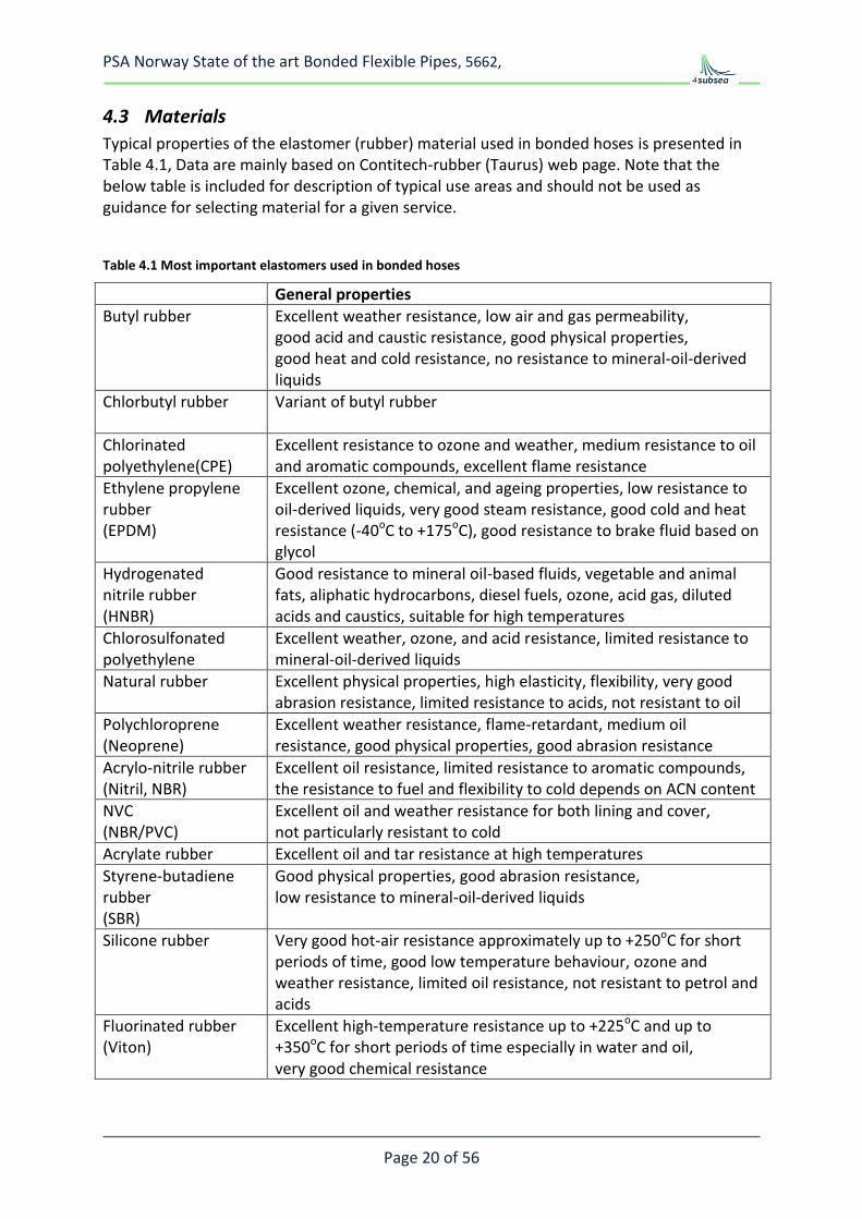
Typical properties of the elastomer (rubber) material used in bonded hoses is presented in Table 4.1, Data are mainly based on Contitech-rubber (Taurus) web page. Note that the below table is included for description of typical use areas and should not be used as guidance for selecting material for a given service.
Table 4.1 Most important elastomers used in bonded hoses
General properties
Butyl rubber
Excellent weather resistance, low air and gas permeability, good acid and caustic resistance, good physical properties, good heat and cold resistance, no resistance to mineral-oil-derived liquids
Chlorbutyl rubber
Variant of butyl rubber
Chlorinated polyethylene(CPE)
Excellent resistance to ozone and weather, medium resistance to oil and aromatic compounds, excellent flame resistance
Ethylene propylene rubber (EPDM)
Excellent ozone, chemical, and ageing properties, low resistance to oil-derived liquids, very good steam resistance, good cold and heat resistance (-40oC to +175oC), good resistance to brake fluid based on glycol
Hydrogenated nitrile rubber (HNBR)
Good resistance to mineral oil-based fluids, vegetable and animal fats, aliphatic hydrocarbons, diesel fuels, ozone, acid gas, diluted acids and caustics, suitable for high temperatures
Chlorosulfonated polyethylene
Excellent weather, ozone, and acid resistance, limited resistance to mineral-oil-derived liquids
Natural rubber
Excellent physical properties, high elasticity, flexibility, very good abrasion resistance, limited resistance to acids, not resistant to oil
Polychloroprene (Neoprene)
Excellent weather resistance, flame-retardant, medium oil resistance, good physical properties, good abrasion resistance
Acrylo-nitrile rubber (Nitril, NBR)
Excellent oil resistance, limited resistance to aromatic compounds, the resistance to fuel and flexibility to cold depends on ACN content
NVC (NBR/PVC)
Excellent oil and weather resistance for both lining and cover, not particularly resistant to cold
Acrylate rubber Excellent oil and tar resistance at high temperatures
Styrene-butadiene rubber (SBR)
Good physical properties, good abrasion resistance, low resistance to mineral-oil-derived liquids
Silicone rubber
Very good hot-air resistance approximately up to +250oC for short periods of time, good low temperature behaviour, ozone and weather resistance, limited oil resistance, not resistant to petrol and acids
Fluorinated rubber (Viton)
Excellent high-temperature resistance up to +225oC and up to +350oC for short periods of time especially in water and oil, very good chemical resistance
PSA Norway State of the art Bonded Flexible Pipes, 5662,
Page 21 of 56
4.4 Application
4.4.1 Bonded flexible risers
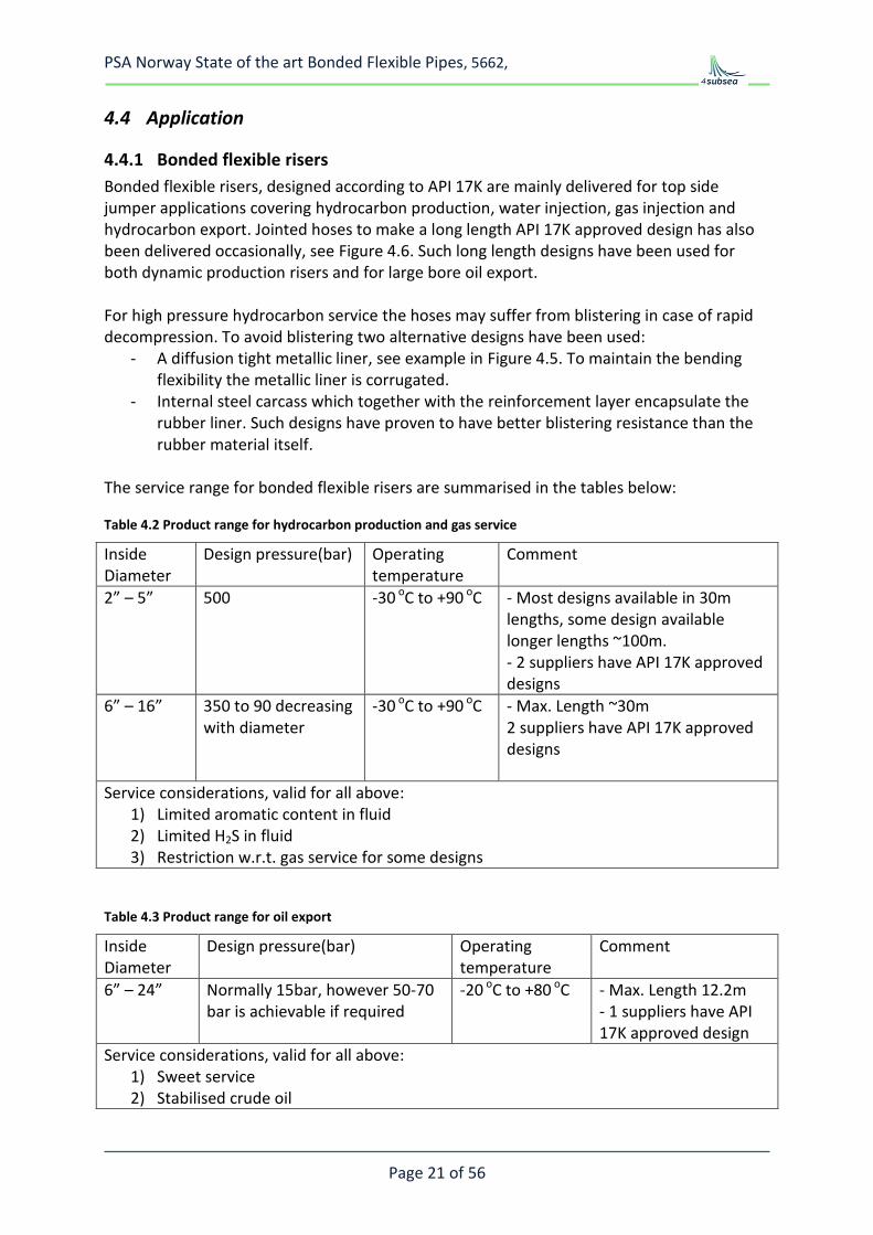
Bonded flexible risers, designed according to API 17K are mainly delivered for top side jumper applications covering hydrocarbon production, water injection, gas injection and hydrocarbon export. Jointed hoses to make a long length API 17K approved design has also been delivered occasionally, see Figure 4.6. Such long length designs have been used for both dynamic production risers and for large bore oil export. For high pressure hydrocarbon service the hoses may suffer from blistering in case of rapid decompression. To avoid blistering two alternative designs have been used:
- A diffusion tight metallic liner, see example in Figure 4.5. To maintain the bending flexibility the metallic liner is corrugated.
- Internal steel carcass which together with the reinforcement layer encapsulate the rubber liner. Such designs have proven to have better blistering resistance than the rubber material itself.
The service range for bonded flexible risers are summarised in the tables below:
Table 4.2 Product range for hydrocarbon production and gas service
Inside Diameter
Design pressure(bar) Operating temperature
Comment
2” – 5” 500 -30 oC to +90 oC - Most designs available in 30m lengths, some design available longer lengths ~100m. - 2 suppliers have API 17K approved designs
6” – 16” 350 to 90 decreasing with diameter
-30 oC to +90 oC - Max. Length ~30m 2 suppliers have API 17K approved designs
Service considerations, valid for all above: 1) Limited aromatic content in fluid 2) Limited H2S in fluid 3) Restriction w.r.t. gas service for some designs
Table 4.3 Product range for oil export
Inside Diameter
Design pressure(bar) Operating temperature
Comment
6” – 24” Normally 15bar, however 50-70 bar is achievable if required
-20 oC to +80 oC - Max. Length 12.2m - 1 suppliers have API 17K approved design
Service considerations, valid for all above: 1) Sweet service 2) Stabilised crude oil
PSA Norway State of the art Bonded Flexible Pipes, 5662,
Page 22 of 56
Figure 4.5 Steel lined hose for gas service, not API 17K approved, courtesy of Copperstate
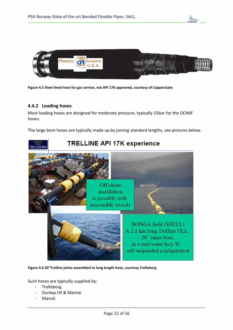
4.4.2 Loading hoses
Most loading hoses are designed for moderate pressure, typically 15bar for the OCIMF hoses. The large bore hoses are typically made up by joining standard lengths, see pictures below.
Figure 4.6 20"Trelline joints assembled to long length hose, courtesy Trelleborg
Such hoses are typically supplied by:
- Trelleborg - Dunlop Oil & Marine - Manuli
PSA Norway State of the art Bonded Flexible Pipes, 5662,
Page 23 of 56
In benign areas such as West of Africa floating hoses are often used, Figure 4.7 and Figure 4.8. In harsh environment submerged catenary configuration are used during loading and the hoses is stored on a reel or on deck between each loading, Figure 4.9.
PSA Norway State of the art Bonded Flexible Pipes, 5662,
Page 24 of 56
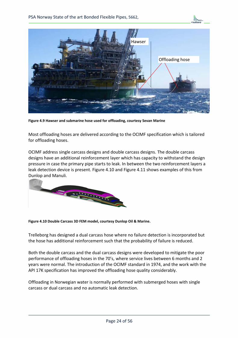
Figure 4.9 Hawser and submarine hose used for offloading, courtesy Sevan Marine
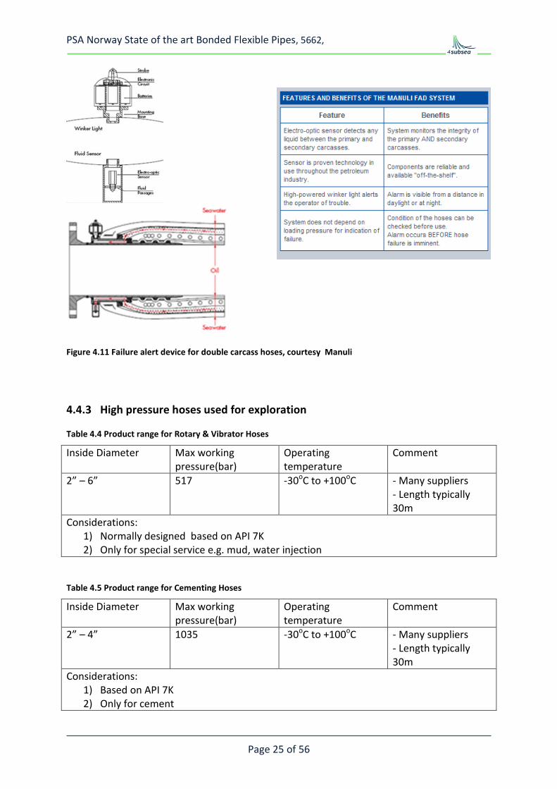
Most offloading hoses are delivered according to the OCIMF specification which is tailored for offloading hoses. OCIMF address single carcass designs and double carcass designs. The double carcass designs have an additional reinforcement layer which has capacity to withstand the design pressure in case the primary pipe starts to leak. In between the two reinforcement layers a leak detection device is present. Figure 4.10 and Figure 4.11 shows examples of this from Dunlop and Manuli.
Figure 4.10 Double Carcass 3D FEM model, courtesy Dunlop Oil & Marine.
Trelleborg has designed a dual carcass hose where no failure detection is incorporated but the hose has additional reinforcement such that the probability of failure is reduced. Both the double carcass and the dual carcass designs were developed to mitigate the poor performance of offloading hoses in the 70’s, where service lives between 6 months and 2 years were normal. The introduction of the OCIMF standard in 1974, and the work with the API 17K specification has improved the offloading hose quality considerably. Offloading in Norwegian water is normally performed with submerged hoses with single carcass or dual carcass and no automatic leak detection.
Hawser
Offloading hose
PSA Norway State of the art Bonded Flexible Pipes, 5662,
Table 4.4 Product range for Rotary & Vibrator Hoses
Inside Diameter Max working pressure(bar)
Operating temperature
Comment
2” – 6” 517 -30oC to +100oC - Many suppliers - Length typically 30m
Considerations: 1) Normally designed based on API 7K 2) Only for special service e.g. mud, water injection
Table 4.5 Product range for Cementing Hoses
Inside Diameter Max working pressure(bar)
Operating temperature
Comment
2” – 4” 1035 -30oC to +100oC - Many suppliers - Length typically 30m
Considerations: 1) Based on API 7K 2) Only for cement
PSA Norway State of the art Bonded Flexible Pipes, 5662,
Page 26 of 56
Table 4.6 Product range for choke and kill Hoses
Inside Diameter Max working pressure(bar)
Operating temperature
Comment
2” – 3” 1035 -30oC to +120oC - 3 suppliers - Length typically 30m
4” 690 -30oC to +120oC - 3 suppliers - Length typically 30m
Considerations: 1) Based on API 16C 2) Sour service and general choke and kill service 3) Smooth bore design and rough bore designs with internal carcass available
5 FAILURE MODE REVIEW
5.1 General
The failure modes for bonded flexible pipes may be grouped in two: - Manufacturing, storage and transport - In service, including handling
Installation which is important for permanent riser systems is here replaced by handling as most of the bonded pipes are connected, disconnected, handled and inspected frequently during their service life.
5.2 Manufacturing, storage and transport
Manufacturing of bonded flexible pipes is to a large extent reliant on good workmanship. The manufacturing involves several operator controlled manufacturing steps covering:
- Elastomer compounding and quality checking - Preparation of mandrel, liner and end-termination before winding - Layer by layer construction of the pipe including fixation to the end-termination and
“built in bend-stiffeners” - Vulcanisation
PSA Norway State of the art Bonded Flexible Pipes, 5662,
Page 27 of 56
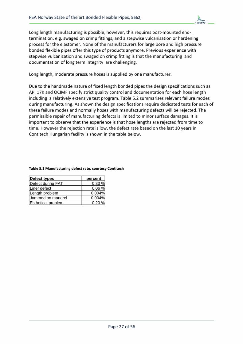
Long length manufacturing is possible, however, this requires post-mounted end-termination, e.g. swaged on crimp fittings, and a stepwise vulcanisation or hardening process for the elastomer. None of the manufacturers for large bore and high pressure bonded flexible pipes offer this type of products anymore. Previous experience with stepwise vulcanization and swaged on crimp fitting is that the manufacturing and documentation of long term integrity are challenging. Long length, moderate pressure hoses is supplied by one manufacturer. Due to the handmade nature of fixed length bonded pipes the design specifications such as API 17K and OCIMF specify strict quality control and documentation for each hose length including a relatively extensive test program. Table 5.2 summarises relevant failure modes during manufacturing. As shown the design specifications require dedicated tests for each of these failure modes and normally hoses with manufacturing defects will be rejected. The permissible repair of manufacturing defects is limited to minor surface damages. It is important to observe that the experience is that hose lengths are rejected from time to time. However the rejection rate is low, the defect rate based on the last 10 years in Contitech Hungarian facility is shown in the table below.
Defect types percent Defect during FAT 0,33 % Liner defect 0,06 % Length problem 0,004% Jammed on mandrel 0,004% Esthetical problem 0,20 %
PSA Norway State of the art Bonded Flexible Pipes, 5662,
Page 28 of 56
Table 5.2 Bonded hose failure modes during manufacturing
Failure mode Description and experience Comment
Bonding failure of elastomer to steel and reinforcement fabric
Bonded pipes rely on proper bonding of the elastomer to both the end termination and the reinforcement layers. Bonding failure has resulted in end fitting being blown off the hose during pressure testing. Leakage and sweating has also caused rejection. Bonding failure between the armour layers will normally only be identified by dissection. Rejection of pipes due to vacuum testing is only relevant for hoses with elastomer liner. Kerosene tests and cyclic gas decompression tests for high pressure gas applications has resulted in hose rejection due to blistering and/or de-bonding.
API 17K and OCIMF have requirements to: - Material documentation and
handling - Surface preparation and
bonding agents - Manufacturing details for
each hose length - Adhesion testing for each
batch of material and between every tenth hose length
- Hydrostatic pressure test of each hose length
- Vacuum test of each hose length
- Kerosene test if specified by purchaser for each hose length
Liner leak A leaking liner will result in pressure build up in the pipe wall. Pressure testing will normally detect such defects.
Example in Figure 5.2 below
Surface damages
Rejection of hose lengths occur from time to time OCIMF and API 17K specify requirements to surface damages: - Generally speaking liner
repair is not permitted. - Minor repair of outer cover is
permitted with an approved procedure
Example in Figure 5.3.
Damages due to improper handling or storage
All bonded hoses are delivered with storage, maintenance and handling recommendations. Provided these are followed the experience is that failure due to improper handling and storage is not a problem. On the other hand improper handling has resulted in failures such as kinking and crushing.
General requirements in the specifications is that the hose shall be stored and handled according to manufacturers specifications
PSA Norway State of the art Bonded Flexible Pipes, 5662,
Page 29 of 56
Figure 5.1 Bonding defect near end fitting detected in pressure test, courtesy of Contitech
Figure 5.2 Pressure test with leaking liner, courtesy of Contitech
PSA Norway State of the art Bonded Flexible Pipes, 5662,
Page 30 of 56
Figure 5.3 Cover damage example, courtesy of Contitech
5.3 In-service and handling failure modes
5.3.1 External damage and wear
For loading hoses this is the most frequent failure mode. - Figure 5.4 shows an example of a propeller cut in a floating hose used for offloading. - Wear and over-bending of loading hoses is frequently reported where the hose is in
contact with the tanker, Figure 5.5. Dedicated hose sections are used in such areas and these sections are inspected and replaced more frequently than the rest of a loading hose.
Figure 5.4 Propeller cut in floating hose (courtesy of Trelleborg)
PSA Norway State of the art Bonded Flexible Pipes, 5662,
Page 31 of 56
For bonded hoses used for exploration the experience seems to be that wear and surface damages occur and that the hoses are replaced before the hose integrity is compromised. One incident reported to MMS with a hose burst during restart of an operation may have been related to reduced hose strength after long term use and wear. Normally exploration hoses that are worn or damaged such that the armouring is exposed are replaced, Ref. figure 5.7. However, bonded hoses are very tough and with proper use long term service life is possible even in rough applications, figure 5.6.
PSA Norway State of the art Bonded Flexible Pipes, 5662,
Page 32 of 56
Figure 5.6 Old rotary hose, manufactured 1994, photo 2003 , courtesy of Contitech
For production jumpers the bonded hoses are permanently connected and if properly designed, wear and external damage should be controlled. However, in certain applications wear and contact with other structures is unavoidable, e.g. drag chain jumpers used on turret moored FPSOs. Drag chain systems with large bore and high pressure flexible pipes have experienced problems and such designs are not that frequently used anymore.
Figure 5.7 Excessive cover damage, courtesy of Contitech
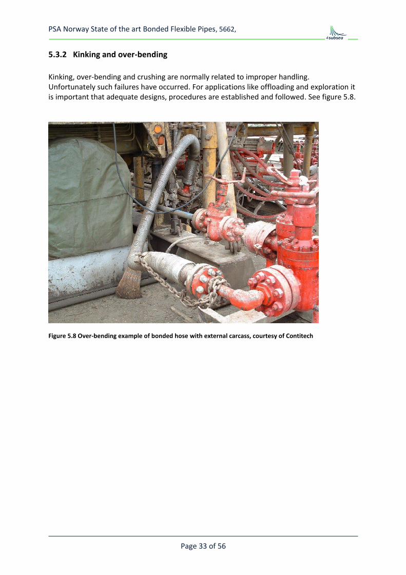
Several bonded hose suppliers offer designs with an external carcass protecting the hose, Figure 5.8 shows an example.
PSA Norway State of the art Bonded Flexible Pipes, 5662,
Page 33 of 56
5.3.2 Kinking and over-bending
Kinking, over-bending and crushing are normally related to improper handling. Unfortunately such failures have occurred. For applications like offloading and exploration it is important that adequate designs, procedures are established and followed. See figure 5.8.
Figure 5.8 Over-bending example of bonded hose with external carcass, courtesy of Contitech
PSA Norway State of the art Bonded Flexible Pipes, 5662,
Page 34 of 56
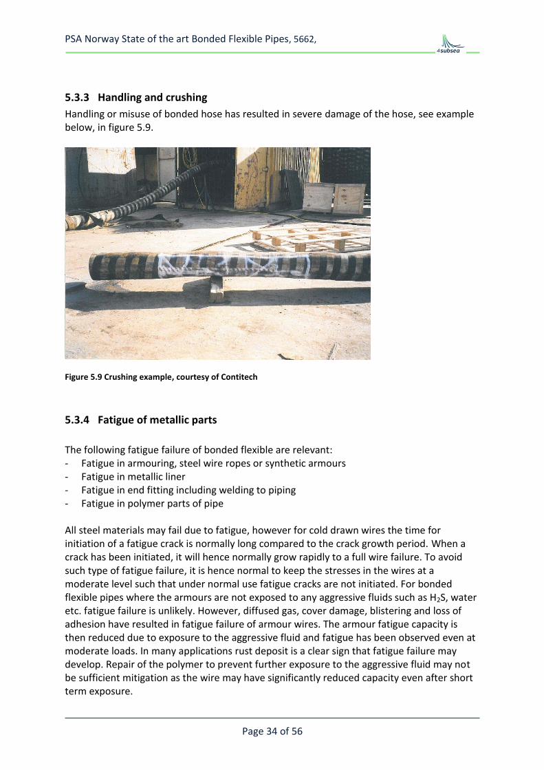
5.3.3 Handling and crushing
Handling or misuse of bonded hose has resulted in severe damage of the hose, see example below, in figure 5.9.
Figure 5.9 Crushing example, courtesy of Contitech
5.3.4 Fatigue of metallic parts
The following fatigue failure of bonded flexible are relevant: - Fatigue in armouring, steel wire ropes or synthetic armours - Fatigue in metallic liner - Fatigue in end fitting including welding to piping - Fatigue in polymer parts of pipe All steel materials may fail due to fatigue, however for cold drawn wires the time for initiation of a fatigue crack is normally long compared to the crack growth period. When a crack has been initiated, it will hence normally grow rapidly to a full wire failure. To avoid such type of fatigue failure, it is hence normal to keep the stresses in the wires at a moderate level such that under normal use fatigue cracks are not initiated. For bonded flexible pipes where the armours are not exposed to any aggressive fluids such as H2S, water etc. fatigue failure is unlikely. However, diffused gas, cover damage, blistering and loss of adhesion have resulted in fatigue failure of armour wires. The armour fatigue capacity is then reduced due to exposure to the aggressive fluid and fatigue has been observed even at moderate loads. In many applications rust deposit is a clear sign that fatigue failure may develop. Repair of the polymer to prevent further exposure to the aggressive fluid may not be sufficient mitigation as the wire may have significantly reduced capacity even after short term exposure.
PSA Norway State of the art Bonded Flexible Pipes, 5662,
Page 35 of 56
Fatigue in metallic liners has been experienced. There are two different metallic liners used; gas tight corrugated pipes (bellows) and open carcass. For corrugated pipes the following fatigue failure modes has been observed: - Fatigue in the weld connecting the corrugated liner to the end-fitting - Torsional induced failure, unclear if the failure is fatigue or repeated yielding due to
torsional un-balance of the armouring - Bending induced fatigue of the corrugated pipe has been observed in dynamic tests For carcasses the consequence of a fatigue crack is normally insignificant as most reported carcass fatigue crack has been observed in the circumferential direction. Such cracks will normally not compromise the carcass function. However, combined with wear and or corrosion the structural capacity of the carcass may be reduced and eventually the carcass may fail in the hoop direction, probably as a collapse where fatigue may contribute. Fatigue in end-fittings should not occur as the metal parts of the end-fittings should be designed stronger and more fatigue resistant than the hose. However, the bending moment in end terminations may become substantial and fatigue in the connection to piping may occur. It is important that welded connections in such applications are designed for the relevant dynamic loads.
5.3.5 Corrosion
The bonded pipes are normally designed for corrosion in the following manner: - The liner is corrosion resistant, this includes metallic liners, elastomer liners and bore of
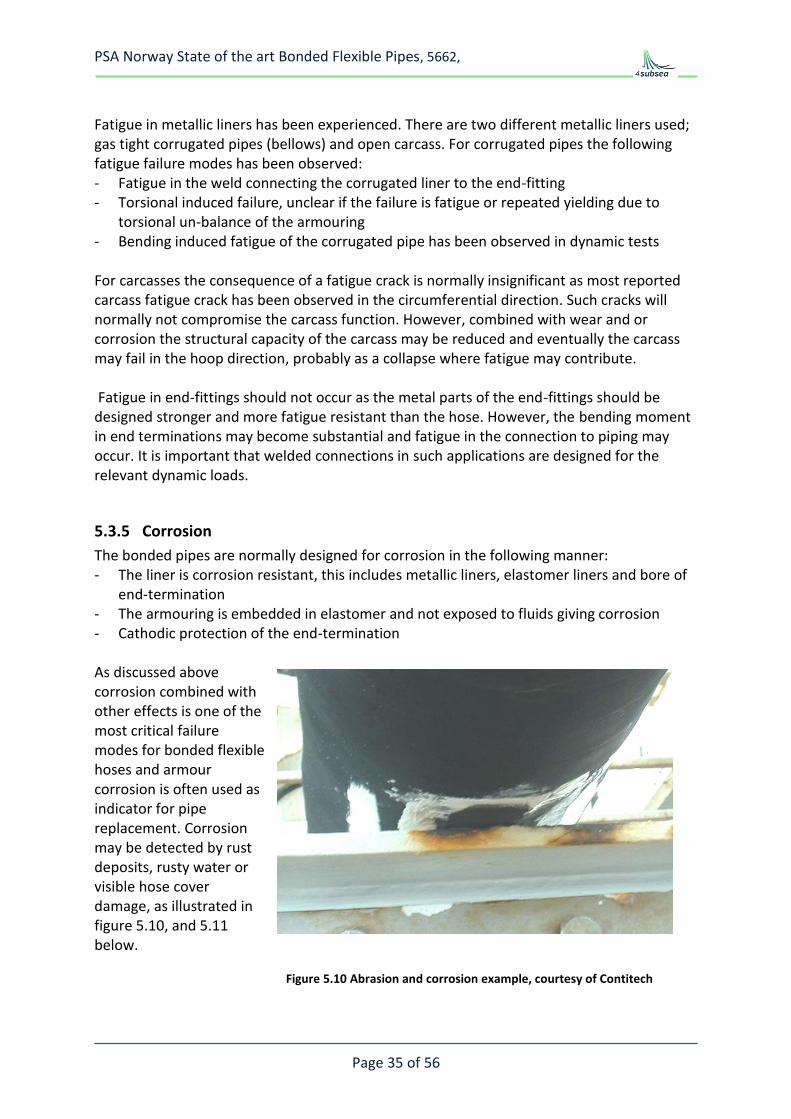
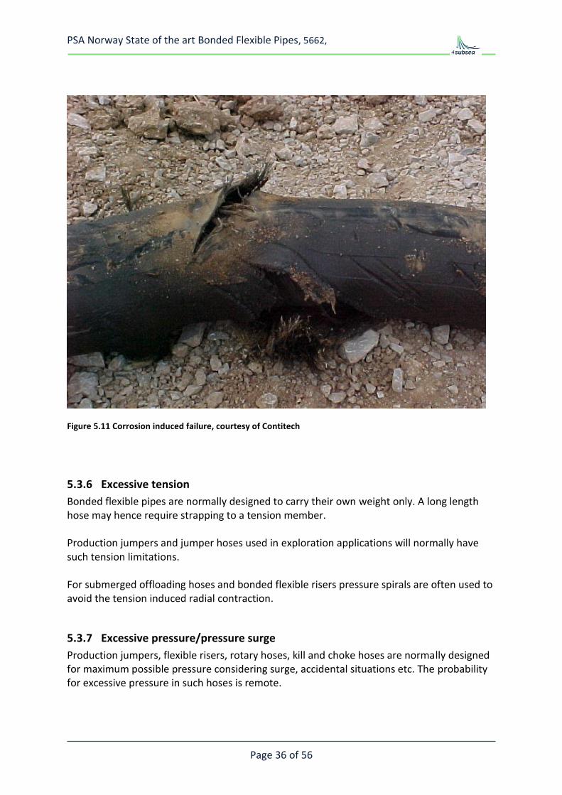
end-termination - The armouring is embedded in elastomer and not exposed to fluids giving corrosion - Cathodic protection of the end-termination As discussed above corrosion combined with other effects is one of the most critical failure modes for bonded flexible hoses and armour corrosion is often used as indicator for pipe replacement. Corrosion may be detected by rust deposits, rusty water or visible hose cover damage, as illustrated in figure 5.10, and 5.11 below.
Figure 5.10 Abrasion and corrosion example, courtesy of Contitech
PSA Norway State of the art Bonded Flexible Pipes, 5662,
Page 36 of 56
Figure 5.11 Corrosion induced failure, courtesy of Contitech
5.3.6 Excessive tension
Bonded flexible pipes are normally designed to carry their own weight only. A long length hose may hence require strapping to a tension member. Production jumpers and jumper hoses used in exploration applications will normally have such tension limitations. For submerged offloading hoses and bonded flexible risers pressure spirals are often used to avoid the tension induced radial contraction.
5.3.7 Excessive pressure/pressure surge
Production jumpers, flexible risers, rotary hoses, kill and choke hoses are normally designed for maximum possible pressure considering surge, accidental situations etc. The probability for excessive pressure in such hoses is remote.
PSA Norway State of the art Bonded Flexible Pipes, 5662,
Page 37 of 56
Offloading hoses on the other hand are normally part of a system consisting of pumps and valves which are designed to work together. Malfunction or mal-operation of the system has in several events resulted in pressure surges higher than the burst capacity of the hose. This effect caused the hose rupture on Statfjord, ref figure 5.12. In such events the weakest part of the system will fail, normally this will either be the hose or the Marine Breakaway Coupling. Marine Breakaway Couplings are designed to part at a pressure lower than the burst capacity of the hose and close the flow slowly such that the hose see no critical pressure surge. Such Marine Breakaway Couplings has prevented oil spills in many locations all around the world, however, un-intended parting has also been reported in some cases.
Figure 5.12 Ruptured offloading hose at Statfjord 2007, Ref. 12
5.3.8 Rapid gas decompression and elastomer degradation
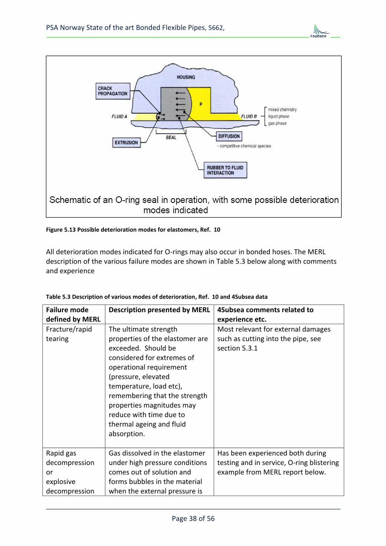
HSE research report 320, prepared by MERL, summarises the failure modes and deterioration for elastomers used for oil and gas service, Figure 5.13 illustrates important modes.
Failure
PSA Norway State of the art Bonded Flexible Pipes, 5662,
Page 38 of 56
Figure 5.13 Possible deterioration modes for elastomers, Ref. 10
All deterioration modes indicated for O-rings may also occur in bonded hoses. The MERL description of the various failure modes are shown in Table 5.3 below along with comments and experience
Table 5.3 Description of various modes of deterioration, Ref. 10 and 4Subsea data
Failure mode defined by MERL
Description presented by MERL
4Subsea comments related to experience etc.
Fracture/rapid tearing
The ultimate strength properties of the elastomer are exceeded. Should be considered for extremes of operational requirement (pressure, elevated temperature, load etc), remembering that the strength properties magnitudes may reduce with time due to thermal ageing and fluid absorption.
Most relevant for external damages such as cutting into the pipe, see section 5.3.1
Rapid gas decompression or explosive decompression
Gas dissolved in the elastomer under high pressure conditions comes out of solution and forms bubbles in the material when the external pressure is
Has been experienced both during testing and in service, O-ring blistering example from MERL report below.
PSA Norway State of the art Bonded Flexible Pipes, 5662,
Page 39 of 56
(ED)
lost. The bubbles may grow sufficiently to cause fracture of the material (e.g. seals) or of an interface (e.g. between the liner and adjacent layer in a hose).
Stress relaxation
Reduction of force over time under constant deformation conditions resulting in loss of ability to seal for un-energised seals. Contributions from both physical effects and chemical ageing effects. It is usually the latter that govern long-term performance. For seals, the effects are countered by swelling due to thermal expansion and absorption of fluids.
No known failure directly caused by this. However, geometrical changes such as elongation and twist have been reported. There are indications that such changes may reduce the pipe capacity significantly.
Creep
Increase in deformation with time under constant force/pressure conditions. Contributions from both physical effects and chemical ageing effects. It is usually the later that governs long-term performance. Associated with extrusion failures in seals.
Normally not critical for bonded flexible pipes, however, comment to stress relaxation above is relevant also here.
Swelling
Absorption of fluids over time resulting in excessive stress if constrained (e.g. seal) or excessive deformation and weakening of the elastomer if unconstrained. Enhanced by thermal expansion effects. Governed by the compatibility of the fluid with the material. A small amount can be beneficial, e.g. in low pressure gas line seals, abandonment permanent plugs.
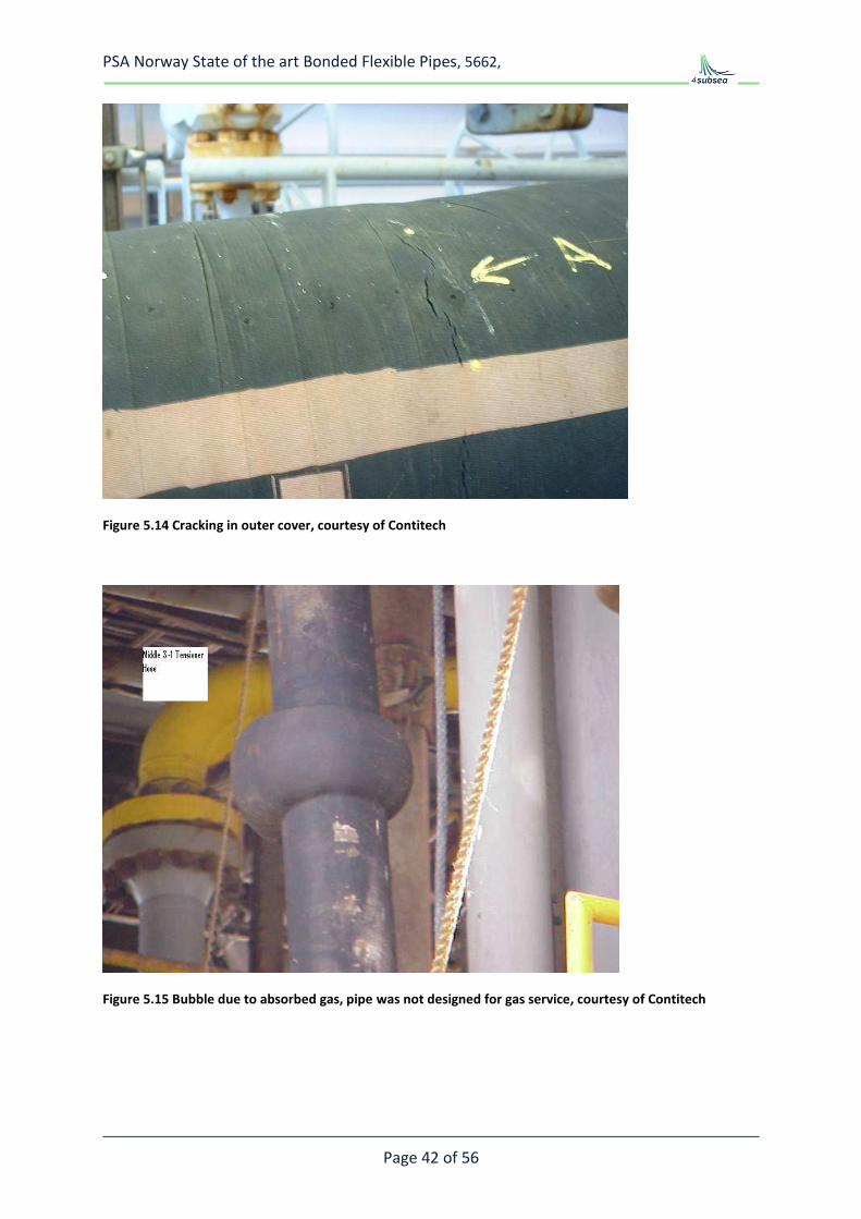
Relevant in particular for high pressure gas service where swelling and/or explosive decompression has resulted in collapse of the internal carcass. For gas service there will be gas absorption in the pipe wall. To control the cover layer bonding it is required to control the pressure in the wall by either gas draining or reduced gas permeation through liner, Figure 5.15.
Thermal contraction
Caused by reductions in temperature which may also result in hardening and increased stress relaxation; the
Cracking of bonded flexible pipes may occur at low temperatures, however as long as the pipe is used within the specified temperature range, this is
PSA Norway State of the art Bonded Flexible Pipes, 5662,
Page 40 of 56
combined effect may result in loss of sealing force in seals at low temperatures. Associated with the Tg of the elastomer.
normally not a problem. Bonded flexible hoses are frequently used for LPG loading and adequate elastomer are available for most services down to about -50 deg C
Chemical degradation (ageing)
Chemical changes due to attack either by a constituent of the contacting fluid, including environmental oxygen (aerobic ageing) or ongoing vulcanisation (anaerobic ageing). Resultant changes in mechanical properties might include stiffness changes that may affect functional performance, e.g. an increase in stiffness resulting from ageing may result in excessive fatigue forces being generated in flexible joints.
Selection of adequate elastomer for a given service is important. Example of surface fracturing of HNBR in contact with treatment chemical from MERL below.
UV and ozone cracking
Component surfaces exposed to UV and ozone prior to installation or during service must be sufficiently resistant, e.g. hose covers.
Provided manufacturer recommendations are considered and the pipe is inspected in adequate intervals this will normally not result in failure of a bonded hose
Fatigue crack growth in elastomer
Crack growth under repeated strain cycling in dynamically loaded components (flexible joints, hoses). Fatigue resistance of elastomers may be reduced by elevated temperatures, ageing and swelling by fluids.
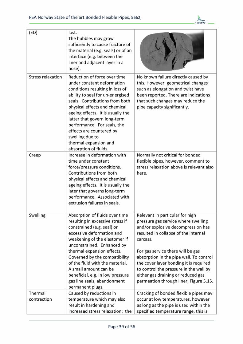
Fatigue failures in corrugated liners resulting in the elastomer being exposed to an aggressive fluid have also been reported. Cracking of then external sheet has also been experienced, see Figure 5.14
Abrasion/erosion
Loss of material over time by rubbing against another surface or fluid flow with and abrasive medium.
Material loss of the pipe cover is only critical if it leads to exposure of the armouring. This is one of the most frequent failure modes for bonded flexible pipes
Bond failure
Hose end fittings and the metal plates in flexible joints are bonded to elastomer layers. Appropriate bonding agents for the type of elastomer and metal should be used. The
The experience with these type of failure modes is addressed in Table 5.2
PSA Norway State of the art Bonded Flexible Pipes, 5662,
Page 41 of 56
bond is formed during the curing (vulcanization) process. Inadequate bond strength may be a result of inadequate manufacturing conditions or degradation caused by fluid ingress and corrosion.
Overstressing or degradation of polymer in end fitting
Several principles are used for termination of the armouring in the end-fitting.: - Hard rubber with high shear
strength and efficient load transfer from armours to end termination
- Mechanical grip on the wires either as swaging directly on the armour wires or be hoop wrapping outside the armours to force the armours to follow a profiled nipple.
- Use of epoxy - Combination If cracking in the polymer occur the hose will normally fail either by leaking or bursting. The polymers used in the end-fitting are not exposed to the same strain as the rubber in the hose, however, the mechanical load may be significant and materials with adequate long term strength has to be used.
The pipe qualification process shall in principle ensure that end termination is stronger than the hose. However, for combined loads like high tension and pressure pull-off failures for entire end-fittings has been observed. Further liner leaks due to e.g. fatigue of corrugated pipes will often propagate a crack through the end-fitting polymer.
PSA Norway State of the art Bonded Flexible Pipes, 5662,
Page 42 of 56
Figure 5.14 Cracking in outer cover, courtesy of Contitech
Figure 5.15 Bubble due to absorbed gas, pipe was not designed for gas service, courtesy of Contitech
PSA Norway State of the art Bonded Flexible Pipes, 5662,
Page 43 of 56
6 INTEGRITY MANAGMENT
6.1 General
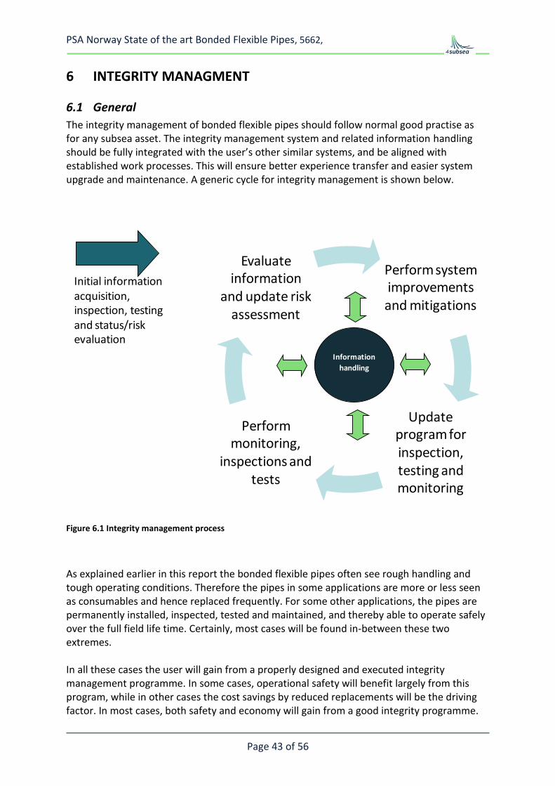
The integrity management of bonded flexible pipes should follow normal good practise as for any subsea asset. The integrity management system and related information handling should be fully integrated with the user’s other similar systems, and be aligned with established work processes. This will ensure better experience transfer and easier system upgrade and maintenance. A generic cycle for integrity management is shown below.
Perform system improvements and mitigations
Update program for inspection, testing and monitoring
Perform monitoring,
inspections and tests
Evaluate information
and update risk assessment
Information
handling
Initial information acquisition, inspection, testing and status/risk evaluation
Figure 6.1 Integrity management process
As explained earlier in this report the bonded flexible pipes often see rough handling and tough operating conditions. Therefore the pipes in some applications are more or less seen as consumables and hence replaced frequently. For some other applications, the pipes are permanently installed, inspected, tested and maintained, and thereby able to operate safely over the full field life time. Certainly, most cases will be found in-between these two extremes. In all these cases the user will gain from a properly designed and executed integrity management programme. In some cases, operational safety will benefit largely from this program, while in other cases the cost savings by reduced replacements will be the driving factor. In most cases, both safety and economy will gain from a good integrity programme.
PSA Norway State of the art Bonded Flexible Pipes, 5662,
Page 44 of 56
Inspections, testing and monitoring are all key elements for a successful integrity management program. With a good system for information handling a cost effective integrity management system may be established. Details in what to do and how to do this will be different between pipe types and recommendations may vary from the different vendors. For all applications the vendor experiences and recommendations should be implemented in the established integrity management program, see typical vendor recommendations below. Experiences gained throughout the operational life should be basis for improvements, both within the user’s organization and preferable also shared with a broader audience.
6.2 Inspection, testing and monitoring
Monitoring One of the key activities in the integrity management program for bonded flexible pipes is the monitoring of operational parameters. Typically this could be continuous time trace monitoring of pressure and temperature, frequent sampling of fluid composition, H2S, CO2, and monitoring of dynamics and environmental parameters. For bonded flexible pipes in gas applications, the pressure cycling or more precisely the large pressure relief may be vital for the performance. Good operational routines and careful monitoring of adherence to these routines could be important for successful operation of these pipes. Some bonded flexible pipes may be especially sensitive to torsion due to thin walled internal steel liners. For some special applications of these type of bonded flexible pipes, monitoring of vessel motions may be of special importance. The use of any chemicals in injection or production lines should be closely monitored and carefully checked against the relevant material compatibility charts. The monitored parameters should be reviewed regularly and seen in relation to the other inspection and testing activities. Early actions should be taken if the bonded flexible pipe is operated outside or very close to established limits. Further such data are important for extended life evaluations and possible premature failure investigations. Inspection General visual inspection is the most commonly used inspection technique for bonded flexible pipes. If this inspection reveals any irregularities a closer investigation should be performed. The close visual inspection could either be targeted at areas identified as critical during the planning phase or be a result of findings in a general visual inspection. All surface irregularities of the bonded flexible pipes and areas around the end fittings shall be carefully documented by photos and measurements. Comparisons with known failure modes and previous inspection records should form basis for further actions.
PSA Norway State of the art Bonded Flexible Pipes, 5662,
Page 45 of 56
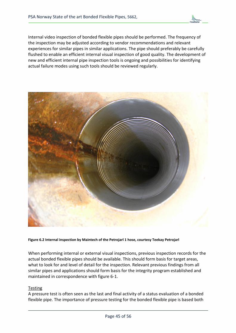
Internal video inspection of bonded flexible pipes should be performed. The frequency of the inspection may be adjusted according to vendor recommendations and relevant experiences for similar pipes in similar applications. The pipe should preferably be carefully flushed to enable an efficient internal visual inspection of good quality. The development of new and efficient internal pipe inspection tools is ongoing and possibilities for identifying actual failure modes using such tools should be reviewed regularly.
Figure 6.2 Internal inspection by Maintech of the Petrojarl 1 hose, courtesy Teekay Petrojarl
When performing internal or external visual inspections, previous inspection records for the actual bonded flexible pipes should be available. This should form basis for target areas, what to look for and level of detail for the inspection. Relevant previous findings from all similar pipes and applications should form basis for the integrity program established and maintained in correspondence with figure 6-1. Testing A pressure test is often seen as the last and final activity of a status evaluation of a bonded flexible pipe. The importance of pressure testing for the bonded flexible pipe is based both
PSA Norway State of the art Bonded Flexible Pipes, 5662,
Page 46 of 56
the design codes typically used, the difficulties in revealing internal pipe wall failures, and practical experiences. The pressure tests may typically be planned to confirm leak tightness of the pipe and related connections, or the test could be focused on confirming structural integrity of the pipe. The leak tests could be performed at operating pressure, while pressure tests will typically be performed at 1.2 to 1.5 times the design pressure.
6.3 Information handling
Efficient handling of information in a long term perspective is vital to successful integrity management of bonded flexible pipes. To achieve this within an operational organization the information handling routines, tools and databases have to be fully integrated with well established work processes. This will enable the long term continuity needed for efficient access to information, maintenance of historical data and analysis and assessments based on all monitoring, inspection, testing and possible repair data. The status reporting for the bonded flexible pipes should be integrated with the information handling. The integrity management system should be highly interactive in order to maintain a good overview of the present status, critical areas to improve, actions to follow up and experiences to shear within own organization and with the industry.
6.4 Typical storage and operation recommendations for loading hoses
All the loading hose manufacturers deliver their hoses with dedicated recommendations for their product. The below example is based on the Trelleborg Kleline catalogue and may serve as an example of how the manufacturers recommend to handle and operate the hoses. Please note that the below text is only an example; the example is not complete and should never be used for any specific hose.
Storage area The storage area must provide an efficient protection against: – excessive temperatures – ozone, keep away from any ozone source – sunlight – oils, solvents, corrosive vapours – insects and rodents Regular inspections are necessary to ensure that each crate, hose or stack is in good condition. In order to facilitate the removal operations the serial number and delivery date should be written on the wooden protective blanks; the hoses will then be sent
on site in their order of arrival sequence. Finally each hose should be carefully examined, internally and externally, and the forecaste date for putting into service registered.
It is essential to know the assembly site and its environmental characteristics (storage area distance, shore, quay, beach, tides, currents, etc.), and the equipment at the disposal of the operator; thus to optimize the place and manner of connection of floating and submarine lines.
PSA Norway State of the art Bonded Flexible Pipes, 5662,
Page 47 of 56
Assembly area The assembly area may be: a beach, a quay, a jetty, a deck. Choose a place from where it will be easy to proceed to the launching with a minimum of handling. Before using the assembly area, make sure it is free of any object likely to damage hoses. Connections According to the general arrangement drawing, the hoses will be connected together. Be careful of the identification of hoses and their possible orientation on the line; concerned hoses are: – specially end reinforced – extra reserve buoyancy – retaining collar arrangement, etc. Make sure there is no prior damage. Each hose serial number will be recorded in order to know its position in the line and to be sure to retrace it for the future operations. Immediately before the connecting operation remove the wooden flanges, clean with water each integrated gasket. Check that for no foreign body (sand, fabric, wood, ...) remains inside the hose. For submarine hose only, it is imperative at assembling operations to align the longitudinal white stripe situated on the outside cover. Use suitable studbolts, each equipped with nuts and put all the studbolts in place before beginning to tighten the flanges. The tightening will be made on diametrically opposed studbolts and checked by using a dynamometric wrench. Testing and inspection After complete assembly, the line(s) will be tested for leak detection. Pressure pump, recorder, pressure gauge, plugs, etc., are needed. The line will be filled with water and drained carefully to remove all air before
raising pressure. Fluorescent agent can be added to the water, specially when this test is made with hoses afloat in sea water.
Pressure test must be carried out at least every 6 months and will be done with the line(s) full of water, at a pressure of 15 bars and for at least 3 hours. The sea conditions must be still, with minimum swell amplitude and without current reversal so as to limit the pressure variations. The replacement of one line, a section of line or a hose pursuant to damage or a retirement will be carried out with the same care and preparation as for the original installation of the SPM.
The below onshore testing will be carried out : • at the terminal close down for maintenance operations • after a damage to the terminal • after 4 years of service Depending upon these test results a reinstallation of the hoses can be decided. Visual inspection An internal and external examination of each hose will be made to check for damage such as cuts, tears, abrasion, deformation, blister, corrosion, etc. Hydrostatic test Except for the 15 cycles in pressure, this test will be made according to the OCIMF guide and the elongation values will be recorded and compared with the previous ones and with the tests at factory when this same test was originally done. The hoses, which under this test will show a non acceptable elongation, swelling, twisting or leak traces, will be rejected. Vacuum test The inspection of the liner through translucent flanges and with adequate lighting must not show any delaminating of the liner or collapsing of the hose.
PSA Norway State of the art Bonded Flexible Pipes, 5662,
Page 48 of 56
6.5 Exploration hoses
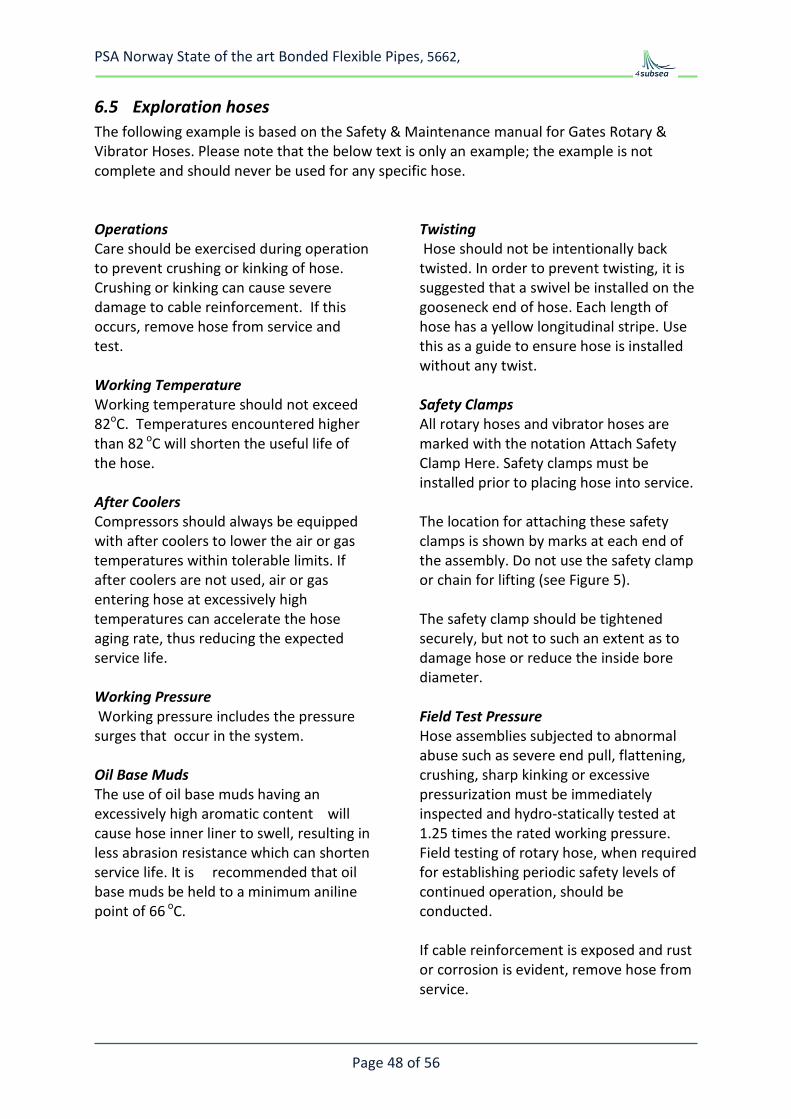
The following example is based on the Safety & Maintenance manual for Gates Rotary & Vibrator Hoses. Please note that the below text is only an example; the example is not complete and should never be used for any specific hose. Operations Care should be exercised during operation to prevent crushing or kinking of hose. Crushing or kinking can cause severe damage to cable reinforcement. If this occurs, remove hose from service and test. Working Temperature Working temperature should not exceed 82oC. Temperatures encountered higher than 82 oC will shorten the useful life of the hose. After Coolers Compressors should always be equipped with after coolers to lower the air or gas temperatures within tolerable limits. If after coolers are not used, air or gas entering hose at excessively high temperatures can accelerate the hose aging rate, thus reducing the expected service life. Working Pressure Working pressure includes the pressure surges that occur in the system. Oil Base Muds The use of oil base muds having an excessively high aromatic content will cause hose inner liner to swell, resulting in less abrasion resistance which can shorten service life. It is recommended that oil base muds be held to a minimum aniline point of 66 oC.
Twisting Hose should not be intentionally back twisted. In order to prevent twisting, it is suggested that a swivel be installed on the gooseneck end of hose. Each length of hose has a yellow longitudinal stripe. Use this as a guide to ensure hose is installed without any twist. Safety Clamps All rotary hoses and vibrator hoses are marked with the notation Attach Safety Clamp Here. Safety clamps must be installed prior to placing hose into service. The location for attaching these safety clamps is shown by marks at each end of the assembly. Do not use the safety clamp or chain for lifting (see Figure 5). The safety clamp should be tightened securely, but not to such an extent as to damage hose or reduce the inside bore diameter. Field Test Pressure Hose assemblies subjected to abnormal abuse such as severe end pull, flattening, crushing, sharp kinking or excessive pressurization must be immediately inspected and hydro-statically tested at 1.25 times the rated working pressure. Field testing of rotary hose, when required for establishing periodic safety levels of continued operation, should be conducted. If cable reinforcement is exposed and rust or corrosion is evident, remove hose from service.
PSA Norway State of the art Bonded Flexible Pipes, 5662,
Page 49 of 56
7 REPAIR Generally speaking repair of the hose should be limited to minor damage of the outer cover. All the bonded hose manufacturer specify that cover damage with exposure of the armouring should not be repaired and the hose taken out of service. All the manufacturers have repair kits for cover damage where adequate repair material, glue and repair manual are included. Internal liner repair, repair of a leaking hose, repair of hose where rust deposits from the armours have been observed or repair of deformed hoses shall not be performed.
Figure 7.1 Left picture shows repairable damage, right picture is damage beyond repair, courtesy Contitech
PSA Norway State of the art Bonded Flexible Pipes, 5662,
Page 50 of 56
8 PRACTICAL EXPERIENCE SUMMARY
8.1 General
The experience reported here is based on communication with users of bonded hoses and the manufacturers. This section is based on the information obtained during this study and may be in-complete. The following general recommendation applies:
1. Pressure testing of damaged hoses, hoses on the reel with un-known residual tension or hoses that have been kinked or crushed should not be performed as premature burst or end-fitting blow off may occur.
2. A bonded hose should only be used for the intended service 3. The manufacturer guidance on service limitation, storage, handling, inspection,
testing and maintenance should be followed 4. Premature failure of both bonded and non-bonded flexible pipes used on drag
chain and other demanding jumper applications has occurred and design of such systems should be performed in close dialogue with hose manufacturer
8.2 High pressure flexible production hoses
This sub-section is based on experience with bonded flexible jumpers used topside for hydrocarbon production and injection service. Contitech (Taurus) and Dunlop has API 17K approved designs for such service. The design limitations for these bonded flexible pipes have been:
- Temperature - Gas leading to blistering or collapse - Chemical ageing - Tension
The experience is summarised below: Temperature Temperature limitations apply to all polymer materials. However, elastomer materials which can be used for bonded flexible pipes and with adequate thermal properties for hydrocarbon production exist. Provided the bonded flexible pipes are used within the design limitation the experience with bonded flexible pipes used in service temperatures of 80oC– 100oC is good, max working temp is service dependent. The actual thermal limitations for the elastomer materials used in such bonded pipes is higher, up to 150oC for the most temperature resistant elastomers , however, such temperatures are outside the experience range for bonded hoses.
PSA Norway State of the art Bonded Flexible Pipes, 5662,
Page 51 of 56
Gas Service The elastomer materials may blister if used in gas service. Blistering is a result of gas absorption when the material is exposed to high pressure gas. With a rapid decompression the absorbed gas will expand and blistering occur. MERL, Ref. 10, has documented this effect and generally speaking elastomer materials are not used in gas service for pressures exceeding 150bar. However, in certain bonded flexible pipes a steel carcass is used inside the elastomer. The carcass is a strip wound steel structure bonded to the elastomer, the carcass is not leak proof. The elastomer is then partly shielded from gas exposure and partly prevented from swelling due to gas absorption; the rubber is enclosed by the carcass on the inside and the steel armouring on the outside. Experience has shown that bonded flexible pipes may operate at higher gas pressure than the elastomer itself. This is verified by comparing test results from elastomer O-rings with experience from bonded flexible pipes. Successful long term operation with about 300bar gas at 60 degC has been experienced. On the other hand collapse of the internal carcass or the transition to end-fitting due to swelling of the elastomer has been experience both during service and in tests. Some operators are hence not using bonded flexible pipes for high pressure gas service. There exist bonded flexible pipe designs with a gas tight liner, ref Figure 4.5 . The experience with such designs used in production service is limited offshore Norway. The only known application offshore Norway suffered from fatigue of the corrugated steel tube used as liner and the bonded hose started to leak after relative short period of operation. For such design it is hence important that the corrugated liner is not welded in location where bending may occur and further such pipes should not be twisted or exposed to high torque loads. Chemical ageing Normally the materials selected are based on exposure to the fluid transported through the bonded flexible pipe. For most of the production jumpers a carcass is used and the elastomer is hence partly shielded from the fluid. The carcass is not leak proof and locally the elastomer will be exposed. Generally speaking it seem that the material selected based on general material properties derived from testing of material samples are adequate materials for bonded flexible pipes. General ageing Reduced pressure capacity of bonded flexible pipes after some time in operation has been experienced. Neither the degradation rate nor the general ageing process is known in any detail. Tension Standard bonded hoses are designed with a limited tension capacity. The manufacturer guidance is normally to limit the tension to the weight of one hose segment. For topside
PSA Norway State of the art Bonded Flexible Pipes, 5662,
Page 52 of 56
jumpers this is normally not a governing criterion. For riser applications on the other hand, tension capacity and additional reinforcement must be considered Drag chain application The following statements with relevance for bonded hoses have been copied from “A summary Report on FPSO, Lessons Learned, gathered from 5 Norwegian FPSOs, May 2002 - 20 September 2002”, Prepared for the Norwegian Oil Industry Association, OLF, Ref. 11. Drag Chains 2 out of 5 FPSO’s have drag chains as an alternative to a swivel. Specific problems experienced include hose and electric cable failure due to wear from bending, wear pads worn out, difficulty of access, and damage caused by running into the end stops. In addition the drag chain limits the free rotation of the vessel requiring thrusters to be serviceable at all times.
8.3 Offloading hoses
General hose experience
Long service life from 10 to 20 years may be achieved for submarine application where environmental limitations and loading method are properly established.
Long service life can also be achieved for floating hoses, but the occurrence of unpredictable/accidental events (bad handling, ships crossing the line, wearing against hawser, chains and other hoses) can shorten the service life.
OCIMF hoses have been designed to withstand the pressure/tension and bending loads generated by most of the usual offloading application.
TRELLEBORG has an offloading hose design approved according to API 17K and they are able to adapt the hose design for higher pressure and tension resistance. One example is the hose provided to SHELL for the BONGA deep water field. The Oil Offloading Line is a 2200 m long and suspended in submerged lazy wave configuration. The 2200 m length is based on jointed 12m long hose sections, see Figure 4.6. This hose has been designed for a service life of 20 years and has been designed for dynamic service in 300 m water depth full of oil.
Poor handling has often resulted in hose damage such as: - damage the foam jacket for the floating hoses - damage the outer cover and create direct contact between sea water and
reinforcement components - can generate bending radius below the MBR and so create failure inside the structure
The use of a helix introduce an asymmetry in the structure and for the torsion loads in the "unscrewing" direction of the helix, the inter-ply stresses are amplified and accelerate the fatigue that can generate de-lamination. It is also to be noted that due to the presence of
PSA Norway State of the art Bonded Flexible Pipes, 5662,
Page 53 of 56
the helix, all dynamic axial loads are partially converted into torsion loads generating high inter-ply stresses.
Offloading systems are designed with a moderate pressure rating governed by the offloading pump capacity. Most offloading system are designed such that pressure surge will be controlled. The most common way of doing this is to introduce a MBC (Marine Breakaway Coupling). The MBC will part at a given pressure or tension and slowly close the hose ends thereby limiting the leak to an absolute minimum and ensuring no critical surge pressure.
For “North Sea tankers” all valves are designed for slow closure. However, mal-functional valves has resulted in excessive pressure surges and full parting of offloading hoses. It is unlikely that the hose was weaker than expected in these events.
The oil spill rate from bunkering operations is high. It is expected that many of these are related to improper hose management programs and improper procedures. The bunkering hoses are outside the scope of this report and this is hence only an observation.
Reeling of long length hoses and in particular submerged hoses may require high axial tension. Most bonded hoses have limited tension capacity and will elongate when tensioned. Reeling of an elongated hose will result in hose tension and large radial forces locked in the reeled hose. It is important that the hose and reel is designed for such tension. Premature burst failure during testing of hoses reeled with high tension has been observed. Hose operation experience The following statement with relevance for offloading hoses has been copied from “A summary Report on FPSO, Lessons Learned, gathered from 5 Norwegian FPSOs, May 2002 - 20 September 2002”, Prepared for the Norwegian Oil Industry Association, OLF, Ref. 11:
Shuttle tanker/offloading FPSO/Shuttle tanker offloading has been very successful. Only two minor incidents occurred out of approx. 1000 offloadings - one contact when some light structural damage was sustained and one rope round the thruster. Missed loadings due to weather have also been very few.
As indicated in section 2 there has been two recent failures with offloading systems offshore Norway. To 4Subsea knowledge neither of these were related to malfunction of the hose. However, both incidents seem to have been related to surge pressures exceeding the hose capacity. Proper design of the system to either avoid such surge pressure or to be strong enough to resist the surge pressure in any events should hence be performed. If the hose shall be designed for such pressures it may be required to design the hose for pressure ratings outside the OCIMF specification. An OLF, Ref. 11, workgroup prepared a note related to lessons learned from FPSOs operated offshore Norway including one part related to loading hose handling. This section is copied below, as shown it is of utmost importance to have good procedures and experience personnel for such operations. It seems that hose failures with properly operated and maintained systems are very unlikely.
PSA Norway State of the art Bonded Flexible Pipes, 5662,
PSA Norway State of the art Bonded Flexible Pipes, 5662,
Page 55 of 56
8.4 Exploration hoses, including, mud, cement, kill and choke
The general experience with bonded hoses in such applications is good. Hoses are inspected, tested and replaced from time to time. The hoses are used in an extremely demanding service and hose failures occur. The general experience may be summarised as;
- Kill and choke jumpers on drilling rigs should have relatively high bending stiffness to avoid excessive bending when the hose is in axial compression. Some operators prefer the stiffer non-bonded jumpers in such applications.
- Rotary hoses, mud hoses and cement hoses are normally bonded hoses. In these applications bonded hoses are preferred due their flexibility.
- Spill of oil based mud have been reported in a number of events offshore Norway. In addition personal injury due to hose burst has been reported by MMS.
- The actual maintenance program followed by the users of such hoses is unclear to 4Subsea
8.5 Seminars / forums / development of standards
Several organisations and forums address bonded hoses and operations involving use of such hoses. The work performed by API and OCIMF has strongly contributed to improving the quality of bonded hoses. The dialogue between the oil companies and the manufacturers during the preparation of API 17K is a good example. 4Subsea is not aware of any ongoing projects which promote communication related to bonded hose technology or revision of standards where both oil companies and the manufacturers for high pressure bonded hoses contribute. The communication today is hence mainly related to purchase or operation of bonded hoses.
PSA Norway State of the art Bonded Flexible Pipes, 5662,
Ref. 2 Frequency analysis of accidental oil releases from FPSO operations in the Gulf of Mexico, MMS 1435-01-99-CT-3092, DnV January 2001
Ref. 3 The International Tanker Owners Pollution Federation Ltd, ITOPF, Handbook 2007/2008
Ref. 4 OGP publication 316, “Input to the North Sea from the offshore oil & gas industry 1989 to 1998, report 2.82/316 feb. 2001
Ref. 5 HSE RESEARCH REPORT 047 ,Health & Safety Executive, “Analysis of accident statistics for floating mono-hull and fixed installations”, Prepared by Martin Muncer 2003.
Ref. 6 API spec 17K Specification for Bonded Flexible Pipe
Ref. 7 API spec 16C, Specification for Choke and Kill Systems
Ref. 8 API spec 7K Specification for Drilling and Well Servicing Equipment
Ref. 9 OCIMF, "Guide to purchasing, manufacturing and testing of loading and discharge hoses for offshore moorings", 4thn edition 1991
Ref. 10 “Elastomers for fluid containment in offshore oil and gas production: Guidelines and review”, MERL Ltd for the Health and Safety Executive 2005
Ref. 11 “A summary Report on FPSO, Lessons Learned, gathered from 5 Norwegian FPSOs, May 2002 - 20 September 2002”, Prepared for the Norwegian Oil Industry Association, OLF