88
PSEN sg2c Operating Manual 1003267-EN-04 } PSEN sensor technology

PSEN sg2c
Operating Manual 1003267-EN-04
} PSEN sensor technology

PrefaceThis document is a translation of the original document.
All rights to this documentation are reserved by Pilz GmbH & Co. KG. Copies may be madefor internal purposes. Suggestions and comments for improving this documentation will begratefully received.
Source code from third-party manufacturers or open source software has been used forsome components. The relevant licence information is available on the Internet on the Pilzhomepage.
Pilz®, PIT®, PMI®, PNOZ®, Primo®, PSEN®, PSS®, PVIS®, SafetyBUS p®,SafetyEYE®, SafetyNET p®, the spirit of safety® are registered and protected trademarksof Pilz GmbH & Co. KG in some countries.
SD means Secure Digital

Contents
Operating Manual PSEN sg2c1003267-EN-04
3
Section 1 Introduction 51.1 Validity of documentation 51.2 Using the documentation 51.3 Definition of symbols 5
Section 2 Overview 72.1 Scope of PSEN sg2c Unit 72.2 Unit features 7
Section 3 Safety 83.1 Intended use 83.2 Safety regulations 83.2.1 Safety assessment 83.2.2 Use of qualified personnel 83.2.3 Warranty and liability 93.2.4 Disposal 93.3 For your safety 9
Section 4 Function description 104.1 Normal /Unlock mode 104.2 Escape release 114.3 Auxiliary release 134.4 Restart interlock 144.5 Holding forces 154.6 Pushbutton 164.7 Device types 174.8 Block diagram 21
Section 5 Wiring 225.1 Notes on cable run 225.2 Recommended cable cross sections 235.3 General wiring guidelines 235.4 Terminal configuration 245.5 Wiring the connection terminals 255.6 E-STOP pushbutton connection 265.7 Enabling switch connection 265.8 EMC requirements 265.9 Connection to evaluation devices 275.9.1 Connection examples PNOZmulti 275.9.2 Connection examples PSS 275.10 Single connection 275.11 Series connection 28
Section 6 Installation 306.1 Initial installation of safety switch 316.2 Initial installation of handle unit 36

Contents
Operating Manual PSEN sg2c1003267-EN-04
4
6.3 Second installation of safety switch and handle unit / upgrade for left-hinged gates
37
6.4 Labelling the pushbuttons 376.5 Dimensions in mm 396.5.1 Drill holes 396.5.2 PSEN sg2c-3xxx 406.5.3 PSEN sg2c-5xxxxx 416.5.4 PSEN sg2c-5xxxxx-M12/5 42
Section 7 Adjustment 43
Section 8 Maintenance 44
Section 9 Operation 459.1 Status table 479.2 Toggle normal/unlock mode 489.3 Remedy 49
Section 10 Technical Details Order No. 570800-570804 51
Section 11 Technical Details Order No. 570806-570810 56
Section 12 Technical Details Order No. 570812-570816 60
Section 13 Technical Details Order No. 570818-570822 65
Section 14 Technical Details Order No. 570824-570828 69
Section 15 Technical Details Order No. 570830-570834 74
Section 16 Technical Details Order No. 570880-570884 78
Section 17 Safety characteristic data 82
Section 18 Order reference 8318.1 Unit 8318.2 Safety switch 8418.3 Handle unit with actuator 8518.4 Accessories 85
Section 19 Supplementary data 8719.1 Radio approval 8719.2 EC declaration of conformity 87

Introduction
Operating Manual PSEN sg2c1003267-EN-04
5
1 Introduction
1.1 Validity of documentationThis documentation is valid for the product PSEN sg2c. It is valid until new documentationis published.
This operating manual explains the function and operation, describes the installation andprovides guidelines on how to connect the product.
1.2 Using the documentationThis document is intended for instruction. Only install and commission the product if youhave read and understood this document. The document should be retained for future ref-erence.
1.3 Definition of symbolsInformation that is particularly important is identified as follows:
DANGER!
This warning must be heeded! It warns of a hazardous situation that posesan immediate threat of serious injury and death and indicates preventivemeasures that can be taken.
WARNING!
This warning must be heeded! It warns of a hazardous situation that couldlead to serious injury and death and indicates preventive measures that canbe taken.
CAUTION!
This refers to a hazard that can lead to a less serious or minor injury plusmaterial damage, and also provides information on preventive measuresthat can be taken.
NOTICE
This describes a situation in which the product or devices could be dam-aged and also provides information on preventive measures that can betaken. It also highlights areas within the text that are of particular import-ance.

Introduction
Operating Manual PSEN sg2c1003267-EN-04
6
INFORMATION
This gives advice on applications and provides information on special fea-tures.

Overview
Operating Manual PSEN sg2c1003267-EN-04
7
2 Overview
2.1 Scope of PSEN sg2c Unit} Safety switch
} Handle unit with actuator
} Colour covers for illuminated buttons
} Pin for escape release
2.2 Unit features} Safe guard locking (only for revolving gates and swing gates)
} Safe interlocking (position monitoring)
} Transponder technology
} 2 safety inputs for series connection of multiple safety switches
} 2 safety outputs
} Guard locking element keeps the safety gate from being opened unintentionally
} Detection of broken bolt tongue and broken guard locking element
} Handle unit with locking lever to attach padlocks as a restart interlock
} Auxiliary release for opening the safety gate, when the plant's voltage is switched off
} Escape release for fast manual release of the guard locking in emergency situationsfrom within the danger zone (revolving gates and swing gates)
} Suitable for left and right hinged safety gatesNote: The handle unit PSEN sg2c actuator is only suitable for revolving gates andswing gates.
} Plug-in spring-loaded terminals
} LED indicator for:
– Supply voltage/fault
– Gate locked
– State of the hazardous machine
– Request to stop the machine
– State of the inputs
– Bolt tongue engaged
} Depends on device type
– Various control elements, for example integral E-STOP pushbutton, section stoppushbutton, key-operated pushbutton, key switch...
– Coding:- coded- uniquely coded
See section entitled Device types

Safety
Operating Manual PSEN sg2c1003267-EN-04
8
3 Safety
3.1 Intended useThe safety gate system is used for guard locking and interlocking swing gates and revolvinggates.
It meets the requirements in accordance with:
} EN 60947-5-3
} EN ISO 14119
} EN 62061: SIL CL 3
} EN ISO 13849-1: Up to PL e (Cat. 4)
The safety level PL e (Cat. 4)/SIL CL 3 can be achieved when
} The safety outputs use 2-channel processing and
} The solenoid is operated 2-channel via safe relay outputs, suitable for PL e (Cat. 4)/SILCL 3 applications. Wiring errors should be excluded using appropriate measures. The potential solutionsare the protected cable layout or the use of pulsed semiconductor outputs.
3.2 Safety regulations
3.2.1 Safety assessmentBefore using a unit it is necessary to perform a safety assessment in accordance with theMachinery Directive.
Functional safety is guaranteed for the product as a single component. However, this doesnot guarantee the functional safety of the overall plant/machine. In order to achieve the re-quired safety level for the overall plant/machine, define the safety requirements for theplant/machine and then define how these must be implemented from a technical and organ-isational standpoint.
3.2.2 Use of qualified personnelThe products may only be assembled, installed, programmed, commissioned, operated,maintained and decommissioned by competent persons.
A competent person is someone who, because of their training, experience and current pro-fessional activity, has the specialist knowledge required to test, assess and operate thework equipment, devices, systems, plant and machinery in accordance with the generalstandards and guidelines for safety technology.
It is the company’s responsibility only to employ personnel who:
} Are familiar with the basic regulations concerning health and safety / accident preven-tion
} Have read and understood the information provided in this description under "Safety"
} And have a good knowledge of the generic and specialist standards applicable to thespecific application.

Safety
Operating Manual PSEN sg2c1003267-EN-04
9
3.2.3 Warranty and liabilityAll claims to warranty and liability will be rendered invalid if
} The product was used contrary to the purpose for which it is intended
} Damage can be attributed to not having followed the guidelines in the manual
} Operating personnel are not suitably qualified
} Any type of modification has been made (e.g. exchanging components on the PCBboards, soldering work etc.).
3.2.4 Disposal} In safety-related applications, please comply with the mission time TM in the safety-re-
lated characteristic data.
} When decommissioning, please comply with local regulations regarding the disposal ofelectronic devices (e.g. Electrical and Electronic Equipment Act).
3.3 For your safety
WARNING!Potential loss of safety function during adjustment and repair work!
When carrying out adjustment and repair work, make sure that the powersupply of the plant is switched off and protected against switching on again.
WARNING!Loss of safety function due to manipulative use of substitute actuating ele-ments!
When substitute actuating elements are used, these have to be installed asdescribed in chapter Initial installation of safety switch [ 31]. When sub-stitute actuating elements are used in a manipulative way to defeat the pro-tective device, operating the plant presents a threat to life.The operator has to consider this in the hazard analysis and he must de-termine possible countermeasures.

Function description
Operating Manual PSEN sg2c1003267-EN-04
10
4 Function descriptionThe interlocking and guard locking system prevents the safety gates to the danger zonefrom opening while the hazardous machine is switched on.
There is a high signal (safety gate closed and locked) at safety outputs X1-3 and X1-4 if thefollowing conditions are met simultaneously:
} Inputs X2-3 and X2-4 are high and
} The bolt tongue is within the response range and
} The guard locking element is engaged in the bolt tongue and
} The escape or auxiliary release pin is in the correct position.
Signal output X1-9 is high if:
} The bolt tongue is within the response rang
There is a low signal (safety gate open and hazardous machine function interlocked) atsafety outputs X1-3 and X1-4 if the following occurs:
} Inputs X2-3 or X2-4 are low or
} The guard locking element is outside the bolt tongue or
} The escape or auxiliary release has been operated or
} The guard locking element is not engaged in the bolt tongue.
If the safety outputs have been shut down by either of the inputs X2-3 or X2-4, they cannotbe switched back on until both inputs are low simultaneously.
To operate the solenoid, a high signal must be present at X1-6 (X2-6) and at X1-7 (X2-7)after the hazardous movement has been ended.
4.1 Normal /Unlock mode
Normal mode:The safety gate to the danger zone is not unlocked until the hazardous machine is stoppedand the pushbutton for access request has been operated.
} The guard locking element is disengaged from the bolt tongue as soon as there is ahigh signal at terminals X1-6 and X1-7 or X2-6 and X2-7, followed by operation of thepushbutton for access request.
Unlock mode:The safety gate to the danger zone is unlocked when the hazardous machine is stopped.This enables easier access for cleaning staff once the shift has ended, for example.
} The guard locking element is disengaged from the bolt tongue as soon as there is ahigh signal at terminals X1-6 and X1-7 or X2-6 and X2-7.

Function description
Operating Manual PSEN sg2c1003267-EN-04
11
4.2 Escape releaseThe escape release enables the guard locking to be manually released from within thedanger zone.
[1]
[2]
[3]
[4]
[1]
[2]
Mode of operationWithin the danger zone, if the escape release pin [1] is pressed in the direction of the safetygate, the cover on the escape release [2] detaches from the locked position and lifts up-wards. The swivel piece [3] folds downwards. The bolt tongue [4] behind the swivel piece isreleased. The safety gate can be opened immediately, enabling the operator to leave thedanger zone.

Function description
Operating Manual PSEN sg2c1003267-EN-04
12
WARNING!Loss of safety function due to the incorrect installation of the escape re-lease!
If the escape release pin is accessible from the outside, the guard lockingdevice can be released from the outside and the safety gates opened, al-though the hazardous machine is switched on. Depending on the application, serious injury or death may result.
The escape release should be installed so that it is only accessible from in-side the danger zone. It is also important to refer to the maintenance instructions (see chapter en-titled Maintenance [ 44])
INFORMATION
When the escape or auxiliary release is operated, there is a low signal atthe safety outputs X1-3 and X1-4. An error code is issued (see section en-titled Remedy [ 49]). The PSENsgate is not ready for operation againuntil the escape release or auxiliary release has been reset to its unoper-ated state and the error has been rectified and reset.Please note that the cover of the escape release has to be checked and re-installed after operation.

Function description
Operating Manual PSEN sg2c1003267-EN-04
13
4.3 Auxiliary releaseWhen the plant is powered down, the auxiliary release enables the guard locking device tobe released from the access side to the danger zone.
[1]
[2]
[4]
[3]
Mode of operation:Carefully remove the cover of the escape release (1) from the latch below. Use a screw-driver (2) to pull out the escape or auxiliary release pin (3) from the swivel piece (4). Theswivel piece folds downwards, the bolt tongue behind the swivel piece is released. Thesafety gate to the danger zone can be opened.
INFORMATION
When the escape or auxiliary release is operated, there is a low signal atthe safety outputs X1-3 and X1-4. An error code is issued (see section en-titled Remedy [ 49]). The PSENsgate is not ready for operation againuntil the escape release or auxiliary release has been reset to its unoper-ated state and the error has been rectified and reset.Please note that the cover of the escape release has to be checked and re-installed after operation.
Function description
Operating Manual PSEN sg2c1003267-EN-04
14
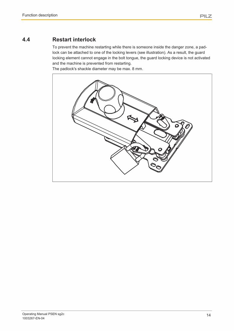
4.4 Restart interlockTo prevent the machine restarting while there is someone inside the danger zone, a pad-lock can be attached to one of the locking levers (see illustration). As a result, the guardlocking element cannot engage in the bolt tongue, the guard locking device is not activatedand the machine is prevented from restarting. The padlock's shackle diameter may be max. 8 mm.
Function description
Operating Manual PSEN sg2c1003267-EN-04
15
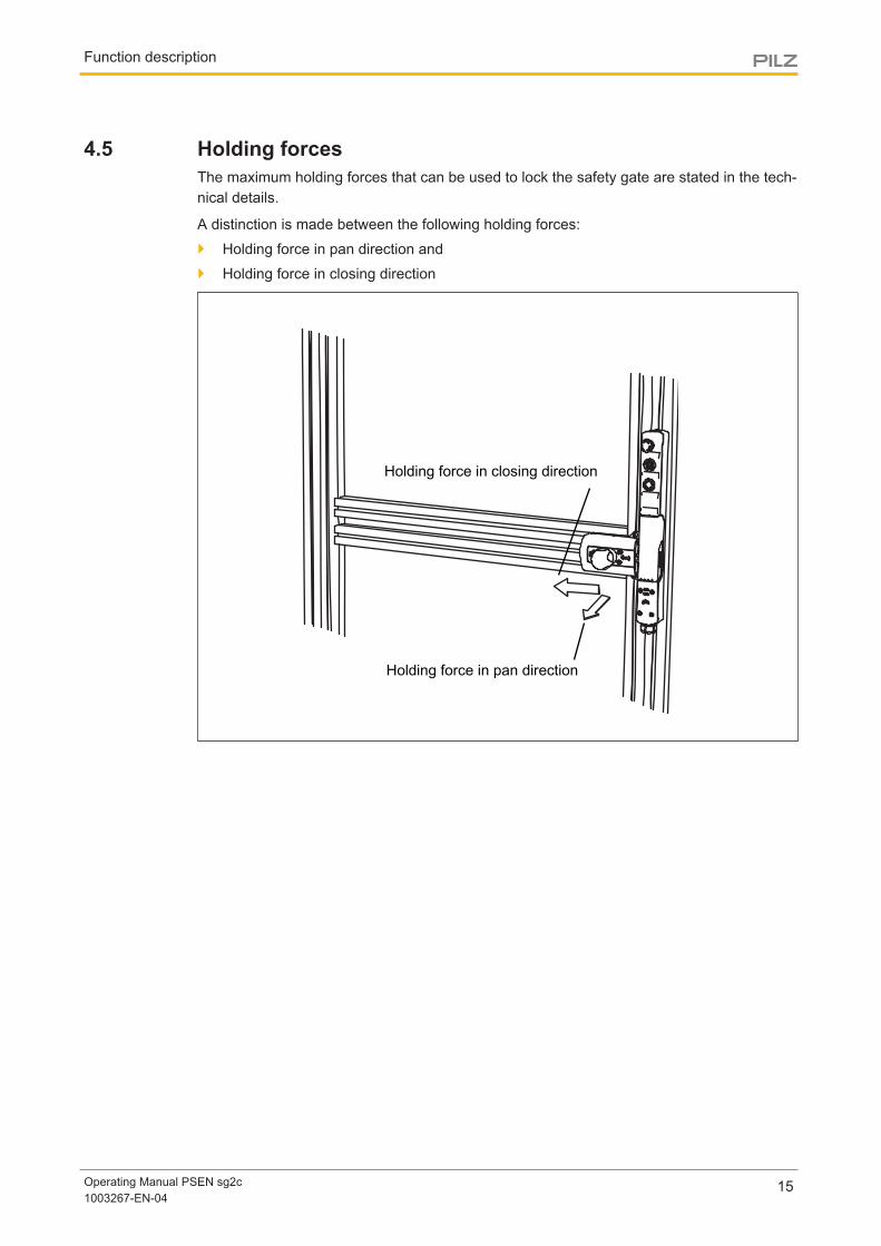
4.5 Holding forcesThe maximum holding forces that can be used to lock the safety gate are stated in the tech-nical details.
A distinction is made between the following holding forces:
} Holding force in pan direction and
} Holding force in closing direction
Holding force in closing direction
Holding force in pan direction

Function description
Operating Manual PSEN sg2c1003267-EN-04
16
4.6 Pushbutton
Pushbutton 1
Pushbutton 2
Pushbutton 1
Pushbutton 2
Pushbutton 3
Pushbutton 4
PSEN sg2c-3... PSEN sg2c-5...
E-Stop/Section stop
E-Stop/Section stop
} Pushbutton 1: pushbutton for activating the safety gate guard locking deviceBy pressing the pushbutton for activating guard locking, the guard locking element isengaged in the bolt tongue when the bolt tongue is detected by the sensor and a highsignal is present at X1-6 and X1-7 or at X2-6 and X2-7 (solenoid operation).
} Pushbutton 2: pushbutton for access request and release of the safety gate
– Pressing the pushbutton for access request disengages the guard locking elementfrom the bolt tongue when a high signal is present at X1-6 and X1-7 or at X2-6 andX2-7 (solenoid operation).
– Pressing the pushbutton for access request switches output X1-5 (access request)when a low signal is present at X1-6 and X1-7 or at X2-6 and X2-7 (solenoid opera-tion).
Depending on the design, the device also has:
} E-STOP / or section stop pushbutton} Pushbutton 3 and pushbutton 4
Pushbuttons that can be used depending on the application:
– Operating a pushbutton switches the pushbutton output
– The LEDs of the pushbuttons can be operated via the LED inputs.
Further information on the different types can be found in the section entitled Devicetypes [ 17].

Function description
Operating Manual PSEN sg2c1003267-EN-04
17
4.7 Device types21 different versions are available. They differ as follows:
} Number and quality of the pushbuttons
} Coded or uniquely coded
} With or without M12 connection for enabling switch
PSEN sg2c-3xxx PSEN sg2c-5xxxxx PSEN sg2c-5xxxxx-M12/5
[1]
[2]
[3]
[1]
[2]
[3]
[4]
[5]
[1]
[2]
[3]
[4]
[5]
[6]

Function description
Operating Manual PSEN sg2c1003267-EN-04
18
PSEN sg2c-3xxx (3 pushbuttons)[1] Pushbutton 1: pushbutton for activating the safety gate guard locking device
[2] Pushbutton 2: pushbutton for access request and release of the safety gate
[3] E-STOP / or section stop pushbutton
Type code:
PSEN sg2c - 3 L X X 2.2*3 pushbuttons = 3
Pushbutton illuminated = LPushbutton unilluminated = P
Key switch = B
E-STOP pushbutton = ESection stop pushbutton = S
No pushbutton = C
uniquely coded
[1] [2] [3]
*not included with all versions
Types:
Pushbutton 1 Pushbutton 2 E-Stop/Section stop
Coding
-3LPE Pushbuttonilluminated
Pushbuttonunilluminated
E-Stop coded
-3LBE Pushbuttonilluminated
Keyswitch
E-Stop coded
-3LPS Pushbuttonilluminated
Pushbuttonunilluminated
Sectionstop
coded
-3LBS Pushbuttonilluminated
Key-operatedpushbutton
Sectionstop
coded
-3LPC Pushbuttonilluminated
Pushbuttonunilluminated
--- coded
-3LBC Pushbuttonilluminated
Key-operatedpushbutton
--- coded
-3LPE 2.2 Pushbuttonilluminated
Pushbuttonunilluminated
E-Stop uniquely coded
Function description
Operating Manual PSEN sg2c1003267-EN-04
19
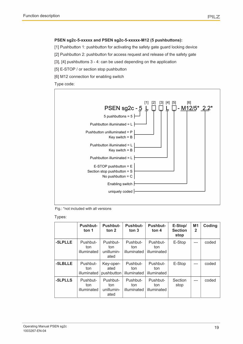
PSEN sg2c-5-xxxxx and PSEN sg2c-5-xxxxx-M12 (5 pushbuttons):[1] Pushbutton 1: pushbutton for activating the safety gate guard locking device
[2] Pushbutton 2: pushbutton for access request and release of the safety gate
[3], [4] pushbuttons 3 - 4: can be used depending on the application
[5] E-STOP / or section stop pushbutton
[6] M12 connection for enabling switch
Type code:
PSEN sg2c - 5 L X X L X - M12/5* 2.2*5 pushbuttons = 5
Enabling switch
Pushbutton illuminated = L
Pushbutton unilluminated = PKey switch = B
E-STOP pushbutton = ESection stop pushbutton = S
No pushbutton = C
uniquely coded
Pushbutton illuminated = LKey switch = B
Pushbutton illuminated = L
[1] [2] [3] [4] [5] [6]
Fig.: *not included with all versions
Types:
Pushbut-ton 1
Pushbut-ton 2
Pushbut-ton 3
Pushbut-ton 4
E-Stop/Section
stop
M12
Coding
-5LPLLE Pushbut-ton
illuminated
Pushbut-ton
unillumin-ated
Pushbut-ton
illuminated
Pushbut-ton
illuminated
E-Stop --- coded
-5LBLLE Pushbut-ton
illuminated
Key-oper-ated
pushbutton
Pushbut-ton
illuminated
Pushbut-ton
illuminated
E-Stop --- coded
-5LPLLS Pushbut-ton
illuminated
Pushbut-ton
unillumin-ated
Pushbut-ton
illuminated
Pushbut-ton
illuminated
Sectionstop
--- coded

Function description
Operating Manual PSEN sg2c1003267-EN-04
20
-5LBLLS Pushbut-ton
illuminated
Key-oper-ated
pushbutton
Pushbut-ton
illuminated
Pushbut-ton
illuminated
Sectionstop
--- coded
-5LPLLC Pushbut-ton
illuminated
Pushbut-ton
unillumin-ated
Pushbut-ton
illuminated
Pushbut-ton
illuminated
--- --- coded
-5LBLLC Pushbut-ton
illuminated
Key-oper-ated
pushbutton
Pushbut-ton
illuminated
Pushbut-ton
illuminated
--- --- coded
-5LPKLE-M12/5
Pushbut-ton
illuminated
Pushbut-ton
unillumin-ated
Keyswitch
Pushbut-ton
illuminated
E-Stop Yes coded
-5LBKLE-M12/5
Pushbut-ton
illuminated
Key-oper-ated
pushbutton
Keyswitch
Pushbut-ton
illuminated
E-Stop Yes coded
-5LPKLS-M12/5
Pushbut-ton
illuminated
Pushbut-ton
unillumin-ated
Keyswitch
Pushbut-ton
illuminated
Sectionstop
Yes coded
-5LBKLS-M12/5
Pushbut-ton
illuminated
Key-oper-ated
pushbutton
Keyswitch
Pushbut-ton
illuminated
Sectionstop
Yes coded
-5LPKLC-M12/5
Pushbut-ton
illuminated
Pushbut-ton
unillumin-ated
Keyswitch
Pushbut-ton
illuminated
--- --- coded
-5LBKLC-M12/5
Pushbut-ton
illuminated
Key-oper-ated
pushbutton
Keyswitch
Pushbut-ton
illuminated
--- Yes coded
-5LPLLE2.2
Pushbut-ton
illuminated
Pushbut-ton
unillumin-ated
Pushbut-ton
illuminated
Pushbut-ton
illuminated
E-Stop --- uniquelycoded
-5LPKLE-M12/5 2.2
Pushbut-ton
illuminated
Pushbut-ton
unillumin-ated
Keyswitch
Pushbut-ton
illuminated
E-Stop Yes uniquelycoded

Function description
Operating Manual PSEN sg2c1003267-EN-04
21
4.8 Block diagram
6
324 V
Escape
Release Pin
24 V
(Connector)
Fig.: The connections shown in blue are available depending on the device type (see section entitled Devicetypes [ 17]).

Wiring
Operating Manual PSEN sg2c1003267-EN-04
22
5 Wiring
5.1 Notes on cable runThe maximum cable run depends on the voltage drop in the supply voltage conductors forsolenoid operation. The level of voltage drop is determined by the
} cable resistance of the cables
} solenoid current of the solenoid
If the voltage drop in the supply voltage conductors becomes too high, the voltage forsolenoid operation can permanently be set to the upper tolerance range (see Technical de-tails).
The max. cable diameter is 10 mm.
Example:
} Connecting 3 safety switches in series
} Total cable run: 25 m
} Conductor cross section: 0.5 mm2
} Solenoid current per solenoid: 1.5 A
} Voltage for solenoid operation: 24 V
4
U~0.05*10*1.5*4.5~3.4 V U~0.05*5*1.5*3~1.1 V U~0.05*10*1.5*1.5~1.5 V
U~cable specific impedence*cable length*cable factor*current
Cable impedence(2x0.25 mm²)
=0.05 Ohm/meter
25 m
0
The voltage drop over all the safety switches is 6 V. This means, there are only 18.0 V atthe terminals of the last solenoid. The solenoid is no longer operated reliably. If the voltagefor operating the solenoid is increased by the max. permitted tolerance to 26.4, there arestill 20.4 V at the terminals of the last solenoid. The solenoid switches reliably.

Wiring
Operating Manual PSEN sg2c1003267-EN-04
23
5.2 Recommended cable cross sectionsThe values in the table are valid for a series connection with max. 3 sensors and a voltagefor solenoid operation of 24 V. The solenoid current is 1.5 A per solenoid.
For differing values the conductor cross section must be calculated.
Total cable run [m]1 safety switches 2 safety switches 3 safety switches
5 0.25 mm2, AWG24 0.25 mm2, AWG24 0.5 mm2, AWG21
10 0.25 mm2, AWG24 0.25 mm2, AWG24 0.5 mm2, AWG21
15 0.25 mm2, AWG24 0.25 mm2, AWG24 0.5 mm2, AWG21
20 0.25 mm2, AWG24 0.5 mm2, AWG21 x
25 0.25 mm2, AWG24 0.5 mm2, AWG21 x
30 0.25 mm2, AWG24 x x
40 0.5 mm2, AWG21 x x
50 0.5 mm2, AWG21 x x
60 0.5 mm2, AWG21 x x
70 x x x
Cable runs marked with an x are not recommended.
For operating several safety switches with greater cable runs, the cables for solenoid oper-ation (terminals X1-6 and X1-7) have to be carried individually, or several cables have to beused. If more than three safety switches are connected in series or cable runs over 60 mare required, please contact Pilz.
The permitted conductor cross section is at least 0.25 mm². To have a higher conductorcross section, two cable cores can be inserted into a terminal. This adds together the con-ductor cross sections and halves the cable resistances. In this case, use a terminal lug! Thesignals important for cable resistance are:
} 24 V (X1-1 or X2-1)
} 0 V (X1-2 or X2-2)
} the two solenoid operation signals (X1-6 and X1-7 or X2-6 and X2-7).
5.3 General wiring guidelinesPlease note:
} All metallic surfaces on the safety switch are connected to 0 V via a resistor (100kOhm) for functional earthing.
} UL requirements:
– Use copper wiring with a temperature stability of 75 °C.
– Use an LVLC supply (LVLC: limited voltage, limited current).
– Use multicore cable with a cable diameter of 6 ... 10 mm.
} When 2 cables are used, make sure that both cables have the same cable diameter,otherwise the strain relief will fail.

Wiring
Operating Manual PSEN sg2c1003267-EN-04
24
} The permitted conductor cross section for the connectors is 0.25 - 1.0 mm², 23 - 17AWG.
} When calculating the max. cable run, remember to take into account the chapter "Noteson cable run".
5.4 Terminal configuration
1
X2
3 5 7 9 11 13 15
2 4 6 8 10 12 14 16
1
X1
3 5 7 9 11 13 15
2 4 6 8 10 12 14 16
Terminal PSEN sg2c-3xxx PSEN sg2c-5xxxxPSEN sg2c-5xxxx-M12/5
X1-1 - X2-1 linked internally
+24 VDC supply voltage +24 VDC supply voltage +24 VDC supply voltage
X1-2 - X2-2 linked internally
0 V 0 V 0 V
X1-3 Safety output channel 1(OSSD1)
Safety output channel 1(OSSD1)
Safety output channel 1(OSSD1)
X1-4 Safety output channel 2(OSSD2)
Safety output channel 2(OSSD2)
Safety output channel 2(OSSD2)
X1-5 - X2-5 linked internally
Output pushbutton for ac-cess request [2]
Output pushbutton for ac-cess request [2]
Output pushbutton for ac-cess request [2]
X1-6 - X2-6 linked internally
Solenoid operation (24 V) Solenoid operation (24 V) Solenoid operation (24 V)
X1-7 - X2-7 linked internally
Solenoid operation (24 V) Solenoid operation (24 V) Solenoid operation (24 V)
X1-8 - X2-8 linked internally
Input for activating thesafety gate guard lockingdevice
Input for activating thesafety gate guard lockingdevice
Input for activating thesafety gate guard lockingdevice
X1-9 Signal output for state ofthe bolt tongue
Signal output for state ofthe bolt tongue
Signal output for state ofthe bolt tongue
X1-10 E-STOP 1.1 E-STOP 1.1 E-STOP 1.1
X1-11 E-STOP 1.2 E-STOP 1.2 E-STOP 1.2
X1-12 E-STOP 2.1 E-STOP 2.1 E-STOP 2.1
X1-13 E-STOP 2.2 E-STOP 2.2 E-STOP 2.2
Wiring
Operating Manual PSEN sg2c1003267-EN-04
25
Terminal PSEN sg2c-3xxx PSEN sg2c-5xxxxPSEN sg2c-5xxxx-M12/5
X1-14 n.c Pushbutton 3 LED3 n.c
X1-15 n.c Pushbutton 4 LED4 Pushbutton 4 LED4
X1-16 Signal output, E-STOP Signal output, E-STOP Enabling switch Pin5 andsignal output E-STOP
X2-3 Input, channel 1 Input, channel 1 Input, channel 1
X2-4 Input, channel 2 Input, channel 2 Input, channel 2
X2-9 n.c n.c Enabling switch M12 Pin1 (optional)
X2-10 n.c n.c Enabling switch M12 Pin2 (optional)
X2-11 n.c n.c Enabling switch M12 Pin3 (optional)
X2-12 n.c n.c Enabling switch M12 Pin4 (optional)
X2-13 n.c Pushbutton 3 channel 1 Pushbutton 3: Key switchrotated 90° to the left
X2-14 n.c n.c Pushbutton 3: Key switchrotated 90° to the right
X2-15 n.c Pushbutton 4 channel 1 Pushbutton 4 channel 1
X2-16 n.c n.c n.c
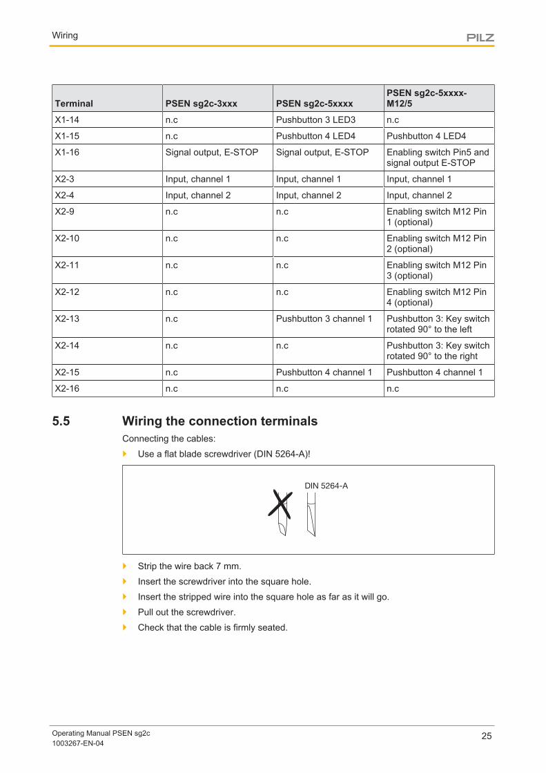
5.5 Wiring the connection terminalsConnecting the cables:
} Use a flat blade screwdriver (DIN 5264-A)!
DIN 5264-A
} Strip the wire back 7 mm.
} Insert the screwdriver into the square hole.
} Insert the stripped wire into the square hole as far as it will go.
} Pull out the screwdriver.
} Check that the cable is firmly seated.

Wiring
Operating Manual PSEN sg2c1003267-EN-04
26
5.6 E-STOP pushbutton connection
CAUTION!
With versions with integral E-STOP pushbutton, the E-STOP pushbutton(terminals X1-10 to X1-13) must be integrated into the plant/machine's E-STOP concept in accordance with EN/IEC 60204.
5.7 Enabling switch connectionDetails of the pin assignment of the female 5-pin M12 connector for the enabling switch canbe found in the block diagram and the terminal configuration.
We recommend you use the PIT en1.0p-5m-s (order no. 401 110) as the enabling switch.
5.8 EMC requirementsPlease note:
} The power supply must meet the regulations for extra low voltages with protective sep-aration (SELV, PELV).
} The inputs and outputs of the safety switch must have a protective separation tovoltages over 60 V AC.
} The supply voltage has to be at the safety switch terminals within the indicated toler-ances (see Technical details).
} the supply voltage of the safety switch must be secured with a fuse of type quickbetween 2 A and 10 A.
} The electrical installation must be performed in accordance with IEC/EN 60204.
} The assured release distance (SaO) can be influenced by external influences (e.g.: tem-perature, dirt, EMC) (see Technical details).
INFORMATION
Safety relays with a wide-range power supply or in AC device versions haveinternal potential isolation and are not suitable as evaluation devices. Onlysafety relays with a 24 VDC supply voltage are suitable.

Wiring
Operating Manual PSEN sg2c1003267-EN-04
27
5.9 Connection to evaluation devices
5.9.1 Connection examples PNOZmultiup to PL d/SIL CL 2 PL e/SIL CL 3
24 V)
FS O1
24 V)
FS O1
FS O2
5.9.2 Connection examples PSSup to PL d/SIL CL 2 PL e/SIL CL 3
24 V)
FS DO O1
24V)
FS DO O1
FS DO O2
5.10 Single connection
INFORMATION
When the solenoid is operated in single-channel, only a safety level of PL d(Cat. 2)/SIL CL 2 can be achieved.To achieve PL e (Cat. 4/SIL CL 3, the solenoid must have dual-channel op-eration, e. g. via safe pulsed semiconductor outputs with high current loadcapacity (0.9 A for 50 ms).

Wiring
Operating Manual PSEN sg2c1003267-EN-04
28
X2-4
24 V 0 V
I1 (ST) I3 (FS)
A1
A2
PSENsgate
O1 (FS)
Auswertegerät/Evaluation device/Appareil de surveillance/Dispositivo di controllo
FS: Fail-safe
ST: Standard
I4 (FS)
X2-3
X1-3 X1-4
X1-1
X1-2
X1-6 X1-5
I2 (ST)
X1-9
O3 (ST)
X1-8
O2 (FS)
X1-7
5.11 Series connection
CAUTION!Extension of delay-on de-energisation
When several (n) devices are connected in series, the delay-on de-ener-gisation time adds with the number of interconnected safety switches. The may. delay-on de-energisation is composed ofmax. delay-on de-energisation actuator + (n-1) x max. delay-on de-energisation of the inputs + delay-on de-energisation of the evaluation device
INFORMATION
When the solenoid is operated in single-channel, only a safety level of PL d(Cat. 2) / SIL CL 2 can be achieved.To achieve PL e (Cat. 4)/SIL CL 3, the solenoid must have dual-channel op-eration.
For applications with single-channel operation of the solenoid (up to PL d/SIL CL 2) a mo-mentarily overloadable safe output (1.8 A for 50 ms) can be used.

Wiring
Operating Manual PSEN sg2c1003267-EN-04
29
The device can be switched in series with all safety switches from Pilz. In the connectionexample, the safety switch guard locking device is activated / deactivated via access re-quest (X1-5). The maximum switching current of the solenoid is present only while switch-ing the solenoids for about 50 ms. The solenoids of the safety switches are switched with alow time offset of ca. 1 s, to avoid power surges at the evaluation device.
X2-3
24 V
A1
A2
PLC
PSENsgate
I1 (FS) I2 (FS)
FS: Fail-safe
ST: Standard
PSENsgate
PSENsgate
Auswertegerät/Evaluation device/Appareil de surveillance/Dispositivo di controllo
I1 (ST)
X2-3 X2-4
X1-3 X1-4
X1-9
X2-3 X2-4
X1-1
X1-1
X1-2
X1-2
X2-1X2-2
X1-6
X2-6
X1-6
X2-6
X1-7
I2 (ST)X1-9
I3 (ST)X1-9
X1-2
X2-2X2-7
I4 (ST)X1-5
X2-7
X1-7
X1-7 X1-1
X2-1
X1-3 X1-4
X2-4
X1-3 X1-4
X2-5
X1-5
X2-5
X1-5
0 V
O1 (FS)X1-6
O2 (FS)
X2-8
X1-8
X2-8
X1-8
O3 (ST)
X1-8

Installation
Operating Manual PSEN sg2c1003267-EN-04
30
6 Installation} When installing make sure you comply with the requirements of EN ISO 14119.
} The safety switch and handle unit with actuator should be installed opposite each otherin parallel.
} The safety switch and handle unit with actuator should be secured only with sockethead cap screws M5 - DIN EN ISO 4762.
NOTICE
It must not be possible to operate or remove the handle unit from inside thedanger zone. Protect the handle unit from access, e.g. by covers on thehazard side of the door.
INFORMATION
The handle unit should be protected from unauthorised removal and fromcontamination.
CAUTION!
Safety switch and handle unit
– Should not be exposed to heavy shock or vibration
– Should not be used as a limit stop

Installation
Operating Manual PSEN sg2c1003267-EN-04
31
6.1 Initial installation of safety switch} Open the cover for the escape release in the direction of opening and remove it.
} Prepare 9 mm hole for the escape release and attach profile nuts to the aluminium pro-file (see also Dimensions for the drill holes [ 39]). The escape release does not require a drill hole.

Installation
Operating Manual PSEN sg2c1003267-EN-04
32
} Align actuator guide plate and safety switch. Please note the distance between thehandle unit and the safety switch (see chapter entitled Adjustment [ 43]).
} Fix actuator guide plate and safety switch with M5 - DIN EN ISO 4762 - socket headcap screws (hexagon socket, e.g.: Bossard: BN3 (without shaft), galvanised blue,torque setting Ma = 5 Nm). Use washer M5 - DIN125A (e.g.: Bossard: BN 715, galvan-ised blue, dimension: 10 x 5.3 x 1) for this. The fixing screws on the safety switch are located under the cover of the escape re-lease. Use an appropriate screw adhesive (e.g. Loctite 2700) to protect the socket headcap screws from working loose.
WARNING!Risk of manipulation of the safety device if the actuator guide plate is notsecured permanently!
If the actuator guide plate is not secured permanently, there is a risk that thesafety function will be defeated through manipulation. Depending on the ap-plication, serious injury or death may result.
– If the actuator guide plate is installed using only the unprotectedscrews [1] accessible from the side, then one-way screws must beused for manipulation protection.
– If the screws used under the bolt tongue [2] are protected againstmanipulation, then this is not necessary.
[1]
[2]
Installation
Operating Manual PSEN sg2c1003267-EN-04
33
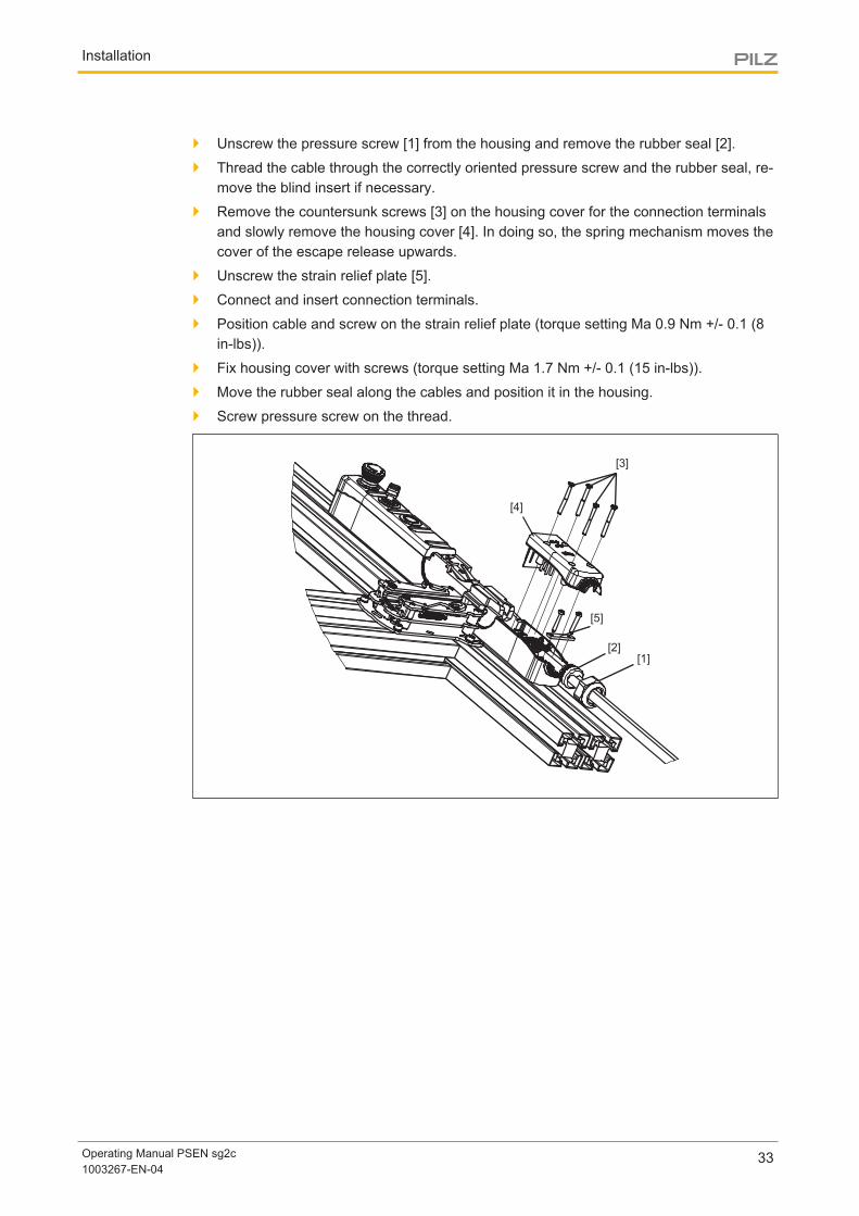
} Unscrew the pressure screw [1] from the housing and remove the rubber seal [2].
} Thread the cable through the correctly oriented pressure screw and the rubber seal, re-move the blind insert if necessary.
} Remove the countersunk screws [3] on the housing cover for the connection terminalsand slowly remove the housing cover [4]. In doing so, the spring mechanism moves thecover of the escape release upwards.
} Unscrew the strain relief plate [5].
} Connect and insert connection terminals.
} Position cable and screw on the strain relief plate (torque setting Ma 0.9 Nm +/- 0.1 (8in-lbs)).
} Fix housing cover with screws (torque setting Ma 1.7 Nm +/- 0.1 (15 in-lbs)).
} Move the rubber seal along the cables and position it in the housing.
} Screw pressure screw on the thread.
[1][2]
[3]
[4]
[5]

Installation
Operating Manual PSEN sg2c1003267-EN-04
34
} Insert the escape or auxiliary release pin [1] into the safety switch and push it right tothe back. The swivel piece [2] must be maintained in a vertical position, safe from theescape or auxiliary release pin. Screw the ball head on to the escape release pin.Check the escape release for ease of movement. Fold down the cover on the escaperelease ② and lock into position.
} Screw the ball handle [4] into the handle unit, lock the bolt tongue of the handle unit [5]into position in the actuator guide plate. (See section entitled Initial installation of handleunit [ 36]
INFORMATION
If the escape or auxiliary release pin is not inserted into the swivel piececorrectly, commissioning of the PSENsgate will be aborted and an errorcode will be issued.
[2]
[3]
[4][5]
[1]

Installation
Operating Manual PSEN sg2c1003267-EN-04
35
WARNING!Loss of safety function due to the incorrect installation of the escape re-lease!
If the escape release pin is accessible from the outside, the guard lockingdevice can be released from the outside and the safety gates opened, al-though the hazardous machine is switched on. Depending on the application, serious injury or death may result.
The escape release should be installed so that it is only accessible from in-side the danger zone. It is also important to refer to the maintenance instructions (see chapter en-titled Maintenance [ 44])
Shorten the escape release pinThe escape release pin can be shortened, if required, so that it does not extend too muchinto the danger zone.
NOTICE
Inside the danger zone, the escape release pin must protrude at least 65mm from the profile. After installation, the escape release must be checkedfor proper operation. When shortening the escape release pin, the materialof the escape release must not exceed a temperature of 100 °C
65 mm 45 mm
Pin for escape releasewith ball handle
Pin for auxiliary release
If the escape release is not to be used, the escape release pin can be shortened to a lengthof 45 mm and then be used for the auxiliary release. The auxiliary release pin is also avail-able as an accessory (see order references for Accessories [ 85]).
NOTICE
Please note that the escape release pin must not be shorter than 45 mm, toguarantee the full holding force.

Installation
Operating Manual PSEN sg2c1003267-EN-04
36
6.2 Initial installation of handle unit} Check whether the present bolt tongue is correctly oriented at the handle unit. Standard
is right-hand door hinge at delivery (leave of the door opens to the right).
} Coat the thread of the ball handle with screw adhesive (e.g. Loctite 2700) and screwfirmly together with the handle unit by hand.
Install bolt tongue with handle unit:} Remove the screw blocking the spring-loaded limit stop mechanism (see illustration
"Handle unit and actuator with screw").
} Position the screwdrivers in the slots provided on the limit stop mechanism (see illustra-tion "Unlock bolt").
} Press screwdriver towards the base plate to release the spring-loaded limit stop mech-anism.
} Engage bolt tongue with handle unit in the actuator guide.
} Ensure by moving backwards and forwards towards the limit stop that the handle unitcannot be removed from the actuator guide.
} Re-attach the screw with a torque setting of 2 Nm +/-0.1. Use an appropriate screw ad-hesive (e.g. Loctite 2700) to protect the screw from working loose.
Fig.: Handle unit and actuator with screw

Installation
Operating Manual PSEN sg2c1003267-EN-04
37
Fig.: Unlock bolt
6.3 Second installation of safety switch and handle unit /upgrade for left-hinged gates} Remove the screw blocking the spring-loaded limit stop mechanism (see illustration in
previous section "Handle unit and actuator with screw").
} Uninstall the safety switch from the installation site (compare steps in section en-titledInitial installation of safety switch [ 31] in reverse order).
} Uninstall handle unit from the gate. To do this, position the screwdrivers in the slotsprovided on the limit stop mechanism (see graphic "Unlock bolt").
} Press screwdriver towards the base plate to release the spring-loaded limit stop mech-anism.
} Disengage bolt tongue with handle unit in the actuator guide.
} Remove exposed fixing screws.
} Unscrew ball handle from the handle unit.
} Remove the cover of the handle unit from the bolt tongue (2 countersunk screws).
} Take limit stop from the bolt tongue and insert it from the other side into the locationhole.
} Turn bolt tongue around its longitudinal axis and screw together with the cover of thehandle unit.
} Carry out the steps from the sections entitled Initial installation of handle unit [ 36]and Initial installation of safety switch [ 31].
6.4 Labelling the pushbuttonsColour covers are supplied with the PSEN sg2c Unit; these must be attached to the push-buttons, based on their function (see also order references for Accessories [ 85]).
} Press the colour covers into the pushbuttons in accordance with the required function.The colour covers lock into position on the pushbuttons.

Installation
Operating Manual PSEN sg2c1003267-EN-04
38
NOTICE
The safety switch may only be operated with colour covers correctly lockedinto position. Once the colour covers have locked into position, they can nolonger be removed.
The fields below the pushbuttons can be used for inscribing the pushbuttons. The pushbut-tons can be written with a lettering device for 12 mm lettering band or with 32 x 10 mm la-bels (e.g. AVERY(R) article number: 3320).

Installation
Operating Manual PSEN sg2c1003267-EN-04
39
6.5 Dimensions in mm
6.5.1 Drill holes
118,5
12,9
± 1
139,6
± 1
160
7 6
(29,5)
8 ± 1
20 ± 1
22,5 ± 1
74,75 ± 1
127 ± 1
133 ± 1
41,5
± 5
95
± 1
14
± 1
72
± 1
7 6
160
11
±
±
ø9,0
90°±
3°
The bore diameter for all drill holes = M5.Exception: Drill hole for the escape release (see value stated in the drawing).

Installation
Operating Manual PSEN sg2c1003267-EN-04
40
6.5.2 PSEN sg2c-3xxx
21
465
110
86
141,4
49,7
8Ø
173
108,2
44,2
30
170
33SW
7 6
146,5
74,5
46,3
±

Installation
Operating Manual PSEN sg2c1003267-EN-04
41
6.5.3 PSEN sg2c-5xxxxx
33SW
21
169,7
110
86
7 6
146,5
555
46,3
±
49,7
108,2
44,2
8
173
141,4
30
74,5

Installation
Operating Manual PSEN sg2c1003267-EN-04
42
6.5.4 PSEN sg2c-5xxxxx-M12/5
33SW
21
170
86
110
146,5
578
7 6
46,3
30
173
141,4
108,2
44,2
49,7
18,2
74,5
8
±

Adjustment
Operating Manual PSEN sg2c1003267-EN-04
43
7 Adjustment} Make sure that the safety switch and handle unit with actuator are aligned correctly and
that the distances are maintained, as stated in the drawing, otherwise the correct func-tionality is not guaranteed.
} Always check the function of the safety switch in conjunction with the handle unit withactuator, using one of the approved evaluation devices.
1,5 °
2,5
3,0

Maintenance
Operating Manual PSEN sg2c1003267-EN-04
44
8 MaintenanceMaintenance of the escape release:
} Check the correct functionality of the escape release at least every once per month.When dust, humidity, chemical or dirt exposure is high we recommend that you keep toshorter intervals.Please note that the cover of the escape release must also be checked for damage andthen re-installed.
} Clean the escape release and the bolt tongue and test their mobility.
} If there are signs of wear on the safety switch or the mechanics are sluggish, check thatthe handle unit with actuator is correctly aligned with the switch. If necessary, re-adjustthe handle unit with actuator.
Otherwise no maintenance work needs to be performed on the interlocking and guard lock-ing system PSEN sg2c. Please return any faulty devices to Pilz.

Operation
Operating Manual PSEN sg2c1003267-EN-04
45
9 Operation
NOTICE
The safety function should be checked after initial commissioning and eachtime the plant/machine is changed. The safety functions may only bechecked by qualified personnel.
Teaching in the actuator} PSEN sg2c-xxx (coded version)
Any corresponding Pilz actuator (see Technical details) is detected as soon as it isbrought into the response range.
} PSEN sg2c-xxx 2.2 (uniquely coded version)The first corresponding actuator to be detected by the safety switch (see Technical de-tails) is taught in automatically as soon as it is brought into the response range.
NOTICE
Please note: No other actuator may be taught in once an actuator has beentaught.
Status indicators} "Device" LED illuminates green: The unit is ready for operation
} "Safety Gate" LED lights up yellow: Bolt tongue is engaged
} "Input" LED lights up yellow: Input circuits are closed or a HIGH signal is present
} "Lock / Area safe" LED illuminates blue: The guard locking element is engaged in thebolt tongue, guard locking is active. Signals X1-6 and X1-7 (or X2-6 and X2-7) arepresent.
} "Lock / Area safe" LED illuminates green: The guard locking element is engaged in thebolt tongue, guard locking is active. Signals X1-6 and X1-7 (or X2-6 and X2-7) are notpresent.
} "Lock / Area safe" LED flashes green and blue: Pushbutton 2 for access requirementwas confirmed and the machine stop was requested.

Operation
Operating Manual PSEN sg2c1003267-EN-04
46
Device Input
Lock /
Area Safe
Safety
Gate
Pushbutton status indicators
(for details of the various pushbuttons see Device types [ 17])
} Pushbutton LED [1] is illuminated: The guard locking element is engaged in the bolttongue, guard locking is active. Signals X1-6 and X1-7 (or X2-6 and X2-7) are notpresent.
Pushbuttons 3 and 4 can be used depending on the requirement and device version.
} Pushbutton LED [3] can be used depending on the application. It is operated via the in-put (see Terminal assignment) by applying an external +24 VDC.
} Pushbutton LED [4] can be used depending on the application. It is operated via the in-put (see Terminal assignment) by applying an external +24 VDC.

Operation
Operating Manual PSEN sg2c1003267-EN-04
47
9.1 Status tableThis table shows the change of states of the inputs and outputs and the LEDs when switch-ing from the "Lock" operating mode to the "Interlock" operating mode.
Ope
ratin
g m
ode
Mod
e
Gat
e cl
osed
Bolt
tong
ue e
ngag
ed
Gua
rd lo
ckin
g el
emen
t eng
aged
Inpu
ts X
2-3
and
X2-4
Safe
ty o
utpu
ts X
1-3
and
X1-4
Push
butto
n 1
oper
ated
Push
butto
n 2
oper
ated
Out
put X
1-5
Sign
al o
utpu
t X1-
9
Sole
noid
ope
ratio
n X1
-6
Sole
noid
ope
ratio
n X1
-6
Inpu
t X1-
8*
“Dev
ice”
LED
LED
Inpu
t
LED
Loc
k / A
rea
safe
LED
Saf
ety
Gat
e
LED
but
ton
1
Pow
er o
n
--- --- --- 0 V 0 V --- --- 0 V 0 V 0 V ---
Lock
--- --- --- 24V
0 V --- --- 0 V 24V
0 V ---
--- 24V
0 V --- --- 24V
24V
0 V ---
24V
24V
--- 24V
24V
24V
24V
24V
24V
--- 24V
0 V 24V
24V
Lock
ing
24V
24V
--- 24V
24V
0 V 0 V ---
Nor
mal --- --- 24
V0 V --- 24
V0 V 24
V24V
---
Unl
ock --- --- 24
V0 V --- --- 0 V 24
V24V
---
--- --- --- 24V
0 V --- --- 0 V 24V
24V
---
* The guard locking element can be engaged either by pressing the pushbutton key for ac-tivating the guard locking of the safety gate or by operating the input X 1-8.
Legend
LED on
LED flashes
LED off

Operation
Operating Manual PSEN sg2c1003267-EN-04
48
9.2 Toggle normal/unlock modeThe device is in normal mode when delivered.
Normal mode
In this mode, the guard locking element is not disengaged from the bolt tongue until push-button 2 for access request is operated, when there is a high signal at X1-6 and X1-7 or atX2-6 and X2-7 (solenoid operation).
Unlock mode
In this mode, the guard locking element is disengaged from the bolt tongue when a highsignal is present at X1-6 and X1-7 or at X2-6 and X2-7 (solenoid operation).
Switching between normal mode and unlock mode} Switch off supply voltage
} Press and hold the pushbutton 2 for access request and the pushbutton 1 for activatingthe guard locking simultaneously
} Switch on the supply voltage and hold both pushbuttons until "Device" LED lights upblue. Then release the pushbuttons.
} The active mode is signalled by quick flashing of one of the LEDs:
– Normal mode: LED of pushbutton 1 for activating the guard locking and LED"Safety Gate" are flashing
– Unlock mode: "Input" LED flashes
} To switch to the required mode, press pushbutton 1 for normal mode or pushbutton 2for unlock mode. The "Device" LED will quickly light up green again and the device isready for operation.
Reset function
After an error that was signalled by the red "Device" LED the device can be restarted by areset:
} Rectify the error.
} Press the pushbutton for access request [2] and hold the pushbutton for at least 5seconds.

Operation
Operating Manual PSEN sg2c1003267-EN-04
49
9.3 RemedyFault conditions are indicated by flashing the LEDs. Some errors are displayed throughperiodic flashing (see table); with other errors it is possible to establish an error codethrough the number of flashes.
Error Cause Remedy
Safety switch does not re-act, LED "Device" does notlight
Supply voltage missing/toolow
} Check supply voltage and apply 24 V
"Safety Gate" LED flashes acode and "Device" LEDflashes red
See section on Error codes } See section on Error codes
"Device" LED illuminatesred
Internal error } Please contact Pilz
"Input" LED flashes yellow,only one safety outputswitches
Only one channel of the in-put circuit is open (partialoperation)
} Open both channels of the input circuit andclose them again
Only one safety outputswitches
Only one channel of the in-put circuit is open, wiring er-ror
} Check wiring of terminals X2-3 and X2-4
Signal output does notswitch when actuator is en-gaged, "SafetyGate" LEDdoes not light up
Actuator not detected } Insert actuator as far as it will go
Solenoid does not switch Supply voltage or voltagefor solenoid operation is toolow, error in the wiring
} Check voltages and apply 24 V, check wir-ing,
} Increase voltage for solenoid to increasetolerance,
} reduce cable run,
} Use cable with a greater conductor crosssection
Solenoid does not switch,"SafetyGate" LED does notlight up
Actuator not detected } Insert actuator as far as it will go
Safety outputs fail to switch,"Lock /Area Safe" LEDflashes red
Escape or auxiliary releasepin is not correctly in posi-tion
} Position the escape or auxiliary release pinas far as it will go
} Perform reset
"Device" and "Lock/Areasafe" LEDs flash red
Guard locking is active, 24Vis present at inputs X2-3and X2-4, escape or auxili-ary release pin has beenoperated
} Position the escape or auxiliary release pinas far as it will go
} Perform reset
"Safety Gate" LED lights upand guard locking elementis engaged, but the outputsare not switching.
Wrong actuator, e.g. 1.1-coded actuators with 2.2-coded safety switch
} Insert correct actuator

Operation
Operating Manual PSEN sg2c1003267-EN-04
50
Error Cause Remedy
When pushbutton 1 or 2 isoperated, all LEDs go outand the system starts upagain
Supply voltage or voltagefor solenoid operation is toolow or wiring error
} Check voltages and apply 24 V, check wir-ing,
} reduce cable run,
} Use cable with a greater conductor crosssection
Error codesError codes are issued after 90 seconds at the latest at the "Safety Gate" LED. The numberof LED flashes corresponds to the error code. The error code consists of one digit. (4 xflashing: error code 4). The flashing sequence is constantly repeated and separated fromeach other by longer periods.
Error code Description Remedy
1 Short circuit to 0 V DC on at leastone of the two safety outputs X1-3and X1-4
Check the wiring of terminals X1-3 andX1-4, rectify the wiring error, then reset
2 During operation, short circuitbetween safety output X1-3 and 24V DC
Rectify wiring error at terminal X1-3,then reset
3 During operation, short circuitbetween safety output X1-4 and 24V DC
Rectify wiring error at terminal X1-4,then reset
4 At least one of the two safety out-puts X1-3 and X1-4 have voltageapplied during system run-up
Check the wiring of terminals X1-3 andX1-4, rectify the wiring error, then reset

Technical Details Order No. 570800-570804
Operating Manual PSEN sg2c1003267-EN-04
51
10 Technical Details Order No. 570800-570804
General 570800 570802 570804Approvals CE, FCC, TÜV, UL/cUL CE, FCC, TÜV, UL/cUL CE, FCC, TÜV, UL/cULSensor's mode of opera-tion Transponder Transponder TransponderCoding level in accord-ance with EN ISO 14119 Low Low LowDesign in accordance withEN ISO 14119 4 4 4Pilz coding type Coded Coded CodedElectrical data 570800 570802 570804Supply voltage
Voltage 24 V 24 V 24 VKind DC DC DCVoltage tolerance -15 %/+10 % -15 %/+10 % -15 %/+10 %Output of externalpower supply (DC) 2 W 2 W 2 W
Max. inrush current at UB 5 A 5 A 5 AMax. switching frequency 1 Hz 1 Hz 1 HzMagnet. supply voltage 24 V 24 V 24 VMax. solenoid current t<150 ms 1,5 A 1,5 A 1,5 AMax. cable capacitance atthe safety outputs
No-load, PNOZ with re-lay contacts 40 nF 40 nF 40 nFPNOZmulti, PNOZelog,PSS 70 nF 70 nF 70 nF
Max. inrush current im-pulse
Current pulse, A1 5 A 5 A 5 APulse duration, A1 0,0002 ms 0,0002 ms 0,0002 ms
Max. unit fuse protectionin accordance with UL 3 A 3 A 3 AInputs 570800 570802 570804Number 2 2 2Voltage at inputs 24 V DC 24 V DC 24 V DCInput current range 5 mA 5 mA 5 mAE-STOP 570800 570802 570804Number of N/C contacts 2 2 –E-STOP release type Turn release Turn release –

Technical Details Order No. 570800-570804
Operating Manual PSEN sg2c1003267-EN-04
52
E-STOP 570800 570802 570804Utilisation category
In accordance with thestandard EN 60947-5-1 EN 60947-5-1 –Contacts, AC15 at 24 V 24 V –Current 1,5 A 1,5 A –Contacts, DC13 at 24 V 24 V –Current 1,5 A 1,5 A –
Mechanical life 6050 cycles 6050 cycles –Signal output
Output voltage 24 V 24 V –Max. current 100 mA 100 mA –
Section stop 570800 570802 570804Number of N/C contacts – – 2Release type – – Turn releaseUtilisation category
In accordance with thestandard – – EN 60947-5-1Contacts, AC15 at – – 24 VMax. current – – 1,5 AContacts, DC13 at – – 24 VMax. current – – 1,5 A
Mechanical life – – 6050 cyclesSignal output
Output voltage – – 24 VMax. current – – 100 mA
Semiconductor outputs 570800 570802 570804OSSD safety outputs 2 2 2Signal outputs 2 2 2Switching current per out-put 500 mA 500 mA 500 mABreaking capacity per out-put 12 W 12 W 12 WResidual current at "0"signal 0,5 mA 0,5 mA 0,5 mAShort circuit-proof yes yes yesPushbuttons 570800 570802 570804Utilisation category
In accordance with thestandard EN 60947-5-1 EN 60947-5-1 EN 60947-5-1Contacts, AC12 at 24 V 24 V 24 VMax. current 0,1 A 0,1 A 0,1 AContacts, DC12 at 24 V 24 V 24 VMax. current 0,1 A 0,1 A 0,1 A
Electrical life 1,000,000 cycles 1,000,000 cycles 1,000,000 cyclesMechanical life 1,000,000 cycles 1,000,000 cycles 1,000,000 cyclesContact material AgNi AgNi AgNi

Technical Details Order No. 570800-570804
Operating Manual PSEN sg2c1003267-EN-04
53
Times 570800 570802 570804Test pulse duration, safetyoutputs 450 µs 450 µs 450 µsSwitch-on delay
after UB is applied 1,1 s 1,1 s 1,1 sInputs typ. 15 ms 15 ms 15 msInputs max. 20 ms 20 ms 20 msActuator typ. 90 ms 90 ms 90 msActuator max. 120 ms 120 ms 120 ms
Delay-on de-energisationInputs typ. 15 ms 15 ms 15 msInputs max. 20 ms 20 ms 20 msActuator typ. 30 ms 30 ms 30 msActuator max. 260 ms 260 ms 260 ms
Supply interruption beforede-energisation 20 ms 20 ms 20 msSimultaneity, channel 1and 2 max. 7 ms 7 ms 7 msEnvironmental data 570800 570802 570804Temperature of metal sur-face at ambient temperat-ure: 25 °C 40 °C 40 °C 40 °CAmbient temperature
In accordance with thestandard EN 60068-2-14 EN 60068-2-14 EN 60068-2-14Temperature range -20 - 55 °C -20 - 55 °C -20 - 55 °C
Storage temperatureIn accordance with thestandard EN 60068-2-1/-2 EN 60068-2-1/-2 EN 60068-2-1/-2Temperature range -25 - 70 °C -25 - 70 °C -25 - 70 °C
Climatic suitabilityIn accordance with thestandard EN 60068-2-78 EN 60068-2-78 EN 60068-2-78Humidity 93 % r. h. at 40 °C 93 % r. h. at 40 °C 93 % r. h. at 40 °C
EMC EN 55011: class A, EN61000-4-2, EN 61000-4-3,EN 61000-4-4, EN61000-4-5, EN 61000-4-6,EN 61000-4-8
EN 55011: class A, EN61000-4-2, EN 61000-4-3,EN 61000-4-4, EN61000-4-5, EN 61000-4-6,EN 61000-4-8
EN 55011: class A, EN61000-4-2, EN 61000-4-3,EN 61000-4-4, EN61000-4-5, EN 61000-4-6,EN 61000-4-8
VibrationIn accordance with thestandard EN 60068-2-6 EN 60068-2-6 EN 60068-2-6Frequency 10 - 55 Hz 10 - 55 Hz 10 - 55 HzAmplitude 1 mm 1 mm 1 mm
Shock stressIn accordance with thestandard EN 60068-2-27 EN 60068-2-27 EN 60068-2-27Acceleration 30g 30g 30gDuration 11 ms 11 ms 11 ms

Technical Details Order No. 570800-570804
Operating Manual PSEN sg2c1003267-EN-04
54
Environmental data 570800 570802 570804Airgap creepage
Overvoltage category III III IIIPollution degree 3 3 3
Rated insulation voltage 30 V 30 V 30 VRated impulse withstandvoltage 1 kV 1 kV 1 kVProtection type
Housing IP54 IP54 IP54Mechanical data 570800 570802 570804Escape release available yes yes yesMechanical life 200,000 cycles 200,000 cycles 200,000 cyclesMax. holding force in clos-ing direction 1000 N 1000 N 1000 NMax. holding force in pandirection 2000 N 2000 N 2000 NMax. vertical offset +/-2,5 mm +/-2,5 mm +/-2,5 mmMax. lateral offset +/-3,0 mm +/-3,0 mm +/-3,0 mmMax. angular offset +/-1,5 deg +/-1,5 deg +/-1,5 degMax. retract speed of ac-tuator 0,5 m/s 0,5 m/s 0,5 m/sActuator 1 PSEN sg2 actuator PSEN sg2 actuator PSEN sg2 actuatorOperating distances
Assured operating dis-tance Sao 2 mm 2 mm 2 mmMin. operating distanceSomin 3 mm 3 mm 3 mmTypical operating dis-tance So 3 mm 3 mm 3 mmAssured release dis-tance Sar 4 mm 4 mm 4 mmChange of operatingdistance with temperat-ure changes +-0,01mm/°C +-0,01mm/°C +-0,01mm/°CTyp. Hysteresis 0,1 mm 0,1 mm 0,1 mm
Connection type Spring-loaded terminal,plug-in
Spring-loaded terminal,plug-in
Spring-loaded terminal,plug-in
Cable LiYY 24 x 0.5 mm2 LiYY 24 x 0.5 mm2 LiYY 24 x 0.5 mm2Material
Top Valox 553 Valox 553 Valox 553Actuator Stainless steel 1.4301 Stainless steel 1.4301 Stainless steel 1.4301
DimensionsHeight 465 mm 465 mm 465 mmWidth 200 mm 200 mm 200 mmDepth 108 mm 108 mm 108 mm
Technical Details Order No. 570800-570804
Operating Manual PSEN sg2c1003267-EN-04
55
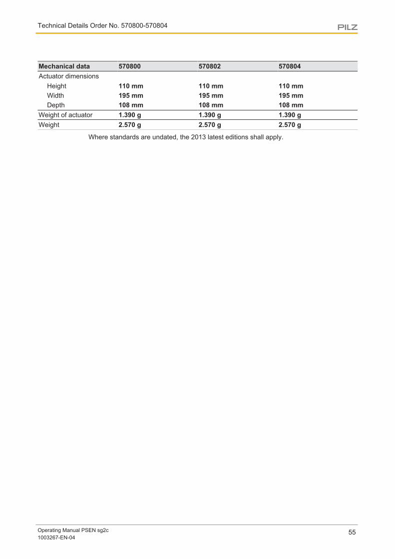
Mechanical data 570800 570802 570804Actuator dimensions
Height 110 mm 110 mm 110 mmWidth 195 mm 195 mm 195 mmDepth 108 mm 108 mm 108 mm
Weight of actuator 1.390 g 1.390 g 1.390 gWeight 2.570 g 2.570 g 2.570 g
Where standards are undated, the 2013 latest editions shall apply.

Technical Details Order No. 570806-570810
Operating Manual PSEN sg2c1003267-EN-04
56
11 Technical Details Order No. 570806-570810
General 570806 570808 570810Approvals CE, FCC, TÜV, UL/cUL CE, FCC, TÜV, UL/cUL CE, FCC, TÜV, UL/cULSensor's mode of opera-tion Transponder Transponder TransponderCoding level in accord-ance with EN ISO 14119 Low Low LowDesign in accordance withEN ISO 14119 4 4 4Pilz coding type Coded Coded CodedElectrical data 570806 570808 570810Supply voltage
Voltage 24 V 24 V 24 VKind DC DC DCVoltage tolerance -15 %/+10 % -15 %/+10 % -15 %/+10 %Output of externalpower supply (DC) 2 W 2 W 2 W
Max. inrush current at UB 5 A 5 A 5 AMax. switching frequency 1 Hz 1 Hz 1 HzMagnet. supply voltage 24 V 24 V 24 VMax. solenoid current t<150 ms 1,5 A 1,5 A 1,5 AMax. cable capacitance atthe safety outputs
No-load, PNOZ with re-lay contacts 40 nF 40 nF 40 nFPNOZmulti, PNOZelog,PSS 70 nF 70 nF 70 nF
Max. inrush current im-pulse
Current pulse, A1 5 A 5 A 5 APulse duration, A1 0,0002 ms 0,0002 ms 0,0002 ms
Max. unit fuse protectionin accordance with UL 3 A 3 A 3 AInputs 570806 570808 570810Number 2 2 2Voltage at inputs 24 V DC 24 V DC 24 V DCInput current range 5 mA 5 mA 5 mASection stop 570806 570808 570810Number of N/C contacts 2 – –Release type Turn release – –

Technical Details Order No. 570806-570810
Operating Manual PSEN sg2c1003267-EN-04
57
Section stop 570806 570808 570810Utilisation category
In accordance with thestandard EN 60947-5-1 – –Contacts, AC15 at 24 V – –Max. current 1,5 A – –Contacts, DC13 at 24 V – –Max. current 1,5 A – –
Mechanical life 6050 cycles – –Signal output
Output voltage 24 V – –Max. current 100 mA – –
Semiconductor outputs 570806 570808 570810OSSD safety outputs 2 2 2Signal outputs 2 2 2Switching current per out-put 500 mA 500 mA 500 mABreaking capacity per out-put 12 W 12 W 12 WResidual current at "0"signal 0,5 mA 0,5 mA 0,5 mAShort circuit-proof yes yes yesPushbuttons 570806 570808 570810Utilisation category
In accordance with thestandard EN 60947-5-1 EN 60947-5-1 EN 60947-5-1Contacts, AC12 at 24 V 24 V 24 VMax. current 0,1 A 0,1 A 0,1 AContacts, DC12 at 24 V 24 V 24 VMax. current 0,1 A 0,1 A 0,1 A
Electrical life 1,000,000 cycles 1,000,000 cycles 1,000,000 cyclesMechanical life 1,000,000 cycles 1,000,000 cycles 1,000,000 cyclesContact material AgNi AgNi AgNiTimes 570806 570808 570810Test pulse duration, safetyoutputs 450 µs 450 µs 450 µsSwitch-on delay
after UB is applied 1,1 s 1,1 s 1,1 sInputs typ. 15 ms 15 ms 15 msInputs max. 20 ms 20 ms 20 msActuator typ. 90 ms 90 ms 90 msActuator max. 120 ms 120 ms 120 ms
Delay-on de-energisationInputs typ. 15 ms 15 ms 15 msInputs max. 20 ms 20 ms 20 msActuator typ. 30 ms 30 ms 30 msActuator max. 260 ms 260 ms 260 ms

Technical Details Order No. 570806-570810
Operating Manual PSEN sg2c1003267-EN-04
58
Times 570806 570808 570810Supply interruption beforede-energisation 20 ms 20 ms 20 msSimultaneity, channel 1and 2 max. 7 ms 7 ms 7 msEnvironmental data 570806 570808 570810Temperature of metal sur-face at ambient temperat-ure: 25 °C 40 °C 40 °C 40 °CAmbient temperature
In accordance with thestandard EN 60068-2-14 EN 60068-2-14 EN 60068-2-14Temperature range -20 - 55 °C -20 - 55 °C -20 - 55 °C
Storage temperatureIn accordance with thestandard EN 60068-2-1/-2 EN 60068-2-1/-2 EN 60068-2-1/-2Temperature range -25 - 70 °C -25 - 70 °C -25 - 70 °C
Climatic suitabilityIn accordance with thestandard EN 60068-2-78 EN 60068-2-78 EN 60068-2-78Humidity 93 % r. h. at 40 °C 93 % r. h. at 40 °C 93 % r. h. at 40 °C
EMC EN 55011: class A, EN61000-4-2, EN 61000-4-3,EN 61000-4-4, EN61000-4-5, EN 61000-4-6,EN 61000-4-8
EN 55011: class A, EN61000-4-2, EN 61000-4-3,EN 61000-4-4, EN61000-4-5, EN 61000-4-6,EN 61000-4-8
EN 55011: class A, EN61000-4-2, EN 61000-4-3,EN 61000-4-4, EN61000-4-5, EN 61000-4-6,EN 61000-4-8
VibrationIn accordance with thestandard EN 60068-2-6 EN 60068-2-6 EN 60068-2-6Frequency 10 - 55 Hz 10 - 55 Hz 10 - 55 HzAmplitude 1 mm 1 mm 1 mm
Shock stressIn accordance with thestandard EN 60068-2-27 EN 60068-2-27 EN 60068-2-27Acceleration 30g 30g 30gDuration 11 ms 11 ms 11 ms
Airgap creepageOvervoltage category III III IIIPollution degree 3 3 3
Rated insulation voltage 30 V 30 V 30 VRated impulse withstandvoltage 1 kV 1 kV 1 kVProtection type
Housing IP54 IP54 IP54Mechanical data 570806 570808 570810Escape release available yes yes yesMechanical life 200,000 cycles 200,000 cycles 200,000 cyclesMax. holding force in clos-ing direction 1000 N 1000 N 1000 N

Technical Details Order No. 570806-570810
Operating Manual PSEN sg2c1003267-EN-04
59
Mechanical data 570806 570808 570810Max. holding force in pandirection 2000 N 2000 N 2000 NMax. vertical offset +/-2,5 mm +/-2,5 mm +/-2,5 mmMax. lateral offset +/-3,0 mm +/-3,0 mm +/-3,0 mmMax. angular offset +/-1,5 deg +/-1,5 deg +/-1,5 degMax. retract speed of ac-tuator 0,5 m/s 0,5 m/s 0,5 m/sActuator 1 PSEN sg2 actuator PSEN sg2 actuator PSEN sg2 actuatorOperating distances
Assured operating dis-tance Sao 2 mm 2 mm 2 mmMin. operating distanceSomin 3 mm 3 mm 3 mmTypical operating dis-tance So 3 mm 3 mm 3 mmAssured release dis-tance Sar 4 mm 4 mm 4 mmChange of operatingdistance with temperat-ure changes +-0,01mm/°C +-0,01mm/°C +-0,01mm/°CTyp. Hysteresis 0,1 mm 0,1 mm 0,1 mm
Connection type Spring-loaded terminal,plug-in
Spring-loaded terminal,plug-in
Spring-loaded terminal,plug-in
Cable LiYY 24 x 0.5 mm2 LiYY 24 x 0.5 mm2 LiYY 24 x 0.5 mm2Material
Top Valox 553 Valox 553 Valox 553Actuator Stainless steel 1.4301 Stainless steel 1.4301 Stainless steel 1.4301
DimensionsHeight 465 mm 465 mm 465 mmWidth 200 mm 200 mm 200 mmDepth 108 mm 108 mm 108 mm
Actuator dimensionsHeight 110 mm 110 mm 110 mmWidth 195 mm 195 mm 195 mmDepth 108 mm 108 mm 108 mm
Weight of actuator 1.390 g 1.390 g 1.390 gWeight 2.570 g 2.570 g 2.570 g
Where standards are undated, the 2013 latest editions shall apply.

Technical Details Order No. 570812-570816
Operating Manual PSEN sg2c1003267-EN-04
60
12 Technical Details Order No. 570812-570816
General 570812 570814 570816Approvals CE, FCC, TÜV, UL/cUL CE, FCC, TÜV, UL/cUL CE, FCC, TÜV, UL/cULSensor's mode of opera-tion Transponder Transponder TransponderCoding level in accord-ance with EN ISO 14119 Low Low LowDesign in accordance withEN ISO 14119 4 4 4Pilz coding type Coded Coded CodedElectrical data 570812 570814 570816Supply voltage
Voltage 24 V 24 V 24 VKind DC DC DCVoltage tolerance -15 %/+10 % -15 %/+10 % -15 %/+10 %Output of externalpower supply (DC) 2 W 2 W 2 W
Max. inrush current at UB 5 A 5 A 5 AMax. switching frequency 1 Hz 1 Hz 1 HzMagnet. supply voltage 24 V 24 V 24 VMax. solenoid current t<150 ms 1,5 A 1,5 A 1,5 AMax. cable capacitance atthe safety outputs
No-load, PNOZ with re-lay contacts 40 nF 40 nF 40 nFPNOZmulti, PNOZelog,PSS 70 nF 70 nF 70 nF
Max. inrush current im-pulse
Current pulse, A1 5 A 5 A 5 APulse duration, A1 0,0002 ms 0,0002 ms 0,0002 ms
Max. unit fuse protectionin accordance with UL 3 A 3 A 3 AInputs 570812 570814 570816Number 2 2 2Voltage at inputs 24 V DC 24 V DC 24 V DCInput current range 5 mA 5 mA 5 mAE-STOP 570812 570814 570816Number of N/C contacts 2 2 –E-STOP release type Turn release Turn release –

Technical Details Order No. 570812-570816
Operating Manual PSEN sg2c1003267-EN-04
61
E-STOP 570812 570814 570816Utilisation category
In accordance with thestandard EN 60947-5-1 EN 60947-5-1 –Contacts, AC15 at 24 V 24 V –Current 1,5 A 1,5 A –Contacts, DC13 at 24 V 24 V –Current 1,5 A 1,5 A –
Mechanical life 6050 cycles 6050 cycles –Signal output
Output voltage 24 V 24 V –Max. current 100 mA 100 mA –
Section stop 570812 570814 570816Number of N/C contacts – – 2Release type – – Turn releaseUtilisation category
In accordance with thestandard – – EN 60947-5-1Contacts, AC15 at – – 24 VMax. current – – 1,5 AContacts, DC13 at – – 24 VMax. current – – 1,5 A
Mechanical life – – 6050 cyclesSignal output
Output voltage – – 24 VMax. current – – 100 mA
Semiconductor outputs 570812 570814 570816OSSD safety outputs 2 2 2Signal outputs 2 2 2Switching current per out-put 500 mA 500 mA 500 mABreaking capacity per out-put 12 W 12 W 12 WResidual current at "0"signal 0,5 mA 0,5 mA 0,5 mAShort circuit-proof yes yes yesPushbuttons 570812 570814 570816Utilisation category
In accordance with thestandard EN 60947-5-1 EN 60947-5-1 EN 60947-5-1Contacts, AC12 at 24 V 24 V 24 VMax. current 0,1 A 0,1 A 0,1 AContacts, DC12 at 24 V 24 V 24 VMax. current 0,1 A 0,1 A 0,1 A
Electrical life 1,000,000 cycles 1,000,000 cycles 1,000,000 cyclesMechanical life 1,000,000 cycles 1,000,000 cycles 1,000,000 cyclesContact material AgNi AgNi AgNi

Technical Details Order No. 570812-570816
Operating Manual PSEN sg2c1003267-EN-04
62
Times 570812 570814 570816Test pulse duration, safetyoutputs 450 µs 450 µs 450 µsSwitch-on delay
after UB is applied 1,1 s 1,1 s 1,1 sInputs typ. 15 ms 15 ms 15 msInputs max. 20 ms 20 ms 20 msActuator typ. 90 ms 90 ms 90 msActuator max. 120 ms 120 ms 120 ms
Delay-on de-energisationInputs typ. 15 ms 15 ms 15 msInputs max. 20 ms 20 ms 20 msActuator typ. 30 ms 30 ms 30 msActuator max. 260 ms 260 ms 260 ms
Supply interruption beforede-energisation 20 ms 20 ms 20 msSimultaneity, channel 1and 2 max. 7 ms 7 ms 7 msEnvironmental data 570812 570814 570816Temperature of metal sur-face at ambient temperat-ure: 25 °C 40 °C 40 °C 40 °CAmbient temperature
In accordance with thestandard EN 60068-2-14 EN 60068-2-14 EN 60068-2-14Temperature range -20 - 55 °C -20 - 55 °C -20 - 55 °C
Storage temperatureIn accordance with thestandard EN 60068-2-1/-2 EN 60068-2-1/-2 EN 60068-2-1/-2Temperature range -25 - 70 °C -25 - 70 °C -25 - 70 °C
Climatic suitabilityIn accordance with thestandard EN 60068-2-78 EN 60068-2-78 EN 60068-2-78Humidity 93 % r. h. at 40 °C 93 % r. h. at 40 °C 93 % r. h. at 40 °C
EMC EN 55011: class A, EN61000-4-2, EN 61000-4-3,EN 61000-4-4, EN61000-4-5, EN 61000-4-6,EN 61000-4-8
EN 55011: class A, EN61000-4-2, EN 61000-4-3,EN 61000-4-4, EN61000-4-5, EN 61000-4-6,EN 61000-4-8
EN 55011: class A, EN61000-4-2, EN 61000-4-3,EN 61000-4-4, EN61000-4-5, EN 61000-4-6,EN 61000-4-8
VibrationIn accordance with thestandard EN 60068-2-6 EN 60068-2-6 EN 60068-2-6Frequency 10 - 55 Hz 10 - 55 Hz 10 - 55 HzAmplitude 1 mm 1 mm 1 mm
Shock stressIn accordance with thestandard EN 60068-2-27 EN 60068-2-27 EN 60068-2-27Acceleration 30g 30g 30gDuration 11 ms 11 ms 11 ms

Technical Details Order No. 570812-570816
Operating Manual PSEN sg2c1003267-EN-04
63
Environmental data 570812 570814 570816Airgap creepage
Overvoltage category III III IIIPollution degree 3 3 3
Rated insulation voltage 30 V 30 V 30 VRated impulse withstandvoltage 1 kV 1 kV 1 kVProtection type
Housing IP54 IP54 IP54Mechanical data 570812 570814 570816Escape release available yes yes yesMechanical life 200,000 cycles 200,000 cycles 200,000 cyclesMax. holding force in clos-ing direction 1000 N 1000 N 1000 NMax. holding force in pandirection 2000 N 2000 N 2000 NMax. vertical offset +/-2,5 mm +/-2,5 mm +/-2,5 mmMax. lateral offset +/-3,0 mm +/-3,0 mm +/-3,0 mmMax. angular offset +/-1,5 deg +/-1,5 deg +/-1,5 degMax. retract speed of ac-tuator 0,5 m/s 0,5 m/s 0,5 m/sActuator 1 PSEN sg2 actuator PSEN sg2 actuator PSEN sg2 actuatorOperating distances
Assured operating dis-tance Sao 2 mm 2 mm 2 mmMin. operating distanceSomin 3 mm 3 mm 3 mmTypical operating dis-tance So 3 mm 3 mm 3 mmAssured release dis-tance Sar 4 mm 4 mm 4 mmChange of operatingdistance with temperat-ure changes +-0,01mm/°C +-0,01mm/°C +-0,01mm/°CTyp. Hysteresis 0,1 mm 0,1 mm 0,1 mm
Connection type Spring-loaded terminal,plug-in
Spring-loaded terminal,plug-in
Spring-loaded terminal,plug-in
Cable LiYY 24 x 0.5 mm2 LiYY 24 x 0.5 mm2 LiYY 24 x 0.5 mm2Material
Top Valox 553 Valox 553 Valox 553Actuator Stainless steel 1.4301 Stainless steel 1.4301 Stainless steel 1.4301
DimensionsHeight 555 mm 555 mm 555 mmWidth 200 mm 200 mm 200 mmDepth 108 mm 108 mm 108 mm

Technical Details Order No. 570812-570816
Operating Manual PSEN sg2c1003267-EN-04
64
Mechanical data 570812 570814 570816Actuator dimensions
Height 110 mm 110 mm 110 mmWidth 195 mm 195 mm 195 mmDepth 108 mm 108 mm 108 mm
Weight of actuator 1.390 g 1.390 g 1.390 gWeight 2.670 g 2.670 g 2.670 g
Where standards are undated, the 2013 latest editions shall apply.
Technical Details Order No. 570818-570822
Operating Manual PSEN sg2c1003267-EN-04
65
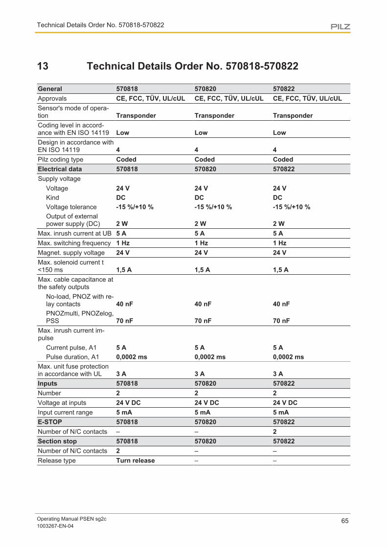
13 Technical Details Order No. 570818-570822
General 570818 570820 570822Approvals CE, FCC, TÜV, UL/cUL CE, FCC, TÜV, UL/cUL CE, FCC, TÜV, UL/cULSensor's mode of opera-tion Transponder Transponder TransponderCoding level in accord-ance with EN ISO 14119 Low Low LowDesign in accordance withEN ISO 14119 4 4 4Pilz coding type Coded Coded CodedElectrical data 570818 570820 570822Supply voltage
Voltage 24 V 24 V 24 VKind DC DC DCVoltage tolerance -15 %/+10 % -15 %/+10 % -15 %/+10 %Output of externalpower supply (DC) 2 W 2 W 2 W
Max. inrush current at UB 5 A 5 A 5 AMax. switching frequency 1 Hz 1 Hz 1 HzMagnet. supply voltage 24 V 24 V 24 VMax. solenoid current t<150 ms 1,5 A 1,5 A 1,5 AMax. cable capacitance atthe safety outputs
No-load, PNOZ with re-lay contacts 40 nF 40 nF 40 nFPNOZmulti, PNOZelog,PSS 70 nF 70 nF 70 nF
Max. inrush current im-pulse
Current pulse, A1 5 A 5 A 5 APulse duration, A1 0,0002 ms 0,0002 ms 0,0002 ms
Max. unit fuse protectionin accordance with UL 3 A 3 A 3 AInputs 570818 570820 570822Number 2 2 2Voltage at inputs 24 V DC 24 V DC 24 V DCInput current range 5 mA 5 mA 5 mAE-STOP 570818 570820 570822Number of N/C contacts – – 2Section stop 570818 570820 570822Number of N/C contacts 2 – –Release type Turn release – –

Technical Details Order No. 570818-570822
Operating Manual PSEN sg2c1003267-EN-04
66
Section stop 570818 570820 570822Utilisation category
In accordance with thestandard EN 60947-5-1 – –Contacts, AC15 at 24 V – –Max. current 1,5 A – –Contacts, DC13 at 24 V – –Max. current 1,5 A – –
Mechanical life 6050 cycles – –Signal output
Output voltage 24 V – –Max. current 100 mA – –
Semiconductor outputs 570818 570820 570822OSSD safety outputs 2 2 2Signal outputs 2 2 2Switching current per out-put 500 mA 500 mA 500 mABreaking capacity per out-put 12 W 12 W 12 WResidual current at "0"signal 0,5 mA 0,5 mA 0,5 mAShort circuit-proof yes yes yesPushbuttons 570818 570820 570822Utilisation category
In accordance with thestandard EN 60947-5-1 EN 60947-5-1 EN 60947-5-1Contacts, AC12 at 24 V 24 V 24 VMax. current 0,1 A 0,1 A 0,1 AContacts, DC12 at 24 V 24 V 24 VMax. current 0,1 A 0,1 A 0,1 A
Electrical life 1,000,000 cycles 1,000,000 cycles 1,000,000 cyclesMechanical life 1,000,000 cycles 1,000,000 cycles 1,000,000 cyclesContact material AgNi AgNi AgNiTimes 570818 570820 570822Test pulse duration, safetyoutputs 450 µs 450 µs 450 µsSwitch-on delay
after UB is applied 1,1 s 1,1 s 1,1 sInputs typ. 15 ms 15 ms 15 msInputs max. 20 ms 20 ms 20 msActuator typ. 90 ms 90 ms 90 msActuator max. 120 ms 120 ms 120 ms
Delay-on de-energisationInputs typ. 15 ms 15 ms 15 msInputs max. 20 ms 20 ms 20 msActuator typ. 30 ms 30 ms 30 msActuator max. 260 ms 260 ms 260 ms

Technical Details Order No. 570818-570822
Operating Manual PSEN sg2c1003267-EN-04
67
Times 570818 570820 570822Supply interruption beforede-energisation 20 ms 20 ms 20 msSimultaneity, channel 1and 2 max. 7 ms 7 ms 7 msEnvironmental data 570818 570820 570822Temperature of metal sur-face at ambient temperat-ure: 25 °C 40 °C 40 °C 40 °CAmbient temperature
In accordance with thestandard EN 60068-2-14 EN 60068-2-14 EN 60068-2-14Temperature range -20 - 55 °C -20 - 55 °C -20 - 55 °C
Storage temperatureIn accordance with thestandard EN 60068-2-1/-2 EN 60068-2-1/-2 EN 60068-2-1/-2Temperature range -25 - 70 °C -25 - 70 °C -25 - 70 °C
Climatic suitabilityIn accordance with thestandard EN 60068-2-78 EN 60068-2-78 EN 60068-2-78Humidity 93 % r. h. at 40 °C 93 % r. h. at 40 °C 93 % r. h. at 40 °C
EMC EN 55011: class A, EN61000-4-2, EN 61000-4-3,EN 61000-4-4, EN61000-4-5, EN 61000-4-6,EN 61000-4-8
EN 55011: class A, EN61000-4-2, EN 61000-4-3,EN 61000-4-4, EN61000-4-5, EN 61000-4-6,EN 61000-4-8
EN 55011: class A, EN61000-4-2, EN 61000-4-3,EN 61000-4-4, EN61000-4-5, EN 61000-4-6,EN 61000-4-8
VibrationIn accordance with thestandard EN 60068-2-6 EN 60068-2-6 EN 60068-2-6Frequency 10 - 55 Hz 10 - 55 Hz 10 - 55 HzAmplitude 1 mm 1 mm 1 mm
Shock stressIn accordance with thestandard EN 60068-2-27 EN 60068-2-27 EN 60068-2-27Acceleration 30g 30g 30gDuration 11 ms 11 ms 11 ms
Airgap creepageOvervoltage category III III IIIPollution degree 3 3 3
Rated insulation voltage 30 V 30 V 30 VRated impulse withstandvoltage 1 kV 1 kV 1 kVProtection type
Housing IP54 IP54 IP54Mechanical data 570818 570820 570822Escape release available yes yes yesMechanical life 200,000 cycles 200,000 cycles 200,000 cyclesMax. holding force in clos-ing direction 1000 N 1000 N 1000 N

Technical Details Order No. 570818-570822
Operating Manual PSEN sg2c1003267-EN-04
68
Mechanical data 570818 570820 570822Max. holding force in pandirection 2000 N 2000 N 2000 NMax. vertical offset +/-2,5 mm +/-2,5 mm +/-2,5 mmMax. lateral offset +/-3,0 mm +/-3,0 mm +/-3,0 mmMax. angular offset +/-1,5 deg +/-1,5 deg +/-1,5 degMax. retract speed of ac-tuator 0,5 m/s 0,5 m/s 0,5 m/sActuator 1 PSEN sg2 actuator PSEN sg2 actuator PSEN sg2 actuatorOperating distances
Assured operating dis-tance Sao 2 mm 2 mm 2 mmMin. operating distanceSomin 3 mm 3 mm 3 mmTypical operating dis-tance So 3 mm 3 mm 3 mmAssured release dis-tance Sar 4 mm 4 mm 4 mmChange of operatingdistance with temperat-ure changes +-0,01mm/°C +-0,01mm/°C +-0,01mm/°CTyp. Hysteresis 0,1 mm 0,1 mm 0,1 mm
Connection type Spring-loaded terminal,plug-in
Spring-loaded terminal,plug-in
Spring-loaded terminal,plug-in
Cable LiYY 24 x 0.5 mm2 LiYY 24 x 0.5 mm2 LiYY 24 x 0.5 mm2Material
Top Valox 553 Valox 553 Valox 553Actuator Stainless steel 1.4301 Stainless steel 1.4301 Stainless steel 1.4301
DimensionsHeight 555 mm 555 mm 555 mmWidth 200 mm 200 mm 200 mmDepth 108 mm 108 mm 108 mm
Actuator dimensionsHeight 110 mm 110 mm 110 mmWidth 195 mm 195 mm 195 mmDepth 108 mm 108 mm 108 mm
Weight of actuator 1.390 g 1.390 g 1.390 gWeight 2.670 g 2.670 g 2.670 g
Where standards are undated, the 2013 latest editions shall apply.

Technical Details Order No. 570824-570828
Operating Manual PSEN sg2c1003267-EN-04
69
14 Technical Details Order No. 570824-570828
General 570824 570826 570828Approvals CE, FCC, TÜV, UL/cUL CE, FCC, TÜV, UL/cUL CE, FCC, TÜV, UL/cULSensor's mode of opera-tion Transponder Transponder TransponderCoding level in accord-ance with EN ISO 14119 Low Low LowDesign in accordance withEN ISO 14119 4 4 4Pilz coding type Coded Coded CodedElectrical data 570824 570826 570828Supply voltage
Voltage 24 V 24 V 24 VKind DC DC DCVoltage tolerance -15 %/+10 % -15 %/+10 % -15 %/+10 %Output of externalpower supply (DC) 2 W 2 W 2 W
Max. inrush current at UB 5 A 5 A 5 AMax. switching frequency 1 Hz 1 Hz 1 HzMagnet. supply voltage 24 V 24 V 24 VMax. solenoid current t<150 ms 1,5 A 1,5 A 1,5 AMax. cable capacitance atthe safety outputs
No-load, PNOZ with re-lay contacts 40 nF 40 nF 40 nFPNOZmulti, PNOZelog,PSS 70 nF 70 nF 70 nF
Max. inrush current im-pulse
Current pulse, A1 5 A 5 A 5 APulse duration, A1 0,0002 ms 0,0002 ms 0,0002 ms
Max. unit fuse protectionin accordance with UL 3 A 3 A 3 AInputs 570824 570826 570828Number 2 2 2Voltage at inputs 24 V DC 24 V DC 24 V DCInput current range 5 mA 5 mA 5 mAE-STOP 570824 570826 570828Number of N/C contacts 2 2 –E-STOP release type Turn release Turn release –

Technical Details Order No. 570824-570828
Operating Manual PSEN sg2c1003267-EN-04
70
E-STOP 570824 570826 570828Utilisation category
In accordance with thestandard EN 60947-5-1 EN 60947-5-1 –Contacts, AC15 at 24 V 24 V –Current 1,5 A 1,5 A –Contacts, DC13 at 24 V 24 V –Current 1,5 A 1,5 A –
Mechanical life 6050 cycles 6050 cycles –Signal output
Output voltage 24 V 24 V –Max. current 100 mA 100 mA –
Section stop 570824 570826 570828Number of N/C contacts – – 2Release type – – Turn releaseUtilisation category
In accordance with thestandard – – EN 60947-5-1Contacts, AC15 at – – 24 VMax. current – – 1,5 AContacts, DC13 at – – 24 VMax. current – – 1,5 A
Mechanical life – – 6050 cyclesSignal output
Output voltage – – 24 VMax. current – – 100 mA
Semiconductor outputs 570824 570826 570828OSSD safety outputs 2 2 2Signal outputs 2 2 2Switching current per out-put 500 mA 500 mA 500 mABreaking capacity per out-put 12 W 12 W 12 WResidual current at "0"signal 0,5 mA 0,5 mA 0,5 mAShort circuit-proof yes yes yesPushbuttons 570824 570826 570828Utilisation category
In accordance with thestandard EN 60947-5-1 EN 60947-5-1 EN 60947-5-1Contacts, AC12 at 24 V 24 V 24 VMax. current 0,1 A 0,1 A 0,1 AContacts, DC12 at 24 V 24 V 24 VMax. current 0,1 A 0,1 A 0,1 A
Electrical life 1,000,000 cycles 1,000,000 cycles 1,000,000 cyclesMechanical life 1,000,000 cycles 1,000,000 cycles 1,000,000 cyclesContact material AgNi AgNi AgNi

Technical Details Order No. 570824-570828
Operating Manual PSEN sg2c1003267-EN-04
71
Times 570824 570826 570828Test pulse duration, safetyoutputs 450 µs 450 µs 450 µsSwitch-on delay
after UB is applied 1,1 s 1,1 s 1,1 sInputs typ. 15 ms 15 ms 15 msInputs max. 20 ms 20 ms 20 msActuator typ. 90 ms 90 ms 90 msActuator max. 120 ms 120 ms 120 ms
Delay-on de-energisationInputs typ. 15 ms 15 ms 15 msInputs max. 20 ms 20 ms 20 msActuator typ. 30 ms 30 ms 30 msActuator max. 260 ms 260 ms 260 ms
Supply interruption beforede-energisation 20 ms 20 ms 20 msSimultaneity, channel 1and 2 max. 7 ms 7 ms 7 msEnvironmental data 570824 570826 570828Temperature of metal sur-face at ambient temperat-ure: 25 °C 40 °C 40 °C 40 °CAmbient temperature
In accordance with thestandard EN 60068-2-14 EN 60068-2-14 EN 60068-2-14Temperature range -20 - 55 °C -20 - 55 °C -20 - 55 °C
Storage temperatureIn accordance with thestandard EN 60068-2-1/-2 EN 60068-2-1/-2 EN 60068-2-1/-2Temperature range -25 - 70 °C -25 - 70 °C -25 - 70 °C
Climatic suitabilityIn accordance with thestandard EN 60068-2-78 EN 60068-2-78 EN 60068-2-78Humidity 93 % r. h. at 40 °C 93 % r. h. at 40 °C 93 % r. h. at 40 °C
EMC EN 55011: class A, EN61000-4-2, EN 61000-4-3,EN 61000-4-4, EN61000-4-5, EN 61000-4-6,EN 61000-4-8
EN 55011: class A, EN61000-4-2, EN 61000-4-3,EN 61000-4-4, EN61000-4-5, EN 61000-4-6,EN 61000-4-8
EN 55011: class A, EN61000-4-2, EN 61000-4-3,EN 61000-4-4, EN61000-4-5, EN 61000-4-6,EN 61000-4-8
VibrationIn accordance with thestandard EN 60068-2-6 EN 60068-2-6 EN 60068-2-6Frequency 10 - 55 Hz 10 - 55 Hz 10 - 55 HzAmplitude 1 mm 1 mm 1 mm
Shock stressIn accordance with thestandard EN 60068-2-27 EN 60068-2-27 EN 60068-2-27Acceleration 30g 30g 30gDuration 11 ms 11 ms 11 ms

Technical Details Order No. 570824-570828
Operating Manual PSEN sg2c1003267-EN-04
72
Environmental data 570824 570826 570828Airgap creepage
Overvoltage category III III IIIPollution degree 3 3 3
Rated insulation voltage 30 V 30 V 30 VRated impulse withstandvoltage 1 kV 1 kV 1 kVProtection type
Housing IP54 IP54 IP54Mechanical data 570824 570826 570828Escape release available yes yes yesMechanical life 200,000 cycles 200,000 cycles 200,000 cyclesMax. holding force in clos-ing direction 1000 N 1000 N 1000 NMax. holding force in pandirection 2000 N 2000 N 2000 NMax. vertical offset +/-2,5 mm +/-2,5 mm +/-2,5 mmMax. lateral offset +/-3,0 mm +/-3,0 mm +/-3,0 mmMax. angular offset +/-1,5 deg +/-1,5 deg +/-1,5 degMax. retract speed of ac-tuator 0,5 m/s 0,5 m/s 0,5 m/sActuator 1 PSEN sg2 actuator PSEN sg2 actuator PSEN sg2 actuatorOperating distances
Assured operating dis-tance Sao 2 mm 2 mm 2 mmMin. operating distanceSomin 3 mm 3 mm 3 mmTypical operating dis-tance So 3 mm 3 mm 3 mmAssured release dis-tance Sar 4 mm 4 mm 4 mmChange of operatingdistance with temperat-ure changes +-0,01mm/°C +-0,01mm/°C +-0,01mm/°CTyp. Hysteresis 0,1 mm 0,1 mm 0,1 mm
Connection type Spring-loaded terminal,plug-in
Spring-loaded terminal,plug-in
Spring-loaded terminal,plug-in
Cable LiYY 24 x 0.5 mm2 LiYY 24 x 0.5 mm2 LiYY 24 x 0.5 mm2Material
Top Valox 553 Valox 553 Valox 553Actuator Stainless steel 1.4301 Stainless steel 1.4301 Stainless steel 1.4301
DimensionsHeight 568 mm 568 mm 568 mmWidth 200 mm 200 mm 200 mmDepth 108 mm 108 mm 108 mm

Technical Details Order No. 570824-570828
Operating Manual PSEN sg2c1003267-EN-04
73
Mechanical data 570824 570826 570828Actuator dimensions
Height 110 mm 110 mm 110 mmWidth 195 mm 195 mm 195 mmDepth 108 mm 108 mm 108 mm
Weight of actuator 1.390 g 1.390 g 1.390 gWeight 2.690 g 2.690 g 2.690 g
Where standards are undated, the 2013 latest editions shall apply.
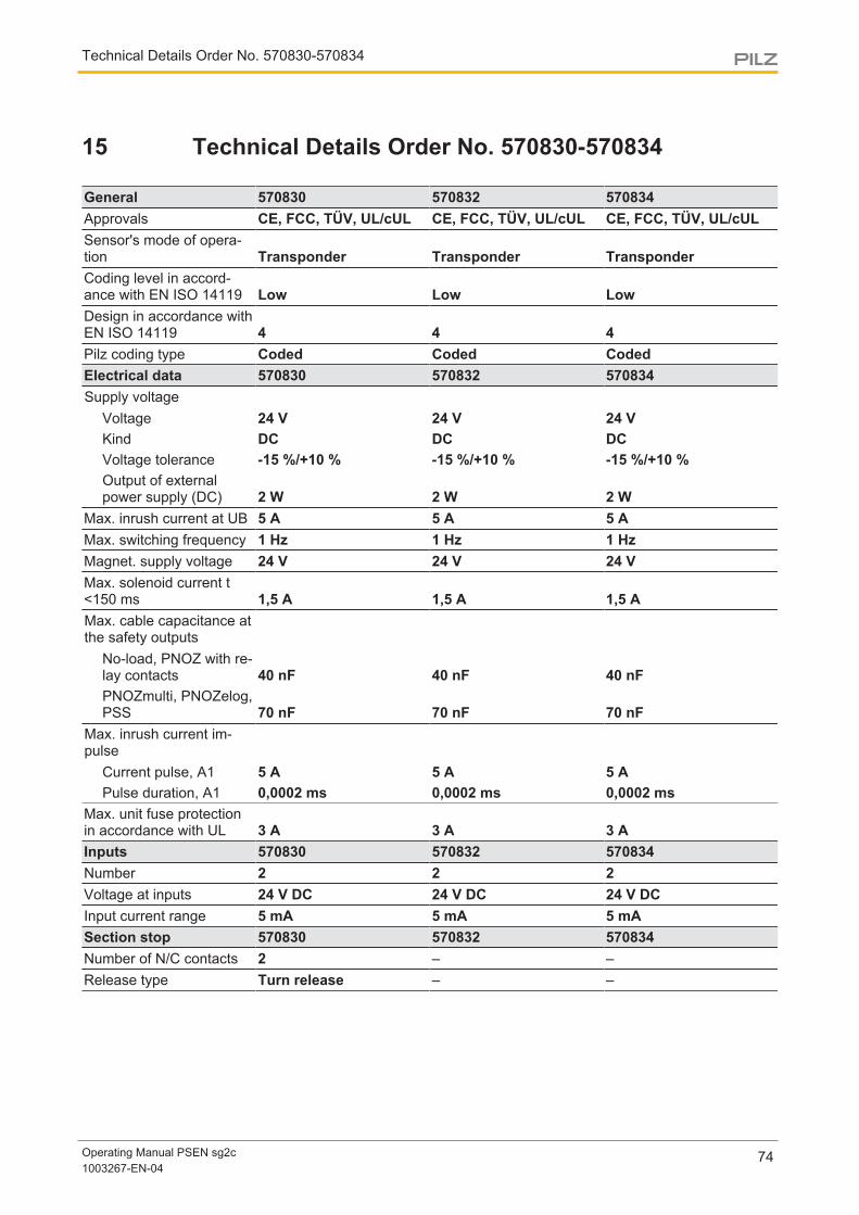
Technical Details Order No. 570830-570834
Operating Manual PSEN sg2c1003267-EN-04
74
15 Technical Details Order No. 570830-570834
General 570830 570832 570834Approvals CE, FCC, TÜV, UL/cUL CE, FCC, TÜV, UL/cUL CE, FCC, TÜV, UL/cULSensor's mode of opera-tion Transponder Transponder TransponderCoding level in accord-ance with EN ISO 14119 Low Low LowDesign in accordance withEN ISO 14119 4 4 4Pilz coding type Coded Coded CodedElectrical data 570830 570832 570834Supply voltage
Voltage 24 V 24 V 24 VKind DC DC DCVoltage tolerance -15 %/+10 % -15 %/+10 % -15 %/+10 %Output of externalpower supply (DC) 2 W 2 W 2 W
Max. inrush current at UB 5 A 5 A 5 AMax. switching frequency 1 Hz 1 Hz 1 HzMagnet. supply voltage 24 V 24 V 24 VMax. solenoid current t<150 ms 1,5 A 1,5 A 1,5 AMax. cable capacitance atthe safety outputs
No-load, PNOZ with re-lay contacts 40 nF 40 nF 40 nFPNOZmulti, PNOZelog,PSS 70 nF 70 nF 70 nF
Max. inrush current im-pulse
Current pulse, A1 5 A 5 A 5 APulse duration, A1 0,0002 ms 0,0002 ms 0,0002 ms
Max. unit fuse protectionin accordance with UL 3 A 3 A 3 AInputs 570830 570832 570834Number 2 2 2Voltage at inputs 24 V DC 24 V DC 24 V DCInput current range 5 mA 5 mA 5 mASection stop 570830 570832 570834Number of N/C contacts 2 – –Release type Turn release – –

Technical Details Order No. 570830-570834
Operating Manual PSEN sg2c1003267-EN-04
75
Section stop 570830 570832 570834Utilisation category
In accordance with thestandard EN 60947-5-1 – –Contacts, AC15 at 24 V – –Max. current 1,5 A – –Contacts, DC13 at 24 V – –Max. current 1,5 A – –
Mechanical life 6050 cycles – –Signal output
Output voltage 24 V – –Max. current 100 mA – –
Semiconductor outputs 570830 570832 570834OSSD safety outputs 2 2 2Signal outputs 2 2 2Switching current per out-put 500 mA 500 mA 500 mABreaking capacity per out-put 12 W 12 W 12 WResidual current at "0"signal 0,5 mA 0,5 mA 0,5 mAShort circuit-proof yes yes yesPushbuttons 570830 570832 570834Utilisation category
In accordance with thestandard EN 60947-5-1 EN 60947-5-1 EN 60947-5-1Contacts, AC12 at 24 V 24 V 24 VMax. current 0,1 A 0,1 A 0,1 AContacts, DC12 at 24 V 24 V 24 VMax. current 0,1 A 0,1 A 0,1 A
Electrical life 1,000,000 cycles 1,000,000 cycles 1,000,000 cyclesMechanical life 1,000,000 cycles 1,000,000 cycles 1,000,000 cyclesContact material AgNi AgNi AgNiTimes 570830 570832 570834Test pulse duration, safetyoutputs 450 µs 450 µs 450 µsSwitch-on delay
after UB is applied 1,1 s 1,1 s 1,1 sInputs typ. 15 ms 15 ms 15 msInputs max. 20 ms 20 ms 20 msActuator typ. 90 ms 90 ms 90 msActuator max. 120 ms 120 ms 120 ms
Delay-on de-energisationInputs typ. 15 ms 15 ms 15 msInputs max. 20 ms 20 ms 20 msActuator typ. 30 ms 30 ms 30 msActuator max. 260 ms 260 ms 260 ms

Technical Details Order No. 570830-570834
Operating Manual PSEN sg2c1003267-EN-04
76
Times 570830 570832 570834Supply interruption beforede-energisation 20 ms 20 ms 20 msSimultaneity, channel 1and 2 max. 7 ms 7 ms 7 msEnvironmental data 570830 570832 570834Temperature of metal sur-face at ambient temperat-ure: 25 °C 40 °C 40 °C 40 °CAmbient temperature
In accordance with thestandard EN 60068-2-14 EN 60068-2-14 EN 60068-2-14Temperature range -20 - 55 °C -20 - 55 °C -20 - 55 °C
Storage temperatureIn accordance with thestandard EN 60068-2-1/-2 EN 60068-2-1/-2 EN 60068-2-1/-2Temperature range -25 - 70 °C -25 - 70 °C -25 - 70 °C
Climatic suitabilityIn accordance with thestandard EN 60068-2-78 EN 60068-2-78 EN 60068-2-78Humidity 93 % r. h. at 40 °C 93 % r. h. at 40 °C 93 % r. h. at 40 °C
EMC EN 55011: class A, EN61000-4-2, EN 61000-4-3,EN 61000-4-4, EN61000-4-5, EN 61000-4-6,EN 61000-4-8
EN 55011: class A, EN61000-4-2, EN 61000-4-3,EN 61000-4-4, EN61000-4-5, EN 61000-4-6,EN 61000-4-8
EN 55011: class A, EN61000-4-2, EN 61000-4-3,EN 61000-4-4, EN61000-4-5, EN 61000-4-6,EN 61000-4-8
VibrationIn accordance with thestandard EN 60068-2-6 EN 60068-2-6 EN 60068-2-6Frequency 10 - 55 Hz 10 - 55 Hz 10 - 55 HzAmplitude 1 mm 1 mm 1 mm
Shock stressIn accordance with thestandard EN 60068-2-27 EN 60068-2-27 EN 60068-2-27Acceleration 30g 30g 30gDuration 11 ms 11 ms 11 ms
Airgap creepageOvervoltage category III III IIIPollution degree 3 3 3
Rated insulation voltage 30 V 30 V 30 VRated impulse withstandvoltage 1 kV 1 kV 1 kVProtection type
Housing IP54 IP54 IP54Mechanical data 570830 570832 570834Escape release available yes yes yesMechanical life 200,000 cycles 200,000 cycles 200,000 cyclesMax. holding force in clos-ing direction 1000 N 1000 N 1000 N

Technical Details Order No. 570830-570834
Operating Manual PSEN sg2c1003267-EN-04
77
Mechanical data 570830 570832 570834Max. holding force in pandirection 2000 N 2000 N 2000 NMax. vertical offset +/-2,5 mm +/-2,5 mm +/-2,5 mmMax. lateral offset +/-3,0 mm +/-3,0 mm +/-3,0 mmMax. angular offset +/-1,5 deg +/-1,5 deg +/-1,5 degMax. retract speed of ac-tuator 0,5 m/s 0,5 m/s 0,5 m/sActuator 1 PSEN sg2 actuator PSEN sg2 actuator PSEN sg2 actuatorOperating distances
Assured operating dis-tance Sao 2 mm 2 mm 2 mmMin. operating distanceSomin 3 mm 3 mm 3 mmTypical operating dis-tance So 3 mm 3 mm 3 mmAssured release dis-tance Sar 4 mm 4 mm 4 mmChange of operatingdistance with temperat-ure changes +-0,01mm/°C +-0,01mm/°C +-0,01mm/°CTyp. Hysteresis 0,1 mm 0,1 mm 0,1 mm
Connection type Spring-loaded terminal,plug-in
Spring-loaded terminal,plug-in
Spring-loaded terminal,plug-in
Cable LiYY 24 x 0.5 mm2 LiYY 24 x 0.5 mm2 LiYY 24 x 0.5 mm2Material
Top Valox 553 Valox 553 Valox 553Actuator Stainless steel 1.4301 Stainless steel 1.4301 Stainless steel 1.4301
DimensionsHeight 568 mm 568 mm 568 mmWidth 200 mm 200 mm 200 mmDepth 108 mm 108 mm 108 mm
Actuator dimensionsHeight 110 mm 110 mm 110 mmWidth 195 mm 195 mm 195 mmDepth 108 mm 108 mm 108 mm
Weight of actuator 1.390 g 1.390 g 1.390 gWeight 2.690 g 2.690 g 2.690 g
Where standards are undated, the 2013 latest editions shall apply.

Technical Details Order No. 570880-570884
Operating Manual PSEN sg2c1003267-EN-04
78
16 Technical Details Order No. 570880-570884
General 570880 570882 570884Approvals CE, FCC, TÜV, UL/cUL CE, FCC, TÜV, UL/cUL CE, FCC, TÜV, UL/cULSensor's mode of opera-tion Transponder Transponder TransponderCoding level in accord-ance with EN ISO 14119 High High HighDesign in accordance withEN ISO 14119 4 4 4Pilz coding type uniquely coded uniquely coded uniquely codedElectrical data 570880 570882 570884Supply voltage
Voltage 24 V 24 V 24 VKind DC DC DCVoltage tolerance -15 %/+10 % -15 %/+10 % -15 %/+10 %Output of externalpower supply (DC) 2 W 2 W 2 W
Max. inrush current at UB 5 A 5 A 5 AMax. switching frequency 1 Hz 1 Hz 1 HzMagnet. supply voltage 24 V 24 V 24 VMax. solenoid current t<150 ms 1,5 A 1,5 A 1,5 AMax. cable capacitance atthe safety outputs
No-load, PNOZ with re-lay contacts 40 nF 40 nF 40 nFPNOZmulti, PNOZelog,PSS 70 nF 70 nF 70 nF
Max. inrush current im-pulse
Current pulse, A1 5 A 5 A 5 APulse duration, A1 0,0002 ms 0,0002 ms 0,0002 ms
Max. unit fuse protectionin accordance with UL 3 A 3 A 3 AInputs 570880 570882 570884Number 2 2 2Voltage at inputs 24 V DC 24 V DC 24 V DCInput current range 5 mA 5 mA 5 mAE-STOP 570880 570882 570884Number of N/C contacts 2 2 2E-STOP release type Turn release Turn release Turn release

Technical Details Order No. 570880-570884
Operating Manual PSEN sg2c1003267-EN-04
79
E-STOP 570880 570882 570884Utilisation category
In accordance with thestandard EN 60947-5-1 EN 60947-5-1 EN 60947-5-1Contacts, AC15 at 24 V 24 V 24 VCurrent 1,5 A 1,5 A 1,5 AContacts, DC13 at 24 V 24 V 24 VCurrent 1,5 A 1,5 A 1,5 A
Mechanical life 6050 cycles 6050 cycles 6050 cyclesSignal output
Output voltage 24 V 24 V 24 VMax. current 100 mA 100 mA 100 mA
Semiconductor outputs 570880 570882 570884OSSD safety outputs 2 2 2Signal outputs 2 2 2Switching current per out-put 500 mA 500 mA 500 mABreaking capacity per out-put 12 W 12 W 12 WResidual current at "0"signal 0,5 mA 0,5 mA 0,5 mAShort circuit-proof yes yes yesPushbuttons 570880 570882 570884Utilisation category
In accordance with thestandard EN 60947-5-1 EN 60947-5-1 EN 60947-5-1Contacts, AC12 at 24 V 24 V 24 VMax. current 0,1 A 0,1 A 0,1 AContacts, DC12 at 24 V 24 V 24 VMax. current 0,1 A 0,1 A 0,1 A
Electrical life 1,000,000 cycles 1,000,000 cycles 1,000,000 cyclesMechanical life 1,000,000 cycles 1,000,000 cycles 1,000,000 cyclesContact material AgNi AgNi AgNiTimes 570880 570882 570884Test pulse duration, safetyoutputs 450 µs 450 µs 450 µsSwitch-on delay
after UB is applied 1,1 s 1,1 s 1,1 sInputs typ. 15 ms 15 ms 15 msInputs max. 20 ms 20 ms 20 msActuator typ. 90 ms 90 ms 90 msActuator max. 120 ms 120 ms 120 ms
Delay-on de-energisationInputs typ. 15 ms 15 ms 15 msInputs max. 20 ms 20 ms 20 msActuator typ. 30 ms 30 ms 30 msActuator max. 260 ms 260 ms 260 ms

Technical Details Order No. 570880-570884
Operating Manual PSEN sg2c1003267-EN-04
80
Times 570880 570882 570884Supply interruption beforede-energisation 20 ms 20 ms 20 msSimultaneity, channel 1and 2 max. 7 ms 7 ms 7 msEnvironmental data 570880 570882 570884Temperature of metal sur-face at ambient temperat-ure: 25 °C 40 °C 40 °C 40 °CAmbient temperature
In accordance with thestandard EN 60068-2-14 EN 60068-2-14 EN 60068-2-14Temperature range -20 - 55 °C -20 - 55 °C -20 - 55 °C
Storage temperatureIn accordance with thestandard EN 60068-2-1/-2 EN 60068-2-1/-2 EN 60068-2-1/-2Temperature range -25 - 70 °C -25 - 70 °C -25 - 70 °C
Climatic suitabilityIn accordance with thestandard EN 60068-2-78 EN 60068-2-78 EN 60068-2-78Humidity 93 % r. h. at 40 °C 93 % r. h. at 40 °C 93 % r. h. at 40 °C
EMC EN 55011: class A, EN61000-4-2, EN 61000-4-3,EN 61000-4-4, EN61000-4-5, EN 61000-4-6,EN 61000-4-8
EN 55011: class A, EN61000-4-2, EN 61000-4-3,EN 61000-4-4, EN61000-4-5, EN 61000-4-6,EN 61000-4-8
EN 55011: class A, EN61000-4-2, EN 61000-4-3,EN 61000-4-4, EN61000-4-5, EN 61000-4-6,EN 61000-4-8
VibrationIn accordance with thestandard EN 60068-2-6 EN 60068-2-6 EN 60068-2-6Frequency 10 - 55 Hz 10 - 55 Hz 10 - 55 HzAmplitude 1 mm 1 mm 1 mm
Shock stressIn accordance with thestandard EN 60068-2-27 EN 60068-2-27 EN 60068-2-27Acceleration 30g 30g 30gDuration 11 ms 11 ms 11 ms
Airgap creepageOvervoltage category III III IIIPollution degree 3 3 3
Rated insulation voltage 30 V 30 V 30 VRated impulse withstandvoltage 1 kV 1 kV 1 kVProtection type
Housing IP54 IP54 IP54Mechanical data 570880 570882 570884Escape release available yes yes yesMechanical life 200,000 cycles 200,000 cycles 200,000 cyclesMax. holding force in clos-ing direction 1000 N 1000 N 1000 N

Technical Details Order No. 570880-570884
Operating Manual PSEN sg2c1003267-EN-04
81
Mechanical data 570880 570882 570884Max. holding force in pandirection 2000 N 2000 N 2000 NMax. vertical offset +/-2,5 mm +/-2,5 mm +/-2,5 mmMax. lateral offset +/-3,0 mm +/-3,0 mm +/-3,0 mmMax. angular offset +/-1,5 deg +/-1,5 deg +/-1,5 degMax. retract speed of ac-tuator 0,5 m/s 0,5 m/s 0,5 m/sActuator 1 PSEN sg2 actuator 2.2 PSEN sg2 actuator 2.2 PSEN sg2 actuator 2.2Operating distances
Assured operating dis-tance Sao 2 mm 2 mm 2 mmMin. operating distanceSomin 3 mm 3 mm 3 mmTypical operating dis-tance So 3 mm 3 mm 3 mmAssured release dis-tance Sar 4 mm 4 mm 4 mmChange of operatingdistance with temperat-ure changes +-0,01mm/°C +-0,01mm/°C +-0,01mm/°CTyp. Hysteresis 0,1 mm 0,1 mm 0,1 mm
Connection type Spring-loaded terminal,plug-in
Spring-loaded terminal,plug-in
Spring-loaded terminal,plug-in
Cable LiYY 24 x 0.5 mm2 LiYY 24 x 0.5 mm2 LiYY 24 x 0.5 mm2Material
Top Valox 553 Valox 553 Valox 553Actuator Stainless steel 1.4301 Stainless steel 1.4301 Stainless steel 1.4301
DimensionsHeight 465 mm 555 mm 568 mmWidth 200 mm 200 mm 200 mmDepth 108 mm 108 mm 108 mm
Actuator dimensionsHeight 110 mm 110 mm 110 mmWidth 195 mm 195 mm 195 mmDepth 108 mm 108 mm 108 mm
Weight of actuator 1.390 g 1.390 g 1.390 gWeight 2.570 g 2.670 g 2.690 g
Where standards are undated, the 2013 latest editions shall apply.

Safety characteristic data
Operating Manual PSEN sg2c1003267-EN-04
82
17 Safety characteristic data
Operatingmode
EN ISO13849-1:2008PL
EN ISO13849-1:2008Category
EN IEC62061SIL CL
EN IEC62061PFHD [1/h]
Lambda d/Lambda
EN ISO13849-12006, ENIECB10D
EN ISO13849-1:2008TM [year]
Mechan.servicelife[cycles]
1-ch. guardlocking PL d Cat. 2 SIL CL 2 1,83E-09 – – 20
200,000cycles
2-ch. guardlocking PL e Cat. 4 SIL CL 3 3,80E-10 – – 20
200,000cycles
E-STOP_ _ _ _ 0,20 75.000 _
6050cycles
2-ch.OSSD PL e Cat. 4 SIL CL 3 2,08E-09 – – 20
200,000cycles
NOTICE
Be sure that you observe the mechanical life. The safety characteristic dataare only valid as long as the values of mechanical life are met.

Order reference
Operating Manual PSEN sg2c1003267-EN-04
83
18 Order reference
18.1 UnitProduct type Features Order No.
PSEN sg2c-3LPE unit Safety gate system (transponder technology) with safe inter-locking and guard locking, 1 pushbutton illuminated, 1 pushbut-ton unilluminated, 1 E-STOP pushbutton
570 800
PSEN sg2c-3LBE unit Safety gate system (transponder technology) with safe inter-locking and guard locking, 1 pushbutton illuminated, 1, key-op-erated pushbutton, 1 E-STOP pushbutton
570 802
PSEN sg2c-3LPS unit Safety gate system (transponder technology) with safe inter-locking and guard locking, 1 pushbutton illuminated, 1 pushbut-ton unilluminated, 1 section stop pushbutton
570 804
PSEN sg2c-3LBS unit Safety gate system (transponder technology) with safe inter-locking and guard locking, 1 pushbutton illuminated, 1 key-op-erated pushbutton, 1 section stop pushbutton
570 806
PSEN sg2c-3LPC unit Safety gate system (transponder technology) with safe inter-locking and guard locking, 1 pushbutton illuminated, 1 pushbut-ton unilluminated
570 808
PSEN sg2c-3LBC unit Safety gate system (transponder technology) with safe interlockand guard locking, 1 pushbutton illuminated, 1 key-operatedpushbutton
570 810
PSEN sg2c-5LPLLE unit Safety gate system (transponder technology) with safe inter-locking and guard locking, 3 pushbuttons illuminated, 1 push-button unilluminated, 1 E-STOP pushbutton
570 812
PSEN sg2c-5LBLLE unit Safety gate system (transponder technology) with safe inter-locking and guard locking, 3 pushbuttons illuminated, 1, key-operated pushbutton, 1 E-STOP pushbutton
570 814
PSEN sg2c-5LPLLS unit Safety gate system (transponder technology) with safe inter-locking and guard locking, 3 pushbuttons illuminated, 1 push-button unilluminated, 1 section stop pushbutton
570 816
PSEN sg2c-5LBLLS unit Safety gate system (transponder technology) with safe inter-locking and guard locking, 3 pushbuttons illuminated, 1 key-op-erated pushbutton, 1 section stop pushbutton
570 818
PSEN sg2c-5LPLLC unit Safety gate system (transponder technology) with safe inter-locking and guard locking, 3 pushbuttons illuminated, 1 push-button unilluminated
570 820
PSEN sg2c-5LBLLC unit Safety gate system (transponder technology) with safe interlockand guard locking, 3 pushbuttons illuminated, 1 key-operatedpushbutton
570 822
PSEN sg2c-5LPKLE-M12/5 unit
Safety gate system (transponder technology) with safe inter-locking and guard locking, 2 pushbuttons illuminated, 1 keyswitch, 1 pushbutton unilluminated, 1 E-STOP pushbutton, con-nection for enabling switch
570 824
PSEN sg2c-5LBKLE-M12/5 unit
Safety gate system (transponder technology) with safe inter-locking and guard locking, 2 pushbuttons illuminated, 1 key-op-erated pushbutton, 1 key switch, 1 E-STOP pushbutton, con-nection for enabling switch
570 826

Order reference
Operating Manual PSEN sg2c1003267-EN-04
84
Product type Features Order No.
PSEN sg2c-5LPKLS-M12/5 unit
Safety gate system (transponder technology) with safe inter-locking and guard locking, 2 pushbuttons illuminated, 1 keyswitch, 1 pushbutton unilluminated, 1 section stop pushbutton,connection for enabling switch
570 828
PSEN sg2c-5LBKLS-M12/5 unit
Safety gate system (transponder technology) with safe inter-locking and guard locking, 2 pushbuttons illuminated, 1 key-op-erated pushbutton, 1 key switch, 1 E-STOP pushbutton, con-nection for enabling switch
570 830
PSEN sg2c-5LPKLC-M12/5 unit
Safety gate system (transponder technology) with safe inter-locking and guard locking, 2 pushbuttons unilluminated, 1 keyswitch, 1 pushbutton unilluminated, connection for enablingswitch
570 832
PSEN sg2c-5LBKLC-M12/5 UNIT
Safety gate system (transponder technology) with safe inter-locking and guard locking, 2 pushbuttons illuminated, 1 key-op-erated pushbutton, 1 key switch, connection for enabling switch
570 834
PSEN sg2c-3PLE 2.2UNIT
Safety gate system (transponder technology) with safe inter-locking and guard locking, 1 pushbutton illuminated, 1 pushbut-ton unilluminated, 1 E-STOP pushbutton, uniquely coded
570 880
PSEN sg2c-5LPLLE 2.2unit
Safety gate system (transponder technology) with safe inter-locking and guard locking, 3 pushbuttons illuminated, 1 push-button unilluminated, 1 E-STOP pushbutton, uniquely coded
570 882
PSEN sg2c-5LPKLE-M12/5 2.2 unit
Safety gate system (transponder technology) with safe inter-locking and guard locking, 2 pushbuttons illuminated, 1 key-op-erated pushbutton, 1 pushbutton unilluminated, 1 E-STOPpushbutton, uniquely coded
570 884
18.2 Safety switchProduct type Features Order No.
PSEN sg2c-3LPE switch Safety switch, 1 pushbutton illuminated, 1 pushbutton unillu-minated, 1 E-STOP pushbutton
570 801
PSEN sg2c-3LBE switch Safety switch, 1 pushbutton illuminated, 1 key-operated push-button, 1 E-STOP pushbutton
570 803
PSEN sg2c-3LPS switch Safety switch, 1 pushbutton illuminated, 1 pushbutton unillu-minated, 1 section stop pushbutton
570 805
PSEN sg2c-3LBS switch Safety switch, 1 pushbutton illuminated, 1 key-operated push-button, 1 section stop pushbutton
570 807
PSEN sg2c-3LPC switch Safety switch, 1 pushbutton illuminated, 1 pushbutton unillu-minated
570 809
PSEN sg2c-3LBC switch Safety switch, 1 pushbutton illuminated, 1 key-operated push-button
570 811
PSEN sg2c-5LPLLEswitch
Safety switch, 3 pushbuttons illuminated, 1 pushbutton unillu-minated, 1 E-STOP pushbutton
570 813
PSEN sg2c-5LBLLEswitch
Safety switch, 3 pushbuttons illuminated, 1 key-operated push-button, 1 E-STOP pushbutton
570 815
PSEN sg2c-5LPLLSswitch
Safety switch, 3 pushbuttons illuminated, 1 pushbutton unillu-minated, 1 section stop pushbutton
570 817

Order reference
Operating Manual PSEN sg2c1003267-EN-04
85
Product type Features Order No.
PSEN sg2c-5LBLLSswitch
Safety switch, 3 pushbuttons illuminated, 1 key-operated push-button, 1 section stop pushbutton
570 819
PSEN sg2c-5LPLLCswitch
Safety switch, 3 pushbuttons illuminated, 1 pushbutton unillu-minated
570 821
PSEN sg2c-5LBLLCswitch
Safety switch, 3 pushbutton illuminated, 1 key-operated push-button
570 823
PSEN sg2c-5LPKLE-M12/5 switch
Safety switch, 2 pushbuttons illuminated, 1 key-operated push-button, 1 pushbutton unilluminated, 1 E-STOP pushbutton, con-nection for enabling switch
570 825
PSEN sg2c-5LBKLE-M12/5 switch
Safety switch, 2 pushbuttons illuminated, 2 key-operated push-buttons, 1 E-STOP pushbutton, connection for enabling switch
570 827
PSEN sg2c-5LPKLS-M12/5 switch
Safety switch, 2 pushbuttons illuminated, 1 key-operated push-button, 1 pushbutton unilluminated, 1 section stop pushbutton,connection for enabling switch
570 829
PSEN sg2c-5LBKLS-M12/5 SWITCH
Safety switch, 2 pushbuttons illuminated, 2 key-operated push-buttons, 1 section stop pushbutton, connection for enablingswitch
570 831
PSEN sg2c-5LPKLC-M12/5 switch
Safety switch, 2 pushbuttons illuminated, 1 key-operated push-button, 1 pushbutton unilluminated, connection for enablingswitch
570 833
PSEN sg2c-5LBKLC-M12/5 switch
Safety switch, 2 pushbuttons illuminated, 2 key-operated push-buttons, connection for enabling switch
570 835
PSEN sg2c-3PLE 2.2switch
Safety switch, 1 pushbutton illuminated, 1 pushbutton unillu-minated, 1 E-STOP pushbutton, uniquely coded
570 881
PSEN sg2c-5LPLLE 2.2switch
Safety switch, 3 pushbuttons illuminated, 1 pushbutton unillu-minated, 1 E-STOP pushbutton, uniquely coded
570 883
PSEN sg2c-5LPKLE-M12/5 2.2 switch
Safety switch, 2 pushbuttons illuminated, 1 key-operated push-button, 1 pushbutton unilluminated, 1 E-STOP pushbutton,uniquely coded
570 885
18.3 Handle unit with actuatorProduct type Features Order No.
PSEN sg2c actuator Handle unit with actuator 570 890
PSEN sg2c actuator 2.2 Handle unit with uniquely coded actuator 570 891
18.4 AccessoriesProduct type Features Order No.
PSEN sg2 cover Escape release cover 570 773
PSEN sg2c Set springloaded terminals
Connection terminals, rubber seal, pressure screw 570 777
PSEN sg escape releasepin
Pin for escape release 570 870

Order reference
Operating Manual PSEN sg2c1003267-EN-04
86
Product type Features Order No.
PSEN sg auxiliary releasepin
Pin for auxiliary release 570 871
PSEN sg color covers(pushbutton)
Colour covers for illuminated buttons 570 875

Supplementary data
Operating Manual PSEN sg2c1003267-EN-04
87
19 Supplementary data
19.1 Radio approval
USA/Canada
FCC ID:
IC:
FCC/IC-Requirements: This product complies with Part 15 of the FCC Rules and with Industry Canada licence-exempt RSS standards. Operation is subject to the following two conditions: 1) this product may not cause harmful interference, and 2) this product must accept any interference received, including interference that may cause undesired operation. Changes or modifications made to this product not expressly approved by Pilz may void the FCC authorization to operate this equipment. NOTE: This equipment has been tested and found to comply with the limits for a Class A digital device, pursuant to Part 15 of the FCC Rules. These limits are designed to provide reasonable protection against harmful interference when the equipment is operated in a commercial environment. This equipment generates, uses, and can radiate radio frequency energy and, if not installed and used in accordance with the instruction manual, may cause harmful interference to radio communications. Operation of this equipment in a residential area is likely to cause harmful interference in which case the user will be required to correct the interference at his own expense. Le présent produit est conforme aux CNR d'Industrie Canada applicables aux appareils radio exempts de licence. L'exploitation est autorisée aux deux conditions suivantes: (1) le produit ne doit pas produire de brouillage, et (2) l'utilisateur de le produit doit accepter tout brouillage radioélectrique subi, même si le brouillage est susceptible d'en compromettre le fonctionnement.
VT8-PSENSG7482A-PSENSG
19.2 EC declaration of conformityThis product/these products meet the requirements of the directive 2006/42/EC for ma-chinery of the European Parliament and of the Council. The complete EC Declaration ofConformity is available on the Internet at www.pilz.com/downloads.Representative: Norbert Fröhlich, Pilz GmbH & Co. KG, Felix-Wankel-Str. 2, 73760 Ost-fildern, Germany

The Best of German Engineering
Partner of:
SupportTechnical support is available from Pilz round the clock.
Americas
Brazil
+55 11 97569-2804
Canada
+1 888-315-PILZ (315-7459)
Mexico
+52 55 5572 1300
USA (toll-free)
+1 877-PILZUSA (745-9872)
Asia
China
+86 21 60880878-216
Japan
+81 45 471-2281
South Korea
+82 31 450 0680
Australia
+61 3 95446300
Europe
Austria
+43 1 7986263-0
Belgium, Luxembourg
+32 9 3217575
France
+33 3 88104000
Germany
+49 711 3409-444
Ireland
+353 21 4804983
Italy
+39 0362 1826711
Scandinavia
+45 74436332
Spain
+34 938497433
Switzerland
+41 62 88979-30
The Netherlands
+31 347 320477
Turkey
+90 216 5775552
United Kingdom
+44 1536 462203
You can reach our
international hotline on:
+49 711 3409-444
CM
SE®
, Ind
uraN
ET p
®, P
AS
4000
®, P
AS
cal®
, PA
Sco
nfig®
, Pilz
®, P
IT®, P
LID
®, P
MC
prim
o®, P
MC
prot
ego®
, PM
Cte
ndo®
, PM
D®, P
MI®
, PN
OZ®
, Prim
o®, P
SEN
®, P
SS
®, P
VIS
®, S
afet
yBU
S p
®,
Saf
etyE
YE®
, Saf
etyN
ET p
®, T
hE
SP
IrIT
Of
SA
fETY
® a
re re
gist
ered
and
pro
tect
ed tr
adem
arks
of P
ilz G
mbh
& C
o. K
G in
som
e co
untr
ies.
We
wou
ld p
oint
out
that
pro
duct
feat
ures
may
var
y
from
the
deta
ils s
tate
d in
this
doc
umen
t, de
pend
ing
on th
e st
atus
at t
he ti
me
of p
ublic
atio
n an
d th
e sc
ope
of th
e eq
uipm
ent.
We
acce
pt n
o re
spon
sibi
lity
for
the
valid
ity, a
ccur
acy
an
d en
tiret
y of
the
text
and
gra
phic
s pr
esen
ted
in th
is in
form
atio
n. P
leas
e co
ntac
t our
Tec
hnic
al S
uppo
rt if
you
hav
e an
y qu
estio
ns.
Pilz develops environmentally-friendly products using
ecological materials and energy-saving technologies.
Offices and production facilities are ecologically designed,
environmentally-aware and energy-saving. So Pilz offers
sustainability, plus the security of using energy-efficient
products and environmentally-friendly solutions.
Pilz Gmbh & Co. KG
felix-Wankel-Straße 2
73760 Ostfildern, Germany
Tel.: +49 711 3409-0
fax: +49 711 3409-133
www.pilz.com
100X
XXX-
DE-
0X0-
0-1-
3-00
0, 2
015-
00 P
rinte
d in
Ger
man
y©
Pilz
Gm
bh &
Co.
KG
, 201
5
1003
267-
EN
-04,
201
6-06
Prin
ted
in G
erm
any
© P
ilz G
mbH
& C
o. K
G, 2
015
Front cover


![PIT si3 1 Operat Man 21864-EN-XX - PilzPIT si3.1 Operating Manual PIT si3.1 21864-EN-03 7 [1] [2] [3] Flat gasket Fig.: Preparing for installation, mounting foot dimensions and conduit](https://static.documents.pub/doc/80x56/603f25e06922ba00256dde0f/pit-si3-1-operat-man-21864-en-xx-pilz-pit-si31-operating-manual-pit-si31-21864-en-03.jpg)


