20
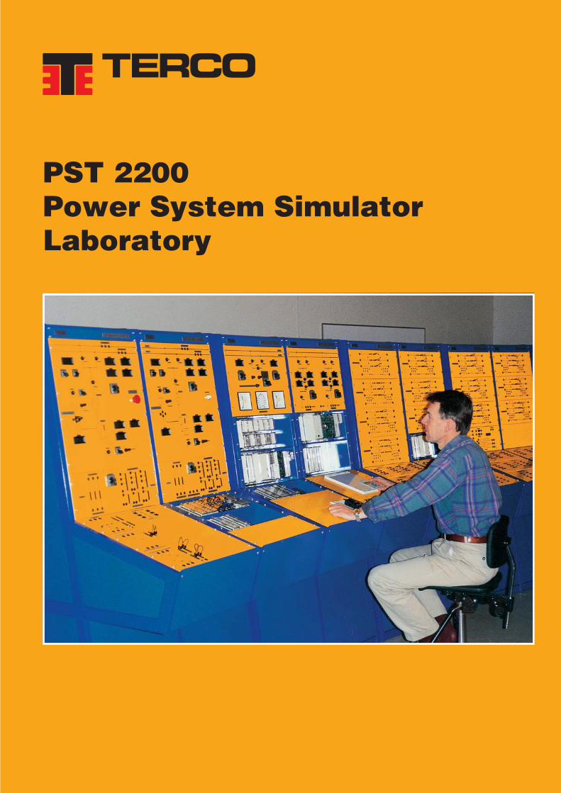
PST 2200 Power System Simulator Laboratory
Power System Simulator PST 2200
PST 2200Power System SimulatorLaboratory

Power System Simulator PST 2200

Power System Simulator PST 2200
1
CONTENTS
Introduction 2
General Information of the Power System Simulator PST 2200 3
Power Plant Module, PST 2210 5
Transmission Line & Distribution Module, PST 2220 7
Receiving Substation Module, PST 2230 8
Load Module, PST 2240 9
Measuring Details 10
Different set-ups of the Power System Simulator 11
SCADA system 12
List of Typical Experiments 12
Technical Information 13
Protective Relays 14
How to order 15
Power System Simulator, PSS 1200 16
Power System Simulator PST 2200
2
INTRODUCTION
Various kinds of simulation are used more often as an important aid to educate operatingand servicing personnel. With a simulator you can train people to make sensible decisionsand to act quickly and decisively under varying operating conditions. Moreover, you candemonstrate efforts which previously have been covered in theory only.
The Terco Power System Simulator has been designed for practical training of power engineers and techniciansin realistic conditions, close to life situations in genuine environment.A variety of training schemes programmed for:• power management staff• operators of power plants and substations• maintenance personnel• teaching of students• research in universitiescan be realised.
The Terco Power System Simulator has been developed in close co-operation with ABB of Sweden – one of the leadingsuppliers of power facilities world-wide – and Swedish State Power Board.
The result is, that a real power system has been copied for educational purposes.All the Protective Relays (Static and Numerical) are supplied by ABB and are exactly the same as used in realpower installations.
Our comprehensive manuals have been both written and tested together with the engineers from Swedish StatePower Board, to reflect realistic conditions of operation as well as emergency situations, which may occur, anddo occur, in every-day life of a power engineer or technician.
What is the main difference between TERCO Power System Simulator and an industrial power system?Apart from scaled down size, and much lower cost, the main difference consists of three major points:
• The TERCO Power Simulator is prepared to stand human errors, performed by the studentsduring the training.
• The TERCO Power Simulator includes facilities to produce simulated typical faults,in order to drill the students in resolute and correct reactions.
• The TERCO Power Simulator enables the students to survey both functions and malfunctionsin a complete power system, from generation to utilisation.
The TERCO Simulator is successfully used for training and education in universities and power companiesin 15 different countries throughout the world. The rich experience and know-how earned by us and our costumersis now at your disposal.
The Equipment
A Terco Standard Simulator is based on four modules:
• PST 2210 Power Plant Module• PST 2220 Transmission Line & Distribution Module• PST 2230 Receiving Substation Module• PST 2240 Load Module
The modules can be bought and operated individually and completed later with remaining modules.The standard solution is equipped with high technology state of the art protective relays from ABB.
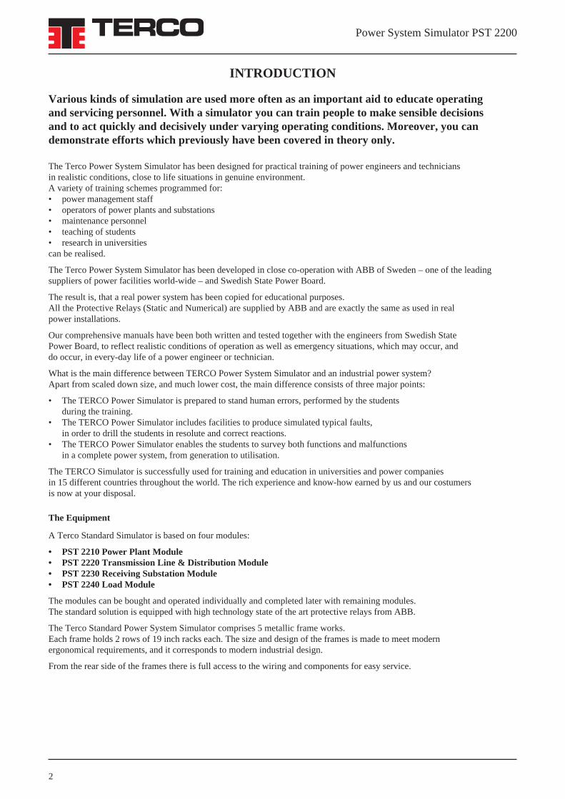
The Terco Standard Power System Simulator comprises 5 metallic frame works.Each frame holds 2 rows of 19 inch racks each. The size and design of the frames is made to meet modernergonomical requirements, and it corresponds to modern industrial design.
From the rear side of the frames there is full access to the wiring and components for easy service.
Power System Simulator PST 2200
3
The picture above shows a 7 frame option with two complete and fully equipped turbine-generator sections, additionaltransmission lines, an extended receiving substation and a standard load module.
General lay-out of the standard Power System Simulator
TERCO POWER SYSTEM SIMULATOR
Standard configuration.
GENERAL INFORMATION

Power System Simulator PST 2200
STANDARD CONFIGURATION
Module no. 1 PST 2210POWER PLANT MODULE WITH HIGH VOLTAGE BUSBARS AND OUTGOING LINES.
Switchboard for the Power Plant Simulator including turbine + synchronous generator, rectifiers, instruments,synchronising- and phasing devices, step-up transformer, current- and voltage transformers, protective relays, indications.A-B-busbars, two outgoing lines (including protective relays, instruments and corresponding switchboard).Two or more turbine-generator sections can be delivered as option.
Module no. 2 PST 2220TRANSMISSION LINES & DISTRIBUTION MODULE
Seven different artificial 3-phase transmission lines with possibilities to change and combine impedance elements byjumper positioning to constitute other OH HV-levels as well as cable models for distribution.All models have coils, capacitors and resistors designed to withstand overload and surges for dynamic as well asstatic experiments.
Module no. 3 PST 2230RECEIVING SUBSTATION MODULE WITH HIGH VOLTAGE SIDE
Receiving substation with one incoming line and two outgoing lines including a complete switchboard with instrumentsand corresponding protective relays. One step-down transformer including protective relays together with the correspondingtransformer. Two or more incoming lines, and three or more outgoing lines can be delivered as option.
Module no. 4 PST 2240LOAD MODULE
Load unit with single-phase and three-phase combinations of resistive, inductive and capacitive loads to simulateindustrial as well as domestic loads of symmetrical as well as non-symmetrical types. An induction motor with aflywheel is also included.
GENERAL
Necessary switches, instruments, and over-load protections are included.On each module current- and voltage transformers as well as protective relay blocks are connected mainly by jumpers.Protective relays etc. may be tested also together with external equipment.
On the transmission lines module, the impedance elements can be connected in different ways to design other maincharacteristics of other transmission links suitable to try different settings of the protections. This possibility of changingthe structure of the impedance map is very useful when programming the distance protection.
PROTECTION
Full generator and transformer protection is provided for the simulated power plant and system protection for theartificial lines, when ordering the standard simulator.
All protective relays are easily accessible from the control desk where settings can be done easily as well asindications and tripping connections. All protections can be tried individually without interfering with the in-operationsimulator because of the test blocks into which test handles can be put. (CT´s are automatically short circuited).All modules / function blocks in the protective relays can easily be disassembled from the front.All protective relays are of electronic type (Static and Numerical).
Any protective relay can be exchanged, combined or completed with other relays or relay functions because of theCOMBIFLEX connection system. A micro-processor-operated 1 + 3 zone distance protection relay can be installedas option on one of the outgoing HV-lines of the HV-substation.
The distance protection can be programmed for different HV-levels and characteristics and operates for three-phaseshort circuits, fault R-S, S-T, T-R, R-earth, S-earth, T-earth and with underimpedance start. There are separate timesettings for zone 2, 3 and 4. Each or all zones can be programmed for sensing in forward or reverse direction.
EXPERIMENTS
Experiments may be performed on the complete set-up of modules, on any of the four main modules individuallyor on protective relays individually by using an external relay tester e.g. MV 1427 (optional).
The protective relays may also be tested in combination with individually chosen line models and loads to provideexperiment groups not to interfere with other experiments on protective relays on the remaining main modules.
Most protective relays are operated from individual set-ups of voltage- and current transformers included with terminalsaccessible from the control pulpit.
4
Power System Simulator PST 2200
All windings are accessable externally to admit experimentson the transformer alone.
The step-up main transformer is supplying a double-bus sys-tem to the outgoing HV-substation.
The transformer can be given a rating of 50% or 100% byexternal resistive / inductive impedance elements, which areconnected by a contactor relay operation from the controldesk. Tappings on the secondary side of the transformer willmake it possible to change the voltage +/- 5 %.
The transformer has its windings accessible externally tomake it possible to perform tests like no-load test and short-circuit test.Primary as well as secondary voltages and currents can beread on instruments.
Electronic Relay Protections:
The Electronic Relay Protections for turbine / generator /step-up transformer comprises as a standard the followingfacilities:
• Differential protection for the generator• All-over differential relay for generator-transformer• Three-phase overcurrent relay for the generator
• Over voltage relay• Rotor Earth-fault relay of injection type• 95% Stator Earth-fault relay
5
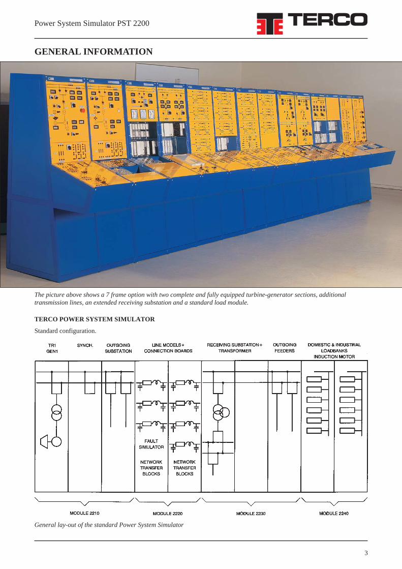
PST 2210, The Power Plant Simulator above is an extended version with two turbine-generator sections, fully equipped withall protective relays and step-up transformers. The standard version has one fully equipped turbine-generator section.
Module no. 1 PST 2210 POWER PLANT MODULE
The power generation is represented by a three-phase 1.2 kVA synchronous generator driven by a separately excitated2.0 kW DC motor as turbine.
As option, the turbine / generator can be manually set for different kW / Hz characteristics and for different start- andstop ramps.
The operation mode of the turbine / generator can be chosen between manual- or automatic control regarding power(frequency) and reactive power (voltage).
Digital instruments:
Armature (stator) currentArmature voltageField currentRevolutions per minuteReactive powerActive powerRotor current for turbine / DC-motor
Generator:
The reactance is referred to the nominal values of thegenerator U and I.The generator can be chosen either of the nominal power1.2 kVA or 2.0 kVA as optional.Both types are designed to be given parameters to simulatethe real size generators.The smaller type (specified above) is designed with cylindri-cal rotor and the bigger one, as an option, with salient poles.
The field controller is a static rectifier, which settings can beoptimised by the student.It can be used for automatic or manual control.
Transformer:
A 2 kVA transformer is used as a step-up transformer. Theratio is 1:√3. It is wound to withstand voltage surges withoutsaturation (and thus tripping the differential protection).External impedance elements may be added as an option tosimulate different sizes / impedances of the transformer.

Power System Simulator PST 2200
6
Synchronising panel of the Power Plant Module.
Turbine Generator Set: The power is generated by a 3-ph synchronous generator driven by a separately excitated DC-motoras turbine. The electrical machines set is electrically fully connected and mechanically mounted on a machine bed.
HV BusbarsThe HV busbars comprise an A-B system with inter-connections for load transfer.
All breaker functions are operated by contactor relays.The busbars are equipped with the following instruments:
• Digital volt- and ammeters for all phases• Synchronising instruments including synchronoscope• Voltage selector switches.
HV Outgoing Substation
The HV outgoing substation comprises two outgoing lineswhich can be connected to a radial network or a grid network(depending on the connections of the transmission linemodule).
The HV outgoing substation is equipped with the followinginstruments:• Digital volt-, ampere- and power meters for both lines• Voltage selector switchesAll switches / breakers are operated by contactor relays.
Electronic Relay Protectionsfor HV outgoing substation
The Electronic Relay Protections for HV outgoing substationare constituted by:• One three-phase over current relay with directional earth
fault protection for Line 1• One three-phase over current relay with directional earth
fault protection for Line 2.
As options are available:• Static 3+1 zone distance protective relay• Static impedance protective relay.
All protections are available for connecting by 4 mmoutlets via a test handle. All necessary current transformersand voltage transformers are included and the connectionsavailable from the desk.
The control elements fitted are mostly of the same industrialtype as those used in control rooms of power plants andsubstations.Circuit breakers are push-button operated with lamp indica-tions for the breaker status. Isolators are manually operatedand the physical position indicating open or closed position.
Optional protection:• Reverse power relay for the generator• Negative-sequence protection relay• Thermal overload relay for the generator
All protections are available for connectingby 4 mm outlets via a testhandle.
All necessary current transformers are includedand the terminals are available from the desk.
Power System Simulator PST 2200
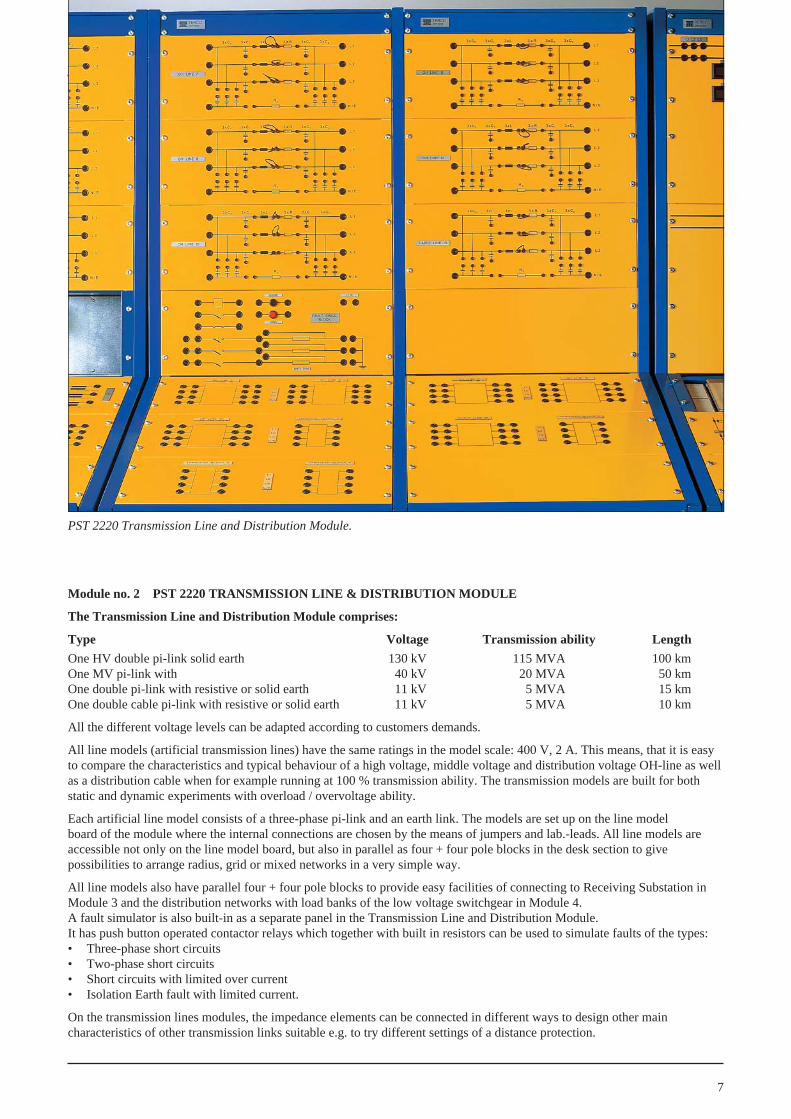
PST 2220 Transmission Line and Distribution Module.
Module no. 2 PST 2220 TRANSMISSION LINE & DISTRIBUTION MODULE
The Transmission Line and Distribution Module comprises:
Type Voltage Transmission ability Length
One HV double pi-link solid earth 130 kV 115 MVA 100 kmOne MV pi-link with 140 kV 120 MVA 150 kmOne double pi-link with resistive or solid earth 111 kV 115 MVA 115 kmOne double cable pi-link with resistive or solid earth 111 kV 115 MVA 110 km
All the different voltage levels can be adapted according to customers demands.
All line models (artificial transmission lines) have the same ratings in the model scale: 400 V, 2 A. This means, that it is easyto compare the characteristics and typical behaviour of a high voltage, middle voltage and distribution voltage OH-line as wellas a distribution cable when for example running at 100 % transmission ability. The transmission models are built for bothstatic and dynamic experiments with overload / overvoltage ability.
Each artificial line model consists of a three-phase pi-link and an earth link. The models are set up on the line modelboard of the module where the internal connections are chosen by the means of jumpers and lab.-leads. All line models areaccessible not only on the line model board, but also in parallel as four + four pole blocks in the desk section to givepossibilities to arrange radius, grid or mixed networks in a very simple way.
All line models also have parallel four + four pole blocks to provide easy facilities of connecting to Receiving Substation inModule 3 and the distribution networks with load banks of the low voltage switchgear in Module 4.A fault simulator is also built-in as a separate panel in the Transmission Line and Distribution Module.It has push button operated contactor relays which together with built in resistors can be used to simulate faults of the types:• Three-phase short circuits• Two-phase short circuits• Short circuits with limited over current• Isolation Earth fault with limited current.
On the transmission lines modules, the impedance elements can be connected in different ways to design other maincharacteristics of other transmission links suitable e.g. to try different settings of a distance protection.
7

Power System Simulator PST 2200
8
PST 2230 Receiving Substation Module: This picture is an optional version of two incoming lines, HV-busbars, step downtransformers (as incoming standard it is one of each), middle voltage busbar and two outgoing lines.
Module no. 3 PST 2230 RECEIVING SUBSTATION MODULE
The receiving substation comprises one incoming line, HV-busbars, transformer, middle voltage busbars, and two outgoinglines. Other combinations are optional.
Digital instruments:Voltage, current and power meters for incoming powerVoltage between busbars of incoming powerVoltage selector switches for incoming lineVoltage, current and power meters for outgoing powerVoltage between busbars of outgoing powerVoltage selector switches for outgoing lines
Electronic Relay Protections:• Busbar overcurrent protection• Transformer differential protection• HV / MV overcurrent protection• Neutral point voltage earth fault protection• Overcurrent (three-phase) and directional earth fault protection for outgoing Line 1• Overcurrent (three-phase) and directional earth fault protection for outgoing Line 2
• Multifunction motor protection relay for outgoing Line 2 (optional)• Auto-reclosing relay in combination with the protection for outgoing Line 1 (optional).
All protections are available by 4 mm outlets via a test handle. All current- and voltage transformers are includedand most terminals are available from the desk.
The step down transformer can be operated individually and all the terminals are available from the desk. All breakersare operated by contactor relays.
Possible earthing methods are: a) solid or resistive earth b) insulated earth c) Petersen coil

Power System Simulator PST 2200
PST 2240 Load Module.The picture shows an option with two motor protections.
Module no. 4PST 2240 LOAD MODULE
Low Voltage Distribution
The Low Voltage Distribution is constitutedby a busbar to which the substation can beconnected by the outgoing lines or by one ormore transmission models.
From the busbar there are 6 outgoing groups towhich loads can be connected. Each outgoinggroup is equipped with manually operatedswitches or selector switches.
All distribution groups are available by 4 mmsafety outlets to which loads can be connectedwith or without external instruments.
Instruments as optional:• Voltage and frequency on incoming busbars• Voltage selector switch• Ammeter on each outgoing group• kWh-meter
Load Group
The load module consists of groups of single phase and three-phase industrial and domestic loads.
The loads are of resistive, capacitive, inductive and active (motor) types: Three 3-phase groups can be varied insmall steps which together with the other loads will cover load possibilities from 0–150 % of nominal power.
By jumpers and switches it is possible to create single phase loads as well as other non-symmetrical loads.
One motor with flywheel is enclosed to the load module. Several motors can be added as optionals to make itpossible to study the dynamics of the system as well as the mechanical load sharings between two or more machines.The motor together with the flywheel will constitute a suitable load for the microprocessor operated motor protection(optional) on the outgoing line of the middle-voltage substation.
The Load Module comprises:• 6 resistive 1-phase load groups connectable by switches• 6 capacitive 1-phase load groups connectable by switches• 6 inductive 1-phase load groups connectable by switches• 2 three-phase controllable resistive loadbanks• 2 three-phase controllable capacitive loadbanks• 2 three-phase controllable inductive loadbanks• 1 induction motor with flywheel and mechanical brake, 0,25 kW
One induction motor Dahlander with flywheel and mechanical brake, 0,25/0,12kW (optional).
Other optional machines may be mounted on a metal basement or can be delivered on an external machine bed.
9

Power System Simulator PST 2200
10
Circuits: A 6 Channel Measuring Module.
Picture showing some of the instruments.
Circuits: A 24 Channel Logical Blocking Unit.
Channel Measuring Unit
Each measuring module has six signalamplifiers, all of them galvanically isolatingthe power side from the signal side. Allchannels are easily adapted for measuringAC or DC or mixed quantities. Calculation ofpower and reactive power is performed bymultipliers and addition circuits. On theoutput terminals all signals are available asinstant values and as buffered mean valueswithin +/-10V. This will simplify futureupgrading of the simulator for computercontrol.
Digital Instruments
The simulator contains, depending on options,normally 60 instrument amplifiers of which8 are spares for upgrading.A typical group of instruments will consistof one wattmeter, one VAr – meter oneammeter and one voltmeter which by meansof a selector switch can be connected formeasuring line to line voltages or line toneutral voltages.
Logic Blocking Unit
The logical blocking unit uses a micro-processor to determine whether an isolator canbe operated or not. All isolators and circuitbreakers in the simulator are assigned to aform where the user gives the conditions foroperation or not. The corresponding contactorrelays give status to the microprocessor whichin less than a msec compares all conditionswith the demand of the user turning the switchon the front. When upgrading the simulatorwith more circuit breakers and isolators, theuser simply has to reprogramme the micro-processor to fit the new constellation.
MEASURING DETAILS
Power System Simulator PST 2200
11
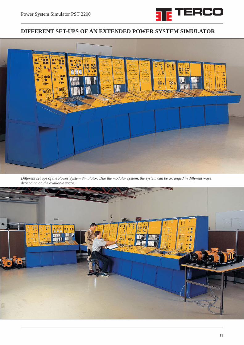
Different set ups of the Power System Simulator. Due the modular system, the system can be arranged in different waysdepending on the available space.
DIFFERENT SET-UPS OF AN EXTENDED POWER SYSTEM SIMULATOR
Power System Simulator PST 2200
SCADA System for Power System Simulator
Terco SCADA system (Supervisory Control and Data Aquisition) is a computerized supervisory, control and display systemto be used with Terco Power System Simulators (PSS and PST program).It will display all main instruments either as readouts or as graphs. All breakers and isolators belonging to the simulated powersystem can be operated from the PC.Operational status of the simulator is followed on a one-line diagram on the monitor, where the status of each breaker andeach isolator is indicated together with all instrument readouts.
Please ask for our separate SCADA leaflet.
List of Some Typical Experiments
Under normal conditions
• Settings of field control parameters, settings of turbine control rectifier parameters, settings of start- and stop ramps(=intake gate opening and closing)
• Checking AC-supply, DC supply, alarm indications, acknowledge- and cancel procedures, status indications of isolatorsand breakers. Start order.
• All performance diagrams of the generator can be studied.• Vector group of system transformer is checked.• Differential relays can be tested by resistive faults or trim faults caused inside the protective zones.
• Load distribution can be varied using auxiliary transformers to keep the currents within certain limits.This can also be studied by use of parallel lines where the line parameters are different.(Arranged for example by jumper connectors in the transmission module).
• Generator performance under steady state and dynamic conditions can be studied for different types of loads.
• Difference between manual and automatic control of voltage = reactive power control.• Difference between manual and automatic control of speed = active power control.• Rapidity of field control v.s. stability. Optimizing gain and time constants of voltage and current controllers.• Feedback systems.
• Voltage differences, frequency differences, phase difference, timing, instruments, blockings (synchronising).
• The dynamic characteristics of the controller can be examined.
• All protective relays can be tried individually with or without load with a relay testing unit of injection type (optional)where tripping levels are checked together with operating characteristics in the complex RX-plane as well as pick-upand tripping times by a built-in six digit timer.
• Characteristics of overcurrent and underimpedance starting elements can be obtained by means of loads and system feedprovided underimpedance protection is included..
• The tripping characteristics of a modified impedance relay can be determined by experiment (optional choice).• Impedance maps can be calculated easily to give information for an optimised selectivity plan of protection.
• By means of a ring main feed from one end various methods of protection can be studied, e.g. employing directionalovercurrent relays or non-directional relays with instantaneous opening of the main grid.
Under fault conditions:
• The reactances and time constant of the synchronous generator are of decisive importance for its transient behaviour.This can easily be studied in several ways. Also symmetrical and asymmetrical faults can be studied.
• Different types of system earthing methods can be studied: isolated, high resistance, low resistance and Petersen coil.
• Connecting the infinite busbar system in different parts of the network. Influence on fault currents and short circuitcurrents.
• Influence on fault currents and short circuit currents and relay protections. Settings of relays. Selectivity.
• Transient behaviour of generator can be shown when it is not correctly synchronised with the system.
• Single-phase and three-phase fault interruptions can be demonstrated for different lengths of transmission lines anddifferent values of power transmitted.
• The generator protection scheme is checked under conditions of deliberate maloperation of the generator and especiallyintroduced faults.
12

Power System Simulator PST 2200
• Overcurrent and under-voltage relays for motor protection operating in conjunction with the system relays can also beshown.
• Signalling, indications warnings, trippings, actions in the fault announciator system.
The list of experiments can be made much longer but these are a selection of experiments.
Regarding Protective Relays
• Connecting current and voltage transformers in different single- and three-phase configurations.
• Overcurrent protection• Overcurrent protection with time lag overcurrent relays• Over- and under voltage relays• Neutral point protection• Independent time characteristics• Directional overcurrent protection• Earth fault protection• Directional earth fault protection• Differential protections• Design principles• Instantaneous measuring relay• Influences of the DC-component• Directional relay for power• Signal relays + Auxiliary relays
• A typical feeder protection.
• Microprocessor operated 1 + 3 zones distance protection, programmable for low / high impedance isolated / impedanceearthing, under impedance tripping, phase-phase, earth fault etc (optional).
• Auto-reclosing, high speed or time delayed, 1 or several shots, memory functions, counter etc (optional).
13
Generator data:
Voltage 3 x 230 VNominal current 3,5 AFrequency 50 Hz/60HzSpeed 1500 rpm / 1800 rpmSynchronous reactance 97 %Transient reactance 17 %Subtransient reactance 8 %
The turbine / generator / step-up transformer:
• DC-machine 2.0 kW, simulating turbine
• 4-pole synchronous generator, 1.2 kVA, cos phi 0,8
• Static rectifier for speed control
• Static rectifier for voltage / VAr control
• Step-up transformer 230 / 400 V, 2.0 kVA
StandardsAll units, included in the Terco Power System Simulator,correspond, in all significant points, to IEC recommenda-tions.
Technical information:Power input : 3-phase 400 / 230 V, 50 & 60 Hz
Transmission LineTransmission
Type Voltage Aibility Length
HV double pi-link solid earth 130 kV 115 MVA 100 km
MV pi-link 140 kV 120 MVA 150 km
Double pi-link withresistive or solid earth 111 kV 115 MVA 115 km
Double cable pi-link with
resistive or solid earth 111 kV 115 MVA 110 km
Single-phased Load groupsResistive 6x200 WCapacitive 6x200 VArInductive 6x200 VAr
3-phase Loadbanks controllable in 6 stepsResistive 2x3-ph 0–900 WCapacitive 2x3-ph 0–900 VArInductive 2x3-ph 0–900 VAr
• 1 induction motor with flywheel and mechanicalbrake 0,25 kW
Optional• 1 induction motor Dahlander with flywheel and
mechanical brake 0,25/0,12 kW

Power System Simulator PST 2200
14
Level 2
POWER PLANT MODULE PST 2210-2Turbine / Generator / Step-up Transformer:
• All-over Differential Protection• Three-phase O/C Protection
Power Plant Substation outgoing HV-lines:
• Three-phase O/C and Directional Earth FaultProtection, Line 1
• Three-phase O/C and Directional Earth FaultProtection, Line 2
RECEIVING SUBSTATION MODULE PST 2230-2
• Busbar Overcurrent Protection• Transformer Differential Protection• Three-phase O/C and Directional Earth Fault
Protection, Line 1• Three-phase O/C and Directional Earth Fault
Protection, Line 2
STATIC PROTECTIVE RELAYS
Level 3 (standard)
POWER PLANT MODULE PST 2210-3Turbine / Generator / Step-up Transformer:
• Differential Generator Protection• All-over Differential Protection• Three-phase O/C Protection• Over Voltage Protection• Rotor Earth Fault Protection• 95 % Stator Earth Fault Protection
Power Plant Substation outgoing HV-lines:
• Three-phase O/C and Directional Earth FaultProtection, Line 1
• Three-phase O/C and Directional Earth FaultProtection, Line 2
RECEIVING SUBSTATION MODULE PST 2230-3
• Busbar Overcurrent Protection• Transformer Differential Protection• HV / MV Overcurrent Protection• Neutral Point Earth Fault Protection• Three-phase O/C and Directional Earth Fault
Protection, Line 1• Three-phase O/C and Directional Earth Fault
Protection, Line 2
Customer adapted protections
At customers request more sophisticated protectionscan be chosen in addition to e.g. level 3.
POWER PLANT MODULETurbine / Generator / Step-up Transformer:
• Reverse Power Relay for the Generator• Negative-sequence Protection Relay• Thermal Overload Relay for the Generator• Busbar Overcurrent Protection
Power Plant Substation outgoing HV-lines:
• 3 + 1 Zone Distance Protection• Impedance Relay
RECEIVING SUBSTATION MODULE
• Auto Reclosing Relay• Distance Protection for Incoming Line• Busbar Overcurrent Protection• Multifunction Motor Protection
Picture showing some of the Static Protective Relays in thePower Plant Module.

Power System Simulator PST 2200
How to order:
Power Plant Module Transmission Line Receiving Substation Module Load Module& Distribution Module
PST 2210-1 PST 2220 PST 2230-1 PST 2240PST 2210-2 PST 2230-2PST 2210-3 PST 2230-3
Level 1. Without static relay protections (normal protection by fusing included).
Level 2. A minimum level when the simulator has a choice of the most importanttypes of static protective relays built-in.
Level 3. Includes a standard set-up of static protective relays typical for small size real(standard) power plants and substations.
More sophisticated protections can be chosen as optional and adapted to customers request.
Of course, it is also possible to deliver Transmission Line Modules specially designed for the customers demand.The simulator may be upgraded from level to level and also in between.
Weights and Dimensions
Approx net weights 400 kg 275 kg 310 kg 275 kg
Turn-Key Deliveryand After-Sales Back-Up
The complete Power System Simulator is supplied onturn-key basis, with supervision of installation,commissioning and on-site training to be performed byTerco engineers.
Further training in Sweden or on site can be arranged onrequest, subject to a separate agreement.
Individual item specified in this catalogue, can also bedelivered on request.
Guarantee & TermsThe GUARANTEE is valid 12 months from delivery.
The guarantee covers repair or exchange of defective parts,due faulty design or workmanship at our factory.
Detailed conditions of guarantee are specified in our Termsof Guarantee.
All overseas deliveries are effected in special, made-to-order wooden crates, extremely sturdy and damage-resistent.
Sets of spare parts for 2–3 years of normal operations areincluded in the moduls, whereever necessary. The regularafter-sales service is performed by the worldwide networkof Terco representatives, with the advice and support ofour engineers.
TERCO reserves the right to make changes in the design, modifications orimprovments of the products at any time without incurring any obligations.
15
Power System Simulator PST 2200
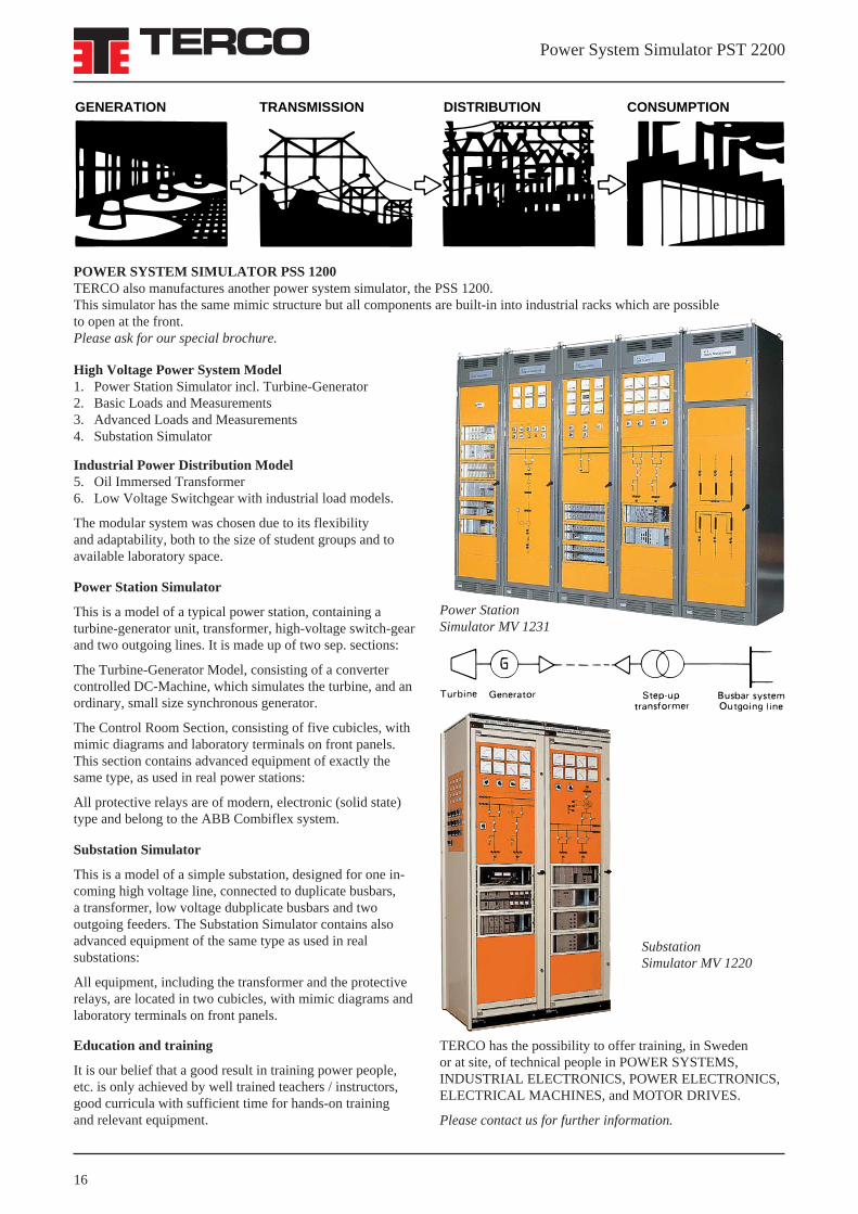
High Voltage Power System Model1. Power Station Simulator incl. Turbine-Generator2. Basic Loads and Measurements3. Advanced Loads and Measurements4. Substation Simulator
Industrial Power Distribution Model5. Oil Immersed Transformer6. Low Voltage Switchgear with industrial load models.
The modular system was chosen due to its flexibilityand adaptability, both to the size of student groups and toavailable laboratory space.
Power Station Simulator
This is a model of a typical power station, containing aturbine-generator unit, transformer, high-voltage switch-gearand two outgoing lines. It is made up of two sep. sections:
The Turbine-Generator Model, consisting of a convertercontrolled DC-Machine, which simulates the turbine, and anordinary, small size synchronous generator.
The Control Room Section, consisting of five cubicles, withmimic diagrams and laboratory terminals on front panels.This section contains advanced equipment of exactly thesame type, as used in real power stations:
All protective relays are of modern, electronic (solid state)type and belong to the ABB Combiflex system.
Substation Simulator
This is a model of a simple substation, designed for one in-coming high voltage line, connected to duplicate busbars,a transformer, low voltage dubplicate busbars and twooutgoing feeders. The Substation Simulator contains alsoadvanced equipment of the same type as used in realsubstations:
All equipment, including the transformer and the protectiverelays, are located in two cubicles, with mimic diagrams andlaboratory terminals on front panels.
Education and training
It is our belief that a good result in training power people,etc. is only achieved by well trained teachers / instructors,good curricula with sufficient time for hands-on trainingand relevant equipment.
POWER SYSTEM SIMULATOR PSS 1200TERCO also manufactures another power system simulator, the PSS 1200.This simulator has the same mimic structure but all components are built-in into industrial racks which are possibleto open at the front.Please ask for our special brochure.
TERCO has the possibility to offer training, in Swedenor at site, of technical people in POWER SYSTEMS,INDUSTRIAL ELECTRONICS, POWER ELECTRONICS,ELECTRICAL MACHINES, and MOTOR DRIVES.
Please contact us for further information.
Power StationSimulator MV 1231
SubstationSimulator MV 1220
16
GENERATION TRANSMISSION DISTRIBUTION CONSUMPTION

Power System Simulator PST 2200

Power System Simulator PST 2200
Terco Headoffice
POWER STATION SIMULATOR (PST) PROTECTION RELAYS
SCAN DRIVE
MATERIALTESTING
EL. INSTALL. &CONTACTORS
Terco headoffice and factory outside Stockholm, Sweden.
POWER STATION SIMULATOR (PSS)
CLASSICELECTRICALMACHINES1 kW
400 WSCAN LAB
ELECTRICALMACHINES
INDUSTRIALELECTRONICS
TERCO AB • P.O. Box 5014 • SE-14105 HUDDINGE – STOCKHOLM • SWEDENTelephone: +46 8 506 855 00 • Telefax: + 46 8 506 855 01 • www.terco.se • e-mail: [email protected]


![PST 2200 Power System Simulator Laboratory - Terco [Swedish] · The Terco Power System Simulator is a hardware simulator for hands-on training and has been designed for practical](https://static.documents.pub/doc/80x56/5f69313af254db32ff2d5af8/pst-2200-power-system-simulator-laboratory-terco-swedish-the-terco-power-system.jpg)


