24
60 10552 - 16/06/2011 PRODUCT LEAFLET PTI SUBSTATIONS Substations : Indoor and outdoor type PT BTM PTC PTM PTS 32
60 10552 - 16/06/2011
PRODUCT LEAFLET
PTI SUBSTATIONS
Substations : Indoor and outdoor type
PT BTM
PTC PTM
PTS 32
2
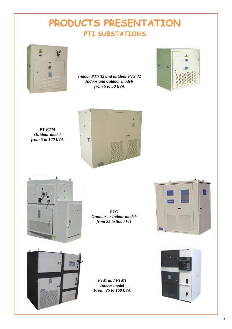
PRODUCTS PRESENTATION PTI SUBSTATIONS
Indoor PTS 32 and outdoor PTS 32
Indoor and outdoor models
from 5 to 50 kVA
PT BTM
Outdoor model
from 5 to 100 kVA
PTC
Outdoor or indoor models
from 25 to 500 kVA
PTM and PTMI
Indoor model
From 25 to 160 kVA
3
Pages
4 - 5
6 - 7
8 - 9
10 - 11
12 - 13
14 - 15
16 - 17
18 - 19
20 - 21 - 22
CONTENTS
GENERAL PRESENTATION…………………………. ....................................................................
SIMPLIFIED SUBSTATION PTS 32
* Indoor PTS 32…………………………………..........................................................
* Outdoor PTS 32..........................................................................................................
SIMPLIFIED SUBSTATION PT BTM ……………………………………………….………….
COMPACT SUBSTATION PTC
* Indoor PTC.................................................................................................................
* Outdoor PTC..............................................................................................................
MODULAR SUBSTATION PTM
* PTM............................................................................................................................
* PTM load break switch station...................................................................................
APPENDIX
* Substation’s walkway base ........................................................................................
PTI SUBSTATIONS From 5 to 500 kVA
4
These compact substations are modular units that ensure that the transformer substation operates smoothly:
they can be either step up or a step down models, for indoor or outdoor use.
They offer all the advantages of an integrated and modular design:
* Easy to set up, the station is ready to be connected.
* Station can be made up according to specific requirements
They also offer all the advantages of products made with quality mateials :
* Indoor models in steel or aluminium sheets.
* Outdoor models in painted aluminium sheet providing:
- Greater better resistance against corrosion
- Easier handling and installation due to its lightness.
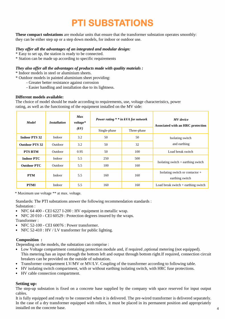
Different models available:
The choice of model should be made according to requirements, use, voltage characteristics, power
rating, as well as the functioning of the equipment installed on the MV side:
* Maximum use voltage ** at max. voltage.
Standards: The PTI substations answer the following recommendation standards :
Substation :
NFC 64 400 - CEI 6227 I-200 : HV equipment in metallic wrap.
NFC 20 010 - CEI 60529 : Protection degrees insured by the wraps.
Transformer :
NFC 52-100 - CEI 60076 : Power transformer.
NFC 52-410 : HV / LV transformer for public lighting.
Composition : Depending on the models, the substation can comprise :
Low Voltage compartment containing protection module and, if required ,optional metering (not equipped).
This metering has an input through the bottom left and output through bottom right.If required, connection circuit
breakers can be provided on the outside of substation.
Transformer compartment LV/MV or MV/LV. Coupling of the transformer according to following table.
HV isolating switch compartment, with or without earthing isolating switch, with HRC fuse protections.
HV cable connection compartment.
Setting up:
The step-up substation is fixed on a concrete base supplied by the company with space reserved for input output
cables.
It is fully equipped and ready to be connected when it is delivered. The pre-wired transformer is delivered separately.
In the case of a dry transformer equipped with rollers, it must be placed in its permanent position and appropriately
installed on the concrete base.
PTI SUBSTATIONS
Model Installation
Max
voltage*
(kV)
MV device
Associated with an HRC protection
Power rating * * in kVA for network
Single-phase Three-phase
Indoor PTS 32 Indoor 3.2 50 50 Isolating switch
and earthing Outdoor PTS 32 Outdoor 3.2 50 32
PTS BTM Outdoor 0.95 50 100 Load break switch
Indoor PTC Indoor 5.5 250 500 Isolating switch + earthing switch
Outdoor PTC Outdoor 5.5 100 160
PTM Indoor 5.5 160 160 Isolating switch or contactor +
earthing switch
PTMI Indoor 5.5 160 160 Load break switch + earthing switch
5
Type
Maximum LV BTM Medium voltage MV
Single Three Three-single Single Three Three-single
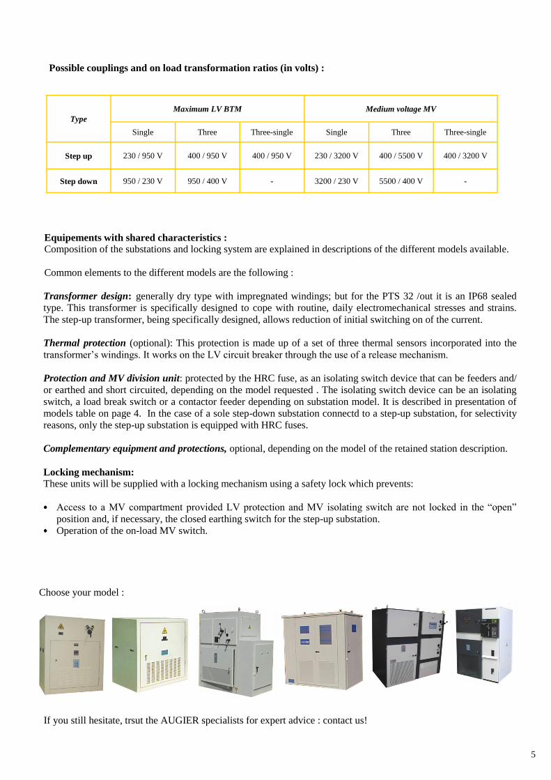
Step up 230 / 950 V 400 / 950 V 400 / 950 V 230 / 3200 V 400 / 5500 V 400 / 3200 V
Step down 950 / 230 V 950 / 400 V - 3200 / 230 V 5500 / 400 V -
Equipements with shared characteristics : Composition of the substations and locking system are explained in descriptions of the different models available.
Common elements to the different models are the following :
Transformer design: generally dry type with impregnated windings; but for the PTS 32 /out it is an IP68 sealed
type. This transformer is specifically designed to cope with routine, daily electromechanical stresses and strains.
The step-up transformer, being specifically designed, allows reduction of initial switching on of the current.
Thermal protection (optional): This protection is made up of a set of three thermal sensors incorporated into the
transformer’s windings. It works on the LV circuit breaker through the use of a release mechanism.
Protection and MV division unit: protected by the HRC fuse, as an isolating switch device that can be feeders and/
or earthed and short circuited, depending on the model requested . The isolating switch device can be an isolating
switch, a load break switch or a contactor feeder depending on substation model. It is described in presentation of
models table on page 4. In the case of a sole step-down substation connectd to a step-up substation, for selectivity
reasons, only the step-up substation is equipped with HRC fuses.
Complementary equipment and protections, optional, depending on the model of the retained station description.
Locking mechanism:
These units will be supplied with a locking mechanism using a safety lock which prevents:
Access to a MV compartment provided LV protection and MV isolating switch are not locked in the “open”
position and, if necessary, the closed earthing switch for the step-up substation.
Operation of the on-load MV switch.
If you still hesitate, trsut the AUGIER specialists for expert advice : contact us!
Choose your model :
Possible couplings and on load transformation ratios (in volts) :
6
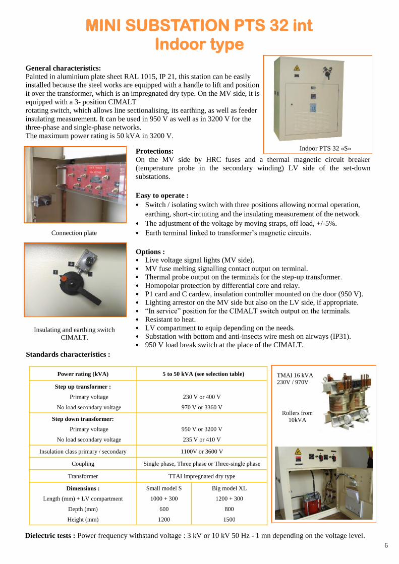
General characteristics: Painted in aluminium plate sheet RAL 1015, IP 21, this station can be easily
installed because the steel works are equipped with a handle to lift and position
it over the transformer, which is an impregnated dry type. On the MV side, it is
equipped with a 3- position CIMALT
rotating switch, which allows line sectionalising, its earthing, as well as feeder
insulating measurement. It can be used in 950 V as well as in 3200 V for the
three-phase and single-phase networks.
The maximum power rating is 50 kVA in 3200 V.
Protections:
On the MV side by HRC fuses and a thermal magnetic circuit breaker
(temperature probe in the secondary winding) LV side of the set-down
substations.
Easy to operate :
Switch / isolating switch with three positions allowing normal operation,
earthing, short-circuiting and the insulating measurement of the network.
The adjustment of the voltage by moving straps, off load, +/-5%.
Earth terminal linked to transformer’s magnetic circuits.
Options : Live voltage signal lights (MV side).
MV fuse melting signalling contact output on terminal.
Thermal probe output on the terminals for the step-up transformer.
Homopolar protection by differential core and relay.
P1 card and C cardew, insulation controller mounted on the door (950 V).
Lighting arrestor on the MV side but also on the LV side, if appropriate.
“In service” position for the CIMALT switch output on the terminals.
Resistant to heat.
LV compartment to equip depending on the needs.
Substation with bottom and anti-insects wire mesh on airways (IP31).
950 V load break switch at the place of the CIMALT.
Connection plate
Insulating and earthing switch
CIMALT.
Power rating (kVA) 5 to 50 kVA (see selection table)
Step up transformer :
Primary voltage
No load secondary voltage
230 V or 400 V
970 V or 3360 V
Step down transformer:
Primary voltage
No load secondary voltage
950 V or 3200 V
235 V or 410 V
Insulation class primary / secondary 1100V or 3600 V
Coupling Single phase, Three phase or Three-single phase
Transformer TTAI impregnated dry type
Dimensions :
Length (mm) + LV compartment
Depth (mm)
Height (mm)
Small model S
1000 + 300
600
1200
Big model XL
1200 + 300
800
1500
Dielectric tests : Power frequency withstand voltage : 3 kV or 10 kV 50 Hz - 1 mn depending on the voltage level.
Standards characteristics :
MINI SUBSTATION PTS 32 int Indoor type
Indoor PTS 32 «S»
Rollers from
10kVA
TMAI 16 kVA
230V / 970V
7
Voltage
5 7,5 10 16 25 32 50 Power rating
kVA
950 V Single phase S S S S S* XL* XL*
950 V Three phase - - - XL XL XL XL*
3200 V Single phase S S S S S XL XL
3200 V Three phase - - - XL XL XL XL
SELECTION TABLE - POWER RATING LIMITS OF USE
Power rating compatible to
the voltage level
S : small model
XL : big model
* With 950 V load break switch
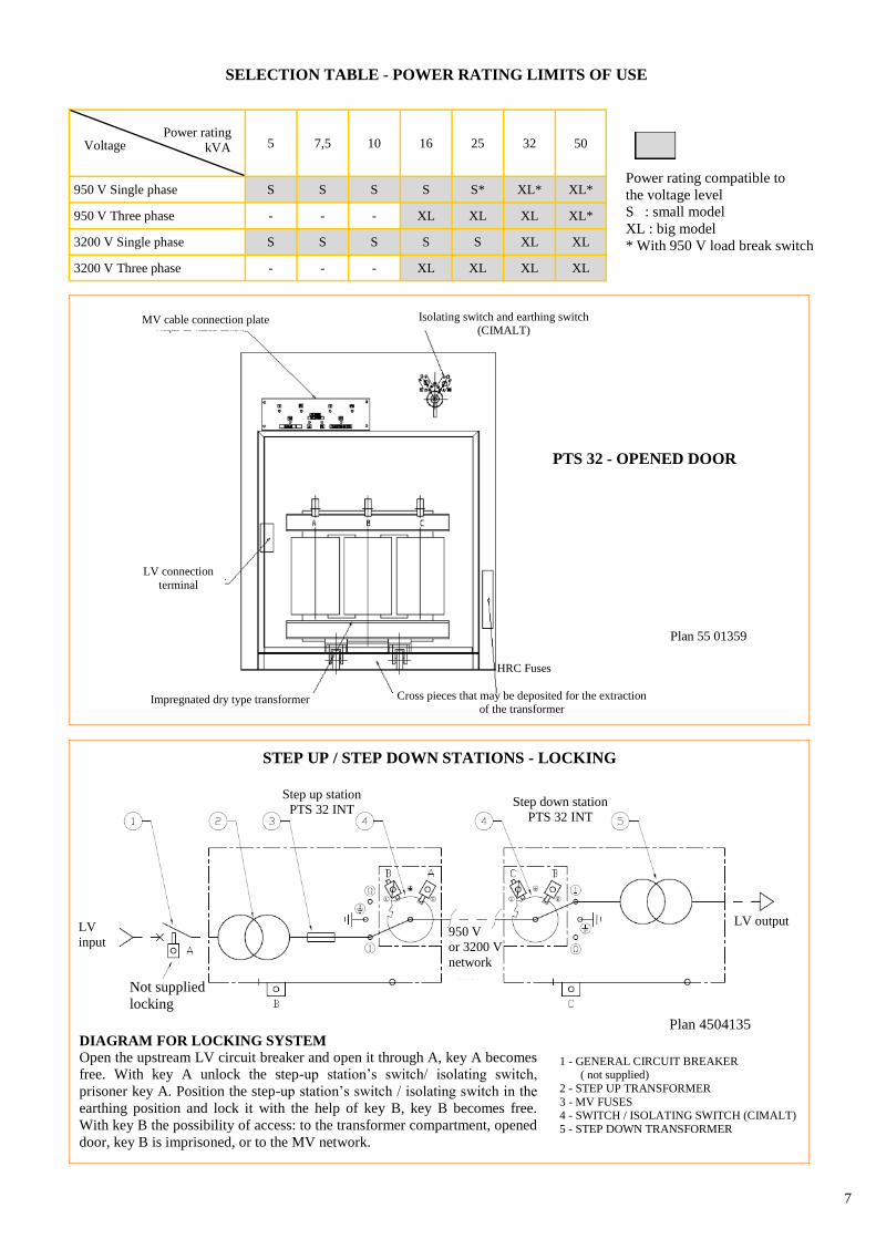
PTS 32 - OPENED DOOR
MV cable connection plate Isolating switch and earthing switch
(CIMALT)
Impregnated dry type transformer Cross pieces that may be deposited for the extraction of the transformer
HRC Fuses
Plan 55 01359
LV connection
terminal
DIAGRAM FOR LOCKING SYSTEM Open the upstream LV circuit breaker and open it through A, key A becomes
free. With key A unlock the step-up station’s switch/ isolating switch,
prisoner key A. Position the step-up station’s switch / isolating switch in the
earthing position and lock it with the help of key B, key B becomes free.
With key B the possibility of access: to the transformer compartment, opened
door, key B is imprisoned, or to the MV network.
1 - GENERAL CIRCUIT BREAKER ( not supplied)
2 - STEP UP TRANSFORMER
3 - MV FUSES 4 - SWITCH / ISOLATING SWITCH (CIMALT)
5 - STEP DOWN TRANSFORMER
STEP UP / STEP DOWN STATIONS - LOCKING
Plan 4504135
LV output
Step down station
PTS 32 INT
Step up station
PTS 32 INT
950 V
or 3200 V
network
LV
input
Not supplied
locking
8
Connection plate
Insulating and earthing switch CIMALT
Standard characteristics :
Power rating (kVA) 5 to 50 kVA (see selection table)
Step up transformer :
Primary voltage
No load secondary voltage
230 V or 400 V
970 V or 3360 V
Step down transformer :
Primary voltage
No load secondary voltage
950 V or 3200 V
235 V or 410 V
Primary / secondary insulating class 1100V or 3600 V
Coupling Single phase, three phase
Transformer IP 68 TSA or TED type
Dimensions :
Length (mm) + LV compartment
Width (mm)
Height (mm)
Small model S
1000 + 300
600
1200
Big model XL
1200 + 300
800
1500
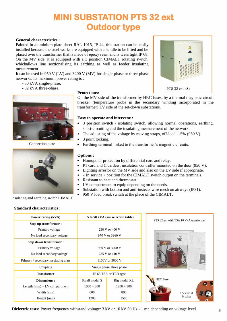
General characteristics : Painted in aluminium plate sheet RAL 1015, IP 44, this station can be easily
installed because the steel works are equipped with a handle to be lifted and be
placed over the transformer that is made of epoxy resin and is watertight IP 68.
On the MV side, it is equipped with a 3 position CIMALT rotating switch,
whichallows line sectionalising its earthing as well as feeder insulating
measurement.
It can be used in 950 V (LV) and 3200 V (MV) for single-phase or three-phase
networks. Its maximum power rating is :
- 50 kVA single-phase.
- 32 kVA three-phase. Protections:
On the MV side of the transformer by HRC fuses, by a thermal magnetic circuit
breaker (temperature probe in the secondary winding incorporated in the
transformer) LV side of the set-down substations.
Easy to operate and intervene :
3 position switch / isolating switch, allowing normal operations, earthing,
short-circuiting and the insulating measurement of the network.
The adjusting of the voltage by moving straps, off-load +-5% (950 V).
3 point locking.
Earthing terminal linked to the transformer’s magnetic circuits.
Options :
Homopolar protection by differential core and relay.
P1 card and C cardew, insulation controller mounted on the door (950 V).
Lighting arrestor on the MV side and also on the LV side if appropriate.
« In service » position for the CIMALT switch output on the terminals.
Resistant to heat and thermostat.
LV compartment to equip depending on the needs.
Substation with bottom and anti-instects wire mesh on airways (IP31).
950 V load break switch at the place of the CIMALT.
MINI SUBSTATION PTS 32 ext Outdoor type
PTS 32 ext «S»
Dielectric tests: Power frequency withstand voltage: 3 kV or 10 kV 50 Hz - 1 mn depending on voltage level.
PTS 32 ext with TSA 10 kVA transformer
HRC Fuse
LV circuit breaker
9
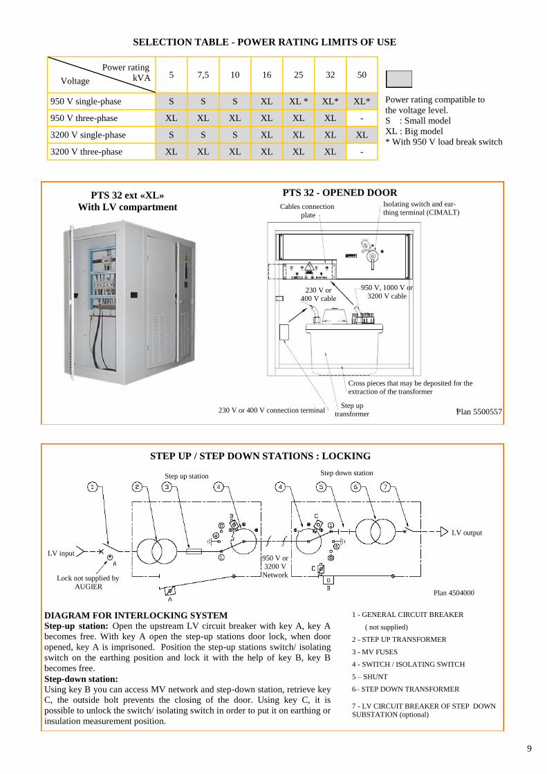
Voltage 5 7,5 10 16 25 32 50
Power rating
kVA
950 V single-phase S S S XL XL * XL* XL*
950 V three-phase XL XL XL XL XL XL -
3200 V single-phase S S S XL XL XL XL
3200 V three-phase XL XL XL XL XL XL -
Power rating compatible to
the voltage level.
S : Small model
XL : Big model
* With 950 V load break switch
SELECTION TABLE - POWER RATING LIMITS OF USE
PTS 32 ext «XL»
With LV compartment
PTS 32 - OPENED DOOR
Cables connection
plate
Isolating switch and ear-thing terminal (CIMALT)
950 V, 1000 V or
3200 V cable 230 V or
400 V cable
Step up transformer Plan 5500557 230 V or 400 V connection terminal
Cross pieces that may be deposited for the extraction of the transformer
DIAGRAM FOR INTERLOCKING SYSTEM
Step-up station: Open the upstream LV circuit breaker with key A, key A
becomes free. With key A open the step-up stations door lock, when door
opened, key A is imprisoned. Position the step-up stations switch/ isolating
switch on the earthing position and lock it with the help of key B, key B
becomes free.
Step-down station:
Using key B you can access MV network and step-down station, retrieve key
C, the outside bolt prevents the closing of the door. Using key C, it is
possible to unlock the switch/ isolating switch in order to put it on earthing or
insulation measurement position.
1 - GENERAL CIRCUIT BREAKER
( not supplied)
2 - STEP UP TRANSFORMER
3 - MV FUSES
4 - SWITCH / ISOLATING SWITCH
5 – SHUNT
6– STEP DOWN TRANSFORMER
7 - LV CIRCUIT BREAKER OF STEP DOWN SUBSTATION (optional)
STEP UP / STEP DOWN STATIONS : LOCKING
Plan 4504000
Step up station Step down station
LV output
LV input 950 V or 3200 V
Network Lock not supplied by AUGIER
10
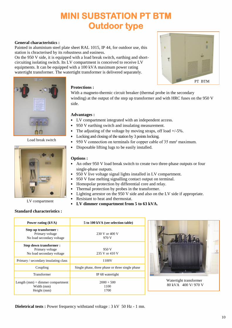
General characteristics : Painted in aluminium steel plate sheet RAL 1015, IP 44, for outdoor use, this
station is chracterised by its robustness and easiness.
On the 950 V side, it is equipped with a load break switch, earthing and short-
circuiting isolating switch. Its LV compartment is conceived to receive LV
equipments. It can be equipped with a 100 kVA maximum power rating
watertight transformer. The watertight transformer is delivered separately.
Load break switch
LV compartment
Protections :
With a magneto-thermic circuit breaker (thermal probe in the secondary
winding) at the output of the step up transformer and with HRC fuses on the 950 V
side.
Advantages :
LV compartment integrated with an independent access.
950 V earthing switch and insulating measurement.
The adjusting of the voltage by moving straps, off load +/-5%.
Locking and closing of the station by 3 points locking.
950 V connection on terminals for copper cable of 35 mm² maximum.
Disposable lifting lugs to be easily installed.
Options :
An other 950 V load break switch to create two three-phase outputs or four
single-phase outputs.
950 V live voltage signal lights installed in LV compartment.
950 V fuse melting signalling contact output on terminal.
Homopolar protection by differential core and relay.
Thermal protection by probes in the transformer.
Lighting arrestor on the 950 V side and also on the LV side if appropriate.
Resistant to heat and thermostat.
LV dimmer compartment from 5 to 63 kVA.
Dieletrical tests : Power frequency withstand voltage : 3 kV 50 Hz - 1 mn.
Power rating (kVA) 5 to 100 kVA (see selection table)
Step up transformer :
Primary voltage
No load secondary voltage
230 V or 400 V
970 V
Step down transformer :
Primary voltage
No load secondary voltage
950 V
235 V or 410 V
Primary / secondary insulating class 1100V
Coupling Single phase, three phase or three single phase
Transformer IP 68 watertight
Length (mm) + dimmer compartment
Width (mm)
Height (mm)
2000 + 500
1100
1700
Standard characteristics :
Watertight transformer
80 kVA 400 V/ 970 V
MINI SUBSTATION PT BTM Outdoor type
PT BTM
11
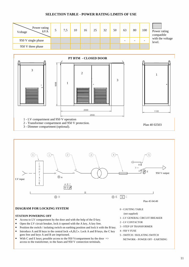
Voltage
Power rating
kVA 5 7,5 10 16 25 32 50 63 80 100
950 V single phase - - -
950 V three phase
SELECTION TABLE - POWER RATING LIMITS OF USE
Power rating
compatible
with the voltage
level.
1 - LV compartment and 950 V operation
2 - Transformer compartment and 950 V protection.
3 - Dimmer compartment (optional). Plan 40 02503
PT BTM - CLOSED DOOR
1
2 3
1
3
DIAGRAM FOR LOCKING SYSTEM
STATION POWERING OFF
Access to LV compartment by the door and with the help of the D key.
Open the LV circuit breaker, lock it opened with the A key, A key free.
Position the switch / isolating switch on earthing position and lock it with the B key.
Introduce A and B keys in the central lock «A,B,C». Lock A and B keys, the C key
goes free and keys A and B are imprisoned.
With C and E keys; possible access to the 950 Vcompartment by the door =>
access to the transformer, to the fuses and 950 V connection terminals.
0 - COUTING TABLE
(not supplied)
1 - LV GENERAL CIRCUIT BREAKER
2 - LV CONTACTOR
3 - STEP UP TRANSFORMER
4 - 950 V FUSE
5 - SWITCH / ISOLATING SWITCH
NETWORK - POWER OFF - EARTHING
Plan 45 04149
950 V output
LV input
12
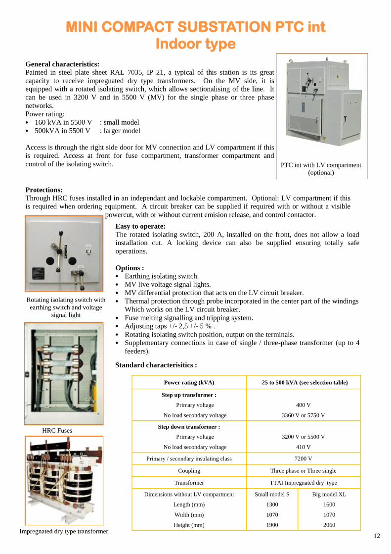
General characteristics:
Painted in steel plate sheet RAL 7035, IP 21, a typical of this station is its great
capacity to receive impregnated dry type transformers. On the MV side, it is
equipped with a rotated isolating switch, which allows sectionalising of the line. It
can be used in 3200 V and in 5500 V (MV) for the single phase or three phase
networks.
Power rating:
160 kVA in 5500 V : small model
500kVA in 5500 V : larger model
Access is through the right side door for MV connection and LV compartment if this
is required. Access at front for fuse compartment, transformer compartment and
control of the isolating switch.
Protections:
Through HRC fuses installed in an independant and lockable compartment. Optional: LV compartment if this
is required when ordering equipment. A circuit breaker can be supplied if required with or without a visible
powercut, with or without current emision release, and control contactor.
Rotating isolating switch with
earthing switch and voltage
signal light
Easy to operate: The rotated isolating switch, 200 A, installed on the front, does not allow a load
installation cut. A locking device can also be supplied ensuring totally safe
operations.
Options : Earthing isolating switch.
MV live voltage signal lights.
MV differential protection that acts on the LV circuit breaker.
Thermal protection through probe incorporated in the center part of the windings
Which works on the LV circuit breaker.
Fuse melting signalling and tripping system.
Adjusting taps +/- 2,5 +/- 5 % .
Rotating isolating switch position, output on the terminals.
Supplementary connections in case of single / three-phase transformer (up to 4
feeders).
HRC Fuses
Impregnated dry type transformer
Power rating (kVA) 25 to 500 kVA (see selection table)
Step up transformer :
Primary voltage
No load secondary voltage
400 V
3360 V or 5750 V
Step down transformer :
Primary voltage
No load secondary voltage
3200 V or 5500 V
410 V
Primary / secondary insulating class 7200 V
Coupling Three phase or Three single
Transformer TTAI Impregnated dry type
Dimensions without LV compartment
Length (mm)
Width (mm)
Height (mm)
Small model S
1300
1070
1900
Big model XL
1600
1070
2060
Standard characterisitics :
MINI COMPACT SUBSTATION PTC int Indoor type
PTC int with LV compartment
(optional)
13
Coupling
Power rating
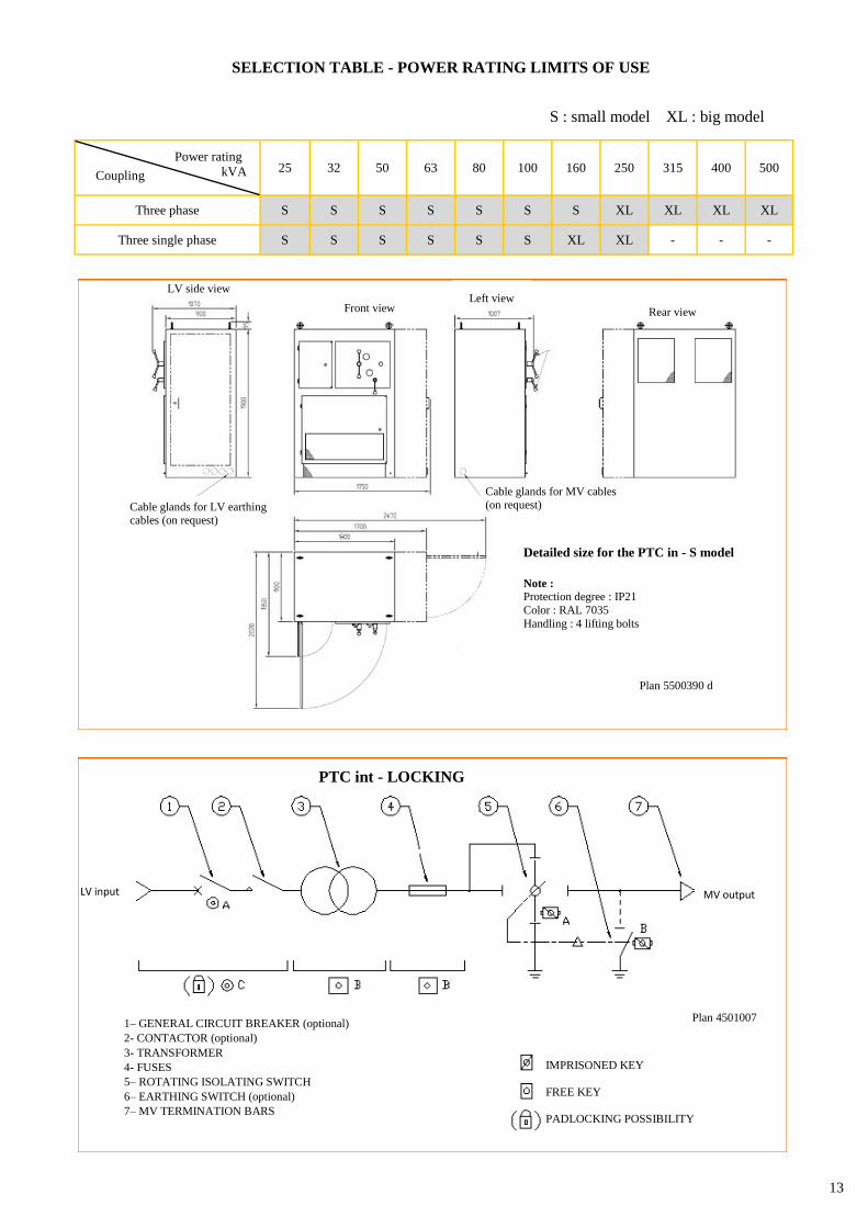
kVA 25 32 50 63 80 100 160 250 315 400 500
Three phase S S S S S S S XL XL XL XL
Three single phase S S S S S S XL XL - - -
SELECTION TABLE - POWER RATING LIMITS OF USE
S : small model XL : big model
1– GENERAL CIRCUIT BREAKER (optional)
2- CONTACTOR (optional)
3- TRANSFORMER
4- FUSES
5– ROTATING ISOLATING SWITCH
6– EARTHING SWITCH (optional)
7– MV TERMINATION BARS
IMPRISONED KEY
FREE KEY
PADLOCKING POSSIBILITY
LV input MV output
PTC int - LOCKING
Plan 4501007
Plan 5500390 d
LV side view
Front view
Cable glands for MV cables (on request)
Left view
Rear view
Cable glands for LV earthing cables (on request)
Detailed size for the PTC in - S model
Note :
Protection degree : IP21
Color : RAL 7035
Handling : 4 lifting bolts
14
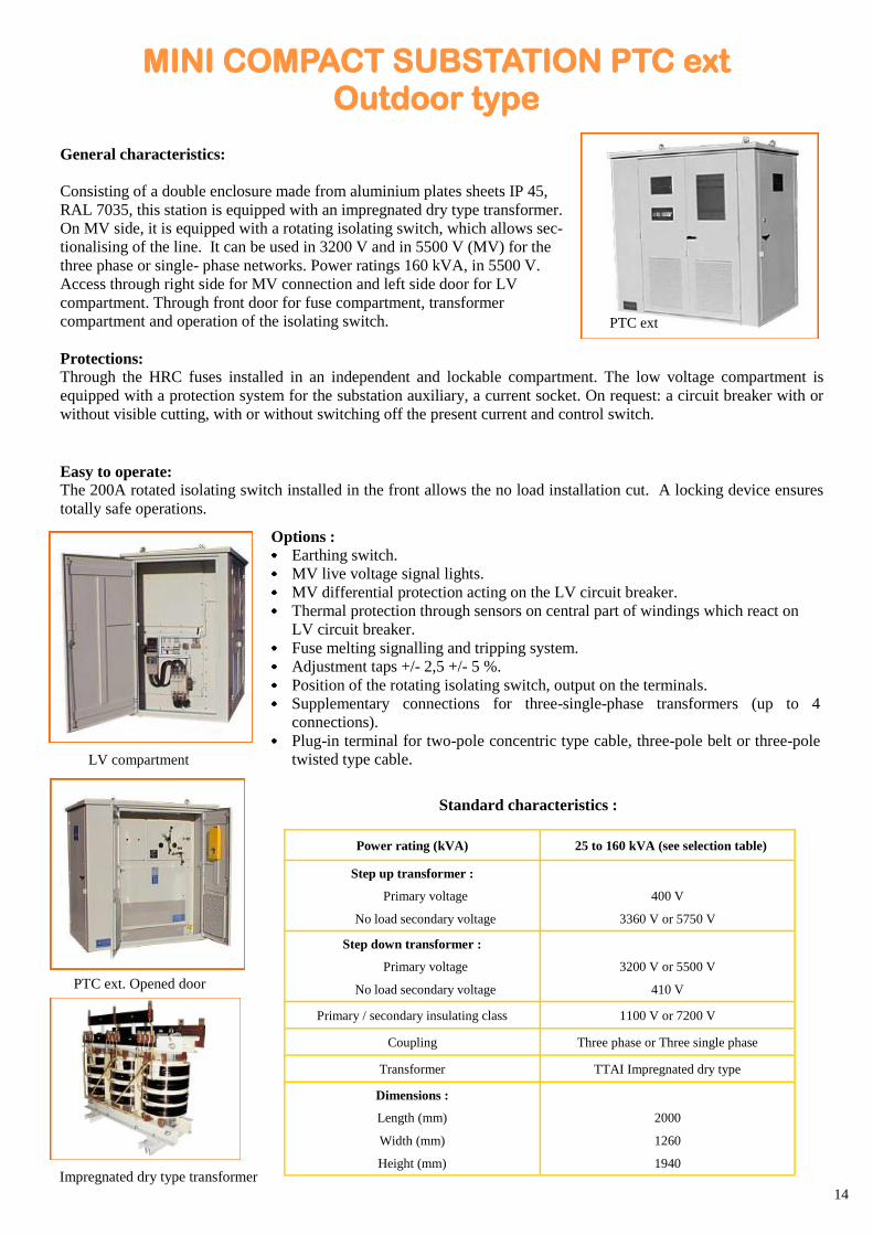
General characteristics:
Consisting of a double enclosure made from aluminium plates sheets IP 45,
RAL 7035, this station is equipped with an impregnated dry type transformer.
On MV side, it is equipped with a rotating isolating switch, which allows sec-
tionalising of the line. It can be used in 3200 V and in 5500 V (MV) for the
three phase or single- phase networks. Power ratings 160 kVA, in 5500 V.
Access through right side for MV connection and left side door for LV
compartment. Through front door for fuse compartment, transformer
compartment and operation of the isolating switch.
Protections:
Through the HRC fuses installed in an independent and lockable compartment. The low voltage compartment is
equipped with a protection system for the substation auxiliary, a current socket. On request: a circuit breaker with or
without visible cutting, with or without switching off the present current and control switch.
Easy to operate:
The 200A rotated isolating switch installed in the front allows the no load installation cut. A locking device ensures
totally safe operations.
Options : Earthing switch.
MV live voltage signal lights.
MV differential protection acting on the LV circuit breaker.
Thermal protection through sensors on central part of windings which react on
LV circuit breaker.
Fuse melting signalling and tripping system.
Adjustment taps +/- 2,5 +/- 5 %.
Position of the rotating isolating switch, output on the terminals.
Supplementary connections for three-single-phase transformers (up to 4
connections).
Plug-in terminal for two-pole concentric type cable, three-pole belt or three-pole
twisted type cable.
Power rating (kVA) 25 to 160 kVA (see selection table)
Step up transformer :
Primary voltage
No load secondary voltage
400 V
3360 V or 5750 V
Step down transformer :
Primary voltage
No load secondary voltage
3200 V or 5500 V
410 V
Primary / secondary insulating class 1100 V or 7200 V
Coupling Three phase or Three single phase
Transformer TTAI Impregnated dry type
Dimensions :
Length (mm)
Width (mm)
Height (mm)
2000
1260
1940
Standard characteristics :
Impregnated dry type transformer
PTC ext. Opened door
LV compartment
MINI COMPACT SUBSTATION PTC ext Outdoor type
PTC ext
15
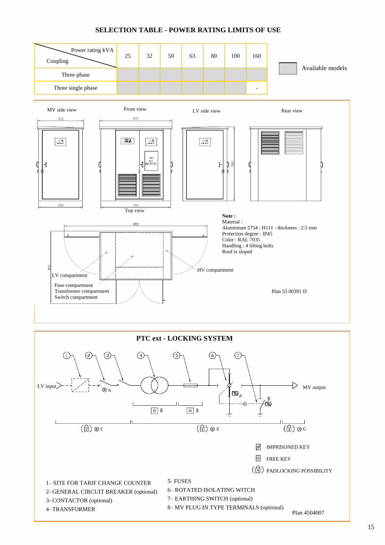
Coupling
Power rating kVA 25 32 50 63 80 100 160
Three phase
Three single phase -
Available models
SELECTION TABLE - POWER RATING LIMITS OF USE
Top view
Rear view MV side view Front view LV side view
Note :
Material :
Aluminium 5754 : H111 - thickness : 2.5 mm
Protection degree : IP45 Color : RAL 7035
Handling : 4 lifting bolts
Roof is sloped
HV compartment
LV compartment
Fuse compartment Transformer compartment
Switch compartment Plan 55 00391 D
1– SITE FOR TARIF CHANGE COUNTER
2- GENERAL CIRCUIT BREAKER (optional)
3- CONTACTOR (optional)
4- TRANSFORMER
5- FUSES
6– ROTATED ISOLATING WITCH
7– EARTHING SWITCH (optional)
8– MV PLUG IN TYPE TERMINALS (optional) Plan 4504007
PTC ext - LOCKING SYSTEM
MV output LV input
IMPRISONED KEY
FREE KEY
PADLOCKING POSSIBILITY
16
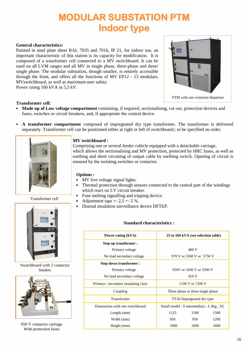
General characteristics:
Painted in steel plate sheet RAL 7035 and 7016, IP 21, for indoor use, an
important characteristic of this station is its capacity for modification. It is
composed of a transformer cell connected to a MV switchboard. It can be
used on all LVM ranges and all MV in single phase, three-phase and three/
single phase. The modular substation, though smaller, is entirely accessible
through the front, and offers all the functions of MV EP12 - 13 modulars,
MVswitchboard, as well as maximum user safety.
Power rating 160 kVA in 5,5 kV.
Transformer cell:
Made up of Low voltage compartment containing, if required, sectionalising, cut out, protection devices and
fuses, switches or circuit breakers, and, if appropriate the control device.
A transformer compartment composed of impregnated dry type transformer. The transformer is delivered
separately. Transformer cell can be positioned either at right or left of switchboard,: to be specified on order.
MV switchboard :
Comprising one or several feeder cubicle equipped with a detachable carriage,
which allows the sectionalising and MV protection, protected by HRC fuses, as well as
earthing and short circuiting of output cable by earthing switch. Opening of circuit is
ensured by the isolating switches or contactor.
Options : MV live voltage signal lights.
Thermal protection through sensors connected to the central part of the windings
which react on LV circuit breaker.
Fuse melting signalling and tripping device.
Adjustment taps +- 2,5 +- 5 %.
Diurnal insulation surveillance device DFTEP.
Standard characteristics :
Transformer cell
Switchboard with 2 contactor
feeders
950 V contactor carriage
With protection fuses
Power rating (kVA) 25 to 160 kVA (see selection table)
Step up transformer :
Primary voltage
No load secondary voltage
400 V
970 V or 3360 V or 5750 V
Step down transformer :
Primary voltage
No load secondary voltage
950V or 3200 V or 5500 V
410 V
Primary / secondary insulating class 1100 V or 7200 V
Coupling Three phase or three single phase
Transformer TTAI Impregnated dry type
Dimensions with one switchboard
Length (mm)
Width (mm)
Height (mm)
Small model : S intermediary : L Big : XL
1125 1500 1500
950 950 1200
1600 1600 1600
MODULAR SUBSTATION PTM Indoor type
PTM with one contactor departure
17
Coupling
Power rating kVA 25 32 50 63 80 100 160
Three phase L L L L L XL XL
Three single phase S L L L XL XL XL
S : small model
L : intermediary model
XL : big model
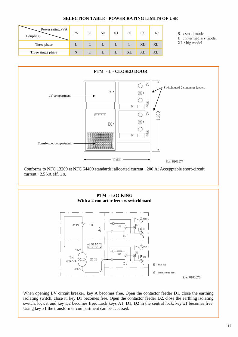
SELECTION TABLE - POWER RATING LIMITS OF USE
PTM - L - CLOSED DOOR
LV compartment
Switchboard 2 contactor feeders
Transformer compartment
Conforms to NFC 13200 et NFC 64400 standards; allocated current : 200 A; Accepptable short-circuit
current : 2.5 kA eff. 1 s.
Plan 8101677
PTM - LOCKING
With a 2 contactor feeders switchboard
When opening LV circuit breaker, key A becomes free. Open the contactor feeder D1, close the earthing
isolating switch, close it, key D1 becomes free. Open the contactor feeder D2, close the earthing isolating
switch, lock it and key D2 becomes free. Lock keys A1, D1, D2 in the central lock, key x1 becomes free.
Using key x1 the transformer compartment can be accessed.
Plan 8101676
Free key
Imprisonned key
18
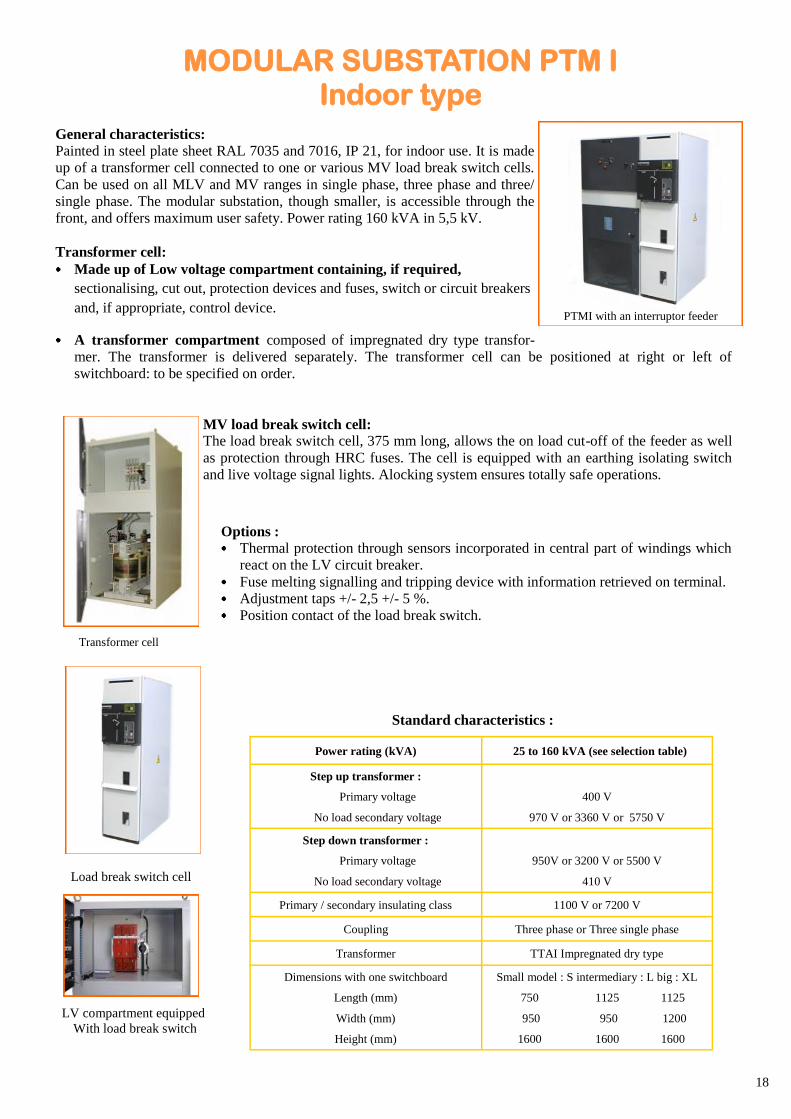
General characteristics:
Painted in steel plate sheet RAL 7035 and 7016, IP 21, for indoor use. It is made
up of a transformer cell connected to one or various MV load break switch cells.
Can be used on all MLV and MV ranges in single phase, three phase and three/
single phase. The modular substation, though smaller, is accessible through the
front, and offers maximum user safety. Power rating 160 kVA in 5,5 kV.
Transformer cell:
Made up of Low voltage compartment containing, if required,
sectionalising, cut out, protection devices and fuses, switch or circuit breakers
and, if appropriate, control device.
A transformer compartment composed of impregnated dry type transfor-
mer. The transformer is delivered separately. The transformer cell can be positioned at right or left of
switchboard: to be specified on order.
MV load break switch cell:
The load break switch cell, 375 mm long, allows the on load cut-off of the feeder as well
as protection through HRC fuses. The cell is equipped with an earthing isolating switch
and live voltage signal lights. Alocking system ensures totally safe operations.
Options : Thermal protection through sensors incorporated in central part of windings which
react on the LV circuit breaker.
Fuse melting signalling and tripping device with information retrieved on terminal.
Adjustment taps +/- 2,5 +/- 5 %.
Position contact of the load break switch.
Standard characteristics :
Power rating (kVA) 25 to 160 kVA (see selection table)
Step up transformer :
Primary voltage
No load secondary voltage
400 V
970 V or 3360 V or 5750 V
Step down transformer :
Primary voltage
No load secondary voltage
950V or 3200 V or 5500 V
410 V
Primary / secondary insulating class 1100 V or 7200 V
Coupling Three phase or Three single phase
Transformer TTAI Impregnated dry type
Dimensions with one switchboard
Length (mm)
Width (mm)
Height (mm)
Small model : S intermediary : L big : XL
750 1125 1125
950 950 1200
1600 1600 1600
Transformer cell
Load break switch cell
LV compartment equipped
With load break switch
PTMI with an interruptor feeder
MODULAR SUBSTATION PTM I Indoor type
19
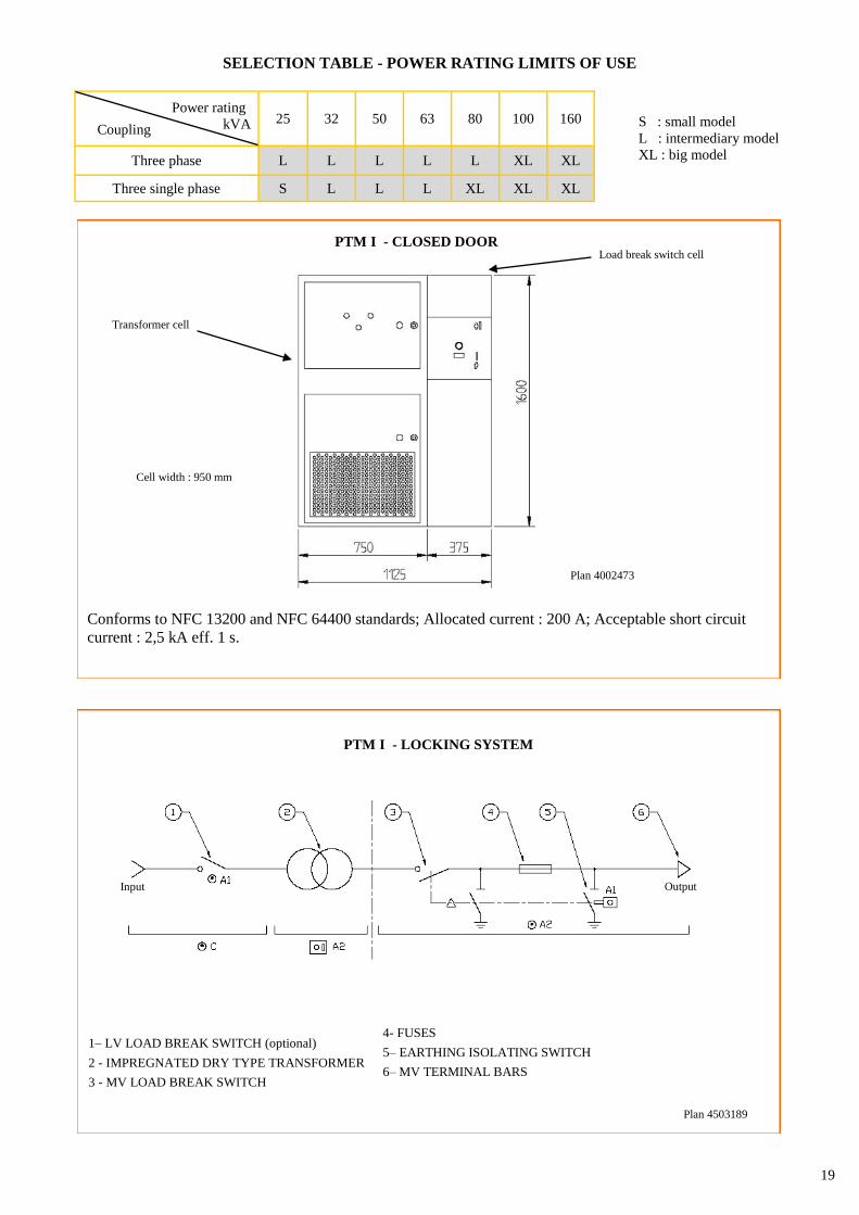
Coupling
Power rating
kVA 25 32 50 63 80 100 160
Three phase L L L L L XL XL
Three single phase S L L L XL XL XL
SELECTION TABLE - POWER RATING LIMITS OF USE
S : small model
L : intermediary model
XL : big model
PTM I - CLOSED DOOR
Conforms to NFC 13200 and NFC 64400 standards; Allocated current : 200 A; Acceptable short circuit
current : 2,5 kA eff. 1 s.
Plan 4002473
Cell width : 950 mm
Transformer cell
Load break switch cell
PTM I - LOCKING SYSTEM
1– LV LOAD BREAK SWITCH (optional)
2 - IMPREGNATED DRY TYPE TRANSFORMER
3 - MV LOAD BREAK SWITCH
4- FUSES
5– EARTHING ISOLATING SWITCH
6– MV TERMINAL BARS
Plan 4503189
TIT Output Input
20
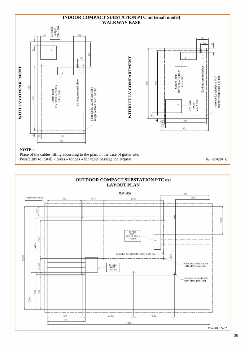
OUTDOOR COMPACT SUBSTATION PTC ext
LAYOUT PLAN
Plan 40 02482
NOTE :
Place of the cables lifting according to the plan, in the case of gutter use.
Possibility to install « press « toupes » for cable passage, on request.
INDOOR COMPACT SUBSTATION PTC int (small model)
WALKWAY BASE
Plan 40 01864 C
WIT
HO
UT
LV
CO
MP
AR
TM
EN
T
Cab
les
inp
ut
HV
320
0 o
r 5500 V
140 x
300
Ear
thin
g t
erm
inal
pla
ce
4 t
hre
aded
, se
aled
pin
s M
14
heig
ht
wit
ho
ut
bas
e :
40 m
m
LV
cab
les
inp
ut
250 x
300
WIT
H L
V C
OM
PA
RT
ME
NT
Cab
les
inp
ut
HV
320
0 o
r 5500 V
140 x
300
Ear
thin
g t
erm
inal
pla
ce
6 t
hre
aded
n,
seal
ed p
ins
M14
heig
ht
wit
ho
ut
bas
e :
40 m
m
LV
cab
le
outp
ut
250 x
300
LV
cab
le
outp
ut
250 x
300
21
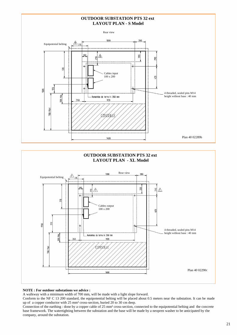
NOTE : For outdoor substations we advice : A walkway with a minimum width of 700 mm, will be made with a light slope forward.
Conform to the NF C 13 200 standard, the equipotential belting will be placed about 0.5 meters near the substation. It can be made
up of a copper conductor with 25 mm² cross-section, buried 20 to 30 cm deep.
Connection of the earthing : done by a copper cable of 25 mm² cross-section, connected to the equipotential belting and the concrete
base framework. The watertighting between the substation and the base will be made by a neopren washer to be anticipated by the
company, around the substation.
OUTDOOR SUBSTATION PTS 32 ext
LAYOUT PLAN - S Model
Plan 40 02289b
4 threaded, sealed pins M14
height without base : 40 mm
Cables input
100 x 200
Rear view
Equipotenial belting
OUTDOOR SUBSTATION PTS 32 ext
LAYOUT PLAN - XL Model
Plan 40 02290c
Rear view
Equipotential belting
Cables output
100 x 200
4 threaded, sealed pins M14
height without base : 40 mm
22
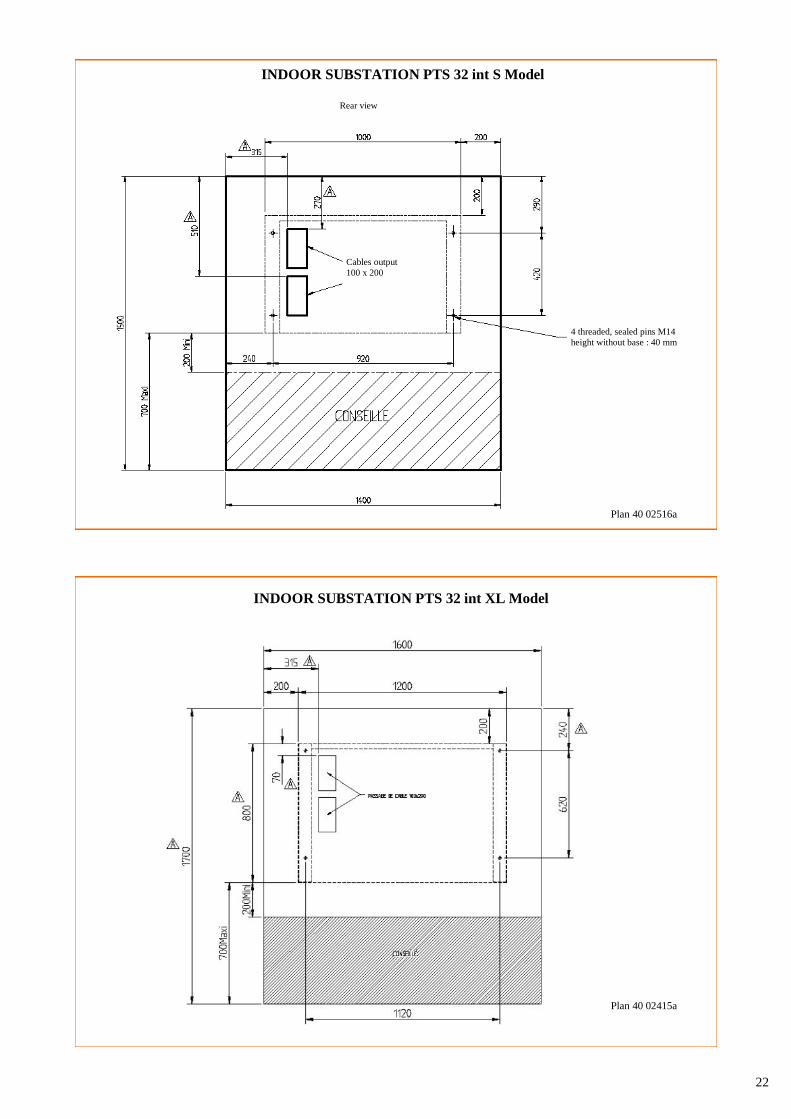
INDOOR SUBSTATION PTS 32 int XL Model
Plan 40 02415a
INDOOR SUBSTATION PTS 32 int S Model
Plan 40 02516a
4 threaded, sealed pins M14
height without base : 40 mm
Cables output
100 x 200
Rear view
23
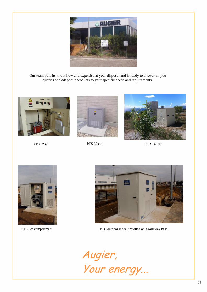
PTC LV compartment PTC outdoor model installed on a walkway base..
Our team puts its know-how and expertise at your disposal and is ready to answer all you
queries and adapt our products to your specific needs and requirements.
Augier, Your energy...
PTS 32 ext PTS 32 int PTS 32 ext
24
AUGIER IS CERTIFIED ISO 9001 SINCE 1995
Wit
h c
onst
ant
impro
vem
ents
, th
e m
anu
fact
ure
r m
ay a
lter
info
rmat
ion w
itho
ut
pri
or
war
nin
g.


