PIPER Introduction and Customer Charter .........................................................................................1 Why you need a dynamometer for vehicle, plant or engine testing......................................................2 PIPER P1200 Dynamometer................................................................................................................3 PIPER P2400 Dynamometer...............................................................................................................4 PIPER P4000 Dynamometer................................................................................................................5 Fixed base mounting adapters..............................................................................................................6 PIP ER DC 720 Dynamometer..............................................................................................................7 PIPER Rail engine Test System...........................................................................................................8 PIPER P1400 Heavy Duty Chassis Dynamometer .............................................................................9 Power curves .......................................................................................................................................10 Torque curves ......................................................................................................................................11 Drive assembly ....................................................................................................................................12 PIPER Dynamometer Instrumentation ...............................................................................................13 P15 EDA & P 15 Instrumentation Configuration .................................................................................14 Installation Requirements....................................................................................................................15
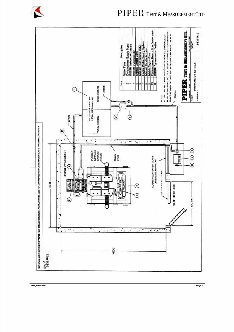
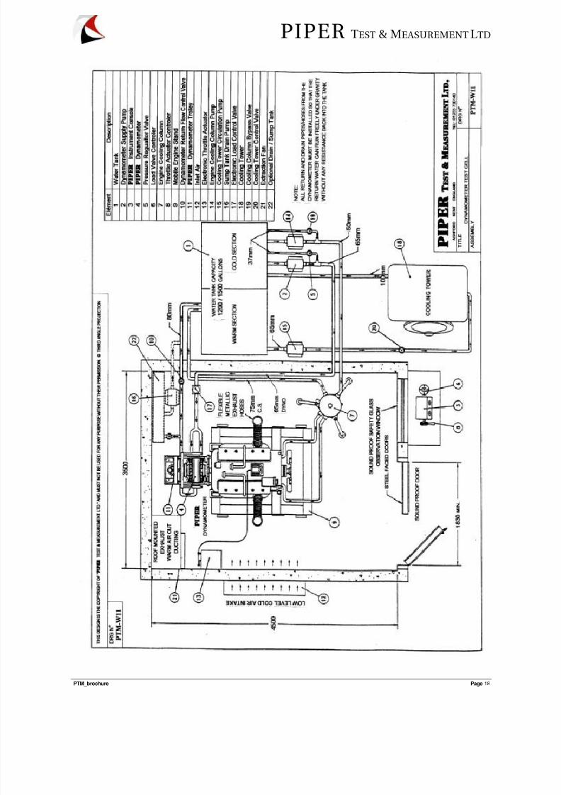
General.............................................................................................................................................15 1. Water tank................................................................................................................................15 2. Dynamometer supply pump.....................................................................................................16 3.
Piper Test & Measur ement manufactures engine test systems with its own product range such as thesuccessful P1200, P2400 and P4000 engine dynamometers, CD1000 and CD2000 chassis dynamometers,and its associated instruments. Our instrumentation range is comprehensive and ranges from simpleanalogue to full computer based data acquisition systems. The majority of the basic equipment can bespecified to incorporate RS232/485 output signals.
The extensive knowledge gained during hands on experience with the workings of hydraulic, eddy current andDC absorption units, enables us to recommend an upgrade to PIPER instrumentation for existinginstallations.
One-off specific test rigs are designed in close co-operation with the customer. Our knowledge of mechanical,electrical and hydraulic systems enables value for money units to be manufactured at short lead times, whilstour close co-operation with engine manufacturers enables the most suitable test schedules to be prepared.
Our co-operation with proprietary peripheral instruments manufacturers of products such as smoke densityrecorders and fuel flow measuring devices, enables PIPER to offer its customers essential test roomequipment.
Technical back-up and assistance with peripheral services and, if required, liaison with subcontractors,ensures that customer experiences the minimum delay once the equipment is delivered on site.
The PIPER design philosophy is based on incorporating known technologies. This ensures that the clienthas reliable, serviceable and, above all, user friendly equipment.
Piper Test & Measur ement is conveniently situated in the South East of England one and two hoursrespectively from Gatwick and Heathrow airport and half an hour from the ferry and tunnel links with Europe.
CUSTOMER CHARTER
The value of customer service is embedded within the culture of our organization and is apersonal belief of every staff member.
• We recognise that our customers are an important asset
• We are committed to providing an effective and efficient service
• We provide leading edge technology through proven engineering concepts
• We have the flexibility to cater for the specialised needs of our customers
• We pride ourselves on our reputation and integrity
• We are proud that our products contribute to a cleaner environment
Why you need a dynamometer for vehicle, plant or engine testing
A dynamometer is a vital requirement for any efficient and reputable service or repair facility. Anecessity to meet manufacturers standard and to enable "end of product" questionnaires to becompleted.
In today's environment it cannot be judged a luxury. It is a recommendation by diesel enginemanufacturers who are conscious of both the environment and ensuring that they give their endusers a product and service on which they can depend. With operating costs escalating in allaspects where the diesel is used, excessive downtime, especially come-backs cannot be tolerated,in addition to causing a financial drain with which customers and facilities cannot live.
A dynamometer, especially a non-fixed base item, will pay for itself in a short period of time. It willallow the engine to be tested under load (even in the chassis) where the majority of the faults willoccur. Problems that arise, which lead to come-backs, are usually diagnosed within the first hoursof operation under load. Dynamometer testing can isolate these problems, verify repairs, while atthe same time establishing power levels.
The ability to pin point problems through objective testing rather than by opinions is the
dynamometers biggest advantage.
The portable PIPER engine dynamometer has several advantages over the convetionallymounted dynamometer.
1. Inexpensive to install
2. Can be mounted directly on the engine bellhousing or with adaptors directly after thetransmission
3. Easier to pin-point performance losses - as drive train is not subjected to load
4. Ideal for investigative projects
The reasons for a portable Dynamometer facility can be summarised as follows:• Trouble shooting and problem isolation
• Reduces come back
• Power compliant verifications
• Fluid leak detection
• Cooling system check-out
• Smoke test
• Adjustment of injection equipment under load to optimize fuel economy
• Run in after overhaul
• Inexpensive for feasibility studies
• Easy to use and flexible in attachment
• No civil engineering costs to be incurred as associated with fixed bed dynamometer
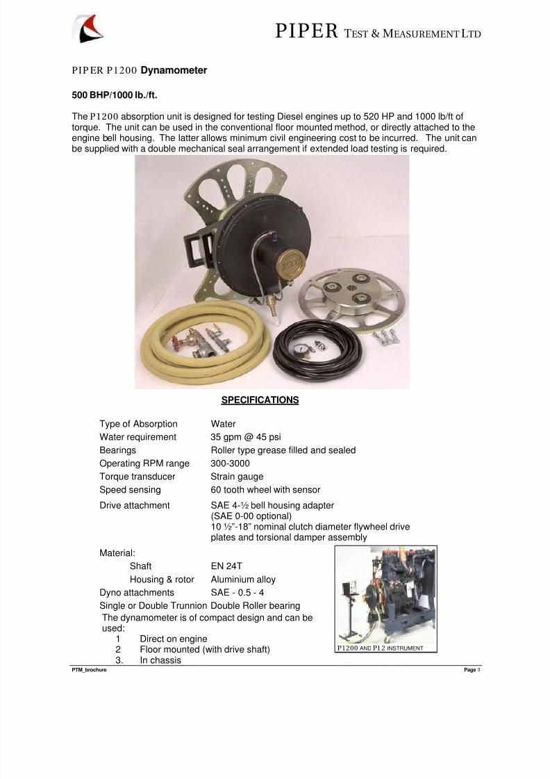
The P1200 absorption unit is designed for testing Diesel engines up to 520 HP and 1000 lb/ft oftorque. The unit can be used in the conventional floor mounted method, or directly attached to the
engine bell housing. The latter allows minimum civil engineering cost to be incurred. The unit canbe supplied with a double mechanical seal arrangement if extended load testing is required.
The dynamometer is of compact design and can beused:
1 Direct on engine2 Floor mounted (with drive shaft)3. In chassis
P1200 AND P1 2 INSTRUMENT
SPECIFICATIONS
Type of Absorption Water
Water requirement 35 gpm @ 45 psi
Bearings Roller type grease filled and sealed
Operating RPM range 300-3000
Torque transducer Strain gauge
Speed sensing 60 tooth wheel with sensor
Drive attachment SAE 4-½ bell housing adapter(SAE 0-00 optional)10 ½”-18” nominal clutch diameter flywheel driveplates and torsional damper assembly
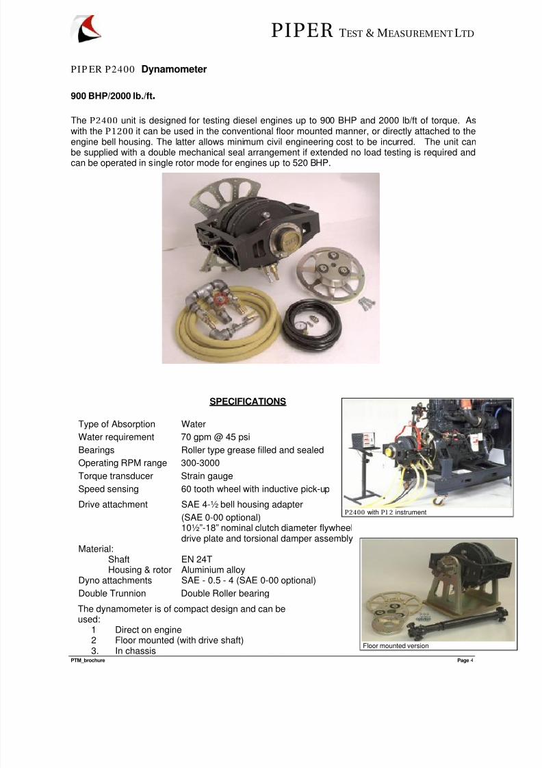
The P2400 unit is designed for testing diesel engines up to 900 BHP and 2000 lb/ft of torque. As
with the P1200 it can be used in the conventional floor mounted manner, or directly attached to theengine bell housing. The latter allows minimum civil engineering cost to be incurred. The unit canbe supplied with a double mechanical seal arrangement if extended no load testing is required andcan be operated in single rotor mode for engines up to 520 BHP.
The dynamometer is of compact design and can beused:
1 Direct on engine2 Floor mounted (with drive shaft)3. In chassis
Floor mounted version
P2400 with P1 2 instrument
SPECIFICATIONS
Type of Absorption Water
Water requirement 70 gpm @ 45 psi
Bearings Roller type grease filled and sealed
Operating RPM range 300-3000
Torque transducer Strain gauge
Speed sensing 60 tooth wheel with inductive pick-up
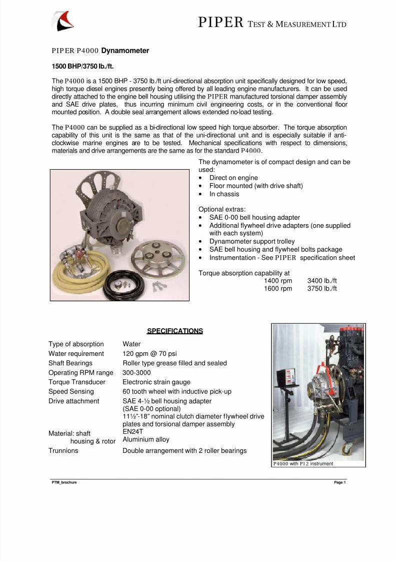
The P4000 is a 1500 BHP - 3750 lb./ft uni-directional absorption unit specifically designed for low speed,high torque diesel engines presently being offered by all leading engine manufacturers. It can be used
directly attached to the engine bell housing utilising the PIPER manufactured torsional damper assemblyand SAE drive plates, thus incurring minimum civil engineering costs, or in the conventional floormounted position. A double seal arrangement allows extended no-load testing.
The P4000 can be supplied as a bi-directional low speed high torque absorber. The torque absorptioncapability of this unit is the same as that of the uni-directional unit and is especially suitable if anti-clockwise marine engines are to be tested. Mechanical specifications with respect to dimensions,materials and drive arrangements are the same as for the standard P4000.
SPECIFICATIONS
Type of absorption Water
Water requirement 120 gpm @ 70 psi
Shaft Bearings Roller type grease filled and sealed
Operating RPM range 300-3000
Torque Transducer Electronic strain gauge
Speed Sensing 60 tooth wheel with inductive pick-upDrive attachment SAE 4-½ bell housing adapter
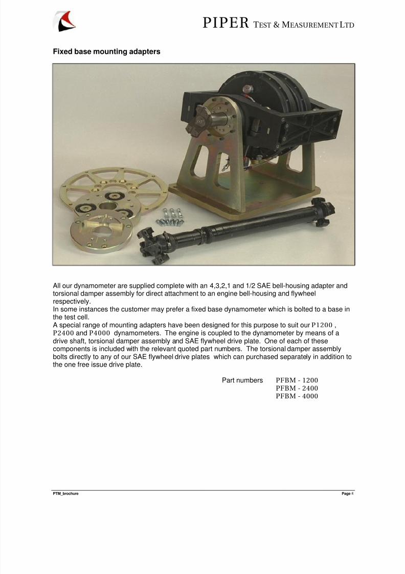
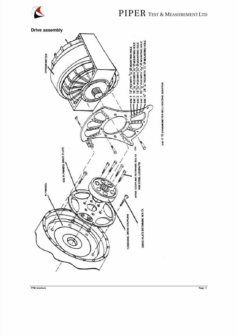
All our dynamometer are supplied complete with an 4,3,2,1 and 1/2 SAE bell-housing adapter andtorsional damper assembly for direct attachment to an engine bell-housing and flywheel
respectively.In some instances the customer may prefer a fixed base dynamometer which is bolted to a base inthe test cell.A special range of mounting adapters have been designed for this purpose to suit our P1200 ,P2400 and P4000 dynamometers. The engine is coupled to the dynamometer by means of adrive shaft, torsional damper assembly and SAE flywheel drive plate. One of each of thesecomponents is included with the relevant quoted part numbers. The torsional damper assemblybolts directly to any of our SAE flywheel drive plates which can purchased separately in addition tothe one free issue drive plate.
The DC720 is a 720 BHP - 2300 lb./ft bi-directional absorption unit specifically designed for low speed,high torque diesel engines presently being offered by all leading engine manufacturers.The DC720 is a fixed base dynamometer with trunnions and strain gauge. It is controlled with a 4
Quadrant thyristor controller and all power absorbed is regenerated into the site electrical supply.No water cooling system is required. This dynamometer can absorb and motor the test engine andis specifically suitable for transient test cycles such as the ETC European Transient CycleELR European Steady Cycle, ESC European Load Response Test and FTP Federal TransientProcedure. A range of alternative sized DC dynamometers is available. Contact for more information.
• 525 kW (720 BHP) Direct Currentdynamometer.
• 3100 Nm torque and 3000 RPMcapability.
• Trunnion mounted with load cell
strain gauge.• Double universal joint drive-shaft and
torsional damper.
• 4 Quadrant Thyristor controllerenabling motoring and absorption.
• Geared Throttle Servo actuator.
Piper Windows based operating softwarein conjunction with InTouch SCADApackage.AK or GPIB protocol modules available forinterfacing with:
Mini tunnel
Fuel meterAirflow meter (hot wire or equivalent)Smoke meterGas analysersWeighing scale
SPECIFICATIONS
Type of absorption Direct Current electrical
Water requirement None
Shaft Bearings Roller type grease filled and sealed
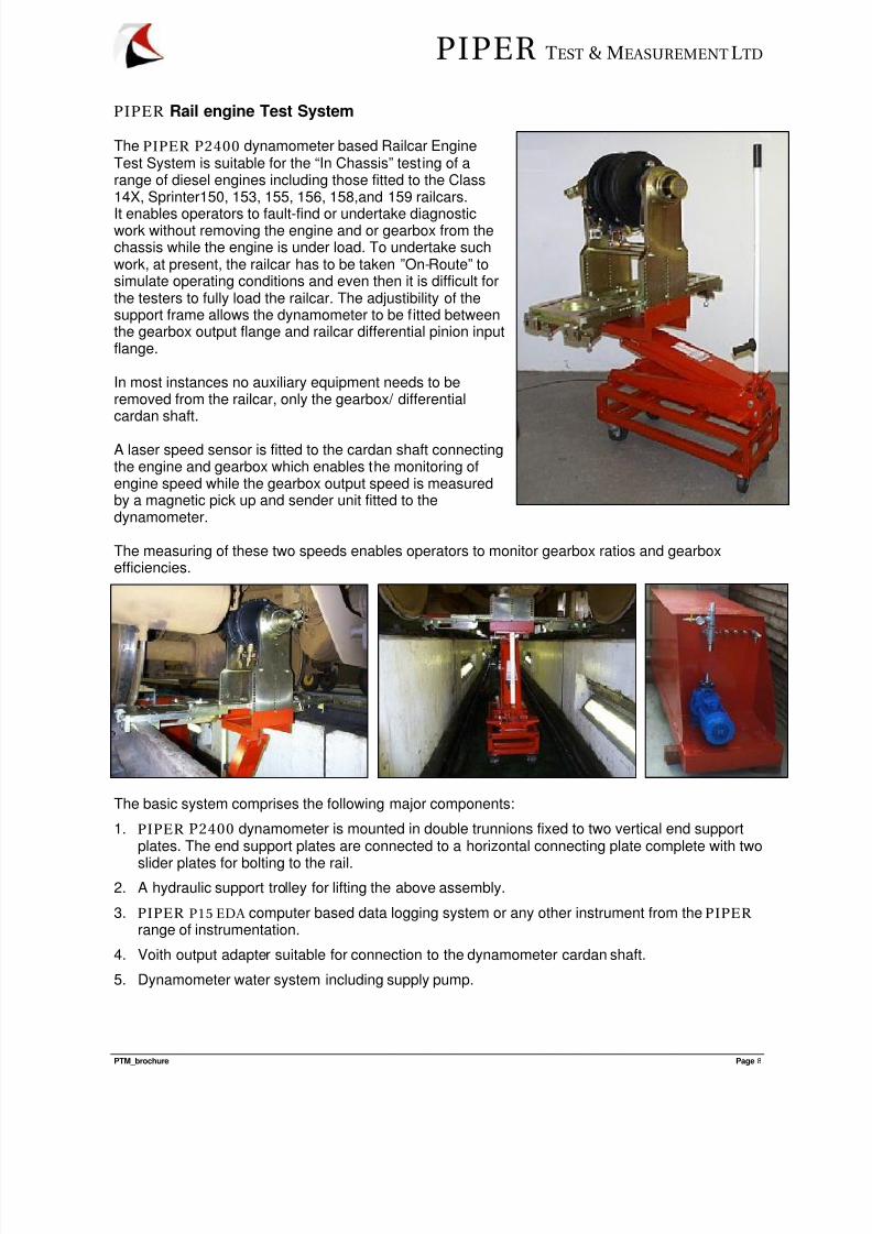
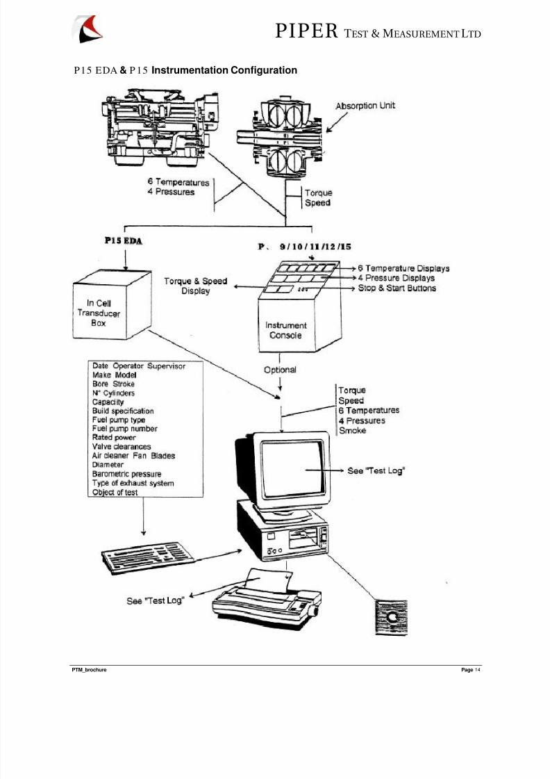
The PIPER P2400 dynamometer based Railcar EngineTest System is suitable for the “In Chassis” testing of arange of diesel engines including those fitted to the Class14X, Sprinter150, 153, 155, 156, 158,and 159 railcars.
It enables operators to fault-find or undertake diagnosticwork without removing the engine and or gearbox from thechassis while the engine is under load. To undertake suchwork, at present, the railcar has to be taken ”On-Route” tosimulate operating conditions and even then it is difficult forthe testers to fully load the railcar. The adjustibility of thesupport frame allows the dynamometer to be fitted betweenthe gearbox output flange and railcar differential pinion inputflange.
In most instances no auxiliary equipment needs to beremoved from the railcar, only the gearbox/ differentialcardan shaft.
A laser speed sensor is fitted to the cardan shaft connectingthe engine and gearbox which enables the monitoring ofengine speed while the gearbox output speed is measuredby a magnetic pick up and sender unit fitted to thedynamometer.
The measuring of these two speeds enables operators to monitor gearbox ratios and gearboxefficiencies.
The basic system comprises the following major components:
1. PIPER P2400 dynamometer is mounted in double trunnions fixed to two vertical end supportplates. The end support plates are connected to a horizontal connecting plate complete with two
slider plates for bolting to the rail.2. A hydraulic support trolley for lifting the above assembly.
3. PIPER P15 EDA computer based data logging system or any other instrument from the PIPER range of instrumentation.
4. Voith output adapter suitable for connection to the dynamometer cardan shaft.
5. Dynamometer water system including supply pump.
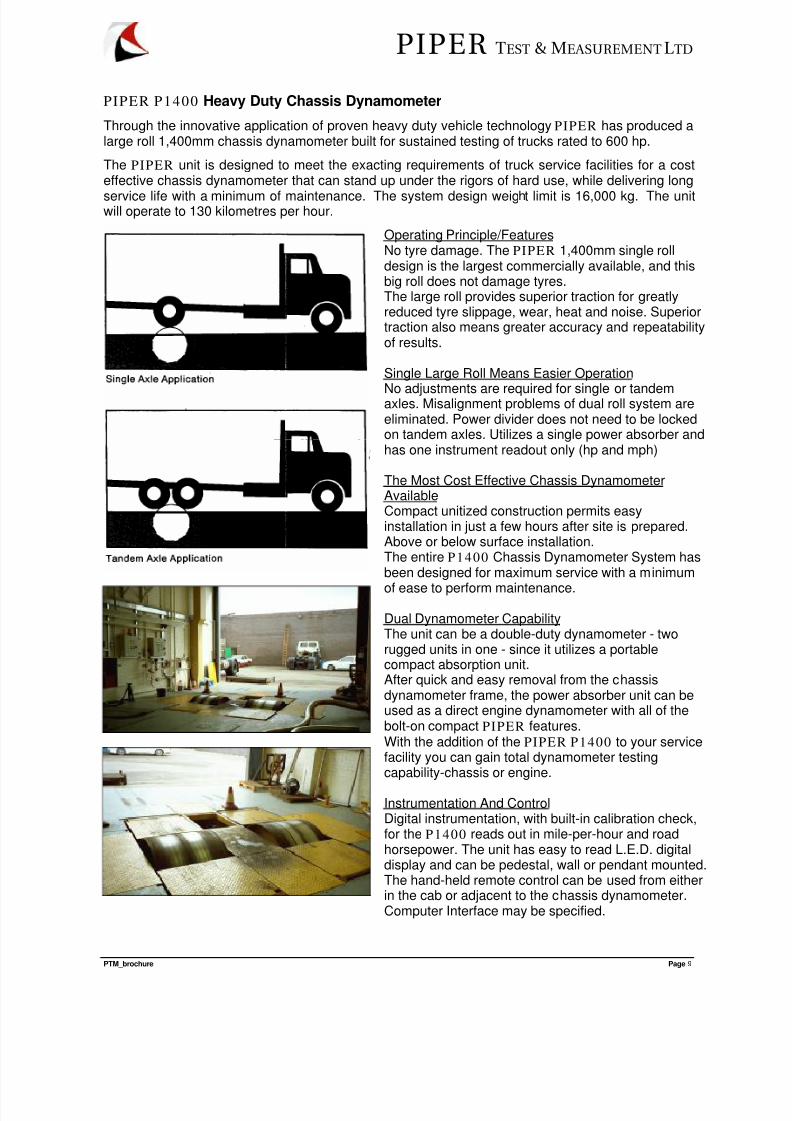
Through the innovative application of proven heavy duty vehicle technology PIPER has produced alarge roll 1,400mm chassis dynamometer built for sustained testing of trucks rated to 600 hp.
The PIPER unit is designed to meet the exacting requirements of truck service facilities for a costeffective chassis dynamometer that can stand up under the rigors of hard use, while delivering long
service life with a minimum of maintenance. The system design weight limit is 16,000 kg. The unitwill operate to 130 kilometres per hour.
Operating Principle/FeaturesNo tyre damage. The PIPER 1,400mm single rolldesign is the largest commercially available, and thisbig roll does not damage tyres.The large roll provides superior traction for greatlyreduced tyre slippage, wear, heat and noise. Superiortraction also means greater accuracy and repeatabilityof results.
Single Large Roll Means Easier Operation
No adjustments are required for single or tandemaxles. Misalignment problems of dual roll system areeliminated. Power divider does not need to be lockedon tandem axles. Utilizes a single power absorber andhas one instrument readout only (hp and mph)
The Most Cost Effective Chassis DynamometerAvailableCompact unitized construction permits easyinstallation in just a few hours after site is prepared.Above or below surface installation.The entire P1400 Chassis Dynamometer System hasbeen designed for maximum service with a minimum
of ease to perform maintenance.
Dual Dynamometer CapabilityThe unit can be a double-duty dynamometer - tworugged units in one - since it utilizes a portablecompact absorption unit.After quick and easy removal from the chassisdynamometer frame, the power absorber unit can beused as a direct engine dynamometer with all of thebolt-on compact PIPER features.With the addition of the PIPER P1400 to your servicefacility you can gain total dynamometer testingcapability-chassis or engine.
Instrumentation And ControlDigital instrumentation, with built-in calibration check,for the P1400 reads out in mile-per-hour and roadhorsepower. The unit has easy to read L.E.D. digitaldisplay and can be pedestal, wall or pendant mounted.The hand-held remote control can be used from eitherin the cab or adjacent to the chassis dynamometer.Computer Interface may be specified.
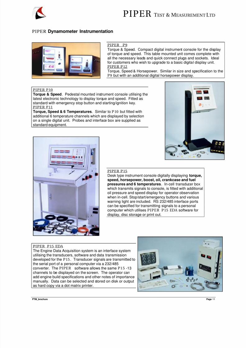
PIPER P9 Torque & Speed. Compact digital instrument console for the displayof torque and speed. This table mounted unit comes complete withall the necessary leads and quick connect plugs and sockets. Idealfor customers who wish to upgrade to a basic digital display unit.PIPER P12 Torque, Speed & Horsepower. Similar in size and specification to theP9 but with an additional digital horsepower display.
PIPER P10 Torque & Speed. Pedestal mounted instrument console utilising thelatest electronic technology to display torque and speed. Fitted asstandard with emergency stop button and starting/ignition key.PIPER P11 Torque, Speed & 6 Temperatures. Similar to P10 but fitted withadditional 6 temperature channels which are displayed by selection
on a single digital unit. Probes and interface box are supplied asstandard equipment.
PIPER P15 Desk type instrument console digitally displaying torque,speed, horsepower, boost, oil, crankcase and fuel
pressures and 6 temperatures. In-cell transducer boxwhich transmits signals to console, is fitted with additionaloil pressure and speed display for operator observationwhen in-cell. Stop/start/emergency buttons and variouswarning light are included. RS 232/485 interface portscan be specified for transmitting signals to a personalcomputer which utilises PIPER P15 EDA software fordisplay, disc storage or print out.
PIPER P15 EDA The Engine Data Acquisition system is an interface systemutilising the transducers, software and data transmissiondeveloped for the P15 . Transducer signals are transmitted tothe serial port of a personal computer via a 232/485converter. The PIPER software allows the same P15 -13channels to be displayed on the screen. The operator canadd engine build specifications and other notes of importancemanually. Data can be selected and stored on disk or outputas hard copy via a dot matrix printer.
For the successful operation of the equipment an adequate water supply is necessary.
The power absorbed by the dynamometer is converted into heat and carried away by the water flowingthrough it. It is an efficient and inexpensive method and the heat generated is directly proportional to thepower absorbed.
Water is therefore an essential element and, as large quantities of hot water are produced, it must be cooledand recycled or disposed. To dispose of large quantities of water may not only be illegal but also wasteful.
In many cases a simple, large, inexpensive plastic or steel storage tank without any heat dispersion fac ility,such as a cooling tower or heat exchanger, may be used. The dynamometer is supplied, via a pressure pump,from this tank. The hot water is then returned to the tank. However, the power and subsequent heatgenerated by the dynamometer and engine will gradually increase the tank water temperature, but if shortperiods of testing are the norm, this facility will suffice. See temperature calculations for factual values.
The size of the tank will depend on the anticipated duration of the test and the power level at which the testwill be performed. From these parameters the volume of the tank can be calculated. It is essential to ensurethat the temperature levels do not exceed 180°F (80°C) at any point in the system.
As a rule of thumb, 100 BHP generates 4242 BTU/min (74447 watts) and if no heat exchanger is available a1000 gallon (4540 lt.) tank will enable a 100 BHP engine to run for 4 hours assuming a starting tank watertemperature of 120°F (50°C). A 500 BHP engine can run for ±50 minutes before unacceptable tank watertemperatures are reached.
If extended periods of testing are required, a surface evaporating cooling tower will need to be fitted within thesystem. This would not waste any water but will require an initial financial outlay. To maintain a constant tanktemperature, the cooling tower must be capable of coping with 320000 BTU/hrs for every 100 BHP absorbedby the dynamometer and engine cooling system..
The following will offer some explanation as to the requirement and specification of the various components
which make up a successful facility. Please do not hesitate to contact PIPER if in doubt.
1. Water tankThe water tank can be manufactured from plate steel (protected against corrosion), plastic, concrete(suitably sealed) or any other material able to withstand temperatures up to 195°F (90°C) and notaffected by an antifreeze solution. The tank is not subjected to any pressure other than the weight ofwater in it and therefore does not require any certification. A baffle in the middle of the tank will createa hot and cold well. This baffle acts as a buffer but not a sealant between the two wells. It separatesthe cold water required to supply the dynamometer and the engine cooling system from the returnedhot water. If a cooling tower is fitted, the hot water is circulated through the cooling tower while thecooled water is returned to the cold well.
The location of the tank is important. It is essential that the water level in the tank is below the outletport of the dynamometer so that the water can run freely away from it without any back pressure. Any
resistance in the return lines will create overheating of the dynamometer and can cause seriousdamage. The location of the tank will influence the actual overall dimensions of it. If a pit can beexcavated, the overall surface area required can be kept to a minimum as the depth of the pit will giveincreased height and, therefore, volume. While an above ground tank is restricted in depth since thisis dictated by the outlet port height of the dynamometer. This usually dictates a larger surface areafor an equal volume. Ideally the total tank volume required is between 1200 and 1500 gallons, thisequates to between 4.8 and 6 cubic metres respectively. For example, an above ground tank islimited to 0.6 metre in height (to stay below the outlet port of the dynamometer). We therefore requirea surface area of:
This equates to a tank of 2.58 x 2.58 surface area or any other combination which equals to 6.6 sq.metre.
Provision in the tank must be made for the following connections and services:(i) For the Dynamometer pump supply :-
Ideally this should be situated at the bottom of the tank for flooded pump suction or, if thepump is above the water level, a non-return valve will need to be incorporated. Connection incold well.
(ii) For the engine cooling pump supply:-same as (i)
(iii) For the cooling tower heat exchanger supply:-Same as (i) but connection to be in the hot well.
(iv) Tank "top-up" supply from mains:-To be connected in the top of the tank and should enter via ball valve.
(v) Overflow - at least 2½ times the diameter of the mains supply.(vi) Cooling tower return - water for the cooling tower usually free-falls through the tower back into
the cold well of the tank and generally does not require any fixed connections into the tank.
2. Dynamometer supply pump The pump should be mounted with its inlet or suction port below the level of the water in the tank sothat a non-return valve is not required and the pump can therefore operate with a constant head ofwater. The pump is required to supply the P1200, P2400 and P4000 dynamometer with 45GPM(205lt/min), 90gpm(410lt/min) at 45psi (3.2kg/cm²) dynamic( (flowing pressure) and 140GPM/640lt/min) at 70psi (4.8kg/cm²) dynamic respectively. Pump suppliers will require the followinginformation:-i) The distance from the water tank to the dynamometer including the pipe diameters and
length.
ii) The height from the pump to the dynamometer inlet port. Suction must be from the cold
section of the tank. 3. PIPER instrument consoles
See P9, P10 , P11 , P12 , P 15 and P15 EDA instrumentation specification sheets.
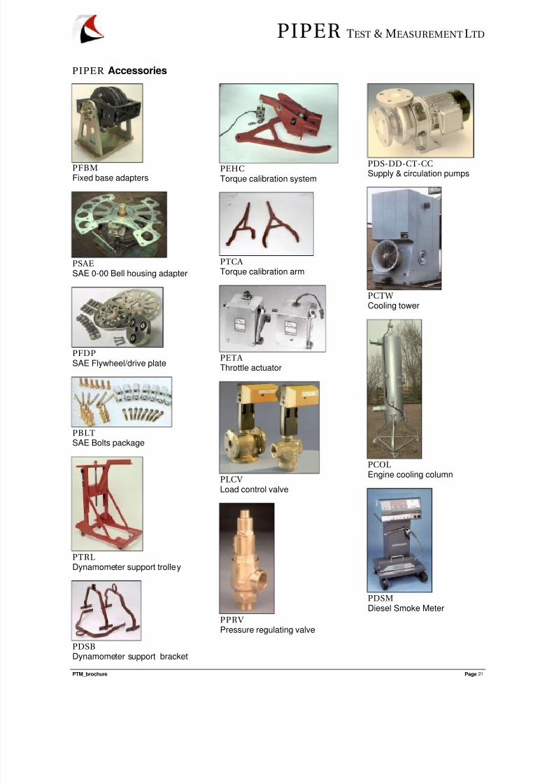
4. PIPER dynamometersP1200, P2400 and P4000 absorption unit are bolted directly onto and close coupled to the engine.Floor mounted adapters and drive shafts are available for all models. See dynamometer specificationsheets.
5. Pressure regulating valveIt is advisable to fit all the pumps with a by-pass system so that when the load control valve to thedynamometer and thermo-static valve to the engine cooling column are closed, water can return tothe tank without continually pressurising the pumps. These by-pass control pipes and valves are teedoff the outlet port of the pumps and allow water to return to the cold well of the tank. An automatic
pressure regulating valve supplied byPIPER
(contact factory) or stopcock valve will suffice for by-pass water flow control.
7. Engine cooling column or radiatorEither an PIPER engine cooling column, radiator or overhead tank is required to control the enginewater jacket temperature. To control this temperature a cooling column has been designed to controlengine water temperatures for engines up to 1500 BHP. The water system operating pressure can becontrolled between 5 and 40 p.s.i. by means of an adjustable pressure relief valve activated by ahandle at the bottom of the column. Cool water is introduced from the main tank via a thermostaticallyoperated valve or valves. Hot water returns back to the main tank via this adjustable pressure reliefvalve. A sight glass at the top will indicate if exhaust gases are escaping from a leaking combustionchamber into the engine cooling system. A fill and drain system is incorporated allowing limited lossof water. Water flow and pressures supply to the column are depended on the size of engines to betested. PIPER offer a range of suitable supply pumps which are shown on our Supply and circulationpump product sheet. Alternatively an engine radiator or overhead wall mounted tank may be used. The radiator, of the industrial/stationary installation type, in combination with either an engine orelectrically driven fan, is required to maintaining a constant temperature at full power. Alternatively,an overhead plastic or steel tank with sufficient volume - min 45 gallons must be placed adjacent toand above the front of the engine. Provision must be made in the tank for connection to and from theengine. An overflow and supply connection will also be needed. The supply can be controlled by a
thermo-static valve.
8. Throttle actuator controllerSee point 13.
9. Mobile engine test stand.PIPER manufacture a engine support stand suitable for a wide range of engines. The engine can betested in a relative light frame as all the torque reactions are retained within the engine / dynamometerpackage. Contact factory for specific details.
10. Dynamometer return flow control valve.It is recommended to fit a manual control valve in the dynamometer water return pipe. (or pipes if theP2400 is fitted) This valve size depends on the model of the dynamometer used. Contact factory forfurther details.
11. Dynamometer support trolleyThis trolley supports the dynamometer when not attached to an engine. It prevents accidentaldamage and is adjustable for height and easy dynamometer alignment to the engine bell - housing.The trolley is fitted with two steering and two fixed wheel castors.
12. Inlet airInlet air should enter the test cell just above ground level via trunking attached to, or incorporated inthe test cell wall. Louvered vents, adjustable from the cell, will allow the trunking to be shut off fromthe atmosphere when not in use. Typical cross area dimensions for the trunking, if two are fitted,would ± 2 sq.ft. each.
13. Electronic throttle actuatorFor remote operation of an engine throttle or fuel pump control rack, PIPER offer a push - pullmanual throttle cable and handle or alternatively an electronic actuator which can be fitted in the testcell connected to engine throttle lever, by means of a short push - pull cable and operated remotely bya switch or potentiometer mounted on the operator control panel or PIPER instrument. Actuator issupplied for connection to a 24 Vdc supply.
14. Engine cooling column pump
This pump, as with the dynamometer pump, should be mounted so as to operate with a constant headof water. Generally, it may be assumed that it will require to pump a third of the flow and pressure ofthe dynamometer supply pump. Suction is from the cold section of the tank.
15. Cooling tower circulation pumpThis pump, if possible, should be mounted so as to operate with a constant head of water. The inletport of the pump must be connected to the warm section of the tank and sized according to the flowcapability of the cooling tower.
16. Sump tank drain pump. In installations where it is not possible to install a tank with a water level below the outlet port height ofthe dynamometer (preventing water to drain away from the dynamometer without back pressure) anintermediate sump tank is required which allows the water from the dynamometer to flow awaywithout back pressure or resistance. A drain or transfer pump then pumps the water back to the maintank which can now have a water level above the dynamometer outlet port height. We have selecteda range of suitable pumps and we recommend that you contact our factory for details.
17. Load control valveThe absorption capability of the dynamometer is directly proportional to the water passed through theunit which is controlled by a mechanical load valve in the system. This valve may be situated in theoperator control area and is mounted in the water pipe between the dynamometer supply pump andthe dynamometer. In some instances its positioning may be difficult to achieve due to the extra pipelength or building restrains. As an alternative to this manual valve we can offer a remote electronicvalve which may be placed in a more convenient position and which allows the opportunity toeliminates the water pipes from entering the operator control area. Control of this valve is by switch orposition potentiometer and requires a 24 Vdc supply.
18. Cooling TowerPIPER can supply a range of cooling towers developed for use with our dynamometers. The sizingof these towers depends very much on local climatic conditions and may vary from our recommendedunits. We will require local humidity and average temperatures to advise on the most suitable unit.
Please contact the factory for further detailsThese units combined with its circulation pump, is an optional extra. It will need to be considered ifextended test periods are required. Water is pumped from the warm well in the tank to the top of thetower where it falls over a broken surface and, with the aid of a fan, heat is evaporated and the cooledwater is returned to the main tank. A local cooling tower manufacturer or supplier will require thefollowing information before recommending the most suitable unit for a particular duty andenvironment.(i) Flow through tower. As a separate circulation pump is used for the tower the manufacturer
should be able to advise on the tower flow capability. This information will be required by thepump supplier to size the cooling tower circulation pump.
(ii) Temperature coolant range:For the system to maintain a constant temperature the cooling tower must be able to dissipate4242 BTU/min for every 100 BHP absorbed in addition to the 1060 BTU/min generated by theengine cooling system or 320000BTU/hr.
(iii) The design ambient and operating altitude will be required for the correct sizing.
19. Cooling column bypass control valve.A manually operated by pass control valve is recommended so that when the cooling columnthermostatically operated control valve is closed, water can return to the tank without continuallypressurising the pumps.
20. Cooling tower control valveThe cooling tower pump is sized to optimise the flow through the cooling tower. However it is
advisable to fit a manual control valve which will allow the operator to reduce the flow if necessary.
21. Extraction fanThe extraction fan and ducting should be mounted high in the test room. The fan motor can drive thefan by means of "V" belts and therefore out of the hot air flow. The installation should be capable of
15000 C.M.F. at 1" static pressure. It is advisable to incorporate a back or aft damper and birdscreen.
22. Drain / sump tankIn installations where it is not possible to install the main tank with a water level below thedynamometer outlet port height, preventing water draining away from the dynamometer without backpressure or resistance, an intermediate sump tank is required which allows the water from thedynamometer to flow away without resistance. This tank may be situated in the test cell as shown onthe diagram and will require a float switch operated transfer pump to pump the water to the main tank