PUBLIC UTILITIES COMMISSION OF THE STATE OF CALIFORNIA SAFETY DIVISION RESOLUTION SU-25 UTILITIES SAFETY BRANCH ANUARY 19, 1994 RESOLUTION RESOLUTION SU-25, ORDER AUTHORIZING RULE CHANGES TO GENERAL ORDERS NOS. 95 AND 128 (G.O.s 95/128), RULES FOR OVERHEAD AND UNDERGROUND ELECTRIC AND COMMUNICATION LINE CONSTRUCTION SUMMARY 1. The staff of the Safety Division's Utilities Safety Branch (USB) requests authorization for changes to G.O. 95 and 128 contained in the enclosed Appendices A and B respectively. 2. The request follows submittal of proposed changes by the General Orders 95/128 Rules Committee, which is composed of representatives from operators of electric and communication lines in California. The committee has obtained a consensus of Investor owned utilities, utility districts, municipalities, the California Cable Television Association, and the associated labor unions concerning the changes. 3. The changes update the General Orders to keep pace with changing technology, and practices in the electric and communications industry. Worker and public safety are always paramount considerations. BACKGROUND 1. The changes are the result of the informal proposals by the General Orders 95/128 Rules Committee. The committee represents operators of overhead and underground lines and the associated labor unions in California. The committee reviews the rules and make changes thru a consensus agreement after careful scrutiny and much debate. All operators are invited to participate in ongoing workshops held in various locations in Northern and Southern California six times annually. Any member has veto power. 2. Members of the USB staff attend meetings of the rules committee and its subcommittees to participate in its discussions and assist in its work. 3. When a study group or subcommittee of the main rules committee drafts a rule change proposal, the entire committee votes on accepting the
Transcript
PUBLIC UTILITIES COMMISSION OF THE STATE OF CALIFORNIA SAFETY DIVISION RESOLUTION SU-25 UTILITIES SAFETY BRANCH ANUARY 19, 1994
RESOLUTION RESOLUTION SU-25, ORDER AUTHORIZING RULE CHANGES TO GENERAL ORDERS NOS. 95 AND 128 (G.O.s 95/128), RULES FOR OVERHEAD AND UNDERGROUND ELECTRIC AND COMMUNICATION LINE CONSTRUCTION SUMMARY 1. The staff of the Safety Division's Utilities Safety Branch (USB) requests
authorization for changes to G.O. 95 and 128 contained in the enclosed Appendices A and B respectively.
2. The request follows submittal of proposed changes by the General Orders
95/128 Rules Committee, which is composed of representatives from operators of electric and communication lines in California. The committee has obtained a consensus of Investor owned utilities, utility districts, municipalities, the California Cable Television Association, and the associated labor unions concerning the changes.
3. The changes update the General Orders to keep pace with changing
technology, and practices in the electric and communications industry. Worker and public safety are always paramount considerations.
BACKGROUND 1. The changes are the result of the informal proposals by the General
Orders 95/128 Rules Committee. The committee represents operators of overhead and underground lines and the associated labor unions in California. The committee reviews the rules and make changes thru a consensus agreement after careful scrutiny and much debate. All operators are invited to participate in ongoing workshops held in various locations in Northern and Southern California six times annually. Any member has veto power.
2. Members of the USB staff attend meetings of the rules committee and its
subcommittees to participate in its discussions and assist in its work. 3. When a study group or subcommittee of the main rules committee drafts
a rule change proposal, the entire committee votes on accepting the
change. The proposal may be modified to obtain consensus of the committee, otherwise the proposal is dropped.
4. After a final draft of the proposed rule changes is approved in committee,
it is then sent to all members for a final vote. Any dissenting vote requires that meetings be held to resolve the issues.
5. Safety is of primary concern when a rule change is proposed.
Representatives from the electric and telecommunications workers labor unions participate in the committee and no rule is passed without their approval.
DISCUSSION 1. The proposed changes are presented in the enclosed Appendix A for G.O.
95 and Appendix ~ for G.O. 128. A list of the rules is contained in the Table of Contents of Appendix A and Appendix B.
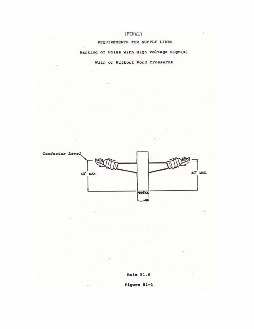
The following sections of the General Orders are affected by the proposal: General Order No.95 rules: 20.5, 20.8, 20.10, 22.2, 23.1, 23.2, 33.2, 38 Table 2, 49.1, 51.6, 52.5, 52.7, .54.4, 54.6, 54.7, 54.12, 58.1, 58.2, 58.3, 58.4, 58.5, 58.6, Section VII, 84.6, 86.4, 91.4, 104, 114, Appendix E, Index. General Order No. 128 rules: 36.3, 36.4
FINDINGS 1. We find that the changes to G.O.s 95 and 128 authorized in this resolution
are just and reasonable. THEREFORE. IT IS ORDERED THAT: 1. The changes in text shown in Appendix A shall be made in G.O. 95, the
changes in text shown in Appendix B shall be made in G.O. 128. 2. All rules changed shall be marked “Revised January 19, 1994 by
Resolution SU-25.” 3. This Resolution is effective today. I hereby certify that this Resolution was adopted by the Public Utilities Commission at its regular meeting on January 19, 1994. The following Commissioners approved it.
NEAL J. SHULMAN EXECUTIVE DIRECTOR
DANIEL Wm .FESSLER President
PATRICIA M. ECKERT NORMAN D .SHUMWAY P .GREGORY CONLON JESSIE J. KNIGHT, Jr.
Commissioners
APPENDIX A
PROPOSED RULE CHANGES
RULES FOR OVERHEAD LINE CONSTRUCTION, GENERAL ORDER NO.95 STATE OF CALIFORNIA PUBLIC UTILITIES COMMISSION
NOTE: (1) For each rule change, the appendix provides the following:
(a) The rationale for the change. (b) The existing rule and the proposed rule changes, with
deletions struck out and additions underlined. (c) The final rule change.
APPENDIX A - TABLE OF CONTENTS
ITEM DESCRIPTION 1. Rules 20.5-A, B Definition of Communication Circuits 2. New Rule 20.10, Definition of Crossing Span 3. Rules 22.2, 20.8, 54.6-C, D, 54.7, 84.6-B, D Suitable Protective Covering 4. Rules 23.1, 23.1-A, 23.2, 23.2-A, Definitions for Terminal Fittings,
termination, and Termination Apparatus 5. Rules 33.2, Ground or Earth as a Conductor 6. Rule 38, Table 2, Case 18; 56.4-C; Guys Approximately Parallel 7. Rule 49.1-C, Setting of Poles 8. Rules 51.6-A, 52.4, Marking of Poles 9. Rule 51.6-B, Guarding of Poles 10. Rules 54.4-G, 52.5, 52.7, 104, 114, Grounded Equipment Clearance
Requirements 11. Rule 54.4-H1, Conductor Clearance from Buildings 12. Rule 54.6-E, Risers 13. Rules 54.6-F, G, H, I, Vertical and Lateral Conductors
14. Rules 54.12-F1, F2, Climbing Space (Including Fig, 54-12) 15. Rule 58.1, Enclosed Equipment Requirements 16. Rule 58.2, Transformer Requirements 17. Rule 58.3, Gang Operated Switches 18. Rule 58.4, Traffic Signals 19. Rule 58.5, Street Light Equipment 20. Rule 58.6, Miscellaneous Equipment 21. Section VII, Section Title, Rule 70, Title Name and Third Rail Operation 22. Rule 84.6-E, Risers 23. Rule 86.4, 86.4-A1, Guys and Anchors- Clearances 24. Rule 91.4, Delete Rule –Cross Reference Rule 54.4-G 25. Appendix E, Clearance from Railroad Tracks 26. Index, Anchor Guy Markers (Formerly Guy Guards)
APPENDIX B
PROPOSED RULE CHANGES
RULES FOR UNDERGROUND LINE CONSTRUCTION, GENERAL ORDER NO.128
STATE OF CALIFORNIA PUBLIC UTILITIES COMMISSION
NOTE: (1) For each rule change, the appendix provides the following:
(a) The rationale for the change. (b) The existing rule and the proposed rule changes, with
deletions struck out and additions underlined. (c) The final rule change.
APPENDIX B - TABLE OF CONTENTS
ITEM DESCRIPTION 1. Rule 36.3, Neutral Conductors 2. Rule 36.4, Ground or Earth as a Conductor
APPENDIX A
RATIONALE FOR PROPOSED RULE CHANGE RULE 20.5-A
DEFINITIONS CLASS C COMMUNICATION CIRCUITS RULE 20.5-B
DEFINITION PRIVATE COMMUNICATION CIRCUITS The existing contents within the definition of Class C Communication Circuits did not reflect modern technology. This proposed Rule change eliminates reference to the division of major and minor Class C circuitry categories made obsolete by such technology. In addition, archaic terms and usages have been supplanted with current terminology. Reformatting of the rule and changing the title to CLASS C COMMUNICATION PUBLIC AND PRIVATE CIRCUITS resulted from these proposed rule changes, which also made it possible for the elimination of Rule 20.5-B. Related rule changes with minor editing are included in this proposal.
EXISTING RULE RULE 20.5-A (1) & (2)
RULE 20.5-A (1) & (2) A Class C Construction means circuits which are used for public or private
communication service and which operate at not exceeding 400 volts to ground nor 750 volts between any two points of the circuit and the transmitted power of which does not exceed 150 watts. When operated at less than 150 volts no limit is placed on the capacity of the system.
Note: Telephone, telegraph, messenger-call, clock, fire or police alarm circuits are included in this classification and other circuits used for signal purposes in which the above limitations are not exceeded may be included. 1 Major Class C Circuits mean communication circuits which
include the following: More than four conductors (open, paired or in cable) used chiefly for local exchange service. Toll telephone or telegraph circuits used for transmission of messages of the general public, and not including clack, messenger call, railway signal, police, fire alarm and other special communication circuits.
2 Minor Class C Circuits mean communication circuits not installed in the definition of Major Class C Circuits. (see Rule 20.5-A1.)
EXISTING RULE (STRIKE OUT AND UNDERLINE)
RULE 20.5-A (1) & (2) RULE 20.5-A (1) & (2) A Class C Construction means circuits which are used for public or private
communication service and which are divided as follows:
1. Current Carrying circuits operate operating at potentials not exceeding 400 volts to ground nor 750 volts between any two points of the circuit and the transmitted power of which does not exceed 150 watts. When operated at less than 150 90 volts, no limit is placed on the capacity of the system. Any circuit which exceeds the above values used for information transport shall be treated as a supply circuit and must meet the supply requirements for the voltage involved.
2. Fiber optic circuits transmitting light for communication purposes
(see definition, Rule 20.3 ).
Note: Information systems including, but not limited to, Telephone, telegraph, messenger-call railroad-signal, data, clock, fire or police alarms, circuits cable television and other systems conforming with the above are included in this classification. and other circuits used for signal purposes in which the above limitations are not exceeded may be included.
1 Major Class C Circuits mean communication circuits which include
the following: More than four conductors (open, paired or in cable) used chiefly for local exchange service. Toll telephone or telegraph circuits used for transmission of messages of the general public, and not including clack, messenger call, railway signal, police, fire alarm and other special communication circuits.
2 Minor Class C Circuits mean communication circuits not installed in the definition of Major Class C Circuits. (see Rule 20.5-A1.)
PROPOSED RULE CHANGE (FINAL)
RULE 20.5-A (1) & (2) RULE 20.5-A (1) & (2) A Class C Construction means circuits used for public or private
communication service and are divided as follows:
1. Current Carrying circuits operating at potentials not exceeding 400 volts to ground nor 750 volts between any two points of the circuit and the transmitted power of which does not exceed 150 watts. When operated at less than 90 volts, no limit is placed on the capacity of the system. Any circuit which exceeds the above values used for information transport shall be treated as a supply circuit and must meet the supply requirements for the voltage involved.
2. Fiber optic circuits transmitting light for communication purposes
(see definition, Rule 20.3).
Note: Information systems including, but not limited to, telephone, railroad-signal, data, clock, fire or police alarms, cable television and other systems conforming with the above are included in this classification.
EXISTING RULE RULE 20.5-B RULE 20.5-B B Private Communication Circuits mean circuits used for private
communication, signal or control service in the operation of other facilities. (see Rules 78.2 and 89.)
EXISTING RULE
(STRIKE OUT AND UNDERLINED) RULE 20.5-B
B INTENTIONALLY LEFT BLANK Private Communication Circuits mean
circuits used for private communication, signal or control service in the operation of other facilities. (see Rules 78.2 and 89.)
PROPOSED RULE CHANGE
(FINAL) RULE 20.5-B
B INTENTIONALLY LEFT BLANK
RELATED RULE CHANGES Associated Rule changes with 20.5-A & B Reference Location Old Reference New Reference Rule 32.4-C 20.5-B 20.5-A Rule 78.2 20.5-B 20.5-A Rule 89.1 20.5-B 20.5-A Rule 42, Table 3, 4th line Delete “Major” Table 3, 16th line Delete “Major” Table 3 17th line Delete Entire Line Rule 83.4 7th line Delete “Major and Minor” Rule 89.2, 8th line Delete “Minor”
RATIONALE FOR PROPOSED RULE CHANGE (New Rule 20.10)
The term “crossing span” appears in several sections of General Order 95, but there is not a definition of a crossing span in section II. Rule 20.10 will provide a definition for “Crossing Span”
EXISTING RULE (RULE 20.10)
None New Rule
PROPOSED RULE CHANGE (STRIKE OUT AND UNDERLINED)
Rule 20.10 20.10 Crossing Span (spans in crossing) means cables, conductors, messengers,
span wires, or guys that cross other cables, conductors, messengers, span wires, or guys that are not supported on the same poles or structures.
PROPOSED RULE CHANGE
(FINAL) Rule 20.10 20.10 Crossing Span (spans in crossing) means cables, conductors, messengers,
span wires, or guys that cross other cables, conductors, messengers, span wires, or guys that are not supported on the same poles or structures.
RATIONALE FOR PROPOSED RULE CHANGE RULE 22.2
SUITABLE PROTECTIVE COVERING Based on tests at the PG&E test facility (test reports enclosed), the proposed changes exact the definition of suitable protective covering by stating the explicit impact strength and insulating efficiency of 1.5 inches of redwood. This minimum strength and insulation criteria for redwood are now to be the minimum requirements for all wood materials not specifically stated in Rule 22.2. Prior to this rule change, all material not specifically stated in the definition was related in some degree to redwood, but no clear strength and insulation criteria was ever explicitly stated for redwood. Thus, it was difficult to determine if a given new material met the requirements of Rule 22.2. With the proposed rule change, other woods not now specifically stated in the definition now can be used as long as they meet the minimum requirements in the revised definition. Also, other synthetic materials not specifically stated in the rule now can be used as long as they meet the minimum requirements for synthetic material in the revised definition. Besides making appropriate changes throughout G.O. 95 as relating to the revised wording in Rule 22.2, the text was restructured, reformatted, and minor changes were made in syntax.
EXISTING RULE Rule 22.2
22.2 PROTECTIVE COVERING, Suitable, means a covering of wood, or other
material as authorized by the Public Utilities Commission, having the electrical insulating efficiency and mechanical strength of 1 ½ inches of redwood. Materials meeting the requirements of this definition, when installed in a workmanlike manner include:
A. IMPREGNATED FIBER CONDUIT, having a wall thickness of not less
than one quarter of an inch, installed over rigid metal conduit as illustrated in Figure 83 of Appendix G.
B. HARDWOOD MOULDING (oak or rock elm) three eights of an inch in thickness, or having a cross-section as shown in Figure 81 of Appendix G, when used as a covering for ground wires and communication conductors. Douglas Fir moulding ½-inch in thickness shall be considered as meeting the requirements of this rule for suitable protection of ground and bond wires.
C. PLASTIC PIPE made of rigid unplasticized polyvinyl chloride having
the properties and dimensions specified as EPC-40-PVC and EPC-80-PVC in NEMA Standards. The plastic pipe herein specified shall be installed only outside the climbing space on poles or structures unless installed in accordance with Rule 54.6-C2.
D RIGID U-SHAPED MOULDING made of unplasticized polyvinyl
chloride having the properties and physical characteristics specific for plastic pipe (Rule 22.2-C). The plastic moulding herein specified shall be installed only outside the climbing space on poles or structures.
E. RIGID U-SHAPED GROUND WIRE MOULDING made of polyvinyl
chloride having the properties specified as Class 14333-D in ASTM Standard D1784-69. The plastic moulding herein specified shall be installed only outside the climbing space on the surface of wood poles or structures and shall have dimensions as shown in Figure 82 of Appendix G, and shall effectively contain and entrap the ground wire. Moulding shall be marked with wire size (e.g., AWG 6) at intervals of not more than four feet.
F BOLT COVERS made of non-conducting shield or covering shield or covering having the insulating efficiency and mechanical strength of impregnated fiber not less than 5/16 of an inch thick.
Proposed rule change (STRIKE OUT AND UNDERLINED)
Rule 22.2 22.2 PROTECTIVE COVERING, Suitable, means a covering of wood, or other
material as authorized by the Public Utilities Commission, having the electrical insulating efficiency (12 kV/in. dry) and mechanical impact strength (20 ft-lbs) of 1½.5 inches of redwood, or other material meeting the requirements of Rule 22.2-A, 22.2-B, 22.2-C or 22.2-D. Materials meeting the requirements of this definition, when installed in a workmanlike manner include:
A. IMPREGNATED FIBER CONDUIT, having a wall thickness of not less
than one quarter of an inch, installed over rigid metal conduit as illustrated in Figure 83 of Appendix G.
BA. GROUND WIRE, BOND WIRE, AND COMMUNICATION CONDUCTOR shall be covered by a minimum of:
(1) HARDWOOD MOULDING of (oak or rock elm) three-eights of
an inch in thickness, or Douglas Fir moulding one-half of an inch in thickness or any of these woods having a cross-section as shown in Figure 81 of Appendix G, when used as a covering for ground wires and communication conductors. Douglas Fir moulding ½-inch in thickness shall be considered as meeting the requirements of this rule for suitable protection of ground and bond wires.
(2) Flexible and Rigid Conduit, and Rigid U–shaped Moulding of
plastic or other material, as tested according to National Electrical Manufacturer Association (NEMA) Standards TC 2–1990 (for Plastic Conduit) and PH 41–1986 (for Plastic U–Shaped Moulding), shall:
(a) Have a normal temperature minimum impact strength
equal to one–half inch nominal EPC–40–PVC conduit (50 ft.–lbs) using the test method specified in NEMA TC 2–1990, and a low temperature minimum impact strength equal to 12.5 ft.–lbs using the test method specified in NEMA PH 41–1986; and
(b) Have a minimum insulating efficiency of 1100 kV/in (1.1 kV/mil); and
(c) Meet the minimum sunlight resistance of 100,000
Langleys, or equivalent laboratory ultraviolet test, of NEMA PH 41–1986.
On wood poles and structures, they shall be installed only outside the climbing space (see Appendix G, Figure 82 ).
CB. RIGID PLASTIC PIPE CONDUIT OR RIGID U-SHAPED MOULDING
made of rigid unplasticized polyvinyl chloride plastic or other material, as having the properties and dimensions tested according to specified as EPC-40-PVC and EPC-80-PVC in the National Electric Manufactures Association (NEMA) Standards TC 2–1990 (for Plastic Conduit) and PH 41–1986 (for Plastic U–Shaped Moulding), shall.
(1) Have a normal temperature minimum impact strength equal
to one–half inch nominal EPC–80–PVC conduit (93.75 ft.–lbs) using the test method specified in NEMA TC 2–1990, and a low temperature minimum impact strength equal to 23 ft.–lbs using the test method specified in NEMA PH 41–1986; and
(2) Have a minimum insulating efficiency of 1100 kV/in (1.1
kV/mil); and (3) Meet the minimum sunlight resistance of 100,000 Langleys,
or equivalent laboratory ultraviolet test, in NEMA PH 41–1986. The plastic pipe herein specified On wood poles and structures, they shall be installed only outside the climbing space on poles or structures unless installed in accordance with Rule 54.6-C2.
Note: Original reference to plastic pipe, now plastic conduit – revised June 7,
1965 by Decision No. 69071; September 12, 1973 by Decision No. 81871; February 13, 1980, by Resolution No. E–1863; and May 22, 1990 by Resolution No. SU–5. Reference to rigid U–shaped moulding added January 6, 1968 81872 and by Decision No. 73455. Revised September 12, 1973 by Decision No. February 13, 1980 by Resolution No. E–1863.
D RIGID U-SHAPED MOULDING made of unplasticized polyvinyl
chloride having the properties and physical characteristics specific for plastic pipe (Rule 22.2-C). The plastic moulding herein specified shall be installed only outside the climbing space on poles or structures.
E. RIGID U-SHAPED GROUND WIRE MOULDING made of polyvinyl
chloride having the properties specified as Class 14333-D in ASTM Standard D1784-69. The plastic moulding herein specified shall be installed only outside the climbing space on the surface of wood poles or structures and shall have dimensions as shown in Figure 82 of Appendix G, and shall effectively contain and entrap the ground wire. Moulding shall be marked with wire size (e.g., AWG 6) at intervals of not more than four feet.
FC. BOLT COVERS made of non-conducting shield or covering shield or
covering having the insulating efficiency and mechanical strength of impregnated fiber not less than 5/16 of an inch thick one-half inch EPC-40-PVC conduit (see Rule 22.2-A2).
D. Insulated Flexible Conduit may be used to cover conductors or
cables of 0 - 750 volts for the purpose of entering pole mounted apparatus. The insulated flexible conduit shall have a minimum insulating efficiency and mechanical strength of one–half inch EPC–80–PVC conduit (see Rule 22.2–B).
Proposed rule change (FINAL)
Rule 22.2 22.2 PROTECTIVE COVERING, Suitable, means a covering of wood, having the
electrical insulating efficiency (12 kV/in. dry) and impact strength (20 ft-lbs) of 1.5 inches of redwood, or other material meeting the requirements of Rule 22.2-A, 22.2-B, 22.2-C or 22.2-D.
A. GROUND WIRE, BOND WIRE, AND COMMUNICATION CONDUCTOR
shall be covered by a minimum of:
(1) HARDWOOD MOULDING of oak or rock elm three-eights of an inch in thickness, or Douglas Fir moulding one-half of an inch in thickness or any of these woods having a cross-section as shown in Figure 81 of Appendix G
(2) Flexible and Rigid Conduit, and Rigid U–shaped Moulding of plastic or other material, as tested according to National Electrical Manufacturer Association (NEMA) Standards TC 2–1990 (for Plastic Conduit) and PH 41–1986 (for Plastic U–Shaped Moulding), shall:
(a) Have a normal temperature minimum impact strength
equal to one–half inch nominal EPC–40–PVC conduit (50 ft.–lbs) using the test method specified in NEMA TC 2–1990, and a low temperature minimum impact strength equal to 12.5 ft.–lbs using the test method specified in NEMA PH 41–1986; and
(b) Have a minimum insulating efficiency of 1100 kV/in (1.1 kV/mil); and
(c) Meet the minimum sunlight resistance of 100,000
Langleys, or equivalent laboratory ultraviolet test, of NEMA PH 41–1986.
On wood poles and structures, they shall be installed only outside the climbing space (see Appendix G, Figure 82 ).
B. RIGID CONDUIT OR RIGID U-SHAPED MOULDING made plastic or
other material, as tested according to the National Electric Manufactures Association (NEMA) Standards TC 2–1990 (for Plastic Conduit) and PH 41–1986 (for Plastic U–Shaped Moulding), shall.
(1) Have a normal temperature minimum impact strength equal
to one–half inch nominal EPC–80–PVC conduit (93.75 ft.–lbs) using the test method specified in NEMA TC 2–1990, and a low temperature minimum impact strength equal to 23 ft.–lbs using the test method specified in NEMA PH 41–1986; and
(2) Have a minimum insulating efficiency of 1100 kV/in (1.1
kV/mil); and (3) Meet the minimum sunlight resistance of 100,000 Langleys,
or equivalent laboratory ultraviolet test, in NEMA PH 41–1986. On wood poles and structures, they shall be installed only outside the climbing space on poles or structures unless installed in accordance with Rule 54.6-C.
Note: Original reference to plastic pipe, now plastic conduit – revised June 7,
1965 by Decision No. 69071; September 12, 1973 by Decision No. 81871; February 13, 1980, by Resolution No. E–1863; and May 22, 1990 by Resolution No. SU–5. Reference to rigid U–shaped moulding added January 6, 1968 81872 and by Decision No. 73455. Revised September 12, 1973 by Decision No. February 13, 1980 by Resolution No. E–1863.
C. BOLT COVERS made of non-conducting shield or covering shield or
covering having the insulating efficiency and mechanical strength of one-half inch EPC-40-PVC conduit (see Rule 22.2-A2).
D. Insulated Flexible Conduit may be used to cover conductors or
cables of 0 - 750 volts for the purpose of entering pole mounted apparatus. The insulated flexible conduit shall have a minimum insulating efficiency and mechanical strength of one–half inch EPC–80–PVC conduit (see Rule 22.2–B).
ASSOCIATED RULE CHANGE With Rule 22.2
Appendix G, Figure 83 Delete Figure 83 in Appendix G.
E Unprotected Conductors means supply conductors, including but not limited to lead wires, not covered by a “suitable protective covering” (see Rule 22.2), grounded metal conduit, grounded metal sheath or shield, or impregnated fiber and not enclosed in a grounded metal pole. The provisions for the use of these various types of coverings are specified in certain of these rules.
PROPOSED RULE CHANGE
(STRIKE OUT AND UNDERLINED) SECTION II: DEFINITIONS Rule 20.8 Conductor
E Unprotected Conductors means supply conductors, including but not limited to lead wires, not enclosed in a ground metal pole, or not covered by a “suitable protective covering” (see Rule 22.2), grounded metal conduit, grounded metal sheath or shield, or impregnated fiber and not enclosed in a grounded metal pole. The provisions for the use of these various types of coverings are specified in certain of these rules.
E Unprotected Conductors means supply conductors, including but not limited to lead wires, not enclosed in a ground metal pole, or not covered by a “suitable protective covering” (see Rule 22.2), grounded metal conduit, grounded metal sheath or shield. The provisions for the use of these various types of coverings are specified in certain of these rules.
ASSOCIATED RULE CHANGE With Rule 22.2 Rule 54.6-C2
EXISTING RULE
Rule 54 CONDUCTORS (SUPPLY) Rule 54.6 Vertical and Lateral Conductors
C. LATERAL CONDUCTORS
(2) Conductors of 0-750 Volts: Lateral conductors of 0-750 volts may be installed with less than the radial clearances between conductors, specified in Table 2, Cases 16 and 17, and with less than the clearance from the center line and surface of pole, and from the surface of crossarm, as specified in Table 1, Cases 8 and 9, provided such conductors are suitably insulated and placed along the bottom surface of crossarms. Such conductors when installed along the bottom surface of crossarms and protected by plastic pipe having the properties of the material specified in Rule 22.2-C shall be considered to be suitably protected and allowed in the climbing space.
PROPOSED RULE CHANGE (STRIKE OUT AND UNDERLINED)
Rule 54 CONDUCTORS (SUPPLY) Rule 54.6 Vertical and Lateral Conductors
C. LATERAL CONDUCTORS
(2) Conductors of 0-750 Volts: Lateral conductors of 0-750 volts may be installed with less than the radial clearances between conductors, specified in Table 2, Cases 16 and 17, and with less than the clearance from the center line and surface of pole, and from the surface of crossarm, as specified in Table 1, Cases 8 and 9, provided such conductors are suitably insulated and placed along the bottom surface of crossarms. Such conductors when installed along the bottom surface of crossarms and protected by plastic pipe conduit having the properties of the material specified in Rule 22.2-CB shall be considered to be suitably protected and allowed in the climbing space.
PROPOSED RULE CHANGE (FINAL)
Rule 54 CONDUCTORS (SUPPLY) Rule 54.6 Vertical and Lateral Conductors
C. LATERAL CONDUCTORS
(2) Conductors of 0-750 Volts: Lateral conductors of 0-750 volts may be installed with less than the radial clearances between conductors, specified in Table 2, Cases 16 and 17, and with less than the clearance from the center line and surface of pole, and from the surface of crossarm, as specified in Table 1, Cases 8 and 9, provided such conductors are suitably insulated and placed along the bottom surface of crossarms. Such conductors when installed along the bottom surface of crossarms and protected by plastic conduit having the properties of the material specified in Rule 22.2-B shall be considered to be suitably protected and allowed in the climbing space.
ASSOCIATED RULE CHANGE With Rule 22.2 Rule 54.6-C3
EXISTING RULE
Rule 54 CONDUCTORS (SUPPLY) Rule 54.6 Vertical and Lateral Conductors
C. LATERAL CONDUCTORS
(3) CONDUCTORS OF MORE THAN 750 VOLTS: Lateral runs of conductors of more than 750 volts may be installed with less than the radial clearances between conductors, specified in Table 2, Cases 16 and 17, and with less than the clearance less than the clearances from center line and surface of pole, and from the surface of crossarm, as specified in Table 1, Cases 8 and 9, provided such conductor s are suitably insulated and are protected by the impregnated fiber conduit or plastic pipe specified in Rule 54.6C(2), such conduit or pipe being placed along and attached to the bottom surface of crossarm.
PROPOSED RULE CHANGE
(STRIKE OUT AND UNDERLINED) Rule 54 CONDUCTORS (SUPPLY) Rule 54.6 Vertical and Lateral Conductors
C. LATERAL CONDUCTORS
(3) CONDUCTORS OF MORE THAN 750 VOLTS: Lateral runs of conductors of more than 750 volts may be installed with less than the radial clearances between conductors, specified in Table 2, Cases 16 and 17, and with less than the clearance less than the clearances from center line and surface of pole, and from the surface of crossarm, as specified in Table 1, Cases 8 and 9, provided such conductor s are suitably insulated and are protected by the impregnated fiber conduit or plastic pipe conduit specified in Rule 54.6C(2), such conduit or pipe being placed along and attached to the bottom surface of crossarm.
PROPOSED RULE CHANGE (FINAL)
Rule 54 CONDUCTORS (SUPPLY) Rule 54.6 Vertical and Lateral Conductors
C. LATERAL CONDUCTORS
(3) CONDUCTORS OF MORE THAN 750 VOLTS: Lateral runs of conductors of more than 750 volts may be installed with less than the radial clearances between conductors, specified in Table 2, Cases 16 and 17, and with less than the clearance less than the clearances from center line and surface of pole, and from the surface of crossarm, as specified in Table 1, Cases 8 and 9, provided such conductor s are suitably insulated and are protected by the plastic conduit specified in Rule 54.6C(2), such conduit being placed along and attached to the bottom surface of crossarm.
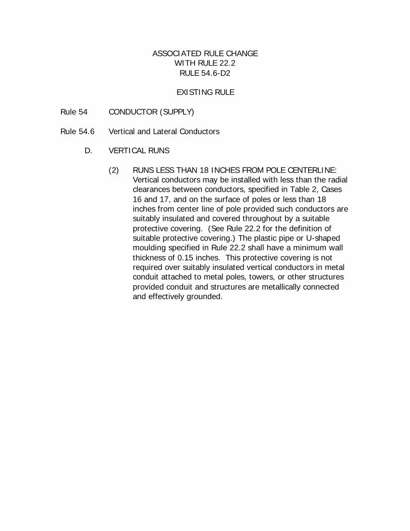
ASSOCIATED RULE CHANGE WITH RULE 22.2 RULE 54.6-D2
EXISTING RULE
Rule 54 CONDUCTOR (SUPPLY) Rule 54.6 Vertical and Lateral Conductors
D. VERTICAL RUNS
(2) RUNS LESS THAN 18 INCHES FROM POLE CENTERLINE: Vertical conductors may be installed with less than the radial clearances between conductors, specified in Table 2, Cases 16 and 17, and on the surface of poles or less than 18 inches from center line of pole provided such conductors are suitably insulated and covered throughout by a suitable protective covering. (See Rule 22.2 for the definition of suitable protective covering.) The plastic pipe or U-shaped moulding specified in Rule 22.2 shall have a minimum wall thickness of 0.15 inches. This protective covering is not required over suitably insulated vertical conductors in metal conduit attached to metal poles, towers, or other structures provided conduit and structures are metallically connected and effectively grounded.
PROPOSED RULE CHANGE (STRIKE OUT AND UNDERLINED)
Rule 54 CONDUCTOR (SUPPLY) Rule 54.6 Vertical and Lateral Conductors
D. VERTICAL RUNS
(2) RUNS LESS THAN 18 INCHES FROM POLE CENTERLINE: Vertical conductors may be installed with less than the radial clearances between conductors, specified in Table 2, Cases 16 and 17, and on the surface of poles or less than 18 inches from center line of pole provided such conductors are suitably insulated and covered throughout by a suitable protective covering. (See Rule 22.2 for the definition of suitable protective covering.) The plastic pipe or U-shaped moulding specified in Rule 22.2 shall have a minimum wall thickness of 0.15 inches. This protective covering is not required over suitably insulated vertical conductors in metal conduit attached to metal poles, towers, or other structures provided conduit and structures are metallically connected and effectively grounded.
PROPOSED RULE CHANGE (FINAL)
Rule 54 CONDUCTOR (SUPPLY) Rule 54.6 Vertical and Lateral Conductors
D. VERTICAL RUNS
(2) RUNS LESS THAN 18 INCHES FROM POLE CENTERLINE: Vertical conductors may be installed with less than the radial clearances between conductors, specified in Table 2, Cases 16 and 17, and on the surface of poles or less than 18 inches from center line of pole provided such conductors are suitably insulated and covered throughout by a suitable protective covering. (See Rule 22.2 for the definition of suitable protective covering.) This protective covering is not required over suitably insulated vertical conductors in metal conduit attached to metal poles, towers, or other structures provided conduit and structures are metallically connected and effectively grounded.
ASSOCIATED RULE CHANGE WITH RULE 22.2 RULE 54.6-D2
EXISTING RULE
Rule 54 CONDUCTOR (SUPPLY) Rule 54.6 Vertical and Lateral Conductors
D. VERTICAL RUNS
(3) RUNS 18 INCHES FROM POLE CENTERLINE: Vertical conductors may be installed with less than the radial clearances between conductors, specified in Table 2, Cases 16 and 17, and at a distance of more than 18 inches from the center line of any pole provided that such conductors are suitably insulated and covered by suitable protective covering or by securely supported impregnated fiber conduit without metal conduit. Such conductors shall be located outside of the climbing and working spaces and shall not pass between conductors of different ownership except between the pole pair and at a clearance therefrom of no less than 6 inches.
PROPOSED RULE CHANGE (STRIKE OUT AND UNDERLINED)
Rule 54 CONDUCTOR (SUPPLY) Rule 54.6 Vertical and Lateral Conductors
D. VERTICAL RUNS
(3) RUNS 18 INCHES FROM POLE CENTERLINE: Vertical conductors may be installed with less than the radial clearances between conductors, specified in Table 2, Cases 16 and 17, and at a distance of more than 18 inches from the center line of any pole provided that such conductors are suitably insulated and covered by suitable protective covering or by securely supported impregnated fiber conduit without metal conduit. Such conductors shall be located outside of the climbing and working spaces and shall not pass between conductors of different ownership except between the pole pair and at a clearance therefrom of no less than 6 inches.
PROPOSED RULE CHANGE (FINAL)
Rule 54 CONDUCTOR (SUPPLY) Rule 54.6 Vertical and Lateral Conductors
D. VERTICAL RUNS
(3) RUNS 18 INCHES FROM POLE CENTERLINE: Vertical conductors may be installed with less than the radial clearances between conductors, specified in Table 2, Cases 16 and 17, and at a distance of more than 18 inches from the center line of any pole provided that such conductors are suitably insulated and covered by suitable protective covering. Such conductors shall be located outside of the climbing and working spaces and shall not pass between conductors of different ownership except between the pole pair and at a clearance therefrom of no less than 6 inches.
ASSOCIATED RULE CHANGE With Rule 22.2 Rule 54.7-A3
EXISTING RULE
Rule 54 CONDUCTORS (SUPPLY) Rule 54.7 Climbing and Working Space
A. CLIMBING SPACE
3 Allowable Climbing Space Obstructions:
Crossarms and their supporting members are allowed in climbing spaces. Insulators and their attaching brackets which support line conductors may extend not more than one-half of their diameter into the climbing space.
Suitably protected vertical conductors attached to the surfaces of poles, and guys, (except those guys contacting metal pins or dead-end hardware as specified in Rule 52.7-D) are allowed in climbing spaces provided that not more than two guys (provided they are separated at the pole by a vertical distance of not more than 18 inches) and one vertical riser, run, or ground wire are installed in any 4-foot vertical section of climbing space.
Bolts bonded to or used for the attachment of dead-end hardware of a circuit of any voltage in horizontal (wood crossarm) configuration may project into the climbing space provided they are covered with non-conducting material as specified in Rule 22.2-F. If such bolts are bonded, a positive electrical contact shall be made.
The covering of bolts required by this rule shall not apply to:
(a) Bolts associated with circuits of 0 to 750 volts at any
level on pole or structure.
(b) Bolts associated with circuits of more than 7500 volts when located at the top level of a pole.
Modifications of these requirements for rack construction are specified in Rule 54.9-F; for switches in Rule 58.5-D: and for climbing space without wood crossarms in Rule 54.11-G.
PROPOSED RULE CHANGE (STRIKE OUT AND UNDERLINED)
Rule 54 CONDUCTORS (SUPPLY) Rule 54.7 Climbing and Working Space
A. CLIMBING SPACE
3 Allowable Climbing Space Obstructions:
Crossarms and their supporting members are allowed in climbing spaces. Insulators and their attaching brackets which support line conductors may extend not more than one-half of their diameter into the climbing space.
Suitably protected vertical conductors attached to the surfaces of poles, and guys, (except those guys contacting metal pins or dead-end hardware as specified in Rule 52.7-D) are allowed in climbing spaces provided that not more than two guys (provided they are separated at the pole by a vertical distance of not more than 18 inches) and one vertical riser, run, or ground wire are installed in any 4-foot vertical section of climbing space.
Bolts bonded to or used for the attachment of dead-end hardware of a circuit of any voltage in horizontal (wood crossarm) configuration may project into the climbing space provided they are covered with non-conducting material as specified in Rule 22.2-F. If such bolts are bonded, a positive electrical contact shall be made.
The covering of bolts required by this rule shall not apply to:
(a) Bolts associated with circuits of 0 to 750 volts at any
level on pole or structure.
(b) Bolts associated with circuits of more than 7500 volts when located at the top level of a pole.
(c) Bolts associated with brackets and non–wood
crossarms.
Modifications of these requirements are specified in: Rule 54.9-F for rack construction are specified in Rule 54.9-F; for switches in Rule 58.5-D for switches: and Rule 54.11-G for climbing space without wood crossarms in Rule 54.11-G.
PROPOSED RULE CHANGE (FINAL)
Rule 54 CONDUCTORS (SUPPLY) Rule 54.7 Climbing and Working Space
A. CLIMBING SPACE
3 Allowable Climbing Space Obstructions:
Crossarms and their supporting members are allowed in climbing spaces. Insulators and their attaching brackets which support line conductors may extend not more than one-half of their diameter into the climbing space.
Suitably protected vertical conductors attached to the surfaces of poles, and guys, (except those guys contacting metal pins or dead-end hardware as specified in Rule 52.7-D) are allowed in climbing spaces provided that not more than two guys (provided they are separated at the pole by a vertical distance of not more than 18 inches) and one vertical riser, run, or ground wire are installed in any 4-foot vertical section of climbing space.
Bolts bonded to or used for the attachment of dead-end hardware of a circuit of any voltage in horizontal (wood crossarm) configuration may project into the climbing space provided they are covered with non-conducting material as specified in Rule 22.2-F. If such bolts are bonded, a positive electrical contact shall be made.
The covering of bolts required by this rule shall not apply to:
(a) Bolts associated with circuits of 0 to 750 volts at any
level on pole or structure.
(b) Bolts associated with circuits of more than 7500 volts when located at the top level of a pole.
(c) Bolts associated with brackets and non–wood
crossarms.
Modifications of these requirements are specified in: Rule 54.9-F for rack construction; for switches in Rule 58.5-D for switches: and Rule 54.11-G for climbing space without wood crossarms.
Ground wires, other than lightning protection wires not attached to equipment or ground wires on grounded structures, shall be covered by metal pipe or suitable covering of wood or metal or of plastic pipe material specified in Rule 22.2-C, for a distance above ground sufficient to protect against mechanical injury, but in no case shall such distance be less than 7 feet. Such covering may be omitted providing the ground wire in this 7-foot section has a mechanical strength at least equal to the strength of No.6 AWG medium-hard-drawn copper.
Portions of ground wires which are on the surface of wood poles and within 6 feet vertically of unprotected supply conductors supported on the same pole, shall be covered with a suitable protective covering (see Rule 22.2).
Ground wires, other than lightning protection wires not attached to equipment or ground wires on grounded structures, shall be covered by metal pipe or suitable covering of wood or metal or of plastic pipe conduit material specified in Rule 22.2-CB, for a distance above ground sufficient to protect against mechanical injury, but in no case shall such distance be less than 7 feet. Such covering may be omitted providing the ground wire in this 7-foot section has a mechanical strength at least equal to the strength of No.6 AWG medium-hard-drawn copper.
Portions of ground wires which are on the surface of wood poles and within 6 feet vertically of unprotected supply conductors supported on the same pole, shall be covered with a suitable protective covering (see Rule 22.2).
Ground wires, other than lightning protection wires not attached to equipment or ground wires on grounded structures, shall be covered by metal pipe or suitable covering of wood or metal or of plastic conduit material specified in Rule 22.2-B, for a distance above ground sufficient to protect against mechanical injury, but in no case shall such distance be less than 7 feet. Such covering may be omitted providing the ground wire in this 7-foot section has a mechanical strength at least equal to the strength of No.6 AWG medium-hard-drawn copper.
Portions of ground wires which are on the surface of wood poles and within 6 feet vertically of unprotected supply conductors supported on the same pole, shall be covered with a suitable protective covering (see Rule 22.2).
ASSOCIATED RULE CHANGE With Rule 22.2 Rule 84.6-D
EXISTING RULE
Rule 84 CONDUCTORS (COMMUNICATION) 84.6 Vertical and Lateral Conductors
D Vertical Runs
Vertical runs of communication wires or cables supported on the surface of wood poles or structures, shall be covered by a suitable protective covering (see Rule 22.2) where within a vertical distance of 3 feet above or 6 feet below unprotected supply conductors supported on the same pole or structure. Vertical runs of communication wires or cables on the surface of a wood pole shall be covered by a suitable protective covering where within a 6-foot radius of any other pole supporting supply conductors except that those portions of such runs which are more than 3 feet above or 6 feet below the level of unprotected supply conductors need not be covered. The plastic pipe specified in Rule 22.2-C shall have a minimum wall thickness of 0.15 inches. Cable and drop wire runs to or from terminal boxes are excepted from these requirements for covering, under the following conditions:
Where guard arms are installed above messengers or longitudinal cables which are less than 6 feet below but not less than 4 feet below unprotected supply conductors of 0-750 volts, or where cables are supported on crossarms at not less than 15 inches from center line of pole, in which cases any portion of metal sheathed cable runs on the surface of pole below the guard arm and in the same quadrant as the longitudinal cable (see App. G, Fig. 87), or below and on the same side of the pole with a crossarm which supports a longitudinal cable, need not be covered. Runs of bridled conductors, attached to surface of pole, need not be covered provided such runs are below the guard arm and in the same quadrant as the longitudinal cable, or where such runs are below and on the same side of pole with a cable arm and are not in the climbing space,
or are connected to service drops which are placed in accordance with the provisions of Rule 84.8-B2b .
Where bridled runs are not required to be covered by these rules, they shall be supported by bridle hooks or rings spaced at intervals of not more than 24 inches. Vertical runs shall be treated as risers (see Rule 84.6-E ) where within a distance of 8 feet from the ground line. Runs which terminate in the top of enclosures which afford ample mechanical protection to the runs may extend within 8 feet of the ground but not less than 6 feet of the ground without being treated as risers.
PROPOSED RULE CHANGE (STRIKE OUT AND UNDERLINED)
Rule 84 CONDUCTORS (COMMUNICATION) 84.6 Vertical and Lateral Conductors
D Vertical Runs
Vertical runs of communication wires or cables supported on the surface of wood poles or structures, shall be covered by a suitable protective covering (see Rule 22.2) where within a vertical distance of 3 feet above or 6 feet below unprotected supply conductors supported on the same pole or structure. Vertical runs of communication wires or cables on the surface of a wood pole shall be covered by a suitable protective covering where within a 6-foot radius of any other pole supporting supply conductors except that those portions of such runs which are more than 3 feet above or 6 feet below the level of unprotected supply conductors need not be covered. The plastic pipe specified in Rule 22.2-C shall have a minimum wall thickness of 0.15 inches. Cable and drop wire runs to or from terminal boxes are excepted exempted from these requirements for covering, under the following conditions:
Where guard arms are installed above messengers or longitudinal cables which are less than 6 feet below but not less than 4 feet below unprotected supply conductors of 0-750 volts, or where cables are supported on crossarms at not less than 15 inches from center line of pole, in which cases any portion of metal sheathed cable runs on the surface of pole below the guard arm and in the same quadrant as the longitudinal cable (see App. G, Fig. 87), or below and on the same side of the pole with a crossarm which supports a longitudinal cable, need not be covered. Runs of bridled conductors, attached to surface of pole, need not be covered provided such runs are below the guard arm and in the same quadrant as the longitudinal cable, or where such runs are below and on the same side of pole with a cable arm and are not in the climbing space, or are connected to service drops which are placed in accordance with the provisions of Rule 84.8-B2b .
Where bridled runs are not required to be covered by these rules, they shall be supported by bridle hooks or rings spaced at intervals of not more than 24 inches. Vertical runs shall be treated as risers (see Rule 84.6-E ) where within a distance of 8 feet from the ground line. Runs which terminate in the top of enclosures which afford ample mechanical protection to the runs may extend within 8 feet of the ground but not less than 6 feet of the ground without being treated as risers.
PROPOSED RULE CHANGE (FINAL)
Rule 84 CONDUCTORS (COMMUNICATION) 84.6 Vertical and Lateral Conductors
D Vertical Runs
Vertical runs of communication wires or cables supported on the surface of wood poles or structures, shall be covered by a suitable protective covering (see Rule 22.2) where within a vertical distance of 3 feet above or 6 feet below unprotected supply conductors supported on the same pole or structure. Vertical runs of communication wires or cables on the surface of a wood pole shall be covered by a suitable protective covering where within a 6-foot radius of any other pole supporting supply conductors except that those portions of such runs which are more than 3 feet above or 6 feet below the level of unprotected supply conductors need not be covered. Cable and drop wire runs to or from terminal boxes are exempted from these requirements for covering, under the following conditions:
Where guard arms are installed above messengers or longitudinal cables which are less than 6 feet below but not less than 4 feet below unprotected supply conductors of 0-750 volts, or where cables are supported on crossarms at not less than 15 inches from center line of pole, in which cases any portion of metal sheathed cable runs on the surface of pole below the guard arm and in the same quadrant as the longitudinal cable (see App. G, Fig. 87), or below and on the same side of the pole with a crossarm which supports a longitudinal cable, need not be covered. Runs of bridled conductors, attached to surface of pole, need not be covered provided such runs are below the guard arm and in the same quadrant as the longitudinal cable, or where such runs are below and on the same side of pole with a cable arm and are not in the climbing space, or are connected to service drops which are placed in accordance with the provisions of Rule 84.8-B2b .
Where bridled runs are not required to be covered by these rules, they shall be supported by bridle hooks or rings spaced at intervals
of not more than 24 inches. Vertical runs shall be treated as risers (see Rule 84.6-E ) where within a distance of 8 feet from the ground line. Runs which terminate in the top of enclosures which afford ample mechanical protection to the runs may extend within 8 feet of the ground but not less than 6 feet of the ground without being treated as risers.
SUMMARY OF ASSOCIATED RULE CHANGES TO RULE 22.2
Rule 22.2 Protective Covering, Suitable Note: With reference to deleting existing Rule 22.2-A (Definition of Impregnated Fiber Conduit). Rule 54.6-C2 was revised by Resolution No. SU-5 and the reference to impregnated fiber conduit was deleted because it is no longer used in the industry. 1. Appendix G, Fig. 83: Delete entire figure 2. Rule 20.8-E: Delete – “or impregnated fiber” 3. Rule 54.6-C2: a) Change - plastic pipe to read “plastic conduit” b) Change - reference to Rule 22.2-C; to “Rule 22.2-B” 4. Rule 54.6-C3: a) Delete - “impregnated fiber conduit or” b) Change - plastic pipe to read “plastic conduit” c) Delete - “or pipe” (“after such conduit”) 5. Rule 54.6-D2: Delete the sentence – “The plastic pipe or U-shaped
moulding specified in Rule 22.2 shall be a minimum wall thickness of o.15 inches.”
6. Rule 54.6-D2: “or by securely supported impregnated fiber conduit without metal conduit”
7. Rule 54.7-A3: Delete - the comma (,) after reference to Rule 52.7-D Change - reference to Rule 22.2-F; to read “Rule
22.2-C” Add - c. Bolts associated with brackets and non–
wood crossarms. Change - Last Paragraph to read: “Modifications
of these requirements are specified in: Rule 54.9-F for rack construction; for switches in Rule 58.5-D for switches: and Rule 54.11-G for climbing space without wood crossarms.”
8. Rule 84.6-B: Change - a) plastic pipe; to read “plastic conduit” b) Rule 22.2-C; to read Rule 22.2-A 9. Rule 84.6-D: Delete – the sentence; ” The plastic pipe specified in Rule
22.2-C shall have a minimum wall thickness of 0.15 inches.” (Located in the first paragraph) Change – excepted to “exempted” (last sentence, first paragraph)
RATIONALE FOR PROPOSED RULE CHANGES RULES 23.1 and 23.1-A
TERMINAL and TERMINAL FITTINGS RULES 23.2 and 23.2-A
TERMINATION and TERMINATION APPARATUS
(Delete Rule 20.8-H)
The proposed changes will add definition for Terminal, Terminal Fittings, Termination and Termination Apparatus. This will provide clarity to proposed changes to Rules 54.6-F and 54.6-G.
EXISTING RULE (Rule 20.8-H)
TERMINAL FITTINGS (New Rule 23.1)
Rule 20.8 Conductor (Definition) Rule 20.8-H H Terminal Fittings are the terminal equipment used in terminating the
conductors of runs and risers and include cable potheads and conduit entrance fittings.
PROPOSE DRULE CHANGE
(STRIKE OUT AND UNDERLINED) (Existing Rule 20.8-H) TERMINAL FITTINGS
(New Rule 23.1) TERMINAL and TERMINAL FITTINGS
Rule 20.8-H H Terminal Fittings are the terminal equipment used in terminating the
conductors of runs and risers and include cable potheads and conduit entrance fittings.
23.1 Terminal means a position in an electric circuit or device at which an
electric connection is normally established or broken. This is the point at which current enters or leaves a conducting element in a circuit. A terminal is normally energized and its associated parts may be energized, non–energized, grounded, or non–grounded. A. Terminal Fittings (normally used in conjunction with lead
risers) are the terminal equipment used in terminating the conductors of runs and risers (e.g. transition of three conductor lead to three single conductors or terminals, cable to potheads, etc.), and include cable potheads, weather heads, and conduit entrance fittings.
PROPOSED RULE CHANGE (FINAL)
Rule 23.1 TERMINAL and TERMINAL FITTINGS
(Definitions) 23.1 Terminal means a position in an electric circuit or device at which an
electric connection is normally established or broken. This is the point at which current enters or leaves a conducting element in a circuit. A terminal is normally energized and its associated parts may be energized, non–energized, grounded, or non–grounded. A. Terminal Fittings (normally used in conjunction with lead risers) are
the terminal equipment used in terminating the conductors of runs and risers (e.g. transition of three conductor lead to three single conductors or terminals, cable to potheads, etc.), and include cable potheads, weather heads, and conduit entrance fittings.
PROPOSED NEW RULE (FINAL)
Rule 23.2 TERMINATION and TERMINATION APPARATUS
(Definitions) Rule 23.2 23.2 Termination means the end of something or point where it ends, such
as where the conductor or underground riser cable ends at the termination apparatus.
A. Termination Apparatus (normally used in conjunction
with non–lead risers) is the equipment or parts of equipment that is used to terminate riser cables. This equipment can be grounded, non–grounded, energized, or non–energized. This equipment and its associated parts include, but is not limited to, stress cones (heat–shrink, cold–shrink, taped, etc.), potheads, various types of terminals and terminal fittings, and various types of bushings.
ASSOCIATED RULE CHANGES Renumber Existing Rules 23.1, 23.2, 23.3, and 23.4 to 23.3, 23.4, 23.5 and 23.6 respectively 23.1 23.3 Thoroughfares 23.2 23.4 Voltage (or Volts) 23.3 23.5 Wire Guys 23.4 23.6 Working Space
RATIONALE FOR PROPOSED RULE CHANGE RULE 33.2
(GENERAL ORDER 95) The proposed rule change will further clarify the rule by specifically stating that ground or earth shall not be used as a normal return or circuit conductor. Also, the existing text was rearranged for additional clarity.
EXISITING RULE RULE 33.2
(GENERAL ORDER 95) 33.2 Ground or Earth as a Conductor
The Grounding of the neutral or any other conductor in direct current supply systems or in single phase poly-phase supply systems is permitted only for the purposes of stabilization and protection, and not for use as a return conductor.
PROPOSED RULE CHANGE
(STRIKE OUT AND UNDERLINED) RULE 33.2
(GENERAL ORDER 95) 33.2 Ground or Earth as a Conductor
Ground or earth shall not be used as a normal return or circuit conductor. In direct current supply systems or in single phase or polyphase supply systems, a The Grounding of the neutral or any other conductor shall be used under normal use as a return or circuit conductor; however, the grounding of the neutral or any other conductor in direct current supply systems or in single phase poly-phase supply systems is not permitted as a normal return or circuit only for the purposes of stabilization and protection, and not for use as a return conductor. The neutral or any other conductor is permitted to be grounded only for the purposes of stabilization and protection.
PROPOSED RULE CHANGE
(FINAL) RULE 33.2
(GENERAL ORDER 95) 33.2 Ground or Earth as a Conductor
Ground or earth shall not be used as a normal return or circuit conductor. In direct current supply systems or in single phase or polyphase supply systems, a neutral or any other conductor shall be used under normal use as a return or circuit conductor; however, the grounding of the neutral or any other is not permitted as a normal return or circuit conductor. The neutral or any other conductor is permitted to be grounded only for the purposes of stabilization and protection.
RATIONALE FOR PROPOSED RULE CHANGE TABLE 2 CASE 18
And ASSOCIATED RULE CHANGE
Fig. 56-1 (Rule 56.4-C3 Guys Approximately Parallel)
The proposed rule change will require the same clearance for guys passing conductors supported on other poles and guys approximately parallel to conductors supported on the same pole as the clearance required between conductors on the same crossarm. Changing these clearances will allow a guy, as shown in Fig. 56-1, to be attached directly behind the conductor that it is supporting while maintaining the same safety as is provided in Table 2, Case 15, conductors from other conductors.
Existing Rule Table 2
Basic Minimum Allowable Clearance of Wires from Other Wires at Crossings, in Midspans and at Supports (Letter references Denote Modifications of Minimum Clearances Referred to in Notes Following this Table)
All Clearances Are in Inches Other Wire, cable or conductor concerned
Supply conductor (including supply cables)
Case No.
Nature of Clearance and Class of Voltage of wire, cable or
conductor concerned
A Span wires, guys and
messengers
B Trolley contact conductors 0-750 volts
C Communication
conductors (including open wire, cables and service drops)
D 0-750 volts (including
service drops and trolley
feeders (a) )
E 750-
7,500 Volts
F 7,500-20,000 volts
G 20,000-35,000 volts
H 35,000-75,000 volts
I 75,000-150,000
volts
J 150,000
-300,000
volts
K 300,000
-550,000
volts
Clearance between wires, cables, and conductors not supported on the same poles, vertically at crossings in spans, and radially where collinear or approaching crossing
Vertical separation between conductors and / or cables on separate crossarms or other supports at different levels (excepting on related line and buck arms on the same pole and in adjoining
same pole and in adjoining Midspans)
8 Communication conductors and service drops
-------------
-------------
12 (j) 48 (k, l, m, n, pp)
48 (k) 72 (m, n) 72(m) 72 78 87 (gg) 147(hh)
9 Supply Conductors, service drops and trolley feeders 0-750 volts
-------------
-------------
48 (k, l, m, n, pp)
24 (h, k, m, o)
48 (k, m, p)
48 (k, m, q)
72(m) (nn)
72 78 87 (gg) 147(hh)
10 Supply conductors, 750-7500 volts
-------------
-------------
48 (k) 48 (k, m, p) 48 (m, o, r, ee)
48 (m, q) 48(q) 48(q) 60(ff) 90 (gg) 150(hh)
11 Supply conductors 7500-20,000 volts
-------------
-------------
72 (m, n) 48 (k, m, q) 48 (m, q)
48 (m, o, q, r, ee)
48(q) 48(q) 60(ff) 90 (gg) 150(hh)
12 Supply conductors 20,000-68,000 75,000 volts
-------------
-------------
72 (m) 72 (m) 48 (m, q)
48 (m, q) 48(o, q)
48(o, q)
60(ff) 90 (gg) 150(hh)
13 Supply conductors, more than 68,000 75,000 volts
Horizontal separation of conductors on same crossarm
15 Pin spacings of longitudinal conductors, vertical conductors and service drops (v, w)
-------------
-------------
3(x) 11 ½ (h, x) 11 ½ (x)
17 ½ (x) 24 (x) 48 60(ff) 90 (gg) 150(hh)
Radial separation of conductors on same crossarm, pole or structure Incidental pole wiring
16 Conductors, tap or lead wires of different circuits (v, y, z)
-------------
-------------
3 (x) 11 ½ (h, x) 11 ½ (x)
17 ½ (x) 24 (x) 48 60(ff) 90 (gg) 150(hh)
17 Conductors, tap or lead wires of same circuits (v, z, aa)
-------------
-------------
3 3 6 6 12 24 60(ff) 90 (gg) 150(hh)
Radial separation between guys and conductors
-------------
18 Guys passing conductors supported on other poles (excluding poles of same circuit), and guys approximately parallel to conductors supported on the
-------------
-------------
3 (bb) 12 18 18 30 36 36 (ff) 78 (gg) 138(hh)
same poles 19 Guys and spans wires passing
conductors supported on the same poles
(ee) (bb) 3 3 6 9 12 18 24 48 (ll) 86 (jj)
Vertical and Horizontal insulator-Vertical clearance between conductors
20 Vertical Clearance between conductors of the same circuit on Horizontal post insulators
- - - - 24 24 30 36 or 48 (ii) (mm)
48 (mm) 48(mm)
48(mm)
(a) The clearances in Column D are also applicable to supply cables of any voltage under certain conditions
57.4
(b) Clearances for guys and span wires apply vertically at crossings; see Case 18 for radial clearances from conductors.
1. Supply guys and span wires from conductors 2. Supply guys and span wires from guys and span wires 3. Communication guys and span wires from conductors 4. Communication guys and span wires from guys and span wires
56.4-C 56.4-D1 86.4-C 86.4-D1
(c) Not applicable between messengers or span wires of the same system.
1. Supply messengers 2. Trolley span wires 3. Communication messengers
57.4-E 77.4-D 87.4-G
(d) Protection required on guys, span wires, messengers, and cables where within trolley throw
1. Supply Guys and Span wires 2. Supply Messengers and Cables 3. Communication guys and span wires 4. Communication messengers
56.4-B2 57.4-B2 86.4-B2 87.4-B2
(e) Not applicable to certain conductors supported on trolley span wires.
1. Trolley contact and feeder conductors 2. Trolley feeder conductors 3. Trolley system communication conductors 4. Foreign conductors
74.4-G 78.1 78.2 78.3
(f) Increased clearance required over trolley contact conductors of 750-7500 volts
74.4-G2
(g) Shall be increased for conductors of more than 75,000 volts. As required by Table 2 Columns I, J, and K
(h) May be reduced for certain conductors of Class T circuits of the same system
74.4-C
(i) May be reduced for service drops under special conditions.
1. Supply service drops and communication line conductors 2. Supply service drops and communication service drops 3. Communication service drops and supply line conductors 4. Communication service drops and supply service drops
54.8-C1a 54.8-C4 84.8-D1a 84.8-D4
(j) May be reduced or shall be increased for certain communication conductors or cables.
1. Open wire conductors, attached to poles, within 3 feet of topmost conductor
2. Line conductors of police or fire-alarm circuits and service drops from other communication circuits.
3. Cables and messengers attached to poles
84.4-C1a 84.8-D1b 87.4-C3
(k) Special clearances for 0-750 volt conductors in rack configuration and messengers and cables attached to poles.
1. Supply conductors of 0-750 volts in rack configuration 2. Supply cables and messengers attached to poles 3. Communication cables and messengers attached to poles 4. On Jointly used poles
54.9 57.4-F 87.4-C3 92.1
(l) May be reduced for service drops, and police or fire-alarm conductors, under special conditions.
1. Supply service drops and communication line conductors
2. Supply service drops on clearance arms 3. Supply service drops on pole-top extensions 4. Supply service drops and communication service
drops 5. Communication service drops and police, fire-alarm
or supply line conductors 6. Communication service drops on clearance arms 7. Communication service drops on pole-top extensions 8. Communication service drops and supply service
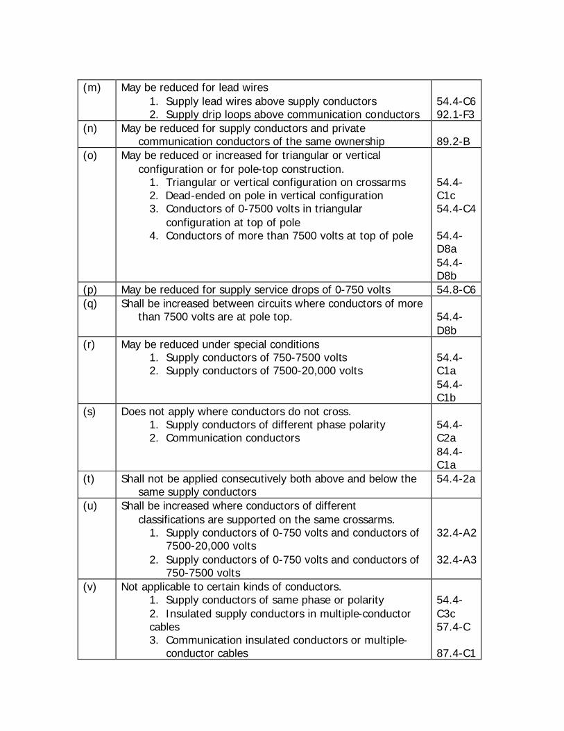
1. Supply lead wires above supply conductors 2. Supply drip loops above communication conductors
54.4-C6 92.1-F3
(n) May be reduced for supply conductors and private communication conductors of the same ownership
89.2-B
(o) May be reduced or increased for triangular or vertical configuration or for pole-top construction.
1. Triangular or vertical configuration on crossarms 2. Dead-ended on pole in vertical configuration 3. Conductors of 0-7500 volts in triangular
configuration at top of pole 4. Conductors of more than 7500 volts at top of pole
54.4-C1c 54.4-C4 54.4-D8a 54.4-D8b
(p) May be reduced for supply service drops of 0-750 volts 54.8-C6 (q) Shall be increased between circuits where conductors of more
than 7500 volts are at pole top. 54.4-D8b
(r) May be reduced under special conditions 1. Supply conductors of 750-7500 volts 2. Supply conductors of 7500-20,000 volts
54.4-C1a 54.4-C1b
(s) Does not apply where conductors do not cross. 1. Supply conductors of different phase polarity 2. Communication conductors
54.4-C2a 84.4-C1a
(t) Shall not be applied consecutively both above and below the same supply conductors
54.4-2a
(u) Shall be increased where conductors of different classifications are supported on the same crossarms.
1. Supply conductors of 0-750 volts and conductors of 7500-20,000 volts
2. Supply conductors of 0-750 volts and conductors of 750-7500 volts
32.4-A2 32.4-A3
(v) Not applicable to certain kinds of conductors. 1. Supply conductors of same phase or polarity 2. Insulated supply conductors in multiple-conductor cables 3. Communication insulated conductors or multiple-
conductor cables
54.4-C3c 57.4-C 87.4-C1
(w) Shall apply radially to conductors on brackets attached to crossarms. 1. Supply conductors 2. Communication conductors
54.4-C3b 84.8-C1b
(x) Shall be increased between conductors of different classifications supported on the same crossarm.
1. Supply conductors of different voltage classification 2. Supply circuits of 0-750 volts and communication circuits 3. Supply circuits and private communication circuits.
32.4-A 32.4-B 89.2-A
(y) Special clearances for unprotected supply conductors from one level to another level
54.6-A 58.2-B3 92.1-F5
(z) Not applicable to the following: 1. Clearances between conductors at different levels
specified in Cases 8 to 13 inclusive. 2. Supply lateral conductors, suitably protected 3. Supply vertical runs, suitably protected 4. Supply risers, suitably protected 5. Communication Conductors
54.6-C 54.6-D 54.6-E 87.4-C1
(aa) Not applicable between cables and their supporting messengers.
1. Supply 2. Communication
57.4-D 87.4-F
(bb) May be reduced for communication guys and communication conductors supported on the same poles
1. Supply 2. Communication
56.4-C4 86.4-C
(cc) Clearance required between guys. 1. Supply guys, crossing 2. Supply guys, approximately parallel 3. Communication guys, crossing 4. Communication guys, approximately parallel
56.4-D2 56.4-D3 86.4-D2 86.4-D3
(dd) Shall be increased where within 6 feet of a pole 103.5 (ee) May be decreased in partial underground distribution 54.4-
C4c (ff) shall be increased by 0.40 inches per kV in excess of 75 kV (gg) shall be increased by 0.40 inches per kV in excess of 150 kV (hh) shall be increased by 0.40 inches per kV in excess of 300 kV (ii) shall be increased by 0.25 inches per kV in excess of 150 kV
(jj) shall be increased by 0.25 inches per kV in excess of 300 kV (kk) proposed clearances to submitted to the CPUC prior to
construction for circuits in excess of 550 kV
(ll) 36-inch clearance applies 35 kV to 68kV 48-inch clearance applies over 68 kV
(mm) vertical clearance shall be increased by ½ inch for each kilovolt over 68 kV
(nn) The vertical separation between supply conductors and service drops Of 0-750 volts and 20,000-22,500-volt conductors may be reduced to 48 inches.
(oo) May be reduced to 72 inches for conductors of 20,000-22,500 volts.
(pp) May be reduced to 36 inches vertically at midspan only when the supply conductors consist of abrasion resistant cable with a grounded metallic sheath or neutral–supported cable as specified in Rules 57 and 54.10 .
(qq) Vertical clearances may be reduced between supply conductors of the same circuit at crossings in spans
54.4–C7
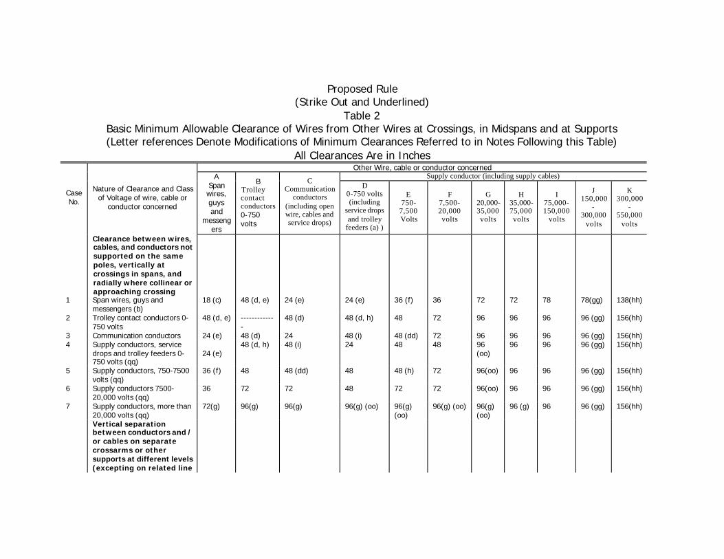
Proposed Rule (Strike Out and Underlined)
Table 2 Basic Minimum Allowable Clearance of Wires from Other Wires at Crossings, in Midspans and at Supports (Letter references Denote Modifications of Minimum Clearances Referred to in Notes Following this Table)
All Clearances Are in Inches Other Wire, cable or conductor concerned
Supply conductor (including supply cables)
Case No.
Nature of Clearance and Class of Voltage of wire, cable or
conductor concerned
A Span wires, guys and
messengers
B Trolley contact conductors 0-750 volts
C Communication
conductors (including open wire, cables and service drops)
D 0-750 volts (including
service drops and trolley
feeders (a) )
E 750-
7,500 Volts
F 7,500-20,000 volts
G 20,000-35,000 volts
H 35,000-75,000 volts
I 75,000-150,000
volts
J 150,000
-300,000
volts
K 300,000
-550,000
volts
Clearance between wires, cables, and conductors not supported on the same poles, vertically at crossings in spans, and radially where collinear or approaching crossing
Vertical separation between conductors and / or cables on separate crossarms or other supports at different levels (excepting on related line and buck arms on the
and buck arms on the same pole and in adjoining Midspans)
8 Communication conductors and service drops
-------------
-------------
12 (j) 48 (k, l, m, n, pp)
48 (k) 72 (m, n) 72(m) 72 78 87 (gg) 147(hh)
9 Supply Conductors, service drops and trolley feeders 0-750 volts
-------------
-------------
48 (k, l, m, n, pp)
24 (h, k, m, o)
48 (k, m, p)
48 (k, m, q)
72(m) (nn)
72 78 87 (gg) 147(hh)
10 Supply conductors, 750-7500 volts
-------------
-------------
48 (k) 48 (k, m, p) 48 (m, o, r, ee)
48 (m, q) 48(q) 48(q) 60(ff) 90 (gg) 150(hh)
11 Supply conductors 7500-20,000 volts
-------------
-------------
72 (m, n) 48 (k, m, q) 48 (m, q)
48 (m, o, q, r, ee)
48(q) 48(q) 60(ff) 90 (gg) 150(hh)
12 Supply conductors 20,000-68,000 75,000 volts
-------------
-------------
72 (m) 72 (m) 48 (m, q)
48 (m, q) 48(o, q)
48(o, q)
60(ff) 90 (gg) 150(hh)
13 Supply conductors, more than 68,000 75,000 volts
Horizontal separation of conductors on same crossarm
15 Pin spacings of longitudinal conductors, vertical conductors and service drops (v, w)
-------------
-------------
3(x) 11 ½ (h, x) 11 ½ (x)
17 ½ (x) 24 (x) 48 60(ff) 90 (gg) 150(hh)
Radial separation of conductors on same crossarm, pole or structure Incidental pole wiring
16 Conductors, tap or lead wires of different circuits (v, y, z)
-------------
-------------
3 (x) 11 ½ (h, x) 11 ½ (x)
17 ½ (x) 24 (x) 48 60(ff) 90 (gg) 150(hh)
17 Conductors, tap or lead wires of same circuits (v, z, aa)
-------------
-------------
3 3 6 6 12 24 60(ff) 90 (gg) 150(hh)
Radial separation between guys and conductors
-------------
18 Guys passing conductors supported on other poles (excluding poles of same circuit), and guys approximately parallel to
-------------
-------------
3 (bb) 12 11 ½
18 11 ½
18 17 ½
30 24
36 36 (ff) 78 (gg) 138(hh)
conductors supported on the same poles
19 Guys and spans wires passing conductors supported on the same poles
(ee) (bb) 3 3 6 9 12 18 24 48 (ll) 86 (jj)
Vertical and Horizontal insulator-Vertical clearance between conductors
20 Vertical Clearance between conductors of the same circuit on Horizontal post insulators
- - - - 24 24 30 36 or 48 (ii) (mm)
48 (mm) 48(mm)
48(mm)
(a) The clearances in Column D are also applicable to supply cables of any voltage under certain conditions
57.4
(b) Clearances for guys and span wires apply vertically at crossings; see Case 18 for radial clearances from conductors.
1. Supply guys and span wires from conductors 2. Supply guys and span wires from guys and span wires 3. Communication guys and span wires from conductors 4. Communication guys and span wires from guys and span wires
56.4-C 56.4-D1 86.4-C 86.4-D1
(c) Not applicable between messengers or span wires of the same system.
1. Supply messengers 2. Trolley span wires 3. Communication messengers
57.4-E 77.4-D 87.4-G
(d) Protection required on guys, span wires, messengers, and cables where within trolley throw
1. Supply Guys and Span wires 2. Supply Messengers and Cables 3. Communication guys and span wires 4. Communication messengers
56.4-B2 57.4-B2 86.4-B2 87.4-B2
(e) Not applicable to certain conductors supported on trolley span wires.
1. Trolley contact and feeder conductors 2. Trolley feeder conductors 3. Trolley system communication conductors 4. Foreign conductors
74.4-G 78.1 78.2 78.3
(f) Increased clearance required over trolley contact conductors of 750-7500 volts
74.4-G2
(g) Shall be increased for conductors of more than 75,000 volts. As required by Table 2 Columns I, J, and K
(h) May be reduced for certain conductors of Class T circuits of the same system
74.4-C
(i) May be reduced for service drops under special conditions.
1. Supply service drops and communication line conductors 2. Supply service drops and communication service drops 3. Communication service drops and supply line conductors 4. Communication service drops and supply service drops
54.8-C1a 54.8-C4 84.8-D1a 84.8-D4
(j) May be reduced or shall be increased for certain communication conductors or cables.
1. Open wire conductors, attached to poles, within 3 feet of topmost conductor
2. Line conductors of police or fire-alarm circuits and service drops from other communication circuits.
3. Cables and messengers attached to poles
84.4-C1a 84.8-D1b 87.4-C3
(k) Special clearances for 0-750 volt conductors in rack configuration and messengers and cables attached to poles.
1. Supply conductors of 0-750 volts in rack configuration 2. Supply cables and messengers attached to poles 3. Communication cables and messengers attached to poles 4. On Jointly used poles
54.9 57.4-F 87.4-C3 92.1
(l) May be reduced for service drops, and police or fire-alarm conductors, under special conditions.
1. Supply service drops and communication line conductors
2. Supply service drops on clearance arms 3. Supply service drops on pole-top extensions 4. Supply service drops and communication service
drops 5. Communication service drops and police, fire-alarm
or supply line conductors 6. Communication service drops on clearance arms 7. Communication service drops on pole-top extensions 8. Communication service drops and supply service
1. Supply lead wires above supply conductors 2. Supply drip loops above communication conductors
54.4-C6 92.1-F3
(n) May be reduced for supply conductors and private communication conductors of the same ownership
89.2-B
(o) May be reduced or increased for triangular or vertical configuration or for pole-top construction.
1. Triangular or vertical configuration on crossarms 2. Dead-ended on pole in vertical configuration 3. Conductors of 0-7500 volts in triangular
configuration at top of pole 4. Conductors of more than 7500 volts at top of pole
54.4-C1c 54.4-C4 54.4-D8a 54.4-D8b
(p) May be reduced for supply service drops of 0-750 volts 54.8-C6 (q) Shall be increased between circuits where conductors of more
than 7500 volts are at pole top. 54.4-D8b
(r) May be reduced under special conditions 1. Supply conductors of 750-7500 volts 2. Supply conductors of 7500-20,000 volts
54.4-C1a 54.4-C1b
(s) Does not apply where conductors do not cross. 1. Supply conductors of different phase polarity 2. Communication conductors
54.4-C2a 84.4-C1a
(t) Shall not be applied consecutively both above and below the same supply conductors
54.4-2a
(u) Shall be increased where conductors of different classifications are supported on the same crossarms.
1. Supply conductors of 0-750 volts and conductors of 7500-20,000 volts
2. Supply conductors of 0-750 volts and conductors of 750-7500 volts
32.4-A2 32.4-A3
(v) Not applicable to certain kinds of conductors. 1. Supply conductors of same phase or polarity 2. Insulated supply conductors in multiple-conductor cables 3. Communication insulated conductors or multiple-
conductor cables
54.4-C3c 57.4-C 87.4-C1
(w) Shall apply radially to conductors on brackets attached to crossarms. 1. Supply conductors 2. Communication conductors
54.4-C3b 84.8-C1b
(x) Shall be increased between conductors of different classifications supported on the same crossarm.
1. Supply conductors of different voltage classification 2. Supply circuits of 0-750 volts and communication circuits 3. Supply circuits and private communication circuits.
32.4-A 32.4-B 89.2-A
(y) Special clearances for unprotected supply conductors from one level to another level
54.6-A 58.2-B3 92.1-F5
(z) Not applicable to the following: 1. Clearances between conductors at different levels
specified in Cases 8 to 13 inclusive. 2. Supply lateral conductors, suitably protected 3. Supply vertical runs, suitably protected 4. Supply risers, suitably protected 5. Communication Conductors
54.6-C 54.6-D 54.6-E 87.4-C1
(aa) Not applicable between cables and their supporting messengers.
1. Supply 2. Communication
57.4-D 87.4-F
(bb) May be reduced for communication guys and communication conductors supported on the same poles
1. Supply 2. Communication
56.4-C4 86.4-C
(cc) Clearance required between guys. 1. Supply guys, crossing 2. Supply guys, approximately parallel 3. Communication guys, crossing 4. Communication guys, approximately parallel
56.4-D2 56.4-D3 86.4-D2 86.4-D3
(dd) Shall be increased where within 6 feet of a pole 103.5 (ee) May be decreased in partial underground distribution 54.4-
C4c (ff) shall be increased by 0.40 inches per kV in excess of 75 kV (gg) shall be increased by 0.40 inches per kV in excess of 150 kV (hh) shall be increased by 0.40 inches per kV in excess of 300 kV (ii) shall be increased by 0.25 inches per kV in excess of 150 kV
(jj) shall be increased by 0.25 inches per kV in excess of 300 kV (kk) proposed clearances to submitted to the CPUC prior to
construction for circuits in excess of 550 kV
(ll) 36-inch clearance applies 35 kV to 68kV 48-inch clearance applies over 68 kV
(mm) vertical clearance shall be increased by ½ inch for each kilovolt over 68 kV
(nn) The vertical separation between supply conductors and service drops Of 0-750 volts and 20,000-22,500-volt conductors may be reduced to 48 inches.
(oo) May be reduced to 72 inches for conductors of 20,000-22,500 volts.
(pp) May be reduced to 36 inches vertically at midspan only when the supply conductors consist of abrasion resistant cable with a grounded metallic sheath or neutral–supported cable as specified in Rules 57 and 54.10 .
(qq) Vertical clearances may be reduced between supply conductors of the same circuit at crossings in spans
54.4–C7
Proposed Rule (FINAL) Table 2
Basic Minimum Allowable Clearance of Wires from Other Wires at Crossings, in Midspans and at Supports (Letter references Denote Modifications of Minimum Clearances Referred to in Notes Following this Table)
All Clearances Are in Inches Other Wire, cable or conductor concerned
Supply conductor (including supply cables)
Case No.
Nature of Clearance and Class of Voltage of wire, cable or
conductor concerned
A Span wires, guys and
messengers
B Trolley contact conductors 0-750 volts
C Communication
conductors (including open wire, cables and service drops)
D 0-750 volts (including
service drops and trolley
feeders (a) )
E 750-
7,500 Volts
F 7,500-20,000 volts
G 20,000-35,000 volts
H 35,000-75,000 volts
I 75,000-150,000
volts
J 150,000
-300,000
volts
K 300,000
-550,000
volts
Clearance between wires, cables, and conductors not supported on the same poles, vertically at crossings in spans, and radially where collinear or approaching crossing
Vertical separation between conductors and / or cables on separate crossarms or other supports at different levels (excepting on related line and buck arms on the
and buck arms on the same pole and in adjoining Midspans)
8 Communication conductors and service drops
-------------
-------------
12 (j) 48 (k, l, m, n, pp)
48 (k) 72 (m, n) 72(m) 72 78 87 (gg) 147(hh)
9 Supply Conductors, service drops and trolley feeders 0-750 volts
-------------
-------------
48 (k, l, m, n, pp)
24 (h, k, m, o)
48 (k, m, p)
48 (k, m, q)
72(m) (nn)
72 78 87 (gg) 147(hh)
10 Supply conductors, 750-7500 volts
-------------
-------------
48 (k) 48 (k, m, p) 48 (m, o, r, ee)
48 (m, q) 48(q) 48(q) 60(ff) 90 (gg) 150(hh)
11 Supply conductors 7500-20,000 volts
-------------
-------------
72 (m, n) 48 (k, m, q) 48 (m, q)
48 (m, o, q, r, ee)
48(q) 48(q) 60(ff) 90 (gg) 150(hh)
12 Supply conductors 20,000-68,000 75,000 volts
-------------
-------------
72 (m) 72 (m) 48 (m, q)
48 (m, q) 48(o, q)
48(o, q)
60(ff) 90 (gg) 150(hh)
13 Supply conductors, more than 68,000 75,000 volts
Horizontal separation of conductors on same crossarm
15 Pin spacings of longitudinal conductors, vertical conductors and service drops (v, w)
-------------
-------------
3(x) 11 ½ (h, x) 11 ½ (x)
17 ½ (x) 24 (x) 48 60(ff) 90 (gg) 150(hh)
Radial separation of conductors on same crossarm, pole or structure Incidental pole wiring
16 Conductors, tap or lead wires of different circuits (v, y, z)
-------------
-------------
3 (x) 11 ½ (h, x) 11 ½ (x)
17 ½ (x) 24 (x) 48 60(ff) 90 (gg) 150(hh)
17 Conductors, tap or lead wires of same circuits (v, z, aa)
-------------
-------------
3 3 6 6 12 24 60(ff) 90 (gg) 150(hh)
Radial separation between guys and conductors
-------------
18 Guys passing conductors supported on other poles (excluding poles of same circuit), and guys approximately parallel to
-------------
-------------
3 (bb) 11 ½ 11 ½ 17 ½ 24 36 36 (ff) 78 (gg) 138(hh)
conductors supported on the same poles
19 Guys and spans wires passing conductors supported on the same poles
(ee) (bb) 3 3 6 9 12 18 24 48 (ll) 86 (jj)
Vertical and Horizontal insulator-Vertical clearance between conductors
20 Vertical Clearance between conductors of the same circuit on Horizontal post insulators
- - - - 24 24 30 36 or 48 (ii) (mm)
48 (mm) 48(mm)
48(mm)
(a) The clearances in Column D are also applicable to supply cables of any voltage under certain conditions
57.4
(b) Clearances for guys and span wires apply vertically at crossings; see Case 18 for radial clearances from conductors.
1. Supply guys and span wires from conductors 2. Supply guys and span wires from guys and span wires 3. Communication guys and span wires from conductors 4. Communication guys and span wires from guys and span wires
56.4-C 56.4-D1 86.4-C 86.4-D1
(c) Not applicable between messengers or span wires of the same system.
1. Supply messengers 2. Trolley span wires 3. Communication messengers
57.4-E 77.4-D 87.4-G
(d) Protection required on guys, span wires, messengers, and cables where within trolley throw
1. Supply Guys and Span wires 2. Supply Messengers and Cables 3. Communication guys and span wires 4. Communication messengers
56.4-B2 57.4-B2 86.4-B2 87.4-B2
(e) Not applicable to certain conductors supported on trolley span wires.
1. Trolley contact and feeder conductors 2. Trolley feeder conductors 3. Trolley system communication conductors 4. Foreign conductors
74.4-G 78.1 78.2 78.3
(f) Increased clearance required over trolley contact conductors of 750-7500 volts
74.4-G2
(g) Shall be increased for conductors of more than 75,000 volts. As required by Table 2 Columns I, J, and K
(h) May be reduced for certain conductors of Class T circuits of the same system
74.4-C
(i) May be reduced for service drops under special conditions.
1. Supply service drops and communication line conductors 2. Supply service drops and communication service drops 3. Communication service drops and supply line conductors 4. Communication service drops and supply service drops
54.8-C1a 54.8-C4 84.8-D1a 84.8-D4
(j) May be reduced or shall be increased for certain communication conductors or cables.
1. Open wire conductors, attached to poles, within 3 feet of topmost conductor
2. Line conductors of police or fire-alarm circuits and service drops from other communication circuits.
3. Cables and messengers attached to poles
84.4-C1a 84.8-D1b 87.4-C3
(k) Special clearances for 0-750 volt conductors in rack configuration and messengers and cables attached to poles.
1. Supply conductors of 0-750 volts in rack configuration 2. Supply cables and messengers attached to poles 3. Communication cables and messengers attached to poles 4. On Jointly used poles
54.9 57.4-F 87.4-C3 92.1
(l) May be reduced for service drops, and police or fire-alarm conductors, under special conditions.
1. Supply service drops and communication line conductors
2. Supply service drops on clearance arms 3. Supply service drops on pole-top extensions 4. Supply service drops and communication service
drops 5. Communication service drops and police, fire-alarm
or supply line conductors 6. Communication service drops on clearance arms 7. Communication service drops on pole-top extensions 8. Communication service drops and supply service
1. Supply lead wires above supply conductors 2. Supply drip loops above communication conductors
54.4-C6 92.1-F3
(n) May be reduced for supply conductors and private communication conductors of the same ownership
89.2-B
(o) May be reduced or increased for triangular or vertical configuration or for pole-top construction.
1. Triangular or vertical configuration on crossarms 2. Dead-ended on pole in vertical configuration 3. Conductors of 0-7500 volts in triangular
configuration at top of pole 4. Conductors of more than 7500 volts at top of pole
54.4-C1c 54.4-C4 54.4-D8a 54.4-D8b
(p) May be reduced for supply service drops of 0-750 volts 54.8-C6 (q) Shall be increased between circuits where conductors of more
than 7500 volts are at pole top. 54.4-D8b
(r) May be reduced under special conditions 1. Supply conductors of 750-7500 volts 2. Supply conductors of 7500-20,000 volts
54.4-C1a 54.4-C1b
(s) Does not apply where conductors do not cross. 1. Supply conductors of different phase polarity 2. Communication conductors
54.4-C2a 84.4-C1a
(t) Shall not be applied consecutively both above and below the same supply conductors
54.4-2a
(u) Shall be increased where conductors of different classifications are supported on the same crossarms.
1. Supply conductors of 0-750 volts and conductors of 7500-20,000 volts
2. Supply conductors of 0-750 volts and conductors of 750-7500 volts
32.4-A2 32.4-A3
(v) Not applicable to certain kinds of conductors. 1. Supply conductors of same phase or polarity 2. Insulated supply conductors in multiple-conductor cables 3. Communication insulated conductors or multiple-
conductor cables
54.4-C3c 57.4-C 87.4-C1
(w) Shall apply radially to conductors on brackets attached to crossarms. 1. Supply conductors 2. Communication conductors
54.4-C3b 84.8-C1b
(x) Shall be increased between conductors of different classifications supported on the same crossarm.
1. Supply conductors of different voltage classification 2. Supply circuits of 0-750 volts and communication circuits 3. Supply circuits and private communication circuits.
32.4-A 32.4-B 89.2-A
(y) Special clearances for unprotected supply conductors from one level to another level
54.6-A 58.2-B3 92.1-F5
(z) Not applicable to the following: 1. Clearances between conductors at different levels
specified in Cases 8 to 13 inclusive. 2. Supply lateral conductors, suitably protected 3. Supply vertical runs, suitably protected 4. Supply risers, suitably protected 5. Communication Conductors
54.6-C 54.6-D 54.6-E 87.4-C1
(aa) Not applicable between cables and their supporting messengers.
1. Supply 2. Communication
57.4-D 87.4-F
(bb) May be reduced for communication guys and communication conductors supported on the same poles
1. Supply 2. Communication
56.4-C4 86.4-C
(cc) Clearance required between guys. 1. Supply guys, crossing 2. Supply guys, approximately parallel 3. Communication guys, crossing 4. Communication guys, approximately parallel
56.4-D2 56.4-D3 86.4-D2 86.4-D3
(dd) Shall be increased where within 6 feet of a pole 103.5 (ee) May be decreased in partial underground distribution 54.4-
C4c (ff) shall be increased by 0.40 inches per kV in excess of 75 kV (gg) shall be increased by 0.40 inches per kV in excess of 150 kV (hh) shall be increased by 0.40 inches per kV in excess of 300 kV (ii) shall be increased by 0.25 inches per kV in excess of 150 kV
(jj) shall be increased by 0.25 inches per kV in excess of 300 kV (kk) proposed clearances to submitted to the CPUC prior to
construction for circuits in excess of 550 kV
(ll) 36-inch clearance applies 35 kV to 68kV 48-inch clearance applies over 68 kV
(mm) vertical clearance shall be increased by ½ inch for each kilovolt over 68 kV
(nn) The vertical separation between supply conductors and service drops Of 0-750 volts and 20,000-22,500-volt conductors may be reduced to 48 inches.
(oo) May be reduced to 72 inches for conductors of 20,000-22,500 volts.
(pp) May be reduced to 36 inches vertically at midspan only when the supply conductors consist of abrasion resistant cable with a grounded metallic sheath or neutral–supported cable as specified in Rules 57 and 54.10 .
(qq) Vertical clearances may be reduced between supply conductors of the same circuit at crossings in spans
54.4–C7
ASSOCIATED RULE CHANGE EXSISTING TEXT ON FIGURE 56-1
(Rule 56.4-C3) Overhead guys, which are approximately parallel to conductors supported on the same poles the guys are attached to, shall clear such conductors by the following radial distances: Communication Conductors-----3’’ 0-750 Volt Conductors-----------12’’ 750-20000 Volt Conductors-----18’’ 20000-35000 Volt Conductors—30’’
PROPOSED RULE CHANGE TO TEXT ON FIGURE 56-1 (Rule 56.4-C3)
(STRIKE OUT AND UNDERLINED) Overhead guys, which are approximately parallel to conductors supported on the same poles the guys are attached to, shall clear such conductors by the following radial distances: Communication Conductors-----3’’inches 0-7500 Volt Conductors-----------12’’11.5 inches 7500-20000 Volt Conductors-----18’’17.5 inches 20000-35000 Volt Conductors—30’’24 inches
PROPOSED RULE CHANGE TO TEXT ON FIGURE 56-1 (Rule 56.4-C3)
(FINAL) Overhead guys, which are approximately parallel to conductors supported on the same poles the guys are attached to, shall clear such conductors by the following radial distances: Communication Conductors-----3inches 0-7500 Volt Conductors-----------11.5 inches 7500-20000 Volt Conductors-----17.5 inches 20000-35000 Volt Conductors----24 inches
RATIONALE FOR PROPOSED RULE CHANGE RULE 49.1-C
SETTING OF POLES Deleting the provision for allowing “guyed poles to be set one foot less the depths specified in Table 6, provided the guys do not assume any normal working load under conditions of no wind and the resulting depths of setting are not less than 3 feet”, will increase safety and eliminate an unnecessary exception. This change and the other minor changes will help clarify and simplify the existing language of this rule.
EXISTING RULE (Rule 49.1-C)
49.1C Setting of Wood Poles
The depths of pole settings are given in Table 6 are applicable to wood poles set in firm soil or in solid rock. Where the soil is not firm deeper settings or special methods of pole setting should be resorted to. Where unguyed poles are set subject to heavy strains, or at corners or curves, a greater depth should be used. Guyed poles may be set not more than one foot less than the depths specified in Table 6 provided the guys do not assume any normal working load under conditions of no wind and the resulting depths of settings are not less than 3 feet.
For communication lines, sawed poles of a cross section of 36 square inches or less may not be set to a depth of 6 inches less than the specifications shown in the following Table.
Metallic poles and prestressed concrete that are set directly in firm soil or rock shall be set at least as deep as specified in Table 6 for wood poles. Where the resultant bearing surface is not sufficient to prevent over- turning or excessive movement of the pole at the ground line under maximum loading conditions, special measure such as heel and toe bracing, setting in concrete, or bolting to a concrete foundation shall be employed.
PROPOSED RULE CHANGE (STRIKE OUT AND UNDERLINED)
(Rule 49.1-C) 49.1C Setting of Wood Poles
The depths of pole settings are given in Table 6 are applicable to wood poles set in firm soil or in solid rock. Where the soil is not firm deeper settings or other special methods of pole setting should be resorted to used. Where unguyed poles are set subject to heavy strains, or at corners or curves, a greater depth deeper settings or other special measures to prevent overturning or excessive movement of the pole at the ground line should be used. Guyed poles may be set not more than one foot less than the depths specified in Table 6 provided the guys do not assume any normal working load under conditions of no wind and the resulting depths of settings are not less than 3 feet.
For communication lines, sawed poles of a cross section of 36 square inches or less may not be set to a depth of 6 inches less than the specifications shown in the following Table.
Metallic and, prestressed concrete poles, or poles of other non-wood materials that are set directly in firm soil or rock shall be set at least as deep as specified in Table 6 for wood poles. Where the resultant bearing of these poles surface is not sufficient to prevent over- turning or excessive movement of the pole at the ground line under maximum loading conditions, special measure such as heel and toe bracing, setting in concrete, or bolting to a concrete foundation, or other special methods shall be employed used.
PROPOSED RULE CHANGE (FINAL)
(Rule 49.1-C) 49.1C Setting of Wood Poles
The depths of pole settings are given in Table 6 are applicable to wood poles set in firm soil or in solid rock. Where the soil is not firm deeper settings or other special methods of pole setting should be used. Where unguyed poles are set subject to heavy strains, or at corners or curves, deeper settings or other special measures to prevent overturning or excessive movement of the pole at the ground line should be used.
For communication lines, sawed poles of a cross section of 36 square inches or less may not be set to a depth of 6 inches less than the specifications shown in the following Table.
Metallic and, prestressed concrete poles, or poles of other non-wood materials that are set directly in firm soil or rock shall be set at least as deep as specified in Table 6 for wood poles. Where the resultant bearing of these poles surface is not sufficient to prevent over- turning or excessive movement of the pole at the ground line under maximum loading conditions, special measure such as heel and toe bracing, setting in concrete, or bolting to a concrete foundation, or other special methods shall be used.
RATIONALE FOR PROPOSED RULE CHANGE RULE 51.6-A
MARKING OF POLES (HIGH VOLTAGE SIGNS)
The proposed changes are to clarify requirements for “High Voltage” marking of poles, and in lieu of marking poles, the marking of crossarms. The current requirements of Rule 52.4 (High Voltage Marking of Crossarms) are inconsistent with Rule 51.6-A (Marking of Poles) and yet Rule 51.6-A can be used in lieu of Rule 52.4. The proposed rule change moves the appropriate language from Rule 52.4 into the text of Rule 51.6-A and lists the requirements under the existing title “Optional marking methods”. The proposed rule change adds Figure 51-1 which will show the area between the conductor level to 40 inches below said conductor level where the high voltage sign is to be installed. This proposed change will bring both consistency and rational understanding of the requirements for High Voltage marking. Rule 51.6 (High Voltage Marking Requirements for Poles) dates back to General Order 64-A (1929). The Associated Rule Change, Rule 52.4, deletes the entire text and adds a reference to (see Rule 51.6-A) for High Voltage Marking requirements.
EXISTING RULE RULE 51.6-A 51.6 MARKING AND GUARDING
A. MARKING OF POLES
1) Wood or metal poles which support conductors of more than 750 volts shall have high voltage signs in letters not less than 3 inches in height. The top of such signs shall be neither less than 30 inches nor more than 40 inches below the lowest conductor of each circuit of more than 750 volts. Such signs shall be of weather and corrosion-resisting material, solid or with letters cut out therefrom and clearly legible.
2) Optional marking methods:
a) Similarly located bands of bright yellow color not 13
less than 1 foot in width may be used;
b) In lieu of marking the pole, crossarms where present 15 may be marked per Rule 52.4.
PROPOSED RULE CHANGE (STRKIE OUT AND UNDERLINED)
RULE 51.6-A 51.6 MARKING AND GUARDING
A. HIGH VOLTAGE MARKING OF POLES
1) Wood or metal poles which support line conductors of more than 750 volts shall have high voltage signs. This marking shall consist of a single sign showing the words “HIGH VOLTAGE” or a pair of Signs showing the words “HIGH” and “VOLTAGE”, in letters not less than 3 inches in height. Such signs shall be of weather- and corrosion-resisting material, solid or with letters cut out therefrom and clearly legible.
The top of such sign(s) shall be neither less than 30 inches located between the level of the lowest line conductor of each circuit to nor no more than 40 inches below that the lowest conductor level (See Fig. 51-1). of each circuit of more than 750 volts. Such signs shall be of weather and corrosion-resisting material, solid or with letters cut out therefrom and clearly legible. Poles that support risers of more than 750 volts, which are not supporting line conductors of more than 750 volts, shall be marked with a high voltage sign(s). The top of such sign(s) shall be located between the level of the lowest exposed energized portion of the riser to no more than 40” below that portion of the riser.
2) Optional marking methods:
a) Similarly located bands of bright yellow color not 13
less than 1 foot 12 inches in width; or may be used;
b) In lieu of marking the pole, crossarms where present 15 may be marked per Rule 52.4. When crossarms are marked this marking shall consist of a single sign showing the words “HIGH VOLTAGE”, or pair of signs showing the words “HIGH” and “VOLTAGE”, in letters not less than 3 inches in height. Such signs shall be of weather– and corrosion–resisting material, solid or
with letters cut out therefrom and clearly legible. Such signs shall be placed on the face and back of each crossarm supporting line conductors (see Rule 20.8–C ), except that high voltage signs are not required on the inside faces of double arms.
Combination arms shall be marked with high voltage signs only on portions supporting line conductors of more than 750 volts. Crossarms that support risers of more than 750 volts which are located on poles that do not support line conductors of more than 750 volts shall be marked with high voltage signs on the face and back of each crossarm.
PROPOSED RULE CHANGE (FINAL)
RULE 51.6-A 51.6 MARKING AND GUARDING
A. HIGH VOLTAGE MARKING OF POLES
Poles which support line conductors of more than 750 volts shall have high voltage signs. This marking shall consist of a single sign showing the words “HIGH VOLTAGE” or a pair of Signs showing the words “HIGH” and “VOLTAGE”, in letters not less than 3 inches in height. Such signs shall be of weather- and corrosion-resisting material, solid or with letters cut out therefrom and clearly legible. The top of such sign(s) shall be located between the level of the lowest line conductor of each circuit to nor no more than 40 inches below that conductor level (See Fig. 51-1). Poles that support risers of more than 750 volts, which are not supporting line conductors of more than 750 volts, shall be marked with a high voltage sign(s). The top of such sign(s) shall be located between the level of the lowest exposed energized portion of the riser to no more than 40” below that portion of the riser.
Optional marking methods:
a) Similarly located bands of bright yellow color not 13 less
than 12 inches in width; or
b) Crossarms where present 15 may be marked. When crossarms are marked this marking shall consist of a single sign showing the words “HIGH VOLTAGE”, or pair of signs showing the words “HIGH” and “VOLTAGE”, in letters not less than 3 inches in height. Such signs shall be of weather– and corrosion–resisting material, solid or with letters cut out therefrom and clearly legible. Such signs shall be placed on the face and back of each crossarm supporting line conductors (see Rule 20.8–C ), except that high voltage signs are not required on the inside faces of double arms.
Combination arms shall be marked with high voltage signs only on portions supporting line conductors of more than 750 volts. Crossarms that support risers of more than 750 volts which are located on poles that do not support line conductors of more than 750 volts shall be marked with high voltage signs on the face and back of each crossarm.
ASSOCIATED RULE CHANGE (RULE 52.4)
(EXISTING RULE) Rule 52 CROSSARMS 52.4 High Voltage Marking
Crossarms Supporting Conductors of More than 750 volts and arms supporting equipment connected to or containing conductors of more than 750 volts shall be marked, by methods described in Rule 52.4-A, as specified in Rules 52.4-B, 52.4-C and 52.4-D with the exceptions specified in Rule 52.4-E
A. METHODS
Crossarms required by these rules to be marked shall have a single sign or pair of signs showing the words “HIGH” and “VOLTAGE” in letters not less than 3 inches in height. These signs shall be placed on the face and back of such crossarms, unless exempted by provisions of Rules 52.4-B, C, D and E. Such signs shall be of weather and corrosion-resisting material, solid or with letters cut out there from and clearly legible. In lieu of marking the crossarm, Rule 51.6-A may be applied.
B. CROSSARMS SUPPORTING CONDUCTORS OF MORE THAN 750
VOLTS
All crossarms supporting conductors of more than 750 volts shall be marked in accordance with Rule 52.4-A unless modified by Rules 52.4-C, D, and E.
C. COMBINATION CROSSARMS SUPPORTING CONDUCTORS OF MORE
THAN 750 VOLTS AND CONDUCTORS OF 750 VOLTS OR LESS
D. CROSSARMS SUPPORTING MISCELLANEOUS EQUIPMENT
Included in this group are crossarms supporting transformers, cutouts, regulators, oil switches, air switches, capacitors, series controllers, and similar apparatus which are connected to or are a part of a circuit of more than 750 volts. These crossarms shall be marked as specified in Rule 52. 4-A.
(1) Hanger Arms, cutout Arms, and similar Apparatus:
Where high voltage signs are used as the method of marking, they are required on the face toward the climbing space of hanger arms or of arms supporting cutouts, excepting that signs are not required on any arm supporting cutouts only where such cutout arm is within 30 inches vertically from either a line arm or a hanger arm in which is marked as high voltage
High voltage signs are required on the face toward climbing space of hanger arms supporting cutouts, except that signs are not required on any crossarm supporting cutouts where such cutout arm is within 30 inches vertically from either a line arm or a hanger arm which is marked as high voltage.
(2) Heel Arms: Heel arms, while treated in these Rules as
supporting high voltage equipment, are not required to be marked as high voltage.
E. EXCEPTIONS
(1) Double Arms: High voltage signs are not required on the
inside faces of double arms.
(2) Brackets: Where extension brackets or clearance brackets are used to extend or supplement crossarms, and support conductors of more than 750 volts, such supplementary supports are not required to be marked as high voltage.
(3) Metal Poles: Metal poles with crossarms supporting
conductors of more than 750 volts, may, in lieu of marking crossarms, be marked in accordance with the provisions of Rule 51.6-A.
(4) Metal crossarms: Where metal crossarms supporting 65
conductors of more than 750 volts are attached to wood or metal poles, the poles may be marked in accordance with the provisions of Rule 51.6-A.
ASSOCIATED RULE CHANGE (Rule 52.4)
PROPOSED RULE CHANGE (STRIKE OUT AND UNDERLINED)
Rule 52 CROSSARMS 52.4 High Voltage Marking (see Rule 51.6-A)
Crossarms Supporting Conductors of More than 750 volts and arms supporting equipment connected to or containing conductors of more than 750 volts shall be marked, by methods described in Rule 52.4-A, as specified in Rules 52.4-B, 52.4-C and 52.4-D with the exceptions specified in Rule 52.4-E
A. METHODS
Crossarms required by these rules to be marked shall have a single sign or pair of signs showing the words “HIGH” and “VOLTAGE” in letters not less than 3 inches in height. These signs shall be placed on the face and back of such crossarms, unless exempted by provisions of Rules 52.4-B, C, D and E. Such signs shall be of weather and corrosion-resisting material, solid or with letters cut out there from and clearly legible. In lieu of marking the crossarm, Rule 51.6-A may be applied.
B. CROSSARMS SUPPORTING CONDUCTORS OF MORE THAN 750
VOLTS
All crossarms supporting conductors of more than 750 volts shall be marked in accordance with Rule 52.4-A unless modified by Rules 52.4-C, D, and E.
C. COMBINATION CROSSARMS SUPPORTING CONDUCTORS OF MORE
THAN 750 VOLTS AND CONDUCTORS OF 750 VOLTS OR LESS
D. CROSSARMS SUPPORTING MISCELLANEOUS EQUIPMENT
Included in this group are crossarms supporting transformers, cutouts, regulators, oil switches, air switches, capacitors, series controllers, and similar apparatus which are connected to or are a part of a circuit of more than 750 volts. These crossarms shall be marked as specified in Rule 52. 4-A.
(1) Hanger Arms, cutout Arms, and similar Apparatus:
Where high voltage signs are used as the method of marking, they are required on the face toward the climbing space of hanger arms or of arms supporting cutouts, excepting that signs are not required on any arm supporting cutouts only where such cutout arm is within 30 inches vertically from either a line arm or a hanger arm in which is marked as high voltage
High voltage signs are required on the face toward climbing space of hanger arms supporting cutouts, except that signs are not required on any crossarm supporting cutouts where such cutout arm is within 30 inches vertically from either a line arm or a hanger arm which is marked as high voltage.
(2) Heel Arms: Heel arms, while treated in these Rules as
supporting high voltage equipment, are not required to be marked as high voltage.
E. EXCEPTIONS
(1) Double Arms: High voltage signs are not required on the
inside faces of double arms.
(2) Brackets: Where extension brackets or clearance brackets are used to extend or supplement crossarms, and support conductors of more than 750 volts, such supplementary supports are not required to be marked as high voltage.
(3) Metal Poles: Metal poles with crossarms supporting
conductors of more than 750 volts, may, in lieu of marking crossarms, be marked in accordance with the provisions of Rule 51.6-A.
(4) Metal crossarms: Where metal crossarms supporting 65
conductors of more than 750 volts are attached to wood or metal poles, the poles may be marked in accordance with the provisions of Rule 51.6-A.
ASSOCIATED RULE CHANGE (Rule 52.4)
PROPOSED RULE CHANGE (FINAL)
Rule 52 CROSSARMS 52.4 High Voltage Marking (see Rule 51.6-A)
RATIONALE FOR PROPOSED RULE CHANGE RULE 51.6-B GUARDING
The proposed rule change will clarify the intent of the existing rule. The addition of language to Rule 51.6-B clearly identifies suitable barriers around poles and structures. Deleting a portion of the last paragraph in Rule 51.6-B removes an exemption to that rule, enhancing safety to the public.
EXISTING RULE RULE 51.6-B GUARDING
Rule 51.6 51.6 Marking and Guarding
B Guarding of Latticed Metal Poles and Other Latticed Structures
Where the pole or structure is of latticed metal or of similar construction and supports supply conductors in excess of 750 volts and is located in urban districts, or in rural areas adjacent to schools, dwellings, permanents or seasonal camps, or in orchards, or near roads or trails which are frequently traveled, a barrier shall be so located on the structure as to prevent easy climbing. If the bottom of the barrier is within 12 feet of the ground line, the top shall not be less than 15 feet above the ground line, but in no event shall the barrier be less than 8 feet in length. If the bottom of the barrier is more than 12 feet above the ground line, it shall be not less than 6 feet in length.
The provisions of this rule, 51.6-B, shall not apply to poles or structures on which all conductors have 5 feet or more horizontal clearance from the supporting structure, nor to poles or structures within fenced substation yards.
Note-It is the intent of Rule 51.6-B to require such guarding as will prevent easy climbing of these poles by young persons who do not realize the danger of contact with live conductors supported thereon. It is not intended that such guarding will be required in sparsely settled districts, mountainous and desert areas, and similar locations.
PROPOSED RULE CHANGE (STRIKE OUT AND UNDERLINED)
RULE 51.6-B GUARDING
Rule 51.6 51.6 Marking and Guarding
B Guarding of Latticed Metal Poles and Other Latticed Structures
Where the pole or structure is of latticed metal or of similar construction and supports supply conductors in excess of 750 volts and is located in urban districts, or in rural areas adjacent to schools, dwellings, permanents or seasonal camps, or in orchards, or near roads or trails which are frequently traveled, a barrier shall be so located on the pole or structure as to prevent easy climbing. If the bottom of the barrier is within 12 feet of the ground line, the top shall not be less than 15 feet above the ground line, but in no event shall the barrier be less than 8 feet in length. If the bottom of the barrier is more than 12 feet above the ground line, it shall be not less than 6 feet in length. In lieu of a barrier located on the pole or structure a suitable barrier around the pole or structure may be used. When a fence or wall is used as a suitable barrier around a pole or structure the construction shall be designed, installed and maintained in such manner as to reasonably deny access over, under or through the fencing or wall to all but authorized persons. Material and Height:
(1) Fencing shall be of a fabric, such as galvanized steel, woven mesh or links (commonly known as chain–link or cyclone fencing) or other suitable metallic or nonmetallic material, extending from ground level to a minimum height of eight feet, or extending from ground level to a minimum height of seven feet with an extension of not less than 12 inches of barbed wire (three or more strands), razor wire or similar deterrent.
(2) Walls or other types of construction shall be of a material which will present an equivalent barrier to climbing or other unauthorized entry, extending from ground level to a minimum height of eight feet, or extending from ground level to a minimum height of seven feet with an extension of not less than 12 inches of barbed wire (three or more strands), razor wire or similar deterrent.
Gates shall be of a design and maintained in a manner compatible with the barriers specified in this rule. A minimum radial distance of six feet shall be maintained between any portion of the fence or wall and the pole or structure. The provisions of this rule, 51.6-B, shall not apply to poles or structures on which all conductors have 5 feet or more horizontal clearance from the supporting structure, nor to poles or structures within fenced substation yards.
Note-It is the intent of Rule 51.6-B to require such guarding as will prevent easy climbing of these poles or structures by young persons who do not realize the danger of contact with live conductors supported thereon. It is not intended that such guarding will be required in sparsely settled districts, mountainous and desert areas, and similar locations.
PROPOSED RULE CHANGE (FINAL)
RULE 51.6-B GUARDING
Rule 51.6 51.6 Marking and Guarding
B Guarding of Latticed Metal Poles and Other Latticed Structures
Where the pole or structure is of latticed metal or of similar construction and supports supply conductors in excess of 750 volts and is located in urban districts, or in rural areas adjacent to schools, dwellings, permanents or seasonal camps, or in orchards, or near roads or trails which are frequently traveled, a barrier shall be so located on the pole or structure as to prevent easy climbing. If the bottom of the barrier is within 12 feet of the ground line, the top shall not be less than 15 feet above the ground line, but in no event shall the barrier be less than 8 feet in length. If the bottom of the barrier is more than 12 feet above the ground line, it shall be not less than 6 feet in length. In lieu of a barrier located on the pole or structure a suitable barrier around the pole or structure may be used. When a fence or wall is used as a suitable barrier around a pole or structure the construction shall be designed, installed and maintained in such manner as to reasonably deny access over, under or through the fencing or wall to all but authorized persons. Material and Height:
(1) Fencing shall be of a fabric, such as galvanized steel, woven mesh or links (commonly known as chain–link or cyclone fencing) or other suitable metallic or nonmetallic material, extending from ground level to a minimum height of eight feet, or extending from ground level to a minimum height of seven feet with an extension of not less than 12 inches of barbed wire (three or more strands), razor wire or similar deterrent.
(2) Walls or other types of construction shall be of a material which will present an equivalent barrier to climbing or other unauthorized entry, extending from ground level to a minimum height of eight feet, or extending from ground level to a minimum height of seven feet with an extension of not less than 12 inches of barbed wire (three or more strands), razor wire or similar deterrent.
Gates shall be of a design and maintained in a manner compatible with the barriers specified in this rule. A minimum radial distance of six feet shall be maintained between any portion of the fence or wall and the pole or structure. The provisions of this rule, 51.6-B, shall not apply to poles or structures within fenced substation yards.
Note-It is the intent of Rule 51.6-B to require such guarding as will prevent easy climbing of these poles or structures by young persons who do not realize the danger of contact with live conductors supported thereon. It is not intended that such guarding will be required in sparsely settled districts, mountainous and desert areas, and similar locations.
RATIONALE FOR PROPOSED RULE CHANGE RULE 54.4-G
Changes, creates, standardizes and centralizes into one area the clearance
requirements for grounded equipment above and below line conductors and other equipment.
EXISTING RULE RULE 54.4-G
54 CONDUCTORS 54.4 CLEARANCES 54.4G From Grounded Metal Boxes and Equipment
On Wood poles or structures, all grounded metal boxes and grounded metal cases for equipment shall not be less than 3 feet above or 6 feet below the level of unprotected supply conductors, excepting street light drop wires which are not less than the distances specified in Rule 92.1-F5 from the messengers, conductors or metal boxes therein mentioned. Where it is impracticable to obtain a clearance of at least 6 feet below unprotected supply conductors of 750 volts or less, a clearance of not less than 4 feet below such conductors will be permitted if a protective covering or guard is provided above such metal box or case.
This requirement does not apply to bends and terminals of risers or runs, which shall be treated as specified in Rule 54.6-F, nor to certain transformer cases as provided in Rule 58.3-C3, nor to the cases of oil switches treated as specified in Rule 52.7-F2.
Metal Conduit boxes and fittings of runs or risers shall be treated in accordance with the provisions of Rules 54.6-D, E and F.
PROPOSED RULE CHANGE (STRIKE OUT AND UNDERLINED)
RULE 54.4-G 54.0 CONDUCTORS 54.4 CLEARANCES 54.4G From Grounded Metal Boxes, Hardware and Equipment
On Wood poles or structures, all grounded metal boxes, hardware and grounded metal cases for equipment, on non-metallic poles or non-metallic structures shall be a minimum of 36’’ above and 30’’ below the next level of unprotected conductors. Such equipment shall have a minimum clearance of 48 inches above or below communication line conductors of different ownership. See Figure 54-4. shall not be less than 3 feet above or 6 feet below the level of unprotected supply conductors, excepting street light drop wires which are not less than the distances specified in Rule 92.1-F5 from the messengers, conductors or metal boxes therein mentioned. Where it is impracticable to obtain a clearance of at least 6 feet below unprotected supply conductors of 750 volts or less, a clearance of not less than 4 feet below such conductors will be permitted if a protective covering or guard is provided above such metal box or case.
This requirement does not apply to bends and terminals of risers or runs, which shall be treated as specified in Rule 54.6-F, nor to certain transformer cases as provided in Rule 58.3-C3, nor to the cases of oil switches treated as specified in Rule 52.7-F2.
Metal Conduit boxes and fittings of runs or risers shall be treated in accordance with the provisions of Rules 54.6-D, E and F.
EXCEPTIONS: (1) 0-750 volt conductors (not including jumpers) - a 10" radial
clearance is required. (2) Equipment (e.g. in Rule 58.6) operated at o. 750 volts and
mounted not less than 15 inches from the surface of the pole. These clearances shall not be less than the radial clearances required for incidental pole wiring by Table 2, Cases 16 and 17.
(3) Grounded portions of risers and their associate" terminal fittings, brackets and hardware. These clearances shall not be less than the radial clearances required for incidental pole wiring by Table 2, Cases 16 and 17.
(4) Lightning arrestors, grounded insulator pins and insulators with
grounded bases and their associated supports. These clearances shall not be less than the radial clearances required for incidental pole wiring by Table 2, Cases 16 and 17.
Any item grounded in accordance with this rule shall be effectively grounded (see Rule 33.3).
PROPOSED RULE CHANGE (FINAL)
RULE 54.4-G 54.0 CONDUCTORS 54.4 CLEARANCES 54.4G From Grounded Metal Boxes, Hardware and Equipment
All grounded metal boxes, hardware and equipment, on non-metallic poles or non-metallic structures shall be a minimum of 36’’ above and 30’’ below the next level of unprotected conductors. Such equipment shall have a minimum clearance of 48 inches above or below communication line conductors of different ownership. See Figure 54-4.
EXCEPTIONS: (1) 0-750 volt conductors (not including jumpers) - a 10" radial
clearance is required. (2) Equipment (e.g. in Rule 58.6) operated at o. 750 volts and
mounted not less than 15 inches from the surface of the pole. These clearances shall not be less than the radial clearances required for incidental pole wiring by Table 2, Cases 16 and 17.
(3) Grounded portions of risers and their associate" terminal fittings,
brackets and hardware. These clearances shall not be less than the radial clearances required for incidental pole wiring by Table 2, Cases 16 and 17.
(4) Lightning arrestors, grounded insulator pins and insulators with
grounded bases and their associated supports. These clearances shall not be less than the radial clearances required for incidental pole wiring by Table 2, Cases 16 and 17.
Any item grounded in accordance with this rule shall be effectively grounded (see Rule 33.3).
ASSOCIATED RULE CHANGES EXISTING RULES
52.5 Metal Crossarms
Metal crossarms on wood poles shall not be used to support conductors of both 750-7500 volts and more than 7500 volts.
A Supporting Conductors of 0-7500 Volts
Metal crossarms installed on wood pole sand supporting conductors of 0-7500 volts shall not be permanently grounded and shall be proven by test to be nonenergized immediately preceding each period of work at that location. Metal crossarms at the location of the work on de-energized conductors shall be temporarily and securely grounded and securely connected to any de-energized conductors involved during the time of all work at that location.
B Supporting only Conductors of more than 7500 volts
Metal crossarms installed on wood poles and supporting conductors of more than one circuit of more than 7500 volts shall be effectively grounded or, in lieu of this requirement, such crossarms supporting such energized conductors at the location of work on other de-energized conductors shall be connected to the de-energized conductors and securely grounded during the period of work.
52.7 Hardware
F Grounding 1 Circuits of 0-7500 Volts: On Wood crossarms, wood poles, or
wood structures, hardware which is less than 3 feet above or 6 feet below unprotected conductors of 0-7500 volts shall be nongrounded. Excepted from the requirements of this rule are the following:
Hardware of riser terminals treated as specified in Rule 54.6-F;
Hardware associated with grounded cables and messengers supported on crossarms with vertical clearances and pole clearances as specified in Tables 1 and 2 for such cables and messengers; and
Hardware associated with guarded cables and messengers which are treated as specified in Rule 57.4-F.
2 Circuits of More Than 7500 Volts: Hardware of circuits of
more than 7500 volts shall be securely and permanently grounded where such hardware can act as a bond between metal parts of the insulating supports of an energized conductor and of a de-energized portion of the same conductor or of the de-energized portion of another conductor where work is to be performed on the de-energized conductor. Such hardware includes the bases of air-break switches and the tanks of oil switches. Bond wires are excepted from this requirement, and are not required to be permanently grounded.
The permanent grounding specified in this rule will not be required provided the regular written operating (safety) rules of the utility concerned require that:
Conductors of Circuits exceeding 7500 volts which are de-energized for work thereon shall be securely grounded during all periods of such work, and
When work is to be performed at the location of hardware described in this rule, such hardware shall be temporarily and securely grounded and securely connected to any de-energized conductors involved during all work at the location.
3 Transformer Cases and Hardware: See Rule 58.3-C3.
104 Insulators For Supply Conductors
Where grounded pins are used at crossings with ungrounded construction being used at other parts of the line, the insulators used on such grounded supports shall have a rating of 25% greater than the flashover voltage values of the line insulators used on ungrounded pins, except where these values exceed those specified in Table 12, Rule 55.3, by 50%. As an alternative, the conductors at their points of attachment, where suspension insulators are used, may be protected by arcing shields.
114 Insulators For Supply Conductors
Where grounded pins are used at crossings with ungrounded construction being used at other parts of the line, the insulators used on such grounded supports shall have a rating of 25% greater than the flashover voltage values of the line insulators used on ungrounded pins, except where these values exceed those specified in Table 12, Rule 55.3, by 50%. As an alternative, the conductors at their points of attachment, where suspension insulators are used, may be protected by arcing shields.
ASSOCIATED RULE CHANGES (STRIKE OUT AND UNDERLINED)
52.5 Metal Crossarms and Brackets
Metal crossarms and Brackets on wood poles shall not be used to support conductors of both 750-7500 volts and more than 7500 volts. For grounded clearance requirements see Rule 54.4-G.
A Supporting Conductors of 0-7500 Volts
Metal crossarms installed on wood pole sand supporting conductors of 0-7500 volts shall not be permanently grounded and shall be proven by test to be nonenergized immediately preceding each period of work at that location. Metal crossarms at the location of the work on de-energized conductors shall be temporarily and securely grounded and securely connected to any de-energized conductors involved during the time of all work at that location.
B Supporting only Conductors of more than 7500 volts
Metal crossarms installed on wood poles and supporting conductors of more than one circuit of more than 7500 volts shall be effectively grounded or, in lieu of this requirement, such crossarms supporting such energized conductors at the location of work on other de-energized conductors shall be connected to the de-energized conductors and securely grounded during the period of work.
52.7 Hardware
F Grounding Grounded (see Rule 54.4-G) 1 Circuits of 0-7500 Volts: On Wood crossarms, wood poles, or
wood structures, hardware which is less than 3 feet above or 6 feet below unprotected conductors of 0-7500 volts shall be nongrounded. Excepted from the requirements of this rule are the following:
Hardware of riser terminals treated as specified in Rule 54.6-F;
Hardware associated with grounded cables and messengers supported on crossarms with vertical
clearances and pole clearances as specified in Tables 1 and 2 for such cables and messengers; and
Hardware associated with guarded cables and messengers which are treated as specified in Rule 57.4-F.
2 Circuits of More Than 7500 Volts: Hardware of circuits of
more than 7500 volts shall be securely and permanently grounded where such hardware can act as a bond between metal parts of the insulating supports of an energized conductor and of a de-energized portion of the same conductor or of the de-energized portion of another conductor where work is to be performed on the de-energized conductor. Such hardware includes the bases of air-break switches and the tanks of oil switches. Bond wires are excepted from this requirement, and are not required to be permanently grounded.
The permanent grounding specified in this rule will not be required provided the regular written operating (safety) rules of the utility concerned require that:
Conductors of Circuits exceeding 7500 volts which are de-energized for work thereon shall be securely grounded during all periods of such work, and
When work is to be performed at the location of hardware described in this rule, such hardware shall be temporarily and securely grounded and securely connected to any de-energized conductors involved during all work at the location.
3 Transformer Cases and Hardware: See Rule 58.3-C3.
104 Insulators For Supply Conductors
Where grounded pins and insulators with grounded bases are used at crossings with ungrounded construction being used at other parts of the line, the insulators used on such grounded supports shall have a rating of 25% greater than the flashover voltage values of the line insulators used on ungrounded pins, except where these values exceed those specified in Table 12, Rule 55.3, by 50%. As an alternative, the conductors at their
points of attachment, where suspension insulators are used, may be protected by arcing shields.
114 Insulators For Supply Conductors GROUNDED INSULATOR PINS (see Rule
104)
Where grounded pins are used at crossings with ungrounded construction being used at other parts of the line, the insulators used on such grounded supports shall have a rating of 25% greater than the flashover voltage values of the line insulators used on ungrounded pins, except where these values exceed those specified in Table 12, Rule 55.3, by 50%. As an alternative, the conductors at their points of attachment, where suspension insulators are used, may be protected by arcing shields.
ASSOCIATED RULE CHANGES (FINAL)
52.5 Metal Crossarms and Brackets
Metal crossarms and Brackets on wood poles shall not be used to support conductors of both 750-7500 volts and more than 7500 volts. For grounded clearance requirements see Rule 54.4-G.
52.7 Hardware
F Grounded (see Rule 54.4-G) 104 Insulators For Supply Conductors
Where grounded pins and insulators with grounded bases are used at crossings with ungrounded construction being used at other parts of the line, the insulators used on such grounded supports shall have a rating of 25% greater than the flashover voltage values of the line insulators used on ungrounded pins, except where these values exceed those specified in Table 12, Rule 55.3, by 50%. As an alternative, the conductors at their points of attachment, where suspension insulators are used, may be protected by arcing shields.
114 GROUNDED INSULATOR PINS (see Rule 104)
RATIONALE FOR PROPOSED RULE CHANGE RULE 54.4-H1 CLEARANCES
The proposed rule clarifies and reformats a new paragraph for reduced clearance requirements. The existing rule does not clearly address conductors of reduced clearances at roof top height or near this height. The proposed changes require certain criteria be met if the reduced clearance is used.
Rule 54.4-H1 H Above or Along the Sides of Buildings, Bridges and Other Structures
1 Unattached Conductors: Conductors should be arranged so as to
hamper and or endanger workers and firefighters while performing their duties. The basic clearances of conductors from buildings are specified in Table 1, Cases 6 and 7. The horizontal clearance (Table 1, Case 7) shall be maintained until the vertical clearance (Table 1, Case 6) is attained (see Fig. 54-12). The horizontal clearance The requirements of Table 1, Cases 7 also apply at fire escapes, exits, windows, etc., at which human contact may be reasonably expected.
Where the vertical distance above ground of conductors of 7500 volts less is in excess of 35 feet, the horizontal clearances front eh buildings may be less than 6 feet (Table 1, Case 7, Column E) but shall be not less than 4 feet. See Rule 54.8-B4 for service drop clearance requirements.
For special treatment of bus and lead wires of transformer installations in alleys, etc., see rules 58.3-B2.
PROPOSED RULE CHANGE (STRIKE OUT AND UNDERLINED)
Rule 54.4-H1 Rule 54.4-H1 H Above or Along the Sides of Buildings, Bridges and Other Structures
1 Unattached Conductors: Conductors should be arranged so as to
hamper and or endanger workers and firefighters while performing their duties. The basic clearances of conductors from buildings are specified in Table 1, Cases 6 and 7. The horizontal clearance (Table 1, Case 7) shall be maintained until the vertical clearance (Table 1, Case 6) is attained (see Fig. 54-12). The horizontal clearance The requirements of Table 1, Cases 7 also apply at fire escapes, exits, windows, etc., at which human contact may be reasonably expected.
Where the vertical distance above ground of conductors of 7500 volts less is in excess of 35 feet, the horizontal clearances front eh buildings may be less than 6 feet (Table 1, Case 7, Column E) but shall be not less than 4 feet. See Rule 54.8-B4 for service drop clearance requirements. For special treatment of bus and lead wires of transformer installations in alleys, etc., see rules 58.3-B2. EXCEPTION: The horizontal conductor clearance from buildings may be reduced from 6 feet to 4 feet ( Table 1, Case 7, Column E ) if all of the following criteria are met:
(a) The conductor voltage is 7,500 volts or less; and
(b) The conductor vertical clearance above ground is more than
35 feet; and
(c) The building height next to the conductors exceeds the conductor height by 6 feet or more; and
(d) There are no fire escapes, exits, or windows at which human contact may be reasonably expected.
Note: See Rule 54.8–B4 for service drop clearance requirements and Table 58–1 for special treatment of bus and lead wires of transformer installations in alleys.
PROPOSED RULE CHANGE (FINAL)
Rule 54.4-H1 Rule 54.4-H1 H Above or Along the Sides of Buildings, Bridges and Other Structures
1 Unattached Conductors: Conductors should be arranged so as to
hamper and or endanger workers and firefighters while performing their duties. The basic clearances of conductors from buildings are specified in Table 1, Cases 6 and 7. The horizontal clearance (Table 1, Case 7) shall be maintained until the vertical clearance (Table 1, Case 6) is attained (see Fig. 54-12). The horizontal clearance The requirements of Table 1, Cases 7 also apply at fire escapes, exits, windows, etc., at which human contact may be reasonably expected. EXCEPTION: The horizontal conductor clearance from buildings may be reduced from 6 feet to 4 feet ( Table 1, Case 7, Column E ) if all of the following criteria are met:
(a) The conductor voltage is 7,500 volts or less; and
(b) The conductor vertical clearance above ground is more than
35 feet; and
(c) The building height next to the conductors exceeds the conductor height by 6 feet or more; and
(d) There are no fire escapes, exits, or windows at which human contact may be reasonably expected.
Note: See Rule 54.8–B4 for service drop clearance requirements and Table 58–
for special treatment of bus and lead wires of transformer installations in alleys.
RATIONALE FOR PROPOSED RULE CHANGE RULE 54.6-E
These proposed rule changes are designed to simplify and clarify the present language. Changes include re-structuring, re-formatting and minor changes in syntax. Also, added language that specifies the first 8 feet of the riser above the ground level must be encased and that 8 feet above ground level and above can be covered. Added language that all risers from underground cables or other conductors which pass through an unrelated conductor or cable level must be covered or encased from a distance of 8 feet above the ground to various distances above supply and communication levels. These distances were brought forward from existing clearances in Rule 92.1-F3. Removed the specific language referring to “plastic” conduit and U-shaped moulding and replaced it with generic “nonmetallic” meeting the requirements of proposed changes to Rule 22.2-B.
EXISTING RULE Rule 54.6 Vertical and Lateral Conductors
E. RISERS
Risers from underground cables or other conductors shall be encased in grounded iron or steel shall (or other covering of equal strength) from the ground line to a level not less than 8 feet above ground line (see App. G, Fig. 61)
Risers from underground cables may be encased in plastic pipes or in plastic U-shaped moulding, as provided in this rule, in lieu of the grounded iron or steel pipe required by this rule, provided that risers of circuits in excess of 750 volts shall have an effectively grounded metallic shield. Such plastic pipe shall be of material as specified in Rule 22.2-C, designated as EPC-80-pvc with a minimum nominal pipe size of 2 ½ inches. Such plastic pipe shall be of material as specified in Rule 22.2-C, designated as EPC-80-PVC with a minimum nominal pipe size of 2 ½ inches. Such plastic pipe shall be of material as specified in Rule 22.2-C with a minimum nominal pipe size of 1 inch and with a minimum impact strength equal to 2-½” nominal EPC-80-PVC plastic pipe and installed with a backup plate of polyvinyl chloride material.
Any riser on the surface of a pole or not more than 18 inches from the center line of a pole shall be covered by a suitable protective covering where within a vertical distance of 8 feet from the level of communication conductors (including cables) or unprotected supply conductors (including the leads from the terminal) supported by the same pole or where within a radial distance of 6 feet from conductors not supported by the same pole.
Any riser more than 18 inches from the center line of a pole shall be covered by a suitable protective covering, or by securely supported impregnated fiber conduit without metal pipe, where within a vertical distance of 8 feet from the level of communication conductors (including cables) or unprotected supply conductors (including the leads from the terminal) supported by the same pole or within a radial distance of 6 feet from conductors not supported by the same pole.
The portion of any riser between the insulating covering required on the upper section and the metal or plastic covering required on the lower section by the foregoing shall be covered by the extension of either or both of such coverings. Where metal pipe is used as a protective covering, the fiber conduit shall not extend within 8 feet of the ground line and shall be installed in a workmanlike manner and securely supported in order to prevent it from slipping downward and exposing any upper section of the metal pipe.
The radial clearances between conductors, specified in Table 2, Cases 16 and 17, are not required between suitably insulated conductors in the same riser.
Protective covering (suitable) is not required over risers encased in effectively grounded non-climbable metal poles or iron or steel pipe attached to a steel pole, tower or other metal structure, provided the iron or steel pipe is effectively grounded and is metallically connected to such metal structure.
PROPOSED RULE (STRIKE OUT AND UNDERLINED)
Rule 54.6 Vertical and Lateral Conductors
E. RISERS
(1) Encased From Ground Level To 8 Feet Above The Ground: Risers from underground cables or other conductors shall be encased in grounded iron or steel shall (or other covering of equal strength) from the ground line level to a level not less than 8 feet above ground line (see App. G, Fig. 6154-4) in:
Risers from underground cables may be encased in
(a) Securely or effectively grounded iron or steel pipe (or other covering at least of equal strength); or
(b) nonmetallic plastic pipes conduit or in plastic U-
shaped moulding, as provided in this rule, in lieu of the grounded iron or steel pipe required by this rule, provided that risers of circuits in excess of 750 volts shall have an effectively grounded metallic shield. Such plastic pipe conduit shall be of material as specified in Rule 22.2-CB;, designated as EPC-80-pvc with a minimum nominal pipe size of 2 ½ inches. Such plastic pipe shall be of material as specified in Rule 22.2-C, designated as EPC-80-PVC with a minimum nominal pipe size of 2 ½ inches.
(c) nonmetallic U-shaped moulding provide that risers of
circuits in excess of 750 volts shall have an effectively grounded metallic shield. Such plastic pipe U-shaped moulding shall be of material as specified in Rule 22.2-CB, with a minimum nominal pipe size of 1 inch and with a minimum impact strength equal to 2-½” nominal EPC-80-PVC plastic pipe and installed with a backup plate of polyvinyl chloride material.
2 Covered from 8 Feet above the Ground Level and above:
Any riser on the surface of a pole or not more than 18 inches from the center line of a pole All risers from underground cables or other conductors which pass through an unrelated conductor or cable level shall be covered or
encased by material as described in Rule 54.6–E1 or by a suitable protective covering as described in Rule 22.2 from a distance of 8 feet above the ground to:
(a) Not less than 18 inches above supply conductors. (b) Not less than 36 inches above communication
conductors for supply risers of 750 volts or less; and
(c) Not less than 48 inches above communication conductors for supply risers of 750 - 7500 volts; and
(d) Not less than 60 inches above communication
conductors for supply risers of more than 7500 volts. When iron or steel pipe, or other material not meeting the minimum insulating efficiency as specified in Rule 22.2–B is used it shall be terminated or covered by suitable protective covering where within a vertical distance of 8 feet from communication conductors or cables, or unprotected supply conductors.
(3) Covering Joints: Where two sections of suitable protective
covering join together (at joints) they shall be covered to prevent exposing the underground cables or other conductors by:
(a) The extension of either or both such coverings; or (b) A coupling of equal material; or (c) A strap of equal material.
(4) Climbing Space: Protective coverings for risers, other than
wood meeting the requirements of Rule 22.2, are not allowed in the climbing space.
where within a vertical distance of 8 feet from the level of
communication conductors (including cables) or unprotected supply conductors (including the leads from the terminal) supported by the same pole or where within a radial distance of 6 feet from conductors not supported by the same pole.
Any riser more than 18 inches from the center line of a pole shall be covered by a suitable protective covering, or by securely supported impregnated fiber conduit without metal pipe, where within a vertical distance of 8 feet from the level of communication conductors (including cables) or unprotected supply conductors (including the leads from the terminal) supported by the same pole or within a radial distance of 6 feet from conductors not supported by the same pole.
The portion of any riser between the insulating covering required on the upper section and the metal or plastic covering required on the lower section by the foregoing shall be covered by the extension of either or both of such coverings. Where metal pipe is used as a protective covering, the fiber conduit shall not extend within 8 feet of the ground line and shall be installed in a workmanlike manner and securely supported in order to prevent it from slipping downward and exposing any upper section of the metal pipe.
(5) Clearance between Insulated Conductors: The radial
clearances between conductors, specified in Table 2, Cases 16 and 17, are not required between suitably insulated conductors in the same riser.
(6) Clearance from Centerline and Surface of Poles: Suitably
insulated riser conductors or cables can be installed with less than the centerline and surface of pole clearances specified in Table 1, Cases 8 and 9 respectively.
(7) Metal Poles, Towers and Other Metallic Structures:
Protective covering (suitable) is not required over risers encased in effectively grounded non-climbable metal poles or iron or steel pipe attached to a steel pole, tower or other metal structure, provided the iron or steel pipe is effectively grounded and is metallically connected to such metal structure.
PROPOSED RULE (FINAL)
Rule 54.6 Vertical and Lateral Conductors
E. RISERS
(1) Encased From Ground Level To 8 Feet Above The Ground: Risers from underground cables or other conductors shall be encased from the ground level to a level not less than 8 feet above ground (see Fig. 54-4) in:
(a) Securely or effectively grounded iron or steel pipe (or
other covering at least of equal strength); or
(b) nonmetallic conduit provided that risers of circuits in excess of 750 volts shall have an effectively grounded metallic shield. Such conduit shall be of material as specified in Rule 22.2-B
(c) nonmetallic U-shaped moulding provide that risers of
circuits in excess of 750 volts shall have an effectively grounded metallic shield. Such U-shaped moulding shall be of material as specified in Rule 22.2-B,
2 Covered from 8 Feet above the Ground Level and above: All
risers from underground cables or other conductors which pass through an unrelated conductor or cable level shall be covered or encased by material as described in Rule 54.6–E1 or by a suitable protective covering as described in Rule 22.2 from a distance of 8 feet above the ground to:
(a) Not less than 18 inches above supply conductors. (b) Not less than 36 inches above communication
conductors for supply risers of 750 volts or less; and
(c) Not less than 48 inches above communication conductors for supply risers of 750 - 7500 volts; and
(d) Not less than 60 inches above communication
conductors for supply risers of more than 7500 volts.
When iron or steel pipe, or other material not meeting the minimum insulating efficiency as specified in Rule 22.2–B is used it shall be terminated or covered by suitable protective covering where within a vertical distance of 8 feet from communication conductors or cables, or unprotected supply conductors.
(3) Covering Joints: Where two sections of suitable protective
covering join together (at joints) they shall be covered to prevent exposing the underground cables or other conductors by:
(a) The extension of either or both such coverings; or (b) A coupling of equal material; or (c) A strap of equal material.
(4) Climbing Space: Protective coverings for risers, other than
wood meeting the requirements of Rule 22.2, are not allowed in the climbing space.
(5) Clearance between Insulated Conductors: The radial
clearances between conductors, specified in Table 2, Cases 16 and 17, are not required between suitably insulated conductors in the same riser.
(6) Clearance from Centerline and Surface of Poles: Suitably
insulated riser conductors or cables can be installed with less than the centerline and surface of pole clearances specified in Table 1, Cases 8 and 9 respectively.
(7) Metal Poles, Towers and Other Metallic Structures:
Protective covering (suitable) is not required over risers encased in effectively grounded non-climbable metal poles or iron or steel pipe attached to a steel pole, tower or other metal structure, provided the iron or steel pipe is effectively grounded and is metallically connected to such metal structure.
RATIONALE FOR PROPOSED RULE CHANGES RULE 54.6-F
RULE 54.6-G (NEW RULE) and
ASSOCIATED RULE CHANGES FIGURE 54-6A and 54-4B
RULE 54.6-H and RULE 54.6-I The proposed rule changes are to simplify and clarify existing language. Changes include re-structuring, re-formatting and changes in syntax. The existing language in Rule 54.F dates back to General Order 64-A (March 1, 1929) with periodic minor changes being made throughout the years. The present language clearly does not address the type of construction used today by the majority of California Utilities. Most of the existing language addresses risers and runs encased in metal pipe (conduit) normally used with lead risers. The proposed changes to Rule 54.65-F will clearly identify that these requirements are for terminations of risers and runs that are encased in metal conduit or other materials not meeting the minimum insulating efficiency as specified in Rule 22.2-B (Proposed Rule Change). The proposed new Rule 54.6-G will clearly identify that its requirements are for terminations of risers and runs covered or encased with suitable protective covering as specified in Rule 22.2 (Proposed Rule Change). This new rule will address the majority of terminations used with todays construction of non-lead risers and runs covered or encased in plastic or other non-metallic coverings. The proposed associated rule changes to Rules 54.6-H and 54,6-I will simplify and clarify their existing language. To help clarify the language in Rules 54.6-F and 54.6-G there are proposals in this package that will give definitions for: Terminal, Terminal Fittings, Termination, and termination Apparatus. Also, Figure 54-4A (revised) and New Figure 54-4B will help clarify Rules 54.6-E, 54.6-F and 54.6-G by adding the different terminology used in these rules and by adding a modern drawing of one of the more current installations used today (Fig. 54-4B).
EXISTING RULE (Rule 54.6-F)
54 Conductors (Supply) 54.6 Vertical and Lateral Conductors F Terminals of Encased Riser and Runs
Terminals of risers or runs shall not extend above the level of line conductors to which the terminal leads are connected except as follows:
Where the line conductors are installed in vertical configuration in partial
underground distribution, or where the line conductors are dead-ended on the opposite side of the arms from the terminals and no line conductors supported on the same crossarm and the same side of pole extend past the terminals and no buckram construction is involved, or
Where conductors in excess of 7500 volts are installed in vertical
configuration on crossarms, and the terminals are mounted on the same arms which support the conductors to which the terminals are connected.
At the upper end of vertical runs or risers on wood poles, any terminal or terminal fitting within distances from center line of poles less than as specified in Table 1, Case 8, shall be protected by a crossarm or wood block placed above it at a distance not exceeding 4 inches. The wood block may be omitted if the terminal or terminal fitting at the upper end of a vertical run or riser of 750 volts or less is on the same side of a pole as, and not more than 1 foot below a transformer or not less than 3 inches below the lowest conductor of a rack, and such terminal fittings shall be approximately centered in the vertical plane under the rack, or where the conductors of a vertical run or riser are enclosed in plastic pipe (sec Rule 22.2-C) and do not terminate in a grounded terminal or terminal fitting. Cable or conduit bends and the terminals of risers or runs of more than 750 volts supported on climbable poles or structures shall be arranged with as little exposed surface as practicable. Such bends or terminals are not required to be covered by a suitable protective covering (see Rule 22.2) provided that no portion of their exposed surfaces or associated unprotected conductors are within the climbing space. For clearance of terminals and their unprotected leads from center line of pole, see Table 1, Case 8. All exposed grounded surfaces of terminal fittings and cables or
bends of risers and runs shall be at least 18 inches vertically and 24 inches radially from the next unprotected conductor level below. See Fig. 54-7. In partial underground distribution (750-22,500 volts in vertical configuration on non-climbable poles), energized portions of the terminals may be less than the clearances from center line of pole specified in Table 1, Case 8, Column E (15 or 18 inches) but shall be not less than 6 inches from the surface of the non-climbable metal pole and grounded metal surfaces associated therewith. The terminal fittings of risers or runs of conductors of 0-750 volts installed on the surfaces of poles shall of be within the climbing space and unprotected leads to or from such terminals shall not pass within the climbing space but may have a clearance of less than 15 inches from center line of pole (Table 1, Case 8) and less than 3 inches from the surface of pole or crossarm (Table 1, Case 9). It is recommended that conductors from such terminal fittings be suitably installed and, where practicable, carried as protected lateral runs on the bottom surface of crossarms (see Rule 54.6-C) The Vertical clearances between the lowest point of lead wires of a riser or run (vertical or lateral) and the next conductor level below shall conform to the requirements specified in Rule 54.4-C6.
PROPOSED RULE CHANGE (STRIKE OUT AND UNDERLINED)
54 Conductors (Supply) 54.6 Vertical and Lateral Conductors F Termination Terminals of Encased Riser and Runs Encased in Metal
Conduit Where risers and runs are covered or encased with suitable protective covering (Rule 22.2) see Rule 54.6–G. Where risers and runs are encased in metal conduit or other materials not meeting the minimum insulating efficiency as specified in Rule 22.2–B (suitable protective covering), e.g. lead risers encased in metal conduit, and such metal conduit or other conducting material extends within 4 feet of any supply conductor level the following rules shall apply. (1) Terminals, Terminal Fittings, and Weather Heads: Grounded
portions of terminals, grounded terminal fittings, and grounded weather heads Terminals of risers or runs shall not extend above the level of line conductors to which the their terminal leads are connected except as follows:
a. Where the line conductors are installed in vertical
configuration in partial underground distribution,; or b. where the line conductors are dead-ended on the opposite
side of the same crossarms from the terminals and no line conductors supported on the same crossarm and the same side of pole extend past the terminals that the grounded portions of the terminal, grounded terminal fitting, or grounded weather head is attached and no line conductors supported on those crossarms extend past the grounded portions of the terminals, terminal fitting, or weather head, and no buckram construction is involved, or
c. Where conductors in excess of 7500 volts are installed in
vertical configuration on crossarms, and the grounded portions of terminals, grounded terminal fittings, or grounded weather heads are mounted on the same
crossarms which support the conductors to which the terminals leads are connected.
At the upper end of vertical runs or risers on wood poles, any terminal or terminal fitting within distances from center line of poles less than as specified in Table 1, Case 8, shall be protected by a crossarm or wood block placed above it at a distance not exceeding 4 inches. The wood block may be omitted if the terminal or terminal fitting at the upper end of a vertical run or riser of 750 volts or less is on the same side of a pole as, and not more than 1 foot below a transformer or not less than 3 inches below the lowest conductor of a rack, and such terminal fittings shall be approximately centered in the vertical plane under the rack, or where the conductors of a vertical run or riser are enclosed in plastic pipe (sec Rule 22.2-C) and do not terminate in a grounded terminal or terminal fitting. Cable or conduit bends and the terminals of risers or runs of more than 750 volts supported on climbable poles or structures shall be arranged with as little exposed surface as practicable. Such bends or terminals are not required to be covered by a suitable protective covering (see Rule 22.2) provided that no portion of their exposed surfaces or associated unprotected conductors are within the climbing space. For clearance of terminals and their unprotected leads from center line of pole, see Table 1, Case 8. (2) Climbing Space Obstructions: Terminals, terminal fittings, and
weather heads of risers or runs are not allowed in the climbing space.
(3) Clearance from Centerline of Pole: For clearance of energized
portions of terminals and their unprotected leads from centerline of pole, see Table 1, Case 8 .
EXCEPTION: In partial underground distribution ( Rule 21.12 ) energized
portions of the terminals may be less than the clearances from centerline of pole specified in Table 1, Case 8, Column E (15 or 18 inches) but shall not be less than 6 inches from the surface of the nonclimbable metal pole and grounded metal surface associated therewith.
(4) Vertical and Radial Clearances From Conductor Below: All exposed
grounded surfaces of; terminals, terminal fittings, and weather heads, cables or bends, or suitably insulated cable surfaces of risers and runs shall be at least 18 inches vertically and 24 18
inches radially from the next unprotected conductor level below. (See Fig. 54-74).
(5) Protection from the Grounded Metal Conduit, Terminal Fitting, or
Weather Head at the Upper End of Vertical Runs or Risers on Wood Poles: Any exposed grounded metal conduit, grounded terminal fitting, or grounded weather head at the upper end of the vertical run or riser on wood poles within distances from the centerline of pole less than as specified in Table 1, Case 8, shall be protected by a wood crossarm or wood block placed above it at a distance not exceeding 4 inches.
EXCEPTIONS: The wood block may be omitted if the exposed
grounded metal conduit, grounded terminal fitting, or grounded weather head at the upper end of a vertical run or riser of 750 volts or less is:
(a) On the same side of a pole as, and not more than one foot
below a transformer; or
(b) Not more than 6 inches and not less than 3 inches below the lowest conductor of a rack, and such conduit, fitting, or weather head is approximately centered in the vertical plane under the rack.
(6) Exposed Suitably Insulated or Grounded Surfaces: Exposed suitably
insulated or grounded portions of cable, conduit bends, terminal fittings, terminals, and weather heads, located at the upper end of vertical runs or risers supported on climbable poles or structures should be arranged with as little exposed surface as practicable. Such cable or conduit bends are not required to be covered by a suitable protective covering (See Figure 54–4) provided that no portion of their exposed surfaces are within the climbing space.
In partial underground distribution (750-22,500 volts in vertical configuration on non-climbable poles), energized portions of the terminals may be less than the clearances from center line of pole specified in Table 1, Case 8, Column E (15 or 18 inches) but shall be not less than 6 inches from the surface of the non-climbable metal pole and grounded metal surfaces associated therewith. The terminal fittings of risers or runs of conductors of 0-750 volts installed on the surfaces of poles shall of be within the climbing space and unprotected leads to or from such terminals shall not pass within the
climbing space but may have a clearance of less than 15 inches from center line of pole (Table 1, Case 8) and less than 3 inches from the surface of pole or crossarm (Table 1, Case 9). It is recommended that conductors from such terminal fittings be suitably installed and, where practicable, carried as protected lateral runs on the bottom surface of crossarms (see Rule 54.6-C) (7) 0 - 750 Volt Terminal Fittings and Weather Heads: The grounded
terminal fittings, grounded weather heads, and unprotected cables or leads to and from risers or runs of 0 - 750 volts installed on the surfaces of poles shall not be or pass within the climbing space, but may have a clearance of less than 15 inches from centerline of pole ( Table 1, Case 8) and less than 3 inches from the surface of pole or crossarm ( Table 1, Case 9). It is recommended that cables from such terminal fittings and weather heads be suitably insulated and, where practicable, carried as protected lateral runs on the bottom surface of crossarms (See Rule 54.6–C).
(8) Vertical Clearances from Lead Wires and Drip Loops to Other
Conductors: The Vertical clearances between the lowest point of lead wires (See unprotected conductor Fig. 54-4) of a riser or run (vertical or lateral) and the next conductor level below shall conform to the requirements specified in Rule 54.4-C6. For the vertical clearances between supply drip loops and a communication conductor level below see Rule 92.1–F3.
PROPOSED RULE CHANGE (FINAL)
54 Conductors (Supply) 54.6 Vertical and Lateral Conductors F Termination of Riser and Runs Encased in Metal Conduit
Where risers and runs are covered or encased with suitable protective covering (Rule 22.2) see Rule 54.6–G. Where risers and runs are encased in metal conduit or other materials not meeting the minimum insulating efficiency as specified in Rule 22.2–B (suitable protective covering), e.g. lead risers encased in metal conduit, and such metal conduit or other conducting material extends within 4 feet of any supply conductor level the following rules shall apply. (1) Terminals, Terminal Fittings, and Weather Heads: Grounded
portions of terminals, grounded terminal fittings, and grounded weather heads of risers or runs shall not extend above the level of line conductors to which the their terminal leads are connected except:
a. Where the line conductors are installed in vertical
configuration in partial underground distribution; or b. where the line conductors are dead-ended on the same
crossarms that the grounded portions of the terminal, grounded terminal fitting, or grounded weather head is attached and no line conductors supported on those crossarms extend past the grounded portions of the terminals, terminal fitting, or weather head, and no buckram construction is involved, or
c. Where conductors in excess of 7500 volts are installed in
vertical configuration on crossarms, and the grounded portions of terminals, grounded terminal fittings, or grounded weather heads are mounted on the same crossarms which support the conductors to which the terminals leads are connected.
(2) Climbing Space Obstructions: Terminals, terminal fittings, and weather heads of risers or runs are not allowed in the climbing space.
(3) Clearance from Centerline of Pole: For clearance of energized
portions of terminals and their unprotected leads from centerline of pole, see Table 1, Case 8 .
EXCEPTION: In partial underground distribution ( Rule 21.12 ) energized
portions of the terminals may be less than the clearances from centerline of pole specified in Table 1, Case 8, Column E (15 or 18 inches) but shall not be less than 6 inches from the surface of the nonclimbable metal pole and grounded metal surface associated therewith.
(4) Vertical and Radial Clearances From Conductor Below: All exposed
grounded surfaces of; terminals, terminal fittings, weather heads, cables or bends, or suitably insulated cable surfaces of risers and runs shall be at least 18 inches vertically and 18 inches radially from the next unprotected conductor level below. (See Fig. 54-4).
(5) Protection from the Grounded Metal Conduit, Terminal Fitting, or
Weather Head at the Upper End of Vertical Runs or Risers on Wood Poles: Any exposed grounded metal conduit, grounded terminal fitting, or grounded weather head at the upper end of the vertical run or riser on wood poles within distances from the centerline of pole less than as specified in Table 1, Case 8, shall be protected by a wood crossarm or wood block placed above it at a distance not exceeding 4 inches.
EXCEPTIONS: The wood block may be omitted if the exposed
grounded metal conduit, grounded terminal fitting, or grounded weather head at the upper end of a vertical run or riser of 750 volts or less is:
(a) On the same side of a pole as, and not more than one foot
below a transformer; or
(b) Not more than 6 inches and not less than 3 inches below the lowest conductor of a rack, and such conduit, fitting, or weather head is approximately centered in the vertical plane under the rack.
(6) Exposed Suitably Insulated or Grounded Surfaces: Exposed suitably insulated or grounded portions of cable, conduit bends, terminal fittings, terminals, and weather heads, located at the upper end of vertical runs or risers supported on climbable poles or structures should be arranged with as little exposed surface as practicable. Such cable or conduit bends are not required to be covered by a suitable protective covering (See Figure 54–4) provided that no portion of their exposed surfaces are within the climbing space.
(7) 0 - 750 Volt Terminal Fittings and Weather Heads: The grounded
terminal fittings, grounded weather heads, and unprotected cables or leads to and from risers or runs of 0 - 750 volts installed on the surfaces of poles shall not be or pass within the climbing space, but may have a clearance of less than 15 inches from centerline of pole ( Table 1, Case 8) and less than 3 inches from the surface of pole or crossarm ( Table 1, Case 9). It is recommended that cables from such terminal fittings and weather heads be suitably insulated and, where practicable, carried as protected lateral runs on the bottom surface of crossarms (See Rule 54.6–C).
(8) Vertical Clearances from Lead Wires and Drip Loops to Other
Conductors: The Vertical clearances between the lowest point of lead wires (See unprotected conductor Fig. 54-4) of a riser or run (vertical or lateral) and the next conductor level below shall conform to the requirements specified in Rule 54.4-C6. For the vertical clearances between supply drip loops and a communication conductor level below see Rule 92.1–F3.
EXISTING RULE (Rule 54.6-G)
Rule 54.6 Vertical and Lateral Conductors (NEW) G. TERMINATION OF RISERS AND URNS COVERED WITH SUITABLE
PROTECTIVE COVERING The existing Rule 54.6-G has been renumbered to Rule 54.6-H and is presented as an associated rule change in conjunction with New Rule 54.6-G. The existing Rule 54.6-H has been renumbered to Rule 54.6-I and is presented as an associated rule change in conjunction with New Rule 54.6-G.
PROPSED RULE CHANGE (FINAL)
(NEW RULE 54.6-G) Rule 54.6 Vertical and Lateral Conductors G. Termination of Risers and Runs Covered with Suitable Protective Covering
For termination of risers and runs encased in metal conduit or other materials not meeting the minimum insulating efficiency as specified in Rule 22.2–B (suitable protective covering) and which extend within 4 feet of any supply conductor level see Rule 54.6–F .
Where risers and runs are covered or encased with suitable protective covering (Rule 22.2 ) the following rules shall apply.
(1) Grounded Portions of Termination Apparatus (Terminals, Potheads,
Stress Cones, etc.): Grounded portions of the termination apparatus of risers or runs shall not extend above the level of line conductors to which their terminal leads are connected except:
(a) where line conductors are deadended on the same crossarm
or bracket that the termination apparatus is attached, and no line conductors supported on that crossarm or bracket extend past the grounded portion of the termination apparatus, and no buck arm construction is involved; or
(b) where line conductors are installed in vertical or triangular
configuration and the grounded portions of the termination apparatus are mounted on the same crossarms, or other supports, which support the line conductors to which the terminal leads are connected.
(2) Climbing Space Obstructions: Termination apparatus (terminals,
potheads, stress cones, etc.) of risers or runs are not allowed in the climbing space.
(3) Clearance from Centerline of Pole: For clearance of energized
portions of terminals (see Fig. 54–4) and their unprotected leads from centerline of pole, see Table 1, Case 8 .
(4) Vertical and Radial Clearance from Conductors below: All exposed
grounded surfaces of termination apparatus (terminals, potheads, stress cones, etc.), cables or conduit bends, or suitably insulated
cable surfaces of risers and runs, shall be at least 18 inches vertically and 18 inches radially from the next unprotected conductor level below (see Fig. 54–4).
(5) Exposed Suitably Insulated or Grounded Cable: Exposed suitably
insulated or grounded portions of cable located at the upper end of vertical runs or risers (see Fig. 54–4) supported on climbable poles or structures are not required to be covered by a suitable protective covering provided that no portion of their exposed surfaces are within the climbing space.
(6) Vertical Clearance from Lead Wires and Drip Loops to Other
Conductors: The vertical clearances between the lowest point of lead wires (see unprotected conductor Fig. 54–4) of a riser or run (vertical or lateral) and the next conductor level below shall conform to the requirements specified in Rule 54.4–C6 . For the vertical clearances between supply drip loops and a communication conductor level below see Rule 92.1–F3 .
The suitably insulated cables at the upper end of vertical runs and risers can be installed with less than the radial clearances between conductors specified in Table 2, Cases 16 and 17, and with less than the centerline and surface of pole clearances specified in Table 1, Cases 8 and 9 respectively.
ASSOCIATED RULE CHANGES (IN CONJUNCTION WITH NEW RULE 54.6-G)
EXISTING RULE (Rule 54.6-G)
G Clearance From Hardware on Wood Poles or Structures
On wood pole or structures, all ground wires, conductor sheaths (metallic nonmetallic braids, tapes, or coverings), metal conduit of risers or runs, and hardware used for attaching such risers or runs to structures, shall be not less than 1 ½ inches from guy shims, bolts, braces, pole steps, and other hardware not associated with the risers or runs. In cases where it is not practicable to obtain at least 1 ½ inches of air-gap and creepage distance, suitable insulating sheet fiber or fiber conduit or other suitable means shall be used to provide a creepage distance of not less than 1 ½ inches.
PROPOSED RULE CHANGE
(STRIKE OUT AND UNDERLINED) (Rule 54.6-G)
(New Rule 54.6-H) HG Clearance From Hardware on Wood Poles or Structures
On wood pole or wood structures, all ground wires, conductor or cable sheaths (concentric wire, metallic or nonmetallic braids, and tapes, or other metallic coverings), metallic conduit of risers or runs, and the metallic hardware used for attaching such conduits, risers or runs to structures, and the metallic hardware used for attaching such conduits, and metallic hardware used for attaching wood and U–shaped plastic ground moulding (excluding plastic conduit) to wood poles or wood structures shall be not less than 1 ½ 1.5 inches from guy shims hardware, bolts, braces, pole steps, and other metallic hardware not associated with the risers or runs. In cases where it is not practicable to obtain at least 1 ½ 1.5 inches of air-gap and creepage distance, suitable insulating material (sheeting, fiber or fiber conduit, etc.) meeting the minimum insulating efficiency, as required by Rule 22.2–B, of 1100 kV/in (1.1 kV/mil) or other suitable means shall be used to provide the necessary a creepage distance of not less than 1 ½ 1.5 inches.
PROPOSED RULE CHANGE (FINAL)
(Old Rule 54.6-G) (New Rule 54.6-H)
H Clearance From Hardware on Wood Poles or Structures
On wood pole or wood structures, all ground wires, conductor or cable sheaths (concentric wire, metallic braids and tapes, or other metallic coverings), metallic conduit of risers or runs, and the metallic hardware used for attaching such conduits, risers or runs to structures, and the metallic hardware used for attaching such conduits, and metallic hardware used for attaching wood and U–shaped plastic ground moulding (excluding plastic conduit) to wood poles or wood structures shall be not less than 1.5 inches from guy hardware, bolts, braces, pole steps, and other metallic hardware not associated with the risers or runs. In cases where it is not practicable to obtain at least 1.5 inches of air-gap and creepage distance, suitable insulating material (sheeting, conduit, etc.) meeting the minimum insulating efficiency, as required by Rule 22.2–B, of 1100 kV/in (1.1 kV/mil) shall be used to provide the necessary a creepage distance of 1.5 inches.
EXISTING RULE (Rule 54.6-H)
H Attachment of Protective Covering
Protective covering shall be attached to poles, crossarms and structures by means of corrosion-resistant straps, lags or staples which are adequate to maintain such covering in a fixed position.
Where such covering consists of hardwood or rigid plastic moulding, the distance between straps, lags or staples shall not exceed three feet on each side and due care shall be exercised to avoid the possibility of nails protruding through any inner surface.
When U-shaped moulding is utilized appropriate gaps between sections shall be provided to permit expansion due to temperature variations and such gaps shall be covered by corrosion resistant straps to prevent contact with conductors covered by moulding.
PROPOSE RULE CHANGE (STRIKE OUT AND UNDERLINED)
(Rule 54.6-H) (New Rule 54.6-I)
IH Attachment of Protective Covering
Protective covering shall be attached to pole, structures, crossarms, and other supports and structures by means of corrosion-resistant (straps, plumbers tape, lags, nails, or staples, screws, bolts, etc.) which are adequate to maintain such covering in a fixed position. Where such covering consists of hardwood wood moulding, or rigid plastic moulding, or other suitable protective moulding, the distance between the attachment materials (straps, plumbers tape, lags, or nails, staples, screws, bolts, etc.) shall not exceed three feet 36 inches on either side of moulding. on each side and due care shall be exercised to avoid the possibility of nails protruding through any inner surface.
When U-shaped moulding is utilized appropriate gaps between sections shall be provided to permit expansion due to temperature variations and such gaps shall be covered by corrosion resistant straps to prevent contact with conductors covered by moulding. When moulding is utilized that is subject to expansion due to temperature variation, a gap shall be provided between each section (at joints). All gaps between sections shall be covered by material equal to the moulding being utilized to prevent contact with conductors or cables covered by such moulding. When building wood box moulding, to prevent damage to the covered cable or conductor, due care shall be exercised to avoid the possibility of nails protruding through any inner surface of such covering.
PROPOSE RULE CHANGE (FINAL)
(Old Rule 54.6-H) (New Rule 54.6-I)
I Attachment of Protective Covering
Protective covering shall be attached to pole, structures, crossarms, and other supports by means of corrosion-resistant (straps, plumbers tape, lags, nails, staples, screws, bolts, etc.) which are adequate to maintain such covering in a fixed position. Where such covering consists of wood moulding, rigid plastic moulding, or other suitable protective moulding, the distance between the attachment materials (straps, plumbers tape, lags, nails, staples, screws, bolts, etc.) shall not exceed 36 inches on either side of moulding. When moulding is utilized that is subject to expansion due to temperature variation, a gap shall be provided between each section (at joints). All gaps between sections shall be covered by material equal to the moulding being utilized to prevent contact with conductors or cables covered by such moulding. When building wood box moulding, to prevent damage to the covered cable or conductor, due care shall be exercised to avoid the possibility of nails protruding through any inner surface of such covering.
RATIONALE FOR PROPOSED RULE CHANGE RULE 54.12-F1, RULE 54.12-F2
and FIGURE 54-12
The proposed rule change corrects the misnumbered Figure 54-9 (in conjunction with Rule 54.12 Climbing Space <54.12-F1 and 54.12-F2>) in “low Voltage Extended Racks, 0-750 Volts” construction. Fig 54-9 (Rule 54.12-F is changed to Fig 54-12 (Rule 54.12-F). The existing reference “(see Fig. 54-9)” in Rule 54.12-F1 is changed to: “See Fig. 54-12) The existing reference “(see Fig. 54-9)” in Rule 54.12-F2 is changed to: “See Fig. 54-12) Also, a note that the inadvertently left off Fig. 54-12 is added with this proposed change. “Note: Maintain 15 inch minimum clearance from centerline of pole with all service drops.”
EXISTING RULE RULE 54.12-F1
F. Climbing Space in Extended Rack Construction
(1) Dimensions: The dimensions of the climbing space shall be 30 inches square, and shall be provided on one side of the pole with the extremities of such width equidistant from the centerline of pole. On poles on which transformers are pole–bolted in line with primary conductors, a 30 inch square climbing space shall be provided in one quadrant or one side of the pole (See Figure 54–9).
PROPOSED RULE CHANGE
(STRIKE OUT AND UNDERLINED) F. Climbing Space in Extended Rack Construction
(1) Dimensions: The dimensions of the climbing space shall be 30 inches square, and shall be provided on one side of the pole with the extremities of such width equidistant from the centerline of pole. On poles on which transformers are pole–bolted in line with primary conductors, a 30 inch square climbing space shall be provided in one quadrant or one side of the pole (See Figure 54–954-12).
PROPOSED RULE CHANGE
(FINAL) F. Climbing Space in Extended Rack Construction
(1) Dimensions: The dimensions of the climbing space shall be 30 inches square, and shall be provided on one side of the pole with the extremities of such width equidistant from the centerline of pole. On poles on which transformers are pole–bolted in line with primary conductors, a 30 inch square climbing space shall be provided in one quadrant or one side of the pole (See Figure 54-12).
EXISTING RULE RULE 54.12-F2
F. Climbing Space in Extended Rack Construction
(2) With Conductors Deadended and on Corner Poles: On poles with the extended rack conductors dead–ended and on corner poles, a 30 inch climbing space shall be provided in one quadrant or on one side of the pole (see Figure 54–9).
PROPOSED RULE CHANGE
(STRIKE OUT AND UNDERLINED) F. Climbing Space in Extended Rack Construction
(2) With Conductors Deadended and on Corner Poles: On poles with the extended rack conductors dead–ended and on corner poles, a 30 inch climbing space shall be provided in one quadrant or on one side of the pole (see Figure 54–954-12).
PROPOSED RULE CHANGE
(FINAL) F. Climbing Space in Extended Rack Construction
(2) With Conductors Deadended and on Corner Poles: On poles with the extended rack conductors dead–ended and on corner poles, a 30 inch climbing space shall be provided in one quadrant or on one side of the pole (see Figure 54-12).
EXISTING FIGURE Fig 54-9
(Rule 54.12-F) See Next Page
PROPOSED FIGURE CHANGE (UNDERLINED)
Fig 54-12 (Rule 54.12-F)
See Next Page
PROPOSED FIGURE CHANGE (FINAL)
Fig 54-12 (Rule 54.12-F)
See Next Page
RATIONALE FOR PROPOSED RULE CHANGE
OLD RULE 58.4 NEW RUEL 58.1
Reformats and standardizes requirements for all enclosed equipment. Creates Table 58-1 and Table 58-2 for clarity and ease or requirement identification. Editorial changes were made to wording to improve the clarity of the Rule.
EXISTING RULE RULE 58.4
58 MISCELLANEOUS 58.4 Capacitors and Voltage Regulators
A Position on Pole Where more than one capacitor or regulator is installed on a pole, all capacitors or regulators shall be placed on the same side of the pole. Excepted from this requirement are capacitors which may be installed on opposite sides of a pole between the two arms of a double arm provided no transformers, regulators, or oil switches are installed on the same pole. Capacitors or regulators shall not be installed on pole top extensions.
B Case and Lead wire Clearances
1 Above ground: Any capacitor or regulator shall be so located
that the bottom of the case and associated metal parts shall not be less than 17 feet above ground. The clearances above ground of leads to such apparatus shall conform to the requirements of Rule 58.3-B1a.
2 From Buildings: Capacitors or regulators shall be so located
that normally unenergized parts clear the surfaces of buildings by not less than 3 feet horizontally or by not less than 8 feet vertically. Lead and bus wires carried as unprotected conductors shall have the clearances from building specified in Table 1, Cases 6 and 7.
3 Cases From Conductor levels below
a) From 0-750 Volt Conductors Below: The vertical clearance of capacitor and regulator cases and their hangers from the level of 0-750 volt conductors below (whether such conductors are on crossarms or racks) shall not be less than 10 inches.
b) From Conductors in Excess of 750 Volts Below: The
vertical clearance of capacitor and regulator cases
and their hangers from the level of conductors in excess of 750 volts below shall be not less than
12 inches for conductors of 750-7500 volts, 18 inches for conductors of 7500-20,000 volts, and 24 inches for conductors of 20,000-35,000 volts.
4 From Hardware: Capacitor or regulator cases hangers, and other metal parts in contact therewith shall clear through bolts, arm braces of metal, and other hardware elements, by not less than 1 ½ inches; except that such cases shall clear crossarm braces by not less than 1-inch air-gap distance and 1 1/2 –inch creepage distance.
5 From Guys: Capacitor or regulator cases and their hangers
shall be not less than 4 inches from all portions of guys which are 6 inches or more from the surface of poles or crossarms at the guy attachments. Such cases and hangers shall be not less than 1 ½ inches from all portions of guys which are within 6 inches of the surface of poles or crossarms at the guy attachment.
6 Treatment of Lead Wires: Vertical and lateral leads between line conductors and capacitors or regulators shall comply with Rules 54.6 and 54.4-C6; and with the clearances specified in Table 1, Cases 8 and 9; and Table 2, Cases 15, 16, and 17. Where such leads enter cutouts or switches, Rule 58.5-C shall also apply. Vertical and lateral leads between cutouts or fuse holders and regulator bushings, or leads directly between line conductors and such bushings may clearances less than those specified in Table 1, Case 8 Columns E and F, but not less than 6 inches from the surface of the pole; such leads shall not be over 12 inches in length. Such lead wires may be installed in the working space but shall not be installed in the climbing space. The clearances specified in Table 1, Case 8, Columns D and E, need not apply to apparatus installed on poles consisting of single-pole structures or on crossarms attached thereto provided that terminals and lead wires are not less than 6 inches from surface of pole instead of 3 inches specified in Table 1, Case 9 Columns D and E, and have as mush possible of the clearances specified in Table 1, Case 8, Columns D and E. No reduction of the clearances specified in Table 1, Case 8, Columns D and E is permitted for
interconnection wiring of polyphase installations nor to any lead wire passing between pole and apparatus. All lead wires shall clear braces, bolts and other line hardware a distance of not less than 1 ½ inches.
C Grounding and Bonding of Capacitors or Regulators
Cases of capacitors or regulators may be bonded together but shall not be bonded to cutout, metal pins, or dead-end hardware. Cases of Capacitors shall not be grounded where such cases or any parts therof are within 8 feet vertically below, 4 feet vertically above 4 feet horizontally from any unprotected conductors. Any capacitors or regulator which may be grounded in accordance with any provision of this rule shall be effectively grounded (see Rule 33.3).
D Cutouts or Other Disconnecting Devices
Cutouts, fuses, disconnects or switches used in connection with capacitors or regulators shall be so located so that they are readily accessible from climbing and working spaces. Such devices or their connecting leads shall not extend into the climbing space, but may extend wholly or in part into the working space. The vertical clearances of capacitor or regulator cutouts, fuses, etc., above the levels of conductors of other circuits shall be not less than the clearances required between conductors as specified in Table 2, Cases 8 to 13.
PROPOSED RULE CHANGE (STRIKE OUT AND UNDERLINED)
58 MISCELLANEOUS 58.41 Capacitors and Voltage Regulators ENCLOSED EQUIPMENT
(TRANSFORMER, CAPACITORS, REGULATORS)
A Position on Pole 1 Multiple Units: Where more than one unit capacitor or
regulator is installed on a pole, all capacitors or regulators they shall be placed on the same side of the pole. Excepted from this requirement are capacitors which may be installed on opposite sides of a pole between the two arms of a double arm provided no transformers, regulators, or oil switches are installed on the same pole.
2 Pole tope extensions: Capacitors or regulators Equipment
shall not be installed on pole top extensions. EXCEPTION: Pole top extensions that conform with strength
requirements for a whole pole (see Rule 49.1–A ) may be used to support equipment.
B Case and Lead wire Clearances (See Tables 58-1 & 58-2)
1 Above ground: Any capacitor or regulator shall be so located
that the bottom of the case and associated metal parts shall not be less than 17 feet above ground. The clearances above ground of leads to such apparatus shall conform to the requirements of Rule 58.3-B1a.
2 From Buildings: Capacitors or regulators shall be so located
that normally unenergized parts clear the surfaces of buildings by not less than 3 feet horizontally or by not less than 8 feet vertically. Lead and bus wires carried as unprotected conductors shall have the clearances from building specified in Table 1, Cases 6 and 7.
3 Cases From Conductor levels below
a) From 0-750 Volt Conductors Below: The vertical clearance of capacitor and regulator cases and their
hangers from the level of 0-750 volt conductors below (whether such conductors are on crossarms or racks) shall not be less than 10 inches.
b) From Conductors in Excess of 750 Volts Below: The
vertical clearance of capacitor and regulator cases and their hangers from the level of conductors in excess of 750 volts below shall be not less than
12 inches for conductors of 750-7500 volts, 18 inches for conductors of 7500-20,000 volts, and 24 inches for conductors of 20,000-35,000 volts.
2 Cases above Ground: Cases of equipment supported on poles or structures shall be not less than 17 feet above the ground except that in areas which are not in any way accessible to vehicles, the clearance of cases above ground may be less than 17 feet provided all cases which are less than 8 feet above ground shall be effectively grounded.
43 From Hardware: Capacitor or regulator Equipment cases
hangers, and other metal parts in contact therewith shall clear through bolts, arm braces of metal, and other hardware elements, by not less than 1.5 ½ inches; except that such cases and hangers shall clear crossarm and crossarm through bolts braces by not less than 1-inch air-gap distance and 1.5 ½ –inch creepage distance.
The minimum clearance of 1.5 inches need not apply to through bolts in metallic contact with equipment cases or metal parts thereof nor to through bolts supporting heel arms, provided the portion of such through bolts extending into the climbing space is covered with non–conducting material as specified in Rule 22.2 .
54 From Guys: Capacitor or regulator Equipment cases and
their hangers shall be not less than 4 inches from all portions of guys which are 6 inches or more from the surface of poles or crossarms at the guy attachments. Such cases and hangers shall be not be less than 1.5 ½ inches from all portions of guys which are within 6 inches of the surface of poles or crossarms at the guy attachment.
61 Unprotected Case and Lead Wire Clearances Treatment of Lead Wires: Unprotected Vertical and lateral leads between
line conductors and capacitors or regulators equipment shall comply with Rules 54.6 and 54.4-C6; and with the clearances specified in Table 1, Cases 8 and 9; and Table 2, Cases 15, 16, and 17. Where such leads enter cutouts or switches, Rule 58.5-C shall also apply. Vertical and lateral leads between cutouts or fuse holders and regulator bushings, or leads directly between line conductors and such bushings may clearances less than those specified in Table 1, Case 8 Columns E and F, but not less than 6 inches from the surface of the pole; such leads shall not be over 12 inches in length. Such lead wires may be installed in the working space but shall not be installed in the climbing space. The clearances specified in Table 1, Case 8, Columns D and E, need not apply to apparatus installed on poles consisting of single-pole structures or on crossarms attached thereto provided that terminals and lead wires are not less than 6 inches from surface of pole instead of 3 inches specified in Table 1, Case 9 Columns D and E, and have as mush possible of the clearances specified in Table 1, Case 8, Columns D and E. No reduction of the clearances specified in Table 1, Case 8, Columns D and E is permitted for interconnection wiring of polyphase installations nor to any lead wire passing between pole and apparatus. All lead wires shall clear braces, bolts and other line hardware a distance of not less than 1 ½ inches.
CF Grounding and Bonding of Capacitors or Regulators
Cases of capacitors or regulators equipment may be bonded together but shall not be bonded to cutout, metal pins, or dead-end hardware. Cases of Capacitors shall not be grounded where such cases or any parts therof are within 8 feet vertically below, 4 feet vertically above 4 feet horizontally from any unprotected conductors. Any capacitors or regulator which may be grounded in accordance with any provision of this rule shall be effectively grounded (see Rule 33.3).
DC Equipment Cutouts or Other Equipment Disconnecting Devices
Equipment Cutouts, fuses, disconnects or switches used in connection with capacitors or regulators shall be so located so that they are readily accessible from climbing and working spaces. Such devices or their connecting leads shall not extend into the climbing space, but may extend wholly or in part into the working space. The vertical clearances of capacitor or regulator cutouts, fuses, etc., above the levels of conductors of other circuits shall be not less than the clearances required between conductors as specified in Table 2, Cases 8 to 13. The vertical clearance between equipment cutouts, fuses, disconnects or switches and unprotected conductors of other circuits below shall not be less than the clearances required between conductors as specified in Table 2, Cases 8 to 13. The horizontal clearance between equipment cutouts, fuses, disconnects or switches and unprotected conductors of different phase or polarity shall not be less than the clearances specified in Table 2, Case 17. The provisions of this rule shall not apply to partial underground distribution systems.
D Ungrounded Case Clearances from Line Conductors (See
Table 58–2) E Grounded Case Clearances from Line Conductors (See Rule
(1) Multiple Units: Where more than one unit is installed on a pole, they shall be placed on the same side of the pole.
(2) Pole Top Extensions: Equipment shall not be supported on
pole top extensions.
EXCEPTION: Pole top extensions that conform with strength requirements for a whole pole (see Rule 49.1–A ) may be used to support equipment.
B Case and Lead Wire Clearances (See Tables 58–1 & 58–2 )
(1) Unprotected Lead Wire Clearances: Unprotected vertical and
lateral leads between line conductors and equipment shall comply with Rules 54.6 and 54.4–C6 ; and with the clearances specified in Table 1, Cases 8 and 9 ; and Table 2, Cases 15, 16 and 17 . Such lead wires may be installed in the working space but shall not be installed in the climbing space. The clearance specified in Table 1, Case 8, Columns D and E, need not apply to apparatus installed on poles consisting of single–pole structures or on crossarms attached thereto, provided that terminals and lead wires are not less than 6 inches from surface of pole instead of 3 inches specified in Table 1, Case 9, Columns D and E, and have as much as possible of the clearances specified in Table 1, Case 8, Columns D and E. No reduction of the clearances specified in Table 1, Case 8, Columns D and E is permitted for interconnection wiring of polyphase installations nor to any lead wire passing between pole and apparatus.
(2) Cases above Ground: Cases of equipment supported on
poles or structures shall be not less than 17 feet above the ground except that in areas which are not in any way accessible to vehicles, the clearance of cases above ground
may be less than 17 feet provided all cases which are less than 8 feet above ground shall be effectively grounded.
(3) From Hardware: Equipment cases, hangers, and other metal
parts in contact therewith shall clear through bolts, arm braces of metal, and other hardware elements, by not less than 1.5 inches; except that such cases and hangers shall clear crossarm braces and crossarm through bolts by not less than 1 inch air–gap distance and 1.5 inch creepage distance.
The minimum clearance of 1.5 inches need not apply to through bolts in metallic contact with equipment cases or metal parts thereof nor to through bolts supporting heel arms, provided the portion of such through bolts extending into the climbing space is covered with non–conducting material as specified in Rule 22.2 .
(4) From Guys: Equipment cases and their hangers shall not be
less than 4 inches from all portions of guys which are 6 inches or more from the surface of poles or crossarms at the guy attachments. Such cases and hangers shall not be less than 1.5 inches from all portions of guys which are within 6 inches of the surface of poles or crossarms at the guy attachment.
Note: Revised September 18, 1967 by Decision No. 72984.
C. Equipment Cutouts or Other Equipment Disconnecting Devices
Equipment cutouts, fuses, disconnects or switches shall be located so that they are readily accessible from climbing and working spaces. Such devices or their connecting leads shall not extend into the climbing space, but may extend into the working space.
The vertical clearance between equipment cutouts, fuses, disconnects or switches and unprotected conductors of other circuits below shall not be less than the clearances required between conductors as specified in Table 2, Cases 8 to 13 . The horizontal clearance between equipment cutouts, fuses, disconnects or switches and unprotected conductors of different phase or polarity shall not be less than the clearances specified in Table 2, Case 17 .
The provisions of this rule shall not apply to partial underground distribution systems.
D. Ungrounded Case Clearances from Line Conductors (See Table 58–
2 )
E. Grounded Case Clearances from Line Conductors (See Rule 54.4–G)
F. Bonding
Cases of equipment may be bonded together but shall not be bonded to cutouts, metal pins or deadend hardware.
Table 58–1 Unprotected Bus and Lead Wire Clearances
Case Nature of Clearance Clearances Required
750 Volts - 22.5 kV 22.5 kV & above
Above Ground
1 Single Pole Structure 22.5 Feet 27.0 Feet
2 Two or More Pole Structure 22.5 Feet (a) 27.0 Feet (a)
From Buildings - Horizontal From Building Walls
3 With Windows, Fire Escapes, etc. 6.0 Feet (b) 6.0 Feet
4 Without Windows, Fire Escapes, etc. 1.0 Foot (c) 1.0 Foot
From Building - Vertical above
5 Walkable Surfaces 12.0 Feet 12.0 Feet
6 Non–Walkable Surfaces 8.0 Feet 8.0 Feet Footnotes Modifying Clearances in Table 58–1 (a) May be reduced to 20 feet provided such lead or bus wires are guarded by transformer
platform flooring which extends not less than 1 foot horizontally outside the vertical planes of all such lead and bus wires.
(b) May be reduced under special conditions: Supply conductors of 750 - 7,500v see Rule 54.4–H1 .
(c) If less than 6 feet below a walkable surface must have 6 foot horizontal clearance until vertical clearance is obtained.
Table 58–2 Ungrounded Cases from Line Conductors (a) (b)
Line Conductors Comm. 0 - 750 Volts
750 - 7500 Volts
7500V - 22.5KV
22.5 kV & above
1 Vertical above Case
48 in. 3 in.(c) 12 in.(d) 18 in. (e) 24 in.
2 Vertical below Case 48 in. 10 in.(d) 12 in.(d) 18 in. (e) 24 in.
3 Horizontal from Case N/A 6 in. 12 in. 18 in. 24 in.
Footnotes Modifying Clearances in Table 58–2 (a) For grounded cases see Rule 54.4–G . (b) For clearances from connecting lead wires and cases, see Table 2, Case
17 (c) For conductors supported by rack construction, this dimension shall be a
minimum of 4 feet.
(d) May be reduced to 3 inches radially from unenergized cases and hangers, provided no line conductor which is less than 12 inches horizontally from the case or hanger is less than 3 inches above the level of the top surface of the crossarm.
(e) For transformers see Rule 54.4–D8 .
RATIONALE FOR PROPSED RULE CHANGE
OLD RULE 58.3 NEW RULE 58.2
General requirements for enclosed equipment were moved to new Rule 58.1, leaving requirements that are specific to transformers only.
EXISTING RULE RULE 58.3
58.3 Transformers
A Position on Pole
Where more than one transformer is installed on a pole, all transformers shall be placed on the same side of pole.
Transformers shall not be supported on pole top extensions.
B Case and Lead wire Clearances
1 Above Ground
a) Lead and bus wires: The clearances above ground
specified in Table 1 are applicable to unprotected lead and bus wires of transformer installations except as modified by the following provisions. Clearances above ground unprotected lead and bus wires of transformer installations may be less than 25 feet as specified in Table 1, Column E case 3 and 4, but shall not be less than 22 ½ feet except where a clearance of not less than 18 feet above ground is permitted by the provisions of Rule 54.4-A2b in which case the clearance above ground of such lead and bus wires shall be not less than 18 feet, Clearances above ground of unprotected lead and bus wires of transformer installations may be less than 30 feet as specified in Table 1, Column F, Cases 3 and 4, but shall be not less than 27 feet. Clearances above ground of unprotected lead and bus wires of transformer installations on structures of two or more poles may be less than 22 ½ feet or 27 feet as specified above, or less than 25 feet as specified in Table 1, Column F, Case 5 but shall not be less than 20 feet above ground, provided such lead or bus wires are guarded by transformer platform flooring which extends not less than 1 foot horizontally
outside the vertical planes of all such lead and bus wires on the structure.
b) Cases: cases of transformers supported on poles or structures shall not be less than 17 feet above the ground except that in areas which are not in any way accessible to vehicles, the clearance of cases above ground shall be effectively grounded.
2 From Buildings Transformers on poles shall be so located that normally Unenergized parts clear the surfaces of buildings by not less than 3 feet horizontally or by not less than 8 feet vertically. Lead and bus wires carried as unprotected conductors shall have the clearances from buildings as specified in Table 1, Cases 6 and 7. In situations where foregoing clearances of cases and lead bus wires from walls of buildings (not windows, fire escapes, etc.) are impracticable to obtain, such as the location of transformers on poles in alleys, these clearances will not be held applicable provided wood barriers authorized by this Commission are used.
3 Cases from conductor levels above and below: Transformers shall be so installed that normally Unenergized metal parts clear unprotected conductors, except the transformer connecting leads by distances specified in the following provisions:
a) From 0-750 volt conductors below: The vertical
clearance of transformer cases and hangers from the level of 0-750 volt conductors below (whether such conductors are supported on crossarms or racks) shall not be less than 10 inches except for certain conductors as provided in Rule 58.3-B4.
b) From 0-750 volt conductors above: The vertical
clearance of Unenergized metal parts of transformers from 0-750 volt conductors supported on crossarms above shall be not less than 3 inches or, in lieu of such vertical clearance, the Unenergized parts of transformers shall not be less than 6 inches horizontally from such conductors. The vertical clearance of unenergized metal parts of transformers
from 0-750 volt conductors supported on racks above shall be not less than 4 feet.
c) From 750-7500 volt conductors below: The vertical clearance of Unenergized metal parts of transformers from the level of 750-7500 volt conductors below shall be not less than 12 inches.
d) From 750-7,500 Volt Conductors Above: The
clearance between un-energized metal parts of transformers and 750-7,500 volt conductors above or alongside shall be not less than 12 inches vertically or 12 inches horizontally, except that conductors of the circuit to which the transformer is connected may be less than the 12-inch vertical clearance from such un-energized parts but shall be not less than 6 inches vertically from the transformer case and not less than 3 inches radially from the hanger provided no line conductor which is less than 12 inches horizontally from the case or hanger is less than 3 inches (Table 1, Case 9) above the level of the top surface of the crossarm.
EXCEPTION: The vertical clearance shall not be less
than 30 inches from the conductor at the top of pole as in Rule 54.4-D8.
e) From 7,500-22,500 Volt Conductors Above: The
clearance between un-energized metal parts of transformers and 7,500-22,500 volt conductors above shall be not less than 18 inches vertically or 18 inches horizontally.
EXCEPTION: The vertical clearance shall not
be less than 30 inches from a conductor at the top of pole as in Rule 54.4-D8.
4 Transformer Cases from Certain Conductors Less than 10
inches below the cases a) Transformer Leads on Heel Arms: Heel arms shall not
used to support lead wires or taps except where
necessary to clear the lower voltage transformer leads from the transformer case or other conductors.
b) Line conductors less than 10 inches below cases:
Where a transformer case is unusually long, a crossarm supporting line conductors of 0-750 volts may be used as a heel arm or such conductors on an arm may be less than 10 inches below the transformer case or the hangers) provided all of the following conditions are met:
No more than a single transformer with lower voltage of 0-750 volts is supported on the pole at the same level;
The vertical clearances between conductors on the hanger arm and such line arm below shall not be less than as specified in Table 2, Cases 9 to 13; It is not practicable to obtain the clearance of at least 10 inches specified in Rule 58.3-B3; Such 0-750 volt conductors clear the transformer case by not less than 15 inches horizontally; Service drops are not run from the crossarm supporting 0-750 volts conductors at that location; and
The vertical clearance of 0-750 volt conductors below the lowest point of the transformer primary leads is not less than
18 inches for primary leads of 750-7500 volts, 24 inches for primary leads of 7500-20,000 volts, 36 inches for primary leads of 20,000-35,000 volts.
5 From Hardware: Transformer cases, hangers, and other
metal parts in contact therewith shall clear through bolts, arm braces and other hardware by not less than 1 ½ inches; except that transformer cases and hangers shall clear crossarm braces and crossarm through bolts by not less than 1-inch air-gap distances and 1 ½ –inch creepage distance.
The minimum clearance of 1 ½ inches need not apply to through bolts in metallic contact with transformer cases or metal parts thereof nor to through bolts supporting heel arms, provided the portion of such through bolts extending into the climbing space is covered with a suitable protective covering, and provided that such coverings are made of seasoned Douglas Fir and are installed in a workmanlike manner, or in the alternative, with a suitable nonconducting shield or covering having the insulation efficiency and mechanical strength of impregnated fiber 5/16 inches thick.
6 From Guys: Transformer cases and hangers shall be not less
than 4 inches from all portions of guys which are 6 inches or more from the surface of poles or crossams at the guy attachment. Transformer cases and hangers shall be not less than 1 ½ inches from all portions of guys which are within 6 inches of the surface of poles or crossarms at the guy attachments.
7 Treatment of lead wires: Vertical and lateral leads between
line conductors and transformers shall comply with Rule 54.6 and 54.4-C6; and with the clearances specified in Table 1, Cases 8 and 9; and Table 2, Cases 15, 16 and 17. Where such leads enter cutouts or switches Rule 58.5-C shall also apply. Such lead wires may be installed in the climbing space.
The clearances specified in Table 1, Case 8, Column D and E need not apply to apparatus installed on poles consisting of single pole structures or on crossarms attached thereto provided that terminals and lead wires are not less than 6 inches from surface of pole instead of 3 inches specified in Table 1, Case 9, Columns D and E, and have as much possible of the clearance specified in Table 1, Case 8 Columns D and E, is permitted for interconnection wiring of polyphase installations nor to connection wiring of polyphase installations nor to any lead wire passing between pole apparatus.
All lead wires shall clear braces, bolts and other line hardware a distance of not less than 1 ½ inches.
C Grounding
1 Grounding of Windings: Transformer windings not exceeding
250 volts (except those exclusively for energizing street lighting circuits and those used exclusively for energizing signal and track circuit) shall be effectively grounded as follows: a) Single phase systems: In two wire (nominal 120-volt
system one wire shall be grounded; in two wire (nominal 240-volt) systems where the mid-point or some intermediate point of the windings is not available, one wire shall be grounded; in two-wire (nominal 240 volt) systems where the mid-point or some intermediate point of the winding is available, that point shall be grounded; in three-wire (nominal 120/240-volt) systems, the mid-point of the winding shall be grounded. (See App. G, Fig 57.)
b) Two phase systems: In three-wire (nominal 240 volt)
systems, the point common to both windings shall be grounded; in four-wire (nominal 120/240-volt) systems, the mid-point of the winding on one phase shall be grounded; in four wire (nominal 240-volt), and five wire (nominal 120/240-votls) systems, the mid-points of both windings shall be connected and grounded. (See App. G, Fig. 58.)
c) Three-Phase Systems: In three-wire delta (nominal 120 or 240 volt) systems the midpoint of one transformer winding or, a point common to two windings (one phase wire) shall be grounded; in three-wire star (nominal 120 208or 240 volt) systems, the point common to all windings or, one of the phase wires shall be grounded; in four-wire star (nominal 120/208 volt) systems, the common point shall be grounded (see App. G, Fig. 59).
d) Where the Secondary system is grounded at any
point, the grounded conductor shall be run to each service.
2 Location of Transformer Winding Grounds: Transformer ground connections shall be provided at one of the following locations:
At the transformer pole,
At a pole adjacent to the transformer pole, or
AT the load end of each service supplied from the transformer, separate from the usual house ground, except that where three or more services are supplied from one transformer or bank of transformers, ground connections at the two services nearest the transformer pole and one ground connection at services at approximately 500-foot intervals will suffice.
Transformer ground connections other than those occurring on common primary and secondary grounded neutral systems shall have a conductivity not less than that of No. 6 AWG copper wire.
Where a common primary and secondary grounded neutral system is used, ground connections shall conform to the requirements of Rule 59.4-A.
3 Transformer Case Grounding or Bonding: Cases of
transformers and metal parts in contact therewith shall not be grounded where supported on wood poles or wood structures. Except in the case of partial underground distribution systems (see Rule 21.10),the hanging or placing of transformers on metal poles or structures is not recommended, particularly with respect to transformers connected to circuits of less than 14,000 volts. Transformers shall not be supported on metal poles or metal supports in contact with the ground unless the cases are securely bonded to the metal poles or parts of structures in contact with the ground and such poles or structures are effectively grounded. No transformer case shall be in contact with a metal support (crossarm, metal beam. metal bracket) attached to a wood pole or a wood structure, excepting when no portion of a transformer case or its metal
support extends beyond a vertical plane through the center line of pole.
The bonding of cases of transformers whose high voltage windings are connected to circuits of less than 20,000 volts is not recommended but where such cases are bonded the case bonding system shall not be electrically connected to any unassociated hardware or to other bonds.
Except from the provisions of this Rule 58.3-C3 applying to the grounding of transformer cases supported on wood poles or structures are the following:
Any transformer whose high-voltage winding is connected to a circuit of more than 14,000 volts, which may have its case grounded provided all such transformer installations on the system are so grounded, warning signs calling attention to the case grounding condition are posted on the structure so as to be readily legible from the climbing space or spaces, and no such grounded transformer case is less than 8 feet vertically or 4 feet horizontally from the unprotected conductors of any other supply-line circuit than those to which the transformer windings are connected;
Any transformer whose high-voltage is connected to a circuit of 750-14,000 volts, which may have its case grounded provided no unprotected conductors (including lead wires) of 750-14,000 volts shall be less than 8 feet vertically or 4 feet horizontally from the nearest part of such grounded case; and Any transformer the case of which is less than 8 feet above the ground.
Transformer cases which are grounded in accordance with any provision of this rule shall be effectively grounded (see Rule 33.3).
D Cutouts or Other Disconnecting Devices
Transformer cutouts, fuses, disconnects or switches shall be located so that they are readily accessible from climbing and working spaces. Such devices or their connecting leads shall not extend into the climbing space but may extend wholly or
in part into the working space. The vertical clearances of transformer cutouts, fuses, etc., above the levels of conductors of other circuits shall not less than the clearances required between conductors as specified in Table 2, Cases 8 to 13. The provisions of this rule shall not apply to partial underground distribution systems.
E Connections Between Windings
Any metallic connection between the primary and secondary windings of a distribution transformer (as in common neutral systems) shall be made externally and not within the transformer case.
PROPOSED RULE CHANGE STRIKE OUT AND UNDERLINED
58.32 Transformers
A Position on Pole
Where more than one transformer is installed on a pole, all transformers shall be placed on the same side of pole.
Transformers shall not be supported on pole top extensions.
B Case and Lead wire Clearances
1 Above Ground
a) Lead and bus wires: The clearances above ground
specified in Table 1 are applicable to unprotected lead and bus wires of transformer installations except as modified by the following provisions. Clearances above ground unprotected lead and bus wires of transformer installations may be less than 25 feet as specified in Table 1, Column E case 3 and 4, but shall not be less than 22 ½ feet except where a clearance of not less than 18 feet above ground is permitted by the provisions of Rule 54.4-A2b in which case the clearance above ground of such lead and bus wires shall be not less than 18 feet, Clearances above ground of unprotected lead and bus wires of transformer installations may be less than 30 feet as specified in Table 1, Column F, Cases 3 and 4, but shall be not less than 27 feet. Clearances above ground of unprotected lead and bus wires of transformer installations on structures of two or more poles may be less than 22 ½ feet or 27 feet as specified above, or less than 25 feet as specified in Table 1, Column F, Case 5 but shall not be less than 20 feet above ground, provided such lead or bus wires are guarded by transformer platform flooring which extends not less than 1 foot horizontally
outside the vertical planes of all such lead and bus wires on the structure.
b) Cases: cases of transformers supported on poles or structures shall not be less than 17 feet above the ground except that in areas which are not in any way accessible to vehicles, the clearance of cases above ground shall be effectively grounded.
2 From Buildings Transformers on poles shall be so located that normally Unenergized parts clear the surfaces of buildings by not less than 3 feet horizontally or by not less than 8 feet vertically. Lead and bus wires carried as unprotected conductors shall have the clearances from buildings as specified in Table 1, Cases 6 and 7. In situations where foregoing clearances of cases and lead bus wires from walls of buildings (not windows, fire escapes, etc.) are impracticable to obtain, such as the location of transformers on poles in alleys, these clearances will not be held applicable provided wood barriers authorized by this Commission are used.
3 Cases from conductor levels above and below: Transformers shall be so installed that normally Unenergized metal parts clear unprotected conductors, except the transformer connecting leads by distances specified in the following provisions:
a) From 0-750 volt conductors below: The vertical
clearance of transformer cases and hangers from the level of 0-750 volt conductors below (whether such conductors are supported on crossarms or racks) shall not be less than 10 inches except for certain conductors as provided in Rule 58.3-B4.
b) From 0-750 volt conductors above: The vertical
clearance of Unenergized metal parts of transformers from 0-750 volt conductors supported on crossarms above shall be not less than 3 inches or, in lieu of such vertical clearance, the Unenergized parts of transformers shall not be less than 6 inches horizontally from such conductors. The vertical clearance of unenergized metal parts of transformers
from 0-750 volt conductors supported on racks above shall be not less than 4 feet.
c) From 750-7500 volt conductors below: The vertical clearance of Unenergized metal parts of transformers from the level of 750-7500 volt conductors below shall be not less than 12 inches.
d) From 750-7,500 Volt Conductors Above: The
clearance between un-energized metal parts of transformers and 750-7,500 volt conductors above or alongside shall be not less than 12 inches vertically or 12 inches horizontally, except that conductors of the circuit to which the transformer is connected may be less than the 12-inch vertical clearance from such un-energized parts but shall be not less than 6 inches vertically from the transformer case and not less than 3 inches radially from the hanger provided no line conductor which is less than 12 inches horizontally from the case or hanger is less than 3 inches (Table 1, Case 9) above the level of the top surface of the crossarm.
EXCEPTION: The vertical clearance shall not be less
than 30 inches from the conductor at the top of pole as in Rule 54.4-D8.
e) From 7,500-22,500 Volt Conductors Above: The
clearance between un-energized metal parts of transformers and 7,500-22,500 volt conductors above shall be not less than 18 inches vertically or 18 inches horizontally.
EXCEPTION: The vertical clearance shall not
be less than 30 inches from a conductor at the top of pole as in Rule 54.4-D8.
4 Transformer Cases from Certain Conductors Less than 10
inches below the cases a) Transformer Leads on Heel Arms: Heel arms shall not
used to support lead wires or taps except where
necessary to clear the lower voltage transformer leads from the transformer case or other conductors.
b) Line conductors less than 10 inches below cases:
Where a transformer case is unusually long, a crossarm supporting line conductors of 0-750 volts may be used as a heel arm or such conductors on an arm may be less than 10 inches below the transformer case or the hangers) provided all of the following conditions are met:
No more than a single transformer with lower voltage of 0-750 volts is supported on the pole at the same level;
The vertical clearances between conductors on the hanger arm and such line arm below shall not be less than as specified in Table 2, Cases 9 to 13; It is not practicable to obtain the clearance of at least 10 inches specified in Rule 58.3-B3; Such 0-750 volt conductors clear the transformer case by not less than 15 inches horizontally; Service drops are not run from the crossarm supporting 0-750 volts conductors at that location; and
The vertical clearance of 0-750 volt conductors below the lowest point of the transformer primary leads is not less than
18 inches for primary leads of 750-7500 volts, 24 inches for primary leads of 7500-20,000 volts, 36 inches for primary leads of 20,000-35,000 volts.
5 From Hardware: Transformer cases, hangers, and other
metal parts in contact therewith shall clear through bolts, arm braces and other hardware by not less than 1 ½ inches; except that transformer cases and hangers shall clear crossarm braces and crossarm through bolts by not less than 1-inch air-gap distances and 1 ½ –inch creepage distance.
The minimum clearance of 1 ½ inches need not apply to through bolts in metallic contact with transformer cases or metal parts thereof nor to through bolts supporting heel arms, provided the portion of such through bolts extending into the climbing space is covered with a suitable protective covering, and provided that such coverings are made of seasoned Douglas Fir and are installed in a workmanlike manner, or in the alternative, with a suitable nonconducting shield or covering having the insulation efficiency and mechanical strength of impregnated fiber 5/16 inches thick.
6 From Guys: Transformer cases and hangers shall be not less
than 4 inches from all portions of guys which are 6 inches or more from the surface of poles or crossams at the guy attachment. Transformer cases and hangers shall be not less than 1 ½ inches from all portions of guys which are within 6 inches of the surface of poles or crossarms at the guy attachments.
7 Treatment of lead wires: Vertical and lateral leads between
line conductors and transformers shall comply with Rule 54.6 and 54.4-C6; and with the clearances specified in Table 1, Cases 8 and 9; and Table 2, Cases 15, 16 and 17. Where such leads enter cutouts or switches Rule 58.5-C shall also apply. Such lead wires may be installed in the climbing space.
The clearances specified in Table 1, Case 8, Column D and E need not apply to apparatus installed on poles consisting of single pole structures or on crossarms attached thereto provided that terminals and lead wires are not less than 6 inches from surface of pole instead of 3 inches specified in Table 1, Case 9, Columns D and E, and have as much possible of the clearance specified in Table 1, Case 8 Columns D and E, is permitted for interconnection wiring of polyphase installations nor to connection wiring of polyphase installations nor to any lead wire passing between pole apparatus.
All lead wires shall clear braces, bolts and other line hardware a distance of not less than 1 ½ inches.
CA Grounding or Bonding
1 Grounding of Windings: Where Transformer windings are
grounded not exceeding 250 volts (except those exclusively for energizing street lighting circuits and those used exclusively for energizing signal and track circuit) they shall be effectively grounded. Where the secondary system is grounded at any point, the grounded conductor shall be run to each service. as follows: a) Single phase systems: In two wire (nominal 120-volt
system one wire shall be grounded; in two wire (nominal 240-volt) systems where the mid-point or some intermediate point of the windings is not available, one wire shall be grounded; in two-wire (nominal 240 volt) systems where the mid-point or some intermediate point of the winding is available, that point shall be grounded; in three-wire (nominal 120/240-volt) systems, the mid-point of the winding shall be grounded. (See App. G, Fig 57.)
b) Two phase systems: In three-wire (nominal 240 volt)
systems, the point common to both windings shall be grounded; in four-wire (nominal 120/240-volt) systems, the mid-point of the winding on one phase shall be grounded; in four wire (nominal 240-volt), and five wire (nominal 120/240-votls) systems, the mid-points of both windings shall be connected and grounded. (See App. G, Fig. 58.)
c) Three-Phase Systems: In three-wire delta (nominal 120 or 240 volt) systems the midpoint of one transformer winding or, a point common to two windings (one phase wire) shall be grounded; in three-wire star (nominal 120 208or 240 volt) systems, the point common to all windings or, one of the phase wires shall be grounded; in four-wire star (nominal 120/208 volt) systems, the common point shall be grounded (see App. G, Fig. 59).
d) Where the Secondary system is grounded at any
point, the grounded conductor shall be run to each service.
2 Location of Transformer Winding Grounds: Transformer ground connections shall be provided at one of the following locations:
At the transformer pole,
At a pole adjacent to the transformer pole, or
At the load end of each service supplied from the transformer, separate from the usual house ground, except that where three or more services are supplied from one transformer or bank of transformers, ground connections at the two services nearest the transformer pole and one ground connection at services at approximately 500-foot intervals will suffice.
Transformer ground connections other than those occurring on common primary and secondary grounded neutral systems shall have an ampacity conductivity not less than that of No. 6 AWG copper wire.
Where a common primary and secondary grounded neutral system is used, ground connections shall conform to the requirements of Rule 59.4-A.
3 Transformer Case Grounding or Bonding: (See Rule 54.4-G
for Grounded equipment clearances) Cases of transformers and metal parts in contact therewith shall not be grounded where supported on wood poles or wood structures. Except in the case of partial underground distribution systems (see Rule 21.10),the hanging or placing of transformers on metal poles or structures is not recommended, particularly with respect to transformers connected to circuits of less than 14,000 volts. Transformers shall not be supported on metal poles or metal supports in contact with the ground unless the cases are securely bonded to the metal poles or parts of structures in contact with the ground and such poles or structures are effectively grounded. No transformer case shall be in contact with a metal support (crossarm, metal beam. metal bracket) attached to a wood pole or a wood structure,
excepting when no portion of a transformer case or its installed on metal support extends beyond a mounting bracket shall not extend beyond the vertical plane through the center line of the pole.
Where transformer cases are bonded, the case bonding system shall not be electrically connected to any unassociated hardware or to other bonds.
The bonding of cases of transformers whose high voltage windings are connected to circuits of less than 20,000 volts is not recommended but where such cases are bonded the case bonding system shall not be electrically connected to any unassociated hardware or to other bonds.
Except from the provisions of this Rule 58.3-C3 applying to the grounding of transformer cases supported on wood poles or structures are the following:
Any transformer whose high-voltage winding is connected to a circuit of more than 14,000 volts, which may have its case grounded provided all such transformer installations on the system are so grounded, warning signs calling attention to the case grounding condition are posted on the structure so as to be readily legible from the climbing space or spaces, and no such grounded transformer case is less than 8 feet vertically or 4 feet horizontally from the unprotected conductors of any other supply-line circuit than those to which the transformer windings are connected;
Any transformer whose high-voltage is connected to a circuit of 750-14,000 volts, which may have its case grounded provided no unprotected conductors (including lead wires) of 750-14,000 volts shall be less than 8 feet vertically or 4 feet horizontally from the nearest part of such grounded case; and Any transformer the case of which is less than 8 feet above the ground.
Transformer cases which are grounded in accordance with any provision of this rule shall be effectively grounded (see Rule 33.3).
D Cutouts or Other Disconnecting Devices Transformer cutouts, fuses, disconnects or switches shall be located so that they are readily accessible from climbing and working spaces. Such devices or their connecting leads shall not extend into the climbing space but may extend wholly or in part into the working space. The vertical clearances of transformer cutouts, fuses, etc., above the levels of conductors of other circuits shall not less than the clearances required between conductors as specified in Table 2, Cases 8 to 13. The provisions of this rule shall not apply to partial underground distribution systems.
EB Connections Between Windings
Any metallic connection between the primary and secondary windings of a distribution transformer (as in common neutral systems) shall be made externally and not within the transformer case.
PROPOSED RULE CHANGE FINAL
RULE 58.2 58.2 Transformers
A Grounding or Bonding
1 Grounding of Windings: Where Transformer windings are grounded they shall be effectively grounded. Where the secondary system is grounded at any point, the grounded conductor shall be run to each service.
2 Location of Transformer Winding Grounds: Transformer
ground connections shall be provided at one of the following locations:
At the transformer pole,
At a pole adjacent to the transformer pole, or
Transformer ground connections other than those occurring on common primary and secondary grounded neutral systems shall have an ampacity not less than that of No. 6 AWG copper wire.
Where a common primary and secondary grounded neutral system is used, ground connections shall conform to the requirements of Rule 59.4-A.
3 Transformer Case Grounding or Bonding: (See Rule 54.4-G
for Grounded equipment clearances) Transformers shall not be supported on metal poles or metal supports in contact with the ground unless the cases are securely bonded to the metal poles or parts of structures in contact with the ground and such poles or structures are effectively grounded. Transformer mounting bracket shall not extend beyond the vertical plane through the center line of the pole.
Where transformer cases are bonded, the case bonding system shall not be electrically connected to any unassociated hardware or to other bonds.
B Connections Between Windings
Any metallic connection between the primary and secondary windings of a distribution transformer (as in common neutral systems) shall be made externally and not within the transformer case.
RATIONALE FOR PROPOSED RULE CHANGE
OLD RULE 58.5 NEW RULE 58.3
Renumbers Rule, Clarifies some wording and modernizes requirements for gang operated switch “OPERATING MECHANISM”.
EXISTING RULE RULE 58.5
58 MISCELLANEOUS EQUIPMENT 58.5 Line Switches and Disconnects
A Clearance Between Energized Parts
Unenclosed switches supported on poles or pole structures shall be arranged with clearances not less than as specified in Table 2, Case 15 between the center lines of the separate phase units. Unenclosed switches supported on poles or pole structures shall be arranged with clearances not less than as specified in Table 2, Case 17 between exposed parts which are energized from the same circuit from different phases or polarities.
B Clearance Between Unenergized Parts and Unprotected Conductors
Metal switch cases and normally Unenergized metal parts in contact therewith shall clear all unprotected conductors, except the connecting leads, by distances as specified in Rule 58.3-B3 for Unenergized metal parts of transformers from unprotected conductors.
C Lead Wires
Lead wires shall be suitably insulated from metal or wood cases of cutouts and switches at point of entrance thereto. All unprotected lead wires including miscellaneous wiring shall clear brace, bolts and other line hardware a distance of not less than 1 ½ inches. Where necessary at points of entrance to cutouts and switches, lead wires of 0-5000 volts may be less than 3 inches from the surface of crossarms (Table 1, Case 9, Column C, D, and E) but shall be not less than 1 inch from such surfaces.
D Climbing and Working Space Switches and cutouts shall be so located that, when in either the open or closed position, all energized parts thereof are not less
than 15 or 18 inches from the centerline of pole as required by Table 1, Case 8, and no part of such equipment shall be in the climbing space except nonmetallic interphase shafts of gang operated switches and their associated unbonded hardware mounted at the top of the pole. See figures 58-1 and 58-2. Such apparatus is permitted to be wholly or in part within the working space. The clearances of 15 or 18 inches need not apply to nonfusable pole-top switches connected to a circuit of 7,500 volts or more, provided the switches are installed substantially in the same vertical plane as the conductors to which they are attached, and no climbing space has to be provided through and above the level of such switches.
E Indicating Position
All enclosed switched shall indicate clearly whether they are in the open or closed position.
F Grounding (see Rule 52.7-F) G Operating Mechanism
Grounded metal operating rods which pass through conductor levels shall be protected with a suitable insulating covering for a distance of 8 feet vertically or 6 feet horizontally from communication conductors (including cables) and from unprotected supply conductors. As an alternative to this provision, metal rods shall be underground and shall have installed in them, at a point as near as possible to the switch, a suitable insulating link or section. All rods shall be securely held in position by staples or straps or other suitable means to afford clearances as specified in Table 2, Case 18 from conductors of circuits below the switch level. All cables, ropes and other flexible means of operating switches shall have insulators installed in them at a point as close as possible to the switch and shall pass through guides to insure their separation from conductors through which they pass. Where line switches are operated from the ground level by means of all metal control mechanisms without suitable insulating links, an insulated platform shall be provided unless such operating mechanism is effectively grounded.
PROPOSED RULE CHANGE STRIKE OUT AND UNDERLINED
58 MISCELLANEOUS EQUIPMENT 58.53 Line Switches and Line Disconnects
Line switches and line disconnects shall be located so that they are readily accessible from climbing and working spaces. Such devices or their connecting leads shall not extend into the climbing space but may extend into the working space. A Clearance Between Energized Parts Unenclosed
Unenclosed switches supported on poles or pole structures shall be arranged with clearances not less than as specified in Table 2, Case 15 between the center lines of the separate phase units. 1 Vertical clearances between exposed energized parts of line
switches and line disconnects (including fused and unfused line cutouts) and unprotected conductors of other circuits above and below shall not be less than the clearances specified by Table 2, Cases 8 to 13 .
Clearances between exposed parts of line switches and line disconnects (including fused or unfused line cutouts) which are energized from the same circuit, from exposed parts of different phases or polarities shall not be less than the clearances specified by Table 2, Case 17.
Unenclosed switches supported on poles or pole structures shall be arranged with clearances not less than as specified in Table 2, Case 17 between exposed parts which are energized from the same circuit from different phases or polarities.
B Clearance Between Unenergized Parts and Unprotected Conductors
Metal switch cases and normally Unenergized metal parts in contact therewith shall clear all unprotected conductors, except the connecting leads, by distances as specified in Rule 58.3-B3 for Unenergized metal parts of transformers from unprotected conductors.
C Lead Wires
2 Lead wires shall be suitably insulated from metal or wood
cases of cutouts and switches at point of entrance thereto.
All unprotected lead wires including miscellaneous wiring shall clear brace, bolts and other line hardware a distance of not less than 1.5 ½ inches.
Where necessary at points of entrance to cutouts and switches, lead wires of 0-5000 volts may be less than 3 inches from the surface of crossarms (Table 1, Case 9, Column C, D, and E) but shall be not be less than 1 inch from such surfaces.
D Climbing and Working Space
3 Switches and cutouts shall be so located that, when in either
the open or closed position, all energized parts thereof are not less than 15 or 18 inches from the centerline of pole as required by Table 1, Case 8, and no part of such equipment shall be in the climbing space except nonmetallic interphase shafts of gang operated switches and their associated unbonded hardware mounted at the top of the pole. See figures 58-12 and 58-23. Such apparatus is permitted to be wholly or in part within the working space. The clearances of 15 or 18 inches need not apply to nonfusable pole-top switches connected to a circuit of 7,500 volts or more, provided the switches are installed substantially in the same vertical plane as the conductors to which they are attached, and no climbing space has to be provided through and above the level of such switches.
E Indicating Position B Enclosed Switches
All enclosed switched shall indicate clearly whether they are in the open or closed position.
FC Grounding (see Rule 52.7-F) Grounded (see Rule 54.4-G) GD Operating Mechanism
1 Grounded metal operating rods which pass through any supply or communication conductor levels shall be protected
with a suitable insulating protective covering for a vertical distance of 8 feet vertically above and below or 6 feet horizontally from such levels communication conductors (including cables) and from unprotected supply conductors. As an alternative to this provision,
2 Ungrounded metal operating rods which pass through supply
or communication conductor level shall: be underground and shall
a have a suitable insulating link or section installed in
them, at a point as near as possible to the switch,; and a
b have a suitable insulating link or section installed at a
point between each conductor level through which it passes.
3 All operating rods shall be securely held in position by
staples or straps or other a suitable means to afford clearances as specified in Table 2, Case 18 from conductors of circuits below the switch level.
All cables, ropes and other flexible means of operating switches shall have insulators installed in them at a point as close as possible to the switch and shall pass through guides to insure their separation from conductors through which they pass. 4 Where line switches are operated from the ground level by
means of all metal control mechanisms without suitable insulating links or sections, an insulated platform shall be provided unless such operating mechanism is effectively grounded.
PROPOSED RULE CHANGE FINAL RULE 58.3
58 MISCELLANEOUS EQUIPMENT 58.3 Line Switches and Line Disconnects
Line switches and line disconnects shall be located so that they are readily accessible from climbing and working spaces. Such devices or their connecting leads shall not extend into the climbing space but may extend into the working space. A Unenclosed
1 Vertical clearances between exposed energized parts of line
switches and line disconnects (including fused and unfused line cutouts) and unprotected conductors of other circuits above and below shall not be less than the clearances specified by Table 2, Cases 8 to 13 .
Clearances between exposed parts of line switches and line disconnects (including fused or unfused line cutouts) which are energized from the same circuit, from exposed parts of different phases or polarities shall not be less than the clearances specified by Table 2, Case 17.
2 Lead wires shall be suitably insulated from cases of cutouts
and switches at point of entrance thereto.
All unprotected lead wires including miscellaneous wiring shall clear brace, bolts and other line hardware a distance of not less than 1.5 inches.
Where necessary at points of entrance to cutouts and switches, lead wires of 0-5000 volts may be less than 3 inches from the surface of crossarms (Table 1, Case 9, Column C, D, and E) but shall not be less than 1 inch from such surfaces.
3 Switches and cutouts shall be so located that, when in either
the open or closed position, all energized parts thereof are not less than 15 or 18 inches from the centerline of pole as required by Table 1, Case 8, and no part of such equipment shall be in the climbing space except nonmetallic interphase
shafts of gang operated switches and their associated unbonded hardware mounted at the top of the pole. See figures 58-2 and 58-3. Such apparatus is permitted to be wholly or in part within the working space. The clearances of 15 or 18 inches need not apply to nonfusable pole-top switches connected to a circuit of 7,500 volts or more, provided the switches are installed substantially in the same vertical plane as the conductors to which they are attached, and no climbing space has to be provided through and above the level of such switches.
B Enclosed Switches
All enclosed switched shall indicate clearly whether they are in the open or closed position.
C Grounded (see Rule 54.4-G) D Operating Mechanism
1 Grounded metal operating rods which pass through any supply or communication conductor levels shall be protected with a suitable protective covering for a vertical distance of 8 feet above and below or 6 feet horizontally from such levels
2 Ungrounded metal operating rods which pass through supply
or communication conductor level shall:
a have a suitable insulating link or section installed at a point as near as possible to the switch; and
b have a suitable insulating link or section installed at a
point between each conductor level through which it passes.
3 All operating rods shall be securely held in position by a
suitable means to afford clearances as specified in Table 2, Case 18 from conductors of circuits below the switch level.
4 Where line switches are operated from the ground level by
means of all metal control mechanisms without suitable insulating links or sections, an insulated platform shall be provided unless such operating mechanism is effectively grounded.
RATIONALE FOR PROPOSED RULE CHANGE
OLD RULE 58.1 NEW RULE 58.4 Renumbers Rule and brings App. G fig 55 up to the body of the text.
EXISTING RULE RULE 58.1
58.1 Traffic Signals
Traffic signals supported on overhead suspensions shall be treated as specified in the following rules: A Messengers and span wire clearances
The suspension messenger or span wire of all traffic signals shall be installed to afford the clearances prescribed for span wires; Table 1, Column A and Table 2, Column A.
B Lead wires
Lead Wires of 0-750 volts to traffic signals supported on messengers may be less than the clearances above ground specified in Table 1, Column D, Cases 2 and 3 provided they are maintained at a clearance above ground as specified in Table 1, Column A, Cases 2 and 3 for the messenger on which they are supported.
C Clearances above thoroughfares
Traffic signals supported by span wires and supplied from circuits of 0-750 volts shall have a clearance of not less than 14 feet vertically above thoroughfares over which they are suspended (see App. G, Fig. 55) except that where any thoroughfares is used by railroads, street railways, trolley coach lines and double deck motor coaches clearances not less than the following shall be maintained:
Conveyance using thoroughfare Minimum clearance of signal above thoroughfare
Street railways and coach lines operated by overhead trolley--------------------------
Height of trolley conductor plus 1 foot (a)
Railroads which transport freight cars---- 25 feet (b) Double deck motor coaches 18 feet
a May be reduced to 14 feet if the signal is more than 8 ½ feet from nearest trolley contact conductor and if signal is maintained not less than 1 foot radially from trolley span wires.
b May be reduced to 14 feet if signal is more than 8 ½ feet from center line track. Traffic signals supplied directly (without protective transformers) from circuits classified in excess of 750 volts shall be install with clearances as prescribed for street lighting equipment.
PROPOSED RULE CHANGE STRIKE OUT AND UNDERLINED
58.14 Traffic Signals
Traffic signals supported on overhead suspensions shall be treated as specified in the following rules: A Messengers and span wire clearances
The suspension messenger or span wire of all traffic signals shall be installed to afford the clearances prescribed for span wires; Table 1, Column A and Table 2, Column A.
B Lead wires
Lead Wires of 0-750 volts to traffic signals supported on messengers may be less than the clearances above ground specified in Table 1, Column D, Cases 2 and 3 provided they are maintained at a clearance above ground as specified in Table 1, Column A, Cases 2 and 3 for the messenger on which they are supported.
C Clearances above thoroughfares
Traffic signals supported by span wires and supplied from circuits of 0-750 volts shall have a clearance of not less than 14 feet vertically above thoroughfares over which they are suspended (see App. G, Fig. 55 Fig. 58-4) except that where any thoroughfares is used by railroads, street railways, trolley coach lines and double deck motor coaches clearances not less than the following shall be maintained:
Conveyance using thoroughfare Minimum clearance of signal above thoroughfare
Street railways and coach lines operated by overhead trolley--------------------------
Height of trolley conductor plus 1 foot (a)
Railroads which transport freight cars---- 25 feet (b) Double deck motor coaches 18 feet
a May be reduced to 14 feet if the signal is more than 8 ½ feet from nearest trolley contact conductor and if signal is maintained not less than 1 foot radially from trolley span wires.
b May be reduced to 14 feet if signal is more than 8 ½ feet from center line track. Traffic signals supplied directly (without protective transformers) from circuits classified in excess of 750 volts shall be install with clearances as prescribed for street lighting equipment.
PROPOSED RULE CHANGE FINAL
RULE 58.4 58.4 Traffic Signals
Traffic signals supported on overhead suspensions shall be treated as specified in the following rules: A Messengers and span wire clearances
The suspension messenger or span wire of all traffic signals shall be installed to afford the clearances prescribed for span wires; Table 1, Column A and Table 2, Column A.
B Lead wires
Lead Wires of 0-750 volts to traffic signals supported on messengers may be less than the clearances above ground specified in Table 1, Column D, Cases 2 and 3 provided they are maintained at a clearance above ground as specified in Table 1, Column A, Cases 2 and 3 for the messenger on which they are supported.
C Clearances above thoroughfares
Traffic signals supported by span wires and supplied from circuits of 0-750 volts shall have a clearance of not less than 14 feet vertically above thoroughfares over which they are suspended (see Fig. 58-4) except that where any thoroughfares is used by railroads, street railways, trolley coach lines and double deck motor coaches clearances not less than the following shall be maintained:
Conveyance using thoroughfare Minimum clearance of signal above thoroughfare
Street railways and coach lines operated by overhead trolley--------------------------
Height of trolley conductor plus 1 foot (a)
Railroads which transport freight cars---- 25 feet (b) Double deck motor coaches 18 feet
a May be reduced to 14 feet if the signal is more than 8 ½ feet from nearest trolley contact conductor and if signal is maintained not less than 1 foot radially from trolley span wires.
b May be reduced to 14 feet if signal is more than 8 ½ feet from center line track. Traffic signals supplied directly (without protective transformers) from circuits classified in excess of 750 volts shall be install with clearances as prescribed for street lighting equipment.
RATIONALE FOR PROPOSED RULE CHANGE
OLD RULE 58.2 NEW RULE 58.5
Renumbers Rule and brings App. G figure 56 up to the body of the text. Some minor word changes were made.
EXISTING RULE RULE 58.2
58. MISCELLANEOUS EQUIPMENT 58.2 Street Lighting Equipment
A Circuit Voltage
Constant current series lighting circuits supplied from transformers or devices having an open circuit output voltage of more than 750 volts, except those circuits supplied from transformers or devices having a normal full load output voltage of 750 volts or less which transformers are equipped with effective protective devices to prevent the continued existence of open-circuit voltage on the circuit, shall be classified as circuits of more than 750 volts.
Constant current series lighting circuits which conform to the specifications for circuits of 0-750 volts may be installed and treated as circuits of more than 750 volts provided any circuit so treated in any respect is consistently so treated throughout its entirety.
B Clearances
1 Above Ground: No part of street lighting equipment shall be
less than 20 feet above thoroughfares except for lamps supported on brackets or fixtures which do not extend more than 48 inches from the face of pole or street side of curb, in which case the clearances may be reduced to 15 feet, provided the voltage does not exceed 750 volts (see App, G, Fig. 56).
2 Above Railways and Trolley Lines: No part of street lighting equipment which is less than 8 ½ feet horizontally from center line of tracks of railroads not operated by overhead trolley shall be less than 25 feet above such tracks.
No part of street lighting equipment which is less than 8 ½ feet horizontally from center line of tracks or from the nearest trolley contact conductor shall be less than 4 feet above the level of the trolley contact conductor or less than 23 feet or 26 feet above running above surfaces used by
trolley cars or coaches depending upon the location of the contact conductors as required by Rule 74.4-B1.
Those parts of street lighting equipment which are 8 ½ feet or more horizontally from center line of any railroad track or any trolley contact conductor shall be not less than 20 feet above the surface of the thoroughfare, except as provided in Rule 58.2-B1 (see App. G, Fig. 56).
3 From Conductors
a) Messengers and Cables: All parts of street light drop
wires, street lamps, and their supporting fixtures (including rods, braces, and guys) shall not be less than 1 foot above or 2 feet below the level of messengers or conductors supported by messengers. These vertical clearance requirements shall not apply to those parts of such street lighting equipment which are 2 feet or more horizontally from the vertical plane messengers, conductors supported by messengers, and metal boxes.
b) Conductors not supported by Messengers: All parts of street light drop wires, street lamps, and their supporting fixtures (including rods, braces and guys) shall not be less than 1 foot radially from all unprotected conductors not supported on messengers (including lead wires and taps) except the lead wires supplying the street within 24 inches of their points of entrance to the street lighting equipment.
4 From Poles: All exposed metal parts of lamps and all such parts of their supports, unless insulated from the parts carrying current, shall be maintained not less than 20 inches from the surface of wood poles, except at pole tops. This rule shall not apply if the voltage of the circuit from which the lamp is supplied does not exceed 750 volts.
C Lead wires
Unprotected conductors from one level on a pole structure to another level or to street lighting equipment shall not pass within a climbing or working space, and shall not pass within a climbing or
working space, and shall not pass through any other circuit except between pole pin positions.
Such unprotected conductors shall clear the conductors of other circuits by distances as specified in Rule 54.6-A. Where the distance between levels is in excess of 12 feet and such unprotected conductors pass between the pole pair of conductors of any other circuit, additional supports shall be installed so that the maximum length of conductor between supports is not more than 12 feet. Unprotected leads to street lighting equipment shall be maintained at not less than the clearances above railroads, thoroughfares and ground specified for street lighting equipment in Rule 58.2-B.
D Insulators in Supports
Where a street lighting fixture is supported by a span wire, strain insulators shall be inserted in the span wire on both sides of the fixture not more than 9 feet nor less than 6 feet from the structures supporting the span wire; except that, where such span wire is used as a trolley for the purpose of drawing the fixture to the pole, the strain insulator at the service end may be located a distance of not less than 15 inches from the center line of pole.
Where metallic ropes or chains are used for the suspension of street lamps, said ropes or chains shall be effectively insulated from current carrying parts of equipment and of such length that when the lamp is in its normal position the lower end of the chain or rope will not be less than 8 feet from ground, or a strain insulator shall be inserted in the free end of the rope or chain at a point not less than 7 ½ feet from the ground when the lamp is in its normal operation. Metallic ropes or chains shall be arranged so that they do not establish a metallic conducting path around a span wire-wire sectionalizing insulator. In case this construction will not permit the lamp to be lowered sufficiently for trimming purposes, a nonmetallic rope shall be used.
See App. G, Fig. 56.
E Lighting Units on Transformer Poles
Where a lamp is installed above a transformer or switch, a minimum vertical separation of 4 feet from any portion of the transformer or switch and the lighting unit shall be maintained.
Where a lamp is installed below a transformer, any portion of the lighting equipment shall clear all supply equipment a minimum distance of 1 foot.
F Cutouts
Suitable devices shall be provided by which each street lamp on series circuits of more than 750 volts may be safely and entirely disconnected from the circuit, before the lamps are handled, unless the lamps are worked on from wood poles or from suitable insulating stools, platforms or tower wagons. Exempted from this provision are lamps such as incandescent lamps which in themselves present a noncurrent-carrying surface which may be utilized as a handle in removing them from their support.
G Exceptions
Lighting units supported on ornamental posts and supplied from underground sources are not included herein.
PROPSED RULE CHANGE STRIKE OUT AND UNDERLINED
RULE 58.2 58. MISCELLANEOUS EQUIPMENT 58.25 Street Lighting Equipment
A Circuit Voltage
Constant current series lighting circuits supplied from transformers or devices having an open circuit output voltage of more than 750 volts, except those circuits supplied from transformers or devices having a normal full load output voltage of 750 volts or less which transformers are equipped with effective protective devices to prevent the continued existence of open-circuit voltage on the circuit, shall be classified as circuits of more than 750 volts.
Constant current series lighting circuits which conform to the specifications for circuits of 0-750 volts may be installed and treated as circuits of more than 750 volts provided any circuit so treated in any respect is consistently so treated throughout its entirety.
B Clearances
1 Above Ground: No part of street lighting equipment shall be
less than 20 feet above thoroughfares except for lamps supported on brackets or fixtures which do not extend more than 48 inches from the face of pole or street side of curb, in which case the clearances may be reduced to 15 feet, provided the voltage does not exceed 750 volts (see App, G, Fig. 56 Fig. 58-6).
2 Above Railways and Trolley Lines: No part of street lighting equipment which is less than 8 ½ feet horizontally from center line of tracks of railroads not operated by overhead trolley shall be less than 25 feet above such tracks.
No part of street lighting equipment which is less than 8 ½ feet horizontally from center line of tracks or from the nearest trolley contact conductor shall be less than 4 feet above the level of the trolley contact conductor or less than 23 feet or 26 feet above running above surfaces used by
trolley cars or coaches depending upon the location of the contact conductors as required by Rule 74.4-B1.
Those parts of street lighting equipment which are 8 ½ feet or more horizontally from center line of any railroad track or any trolley contact conductor shall be not be less than 20 feet above the surface of the thoroughfare, except as provided in Rule 58.25-B1 (see App, G, Fig. 56 Fig. 58-6).
3 From Conductors
a) Messengers and Cables: All parts of street light drop
wires, street lamps, and their supporting fixtures (including rods, braces, and guys) shall not be less than 1 foot above or 2 feet below the level of messengers or conductors supported by messengers. These vertical clearance requirements shall not apply to those parts of such street lighting equipment which are 2 feet or more horizontally from the vertical plane messengers, conductors supported by messengers, and metal boxes.
b) Conductors not supported by Messengers: All parts of street light drop wires, street lamps, and their supporting fixtures (including rods, braces and guys) shall not be less than 1 foot radially from all unprotected conductors not supported on messengers (including lead wires and taps) except the lead wires supplying the street within 24 inches of their points of entrance to the street lighting equipment.
4 From Poles: All exposed metal parts of lamps and all such parts of their supports, unless insulated from the parts carrying current, shall be maintained not less than 20 inches from the surface of wood poles, except at pole tops. This rule shall not apply if the voltage of the circuit from which the lamp is supplied does not exceed 750 volts.
C Lead wires
Unprotected conductors from one level on a pole structure to another level or to street lighting equipment shall not pass within a climbing or working space, and shall not pass within a climbing or
working space, and shall not pass through any other circuit except between pole pin positions.
Such unprotected conductors shall clear the conductors of other circuits by distances as specified in Rule 54.6-A. Where the distance between levels is in excess of 12 feet and such unprotected conductors pass between the pole pair of conductors of any other circuit, additional supports shall be installed so that the maximum length of conductor between supports is not more than 12 feet. Unprotected leads to street lighting equipment shall be maintained at not less than the clearances above railroads, thoroughfares and ground specified for street lighting equipment in Rule 58.25-B.
D Insulators in Supports
Where a street lighting fixture is supported by a span wire, strain insulators shall be inserted in the span wire on both sides of the fixture not more than 9 feet nor less than 6 feet from the structures supporting the span wire; except that, where such span wire is used as a trolley for the purpose of drawing the fixture to the pole, the strain insulator at the service end may be located a distance of not less than 15 inches from the center line of pole.
Where metallic ropes or chains are used for the suspension of street lamps, said ropes or chains shall be effectively insulated from current carrying parts of equipment and of such length that when the lamp is in its normal position the lower end of the chain or rope will not be less than 8 feet from ground, or a strain insulator shall be inserted in the free end of the rope or chain at a point not less than 7 ½ feet from the ground when the lamp is in its normal operation. Metallic ropes or chains shall be arranged so that they do not establish a metallic conducting path around a span wire-wire sectionalizing insulator. In case this construction will not permit the lamp to be lowered sufficiently for trimming purposes, a nonmetallic rope shall be used.
See App. G, Fig. 56 Fig 58-6.
E Lighting Units on Transformer Poles
Where a lamp is installed above a transformer or switch, a minimum vertical separation of 4 feet from any portion of the transformer or switch and the lighting unit shall be maintained.
Where a lamp is installed below a transformer, any portion of the lighting equipment shall clear all supply equipment a minimum distance of 1 foot.
Lighting units installed in the proximity of a transformer or switch shall have the following minimum radial clearances:
1) Lighting units above 4 feet 2) Lighting units below 1 foot
F Cutouts
Suitable devices shall be provided by which each street lamp on series circuits of more than 750 volts may be safely and entirely disconnected from the circuit, before the lamps are handled, unless the lamps are worked on from wood poles or from suitable insulating stools, platforms or tower wagons. Exempted from this provision are lamps such as incandescent lamps which in themselves present a noncurrent-carrying surface which may be utilized as a handle in removing them from their support.
G Exceptions
Lighting units supported on ornamental posts and supplied from underground sources are not included herein.
PROPSED RULE CHANGE FINAL
RULE 58.5 58. MISCELLANEOUS EQUIPMENT 58.5 Street Lighting Equipment
A Circuit Voltage
Constant current series lighting circuits supplied from transformers or devices having an open circuit output voltage of more than 750 volts, except those circuits supplied from transformers or devices having a normal full load output voltage of 750 volts or less which transformers are equipped with effective protective devices to prevent the continued existence of open-circuit voltage on the circuit, shall be classified as circuits of more than 750 volts.
Constant current series lighting circuits which conform to the specifications for circuits of 0-750 volts may be installed and treated as circuits of more than 750 volts provided any circuit so treated in any respect is consistently so treated throughout its entirety.
B Clearances
1 Above Ground: No part of street lighting equipment shall be
less than 20 feet above thoroughfares except for lamps supported on brackets or fixtures which do not extend more than 48 inches from the face of pole or street side of curb, in which case the clearances may be reduced to 15 feet, provided the voltage does not exceed 750 volts (see Fig. 58-6).
2 Above Railways and Trolley Lines: No part of street lighting equipment which is less than 8 ½ feet horizontally from center line of tracks of railroads not operated by overhead trolley shall be less than 25 feet above such tracks.
No part of street lighting equipment which is less than 8 ½ feet horizontally from center line of tracks or from the nearest trolley contact conductor shall be less than 4 feet above the level of the trolley contact conductor or less than 23 feet or 26 feet above running above surfaces used by
trolley cars or coaches depending upon the location of the contact conductors as required by Rule 74.4-B1.
Those parts of street lighting equipment which are 8 ½ feet or more horizontally from center line of any railroad track or any trolley contact conductor shall not be less than 20 feet above the surface of the thoroughfare, except as provided in Rule 58.5-B1 (see Fig. 58-6).
3 From Conductors
a) Messengers and Cables: All parts of street light drop
wires, street lamps, and their supporting fixtures (including rods, braces, and guys) shall not be less than 1 foot above or 2 feet below the level of messengers or conductors supported by messengers. These vertical clearance requirements shall not apply to those parts of such street lighting equipment which are 2 feet or more horizontally from the vertical plane messengers, conductors supported by messengers, and metal boxes.
b) Conductors not supported by Messengers: All parts of street light drop wires, street lamps, and their supporting fixtures (including rods, braces and guys) shall not be less than 1 foot radially from all unprotected conductors not supported on messengers (including lead wires and taps) except the lead wires supplying the street within 24 inches of their points of entrance to the street lighting equipment.
4 From Poles: All exposed metal parts of lamps and all such parts of their supports, unless insulated from the parts carrying current, shall be maintained not less than 20 inches from the surface of wood poles, except at pole tops. This rule shall not apply if the voltage of the circuit from which the lamp is supplied does not exceed 750 volts.
C Lead wires
Unprotected conductors from one level on a pole structure to another level or to street lighting equipment shall not pass within a climbing or working space, and shall not pass within a climbing or
working space, and shall not pass through any other circuit except between pole pin positions.
Such unprotected conductors shall clear the conductors of other circuits by distances as specified in Rule 54.6-A. Where the distance between levels is in excess of 12 feet and such unprotected conductors pass between the pole pair of conductors of any other circuit, additional supports shall be installed so that the maximum length of conductor between supports is not more than 12 feet. Unprotected leads to street lighting equipment shall be maintained at not less than the clearances above railroads, thoroughfares and ground specified for street lighting equipment in Rule 58.5-B.
D Insulators in Supports
Where a street lighting fixture is supported by a span wire, strain insulators shall be inserted in the span wire on both sides of the fixture not more than 9 feet nor less than 6 feet from the structures supporting the span wire; except that, where such span wire is used as a trolley for the purpose of drawing the fixture to the pole, the strain insulator at the service end may be located a distance of not less than 15 inches from the center line of pole.
Where metallic ropes or chains are used for the suspension of street lamps, said ropes or chains shall be effectively insulated from current carrying parts of equipment and of such length that when the lamp is in its normal position the lower end of the chain or rope will not be less than 8 feet from ground, or a strain insulator shall be inserted in the free end of the rope or chain at a point not less than 7 ½ feet from the ground when the lamp is in its normal operation. Metallic ropes or chains shall be arranged so that they do not establish a metallic conducting path around a span wire-wire sectionalizing insulator. In case this construction will not permit the lamp to be lowered sufficiently for trimming purposes, a nonmetallic rope shall be used.
See Fig 58-6.
E Lighting Units on Transformer Poles
Lighting units installed in the proximity of a transformer or switch shall have the following minimum radial clearances: 1) Lighting units above 4 feet 2) Lighting units below 1 foot
F Exceptions
Lighting units supported on ornamental posts and supplied from underground sources are not included herein.
RATIONALE FOR PROPOSED RULE CHANGE
RULE 58.6
EXISTING RULE RULE 58.6
58.6 Time Switches, Meters, Metal Boxes and Other Apparatus
A Location and Clearances from Transformer, Capacitor or Regulator
Cases Time switches, meters and other apparatus, including their enclosures, which extend more than 5 inches from the surface of a pole shall not be installed on the surface of a pole shall not be installed on the surface of a pole supporting a transformer (or other equipment of similar dimensions), shall be not less than 4 feet above or below the nearest part of transformer case (or other equipment), unless the time switch, meter, etc., is installed on the side of the pole occupied by the transformer (or other equipment).
B Clearance from Unprotected Conductors
On wood poles or structures, all grounded metal boxes and grounded metal cases for time switches, meters, or other apparatus shall be not less than 3 feet above or 6 feet below the level of unprotected supply conductors. Where it is impracticable to obtain a clearance of at least 6 feet below the level of unprotected supply conductors of 750 volts or less, a clearance of not less than 4 feet below such conductors will be permitted if a protective covering or guard is provided above the grounded surface.
C Within 8 feet of the ground
Boxes or enclosures containing switches, meters, or other apparatus having accessible live parts, which are located 8 feet or less above the ground shall be effectively locked or sealed.
Metal Boxes which contain supply or control equipment or conductors and are located 8 feet or less above the ground shall be effectively grounded.
PROPOSED RULE CHANGE STRIKE OUT AND UNDERLINED
58.6 Time Switches, Meters, Metal Boxes, and Other Apparatus and Associated
Antennas A Location and Clearances from Transformer, Capacitor or Regulator
Cases Grounded (see Rule 54.4-G) Time switches, meters and other apparatus, including their enclosures, which extend more than 5 inches from the surface of a pole shall not be installed on the surface of a pole shall not be installed on the surface of a pole supporting a transformer (or other equipment of similar dimensions), shall be not less than 4 feet above or below the nearest part of transformer case (or other equipment), unless the time switch, meter, etc., is installed on the side of the pole occupied by the transformer (or other equipment).
B Clearance from Unprotected Conductors Ungrounded
Time switches, meters, metal boxes, other apparatus and associated antennas are not allowed in the climbing space. On wood poles or structures, all grounded metal boxes and grounded metal cases for time switches, meters, or other apparatus shall be not less than 3 feet above or 6 feet below the level of unprotected supply conductors. Where it is impracticable to obtain a clearance of at least 6 feet below the level of unprotected supply conductors of 750 volts or less, a clearance of not less than 4 feet below such conductors will be permitted if a protective covering or guard is provided above the grounded surface.
C Within 8 feet of the ground
Boxes or enclosures containing switches, meters, or other apparatus having accessible live parts, which are located 8 feet or less above the ground shall be effectively locked or sealed.
Metal Boxes which contain supply or control equipment or conductors and are located 8 feet or less above the ground shall be effectively grounded.
PROPOSED RULE CHANGE FINAL
RULE 58.6 58.6 Time Switches, Meters, Metal Boxes, Other Apparatus and Associated
Antennas A Grounded (see Rule 54.4-G)
B Ungrounded
Time switches, meters, metal boxes, other apparatus and associated antennas are not allowed in the climbing space.
C Within 8 feet of the ground
Boxes or enclosures containing switches, meters, or other apparatus having accessible live parts, which are located 8 feet or less above the ground shall be effectively locked or sealed.
Metal Boxes which contain supply or control equipment or conductors and are located 8 feet or less above the ground shall be effectively grounded.
RATIONALE FOR PROPOSED G.O. 95 RULE CHANGE
SECTION VII TITLE AND
RULE 70 This proposed rule change adds language to include Third Rail Operation (Electric Railway) in the Title of Section VII and to delete the reference to “trolley system” in Rule 70.
EXISTING RULE
SECTION VII (TITLE)
Section VII
Detailed Construction Requirements for Trolley
Contact and Feeder Conductors and Their Supporting Messengers, Span Wires, Etc. (Class T Circuits)
PROPOSED RULE CHANGE
(STRIKE OUT AND UNDERLINED)
SECTION VII (TITLE)
Section VII
Detailed Construction Requirements for Trolley and Electric Railway Contact and Feeder Conductors and Their Supporting Messengers,
Span Wires, Etc. (Class T Circuits)
PROPOSED RULE CHANGE (FINAL)
SECTION VII
(TITLE)
Section VII
Detailed Construction Requirements for Trolley and Electric Railway Contact and Feeder Conductors and Their Supporting Messengers,
Span Wires, Etc. (Class T Circuits)
EXISTING RULE
SECTION VII RULE 70
70. General
The following rules cover certain special details for the construction of Class T circuits, together with their supporting messengers, span wires and appurtenances. These rules are in many cases supplemental to the rules for supply lines in general (class T circuits being be definition supply lines), which general rules, including construction details of Section V, must be observed, except where clearly inapplicable or where specifically modified herein. When the use of a special type of construction appears desirable or is necessary, and these rules are not clearly applicable thereto, the Commission will consider the application of a trolley system for such modification or amplification of these rules as shall be deemed necessary to apply to such case or special construction (see Rules 15 and 16)
PROPOSED RULE CHANGE
(STRIKE OUT AND UNDERLINED)
SECTION VII RULE 70
70. General
The following rules cover certain special details for the construction of Class T circuits, together with their supporting messengers, span wires and appurtenances. These rules are in many cases supplemental to the rules for supply lines in general (class T circuits being be definition supply lines), which general rules, including construction details of Section V, must be observed, except where clearly inapplicable or where specifically modified herein. When the use of a special type of construction appears desirable or is necessary, and these rules are not clearly applicable thereto, the Commission will consider the application of a trolley system for such modification or amplification of these rules as shall be deemed necessary to apply to such case or special construction (see Rules 15 and 16)
PROPOSED RULE CHANGE (FINAL)
SECTION VII
RULE 70 70. General
The following rules cover certain special details for the construction of Class T circuits, together with their supporting messengers, span wires and appurtenances. These rules are in many cases supplemental to the rules for supply lines in general (class T circuits being be definition supply lines), which general rules, including construction details of Section V, must be observed, except where clearly inapplicable or where specifically modified herein. When the use of a special type of construction appears desirable or is necessary, and these rules are not clearly applicable thereto, the Commission will consider the application for such modification or amplification of these rules as shall be deemed necessary to apply to such case or special construction (see Rules 15 and 16)
EXISTING RULE RULE 84.6-E
RULE 84.6 84.6 Vertical and Lateral Conductors RULE 84.6-E E Risers
Risers of wires or underground cables shall be encased in securely grounded iron or steel pipe (or other covering of equal strength) from the ground line to a level not less than 8 feet above the ground line. Risers from underground cables of Class C circuits may be encased in plastic pipes or in plastic U-shaped moulding, as provided in this rule, in lieu of the grounded iron or steel pipe required by this rule. Such plastic pipe shall be of material as specified in Rule 22.2-C with a minimum nominal pipe size of 1 inch and with a minimum impact strength equal to 2-½” nominal EPC-80-PVC plastic pipe. Risers shall be covered by a suitable protective covering as defined in Rule 22.2, where within a vertical distance of 3 feet above or 6 feet below the level of unprotected supply conductors supported on the same pole or structure.
Vertical risers where within both a 6-foot radius of another pole supporting supply conductors and within a vertical distance of 3 feet above or 6 feet below the level of any unprotected supply conductor shall be covered.
EXISTING RULE (STRIKE OUT AND UNDERLINE)
RULE 84.6-E
RULE 84.6 84.6 Vertical and Lateral Conductors RULE 84.6-E E Risers
Risers of wires or underground cables shall be covered encased in securely grounded iron or steel pipe (or other covering of equal strength) from the ground line to a level not less than 8 feet above the ground line. by one of the following: 1. Grounded (see definition 21.2) iron or steel pipe, metal U-guard or
other metallic covering of equal strength or; Risers from underground cables of Class C circuits may be encased in plastic pipes or in plastic U-shaped moulding, as provided in this rule, in lieu of the grounded iron or steel pipe required by this rule. Such plastic pipe shall be of material as specified in Rule 22.2-C with a minimum nominal pipe size of 1 inch and with a minimum impact strength equal to 2-½” nominal EPC-80-PVC plastic pipe. 2. Conduit or U-shaped molding meeting the requirements as
specified in Rule 22.2. Risers shall be covered by a suitable protective covering as defined in Rule 22.2, where within for a vertical distance of 3 feet above or to 6 feet below the level of unprotected supply conductors supported on the same pole or structure., or
Vertical risers where within both a 6-foot radius of another pole supporting unprotected supply conductors. and within a vertical distance of 3 feet above or 6 feet below the level of any unprotected supply conductor shall be covered.
PROPOSED RULE (FINAL)
RULE 84.6-E
RULE 84.6 84.6 Vertical and Lateral Conductors RULE 84.6-E E Risers
Risers of wires or underground cables shall be covered from the ground line to a level not less than 8 feet above the ground line by one of the following: 1. Grounded (see definition 21.2) iron or steel pipe, metal U-guard or
other metallic covering of equal strength or; 2. Conduit or U-shaped molding meeting the requirements as
specified in Rule 22.2. Risers shall be covered by a suitable protective covering as defined in Rule 22.2, for a vertical distance of 3 feet above to 6 feet below the level of unprotected supply conductors supported on the same pole or structure, or within a 6-foot radius of another pole supporting unprotected supply conductors.
RATIONALE FOR PROPOSED RULE CHANGES RULES 86.4 AND 86.4-A1
The proposed rule changes eliminates duplication of wordage and simplifies reference to Tables 1 and 2. Additionally, the attachment level of overhead guys was increased from a minimum of 7 feet to 8 feet to improve public safety.
The basic minimum clearances of guys above the ground and from other wires or cables are specified in Tables 1 and 2. Modifications of these basic clearances are specified in Rules 37 and 38 and by the following provisions:
A Above Ground
(1) Across Or Along Public Thoroughfares: Guys over or across
public thoroughfares in urban districts shall have a clearance of not less than 18 feet above ground (Table 1, Case 3, Column A) except that a clearance of not less than 16 feet is permitted for the portions of guys over that part of the public thoroughfare which is an entrance to or exit from industrial or commercial premises; and not less than 14 feet in cases where an entrance to or exit from private residential premises is involved.
Overhead guys along public thoroughfares may have clearances, above ground which is not normally accessible to vehicles, less than as specified in Table 1, Column A, Cases 3 and 4 (18 feet and 15 feet respectively) but sections of such guys between insulators shall have a clearance of not less than 8 feet above the ground, and sections of guys between insulators and poles shall have a clearance of not less than 7 feet above ground, and such guys without insulators shall be not less than 7 feet above ground.
The basic minimum clearances of guys above the ground and from other wires or cables are specified in Tables 1 and 2., Rules 37 and 38 respectively. Modifications of these basic clearances are specified in Rules 37 and 38 and by the following provisions:
A Above Ground
(1) Over, Across Or Along Public Thoroughfares: Guys over or
across public thoroughfares in urban districts Minimum clearances shall have a clearance of not be less than 18 feet above ground (Table 1, Case 3, Column A).
EXCPETIONS:
(a) except that a A minimum clearance of not less than 16 feet is permitted for the portions of guys over that part of the public thoroughfare which is an entrance to or exit from industrial or commercial premises;.
(b) and A minimum clearance not less than of 14 feet in
cases where an entrance to or exit from private is permitted over private residential premises is involved.
(c) Overhead guys along public thoroughfares may have
clearances, of overhead guys along public thoroughfares, above ground which is not normally accessible to vehicles, may be less than as specified in Table 1, Column A, Cases 3 and 4 (18 feet and 15 feet respectively) but sections of such guys between insulators shall have a clearance of not be less than 8
feet. above the ground, and sections of guys between insulators and poles shall have a clearance of not less than 7 feet above ground, and such guys without insulators shall be not less than 7 feet above ground.
The basic minimum clearances are specified in Tables 1 and 2., Rules 37 and 38 respectively. Modifications the following provisions:
A Above Ground
(1) Over, Across Or Along Public Thoroughfares: Minimum
clearances shall not be less than 18 feet (Table 1, Case 3, Column A).
EXCPETIONS:
(a) A minimum clearance of 16 feet is permitted over an entrance to or exit from industrial or commercial premises.
(b) A minimum clearance of 14 feet is permitted over
private residential premises.
(c) Clearances of overhead guys along public thoroughfares, above ground which is not normally accessible to vehicles, may be less than as specified in Table 1, Column A, Cases 3 and 4 (18 feet and 15 feet respectively) but shall not be less than 8 feet.
RATIONALE FOR PROPOSED RULE CHANGE
RULE 91.4 The requirements of this Rule are now addressed in Rule 54.4-G.
EXISTING RULE RULE 91.4
91.4 Hardware
On jointly used wood poles or structures, hardware which is less than 3 feet above of 6 feet below unprotected supply conductors of 0-7500 volts shall be ungrounded. Excepted from requirements of this rule are the following:
Hardware of risers treated as specified in Rules 54.6-E or 86.4-E;
Hardware of riser terminals treated as specified in Rule 54.6-F;
Hardware associated with grounded cables and messengers supported on crossarms provided such hardware has vertical clearances and pole clearances as specified in Table 1 and Table 2 for such cables and messengers;
Hardware associated with guarded cables and messengers which are treated as specified in Rules 57.4-F or 87.4-C3; and
Hardware associated with guys or extended messengers when installed as specified in Rule 86.6-B2.
Hardware which is required to be underground by any provision of this Rule 91.4 shall not be less than 1 ½ inches from any grounded cable, messenger or hardware.
PROPOSED RULE CHANGE (STRIKE OUT AND UNDERLINED)
RULE 91.4 91.4 Hardware
For Grounded Hardware Requirements see Rule 54.4-G. On jointly used wood poles or structures, hardware which is less than 3 feet above of 6 feet below unprotected supply conductors of 0-7500 volts shall be ungrounded. Excepted from requirements of this rule are the following:
Hardware of risers treated as specified in Rules 54.6-E or 86.4-E;
Hardware of riser terminals treated as specified in Rule 54.6-F;
Hardware associated with grounded cables and messengers supported on crossarms provided such hardware has vertical clearances and pole clearances as specified in Table 1 and Table 2 for such cables and messengers;
Hardware associated with guarded cables and messengers which are treated as specified in Rules 57.4-F or 87.4-C3; and
Hardware associated with guys or extended messengers when installed as specified in Rule 86.6-B2.
Hardware which is required to be underground by any provision of this Rule 91.4 shall not be less than 1 ½ inches from any grounded cable, messenger or hardware.
PROPOSED RULE CHANGE (FINAL)
RULE 91.4 91.4 Hardware
For Grounded Hardware Requirements see Rule 54.4-G.
RATIONALE FOR PROPOSED RULE CHANGE
APPENDIX E
CLEARANCE OF POLES, TOWERS AND STRUCTURE FROM RAILROAD TRACKS
This rule change adds language to include side clearance reduction for tracks used exclusively for Light-rail Transit operations (Commission’s General Order 143A, Section 9.06 – Adopted May, 8, 1991, Effective June 7, 1991 by Decision 91-05-015 in I.89-07-003).
EXISTING RULE
APPENDIX E
CLEARANCE OF POLES, TOWERS AND STRUCTURES FROM RAILROAD TRACKS
Where poles, towers or other line structures are set in proximity to railroad tracks, the minimum side clearance from the face of a pole, tower or structure to the center line of the tangent railroad track shall be 8 feet 6 inches. This side clearance may be decreased or shall be increased in accordance with this Commission’s General Order 26–D, Sections 3.7, 3.16, 3.20, 8.1, 9.2, 9.3 and 9.4. Clearance requirements above railroads are shown in General Order No. 95, in Rules 37, Table 1, 54.4–B, 56.4–B, 57.4–B, 58.2–B2, 74.4–B, 77.4–A, 84.4–B, 86.4–B, 87.4–B and 113.5.
PROPOSED RULE CHANGE
STRIKE OUT AND UNDERLINED
APPENDIX E
CLEARANCE OF POLES, TOWERS AND STRUCTURES FROM RAILROAD TRACKS
Where poles, towers or other line structures are set in proximity to railroad tracks, the minimum side clearance from the face of a pole, tower or structure to the center line of the tangent railroad track shall be 8 feet 6 inches. This side clearance may be decreased or shall be increased in accordance with this Commission’s General Order 26–D, Sections 3.7, 3.16, 3.20, 8.1, 9.2, 9.3 and 9.4. For tracks used exclusively for Light–rail Transit operations, the side clearances may be further decreased in accordance with this Commission’s General Order 143A, Section 9.06. Clearance requirements above railroads are shown in General Order No. 95, in Rules 37, Table 1, 54.4–B, 56.4–B, 57.4–B, 58.25–B2, 74.4–B, 77.4–A, 84.4–B, 86.4–B, 87.4–B and 113.5.
PROPOSED RULE CHANGE
FINAL
APPENDIX E
CLEARANCE OF POLES, TOWERS AND STRUCTURES FROM RAILROAD TRACKS
Where poles, towers or other line structures are set in proximity to railroad tracks, the minimum side clearance from the face of a pole, tower or structure to the center line of the tangent railroad track shall be 8 feet 6 inches. This side clearance may be decreased or shall be increased in accordance with this Commission’s General Order 26–D, Sections 3.7, 3.16, 3.20, 8.1, 9.2, 9.3 and 9.4. For tracks used exclusively for Light–rail Transit operations, the side clearances may be further decreased in accordance with this Commission’s General Order 143A, Section 9.06. Clearance requirements above railroads are shown in General Order No. 95, in Rules 37, Table 1, 54.4–B, 56.4–B, 57.4–B, 58.5–B2, 74.4–B, 77.4–A, 84.4–B, 86.4–B, 87.4–B and 113.5.
RATIONALE FOR PROPOSED INDEX CHANGES
Resolution SU-6 (November 21, 1990) authorized changing all references to “Guy Guard” to “Guy Marker”.
These changes to the Index will appropriately address the changes made
to the titles and text of the rules.
PROPSED INDEX CHANGES
EXISTING Rule No. Page Anchor Guys (See Also Guys) Guarding 56.9, 66.7, 86.9 5-72, 6-7, 8-37
Strike out and Underlined Rule No. Page Anchor Guys (See Also Guys) Guarding 56.9, 66.7, 86.9 5-72, 6-7, 8-37 Marking 56.9, 66.7, 86.9 5-72, 6-7, 8-37
Final Rule No. Page Anchor Guys (See Also Guys) Guarding 56.9, 66.7, 86.9 5-72, 6-7, 8-37 Marking 56.9, 66.7, 86.9 5-72, 6-7, 8-37
Final Delete reference to Anchor Guys Under Guarding
EXISTING Rule No. Page Marking
Strikeout and Underlines Rule No. Page Marking Guy Marker 56.9, 66.7, 86.9 5-72, 6-7, 8-37
Final Rule No. Page Marking Guy Marker 56.9, 66.7, 86.9 5-72, 6-7, 8-37
The SU-25 packet that this PDF was made from was missing Appendix B. So the Original Version, Strike out and Underlined Version, and Final version of the rules changed were created by using the previous version and the current version of General Order 128.
Original Version Rule 36.3
36.3 Neutral Conductors
A. MATERIAL
Neutral conductors shall be of copper or other corrosion-resistant material if bare, and may be of aluminum or other material if suitably protected from corrosion.
B. SIZE
Neutral conductors shall be of the size required to carry the estimated current to which they may be subjected. As a minimum they shall have a cross sectional area of approximately 50 percent or more of the area of the largest related phase conductor, if of the same material. If the neutral conductor is of material having different conductivity from the phase conductors, such 50 percent requirement shall be adjusted upwards or downwards inversely as the ratio of the conductivities of each material. In no case shall neutral conductors be smaller than the equivalent of No.6 A WG Copper.
Strikeout and Underlined Version Rule 36.3
36.3 Neutral Conductors
A. MATERIAL
Neutral conductors shall be of suitable copper or other corrosion-resistant material if bare, and may be of aluminum or other material if suitably protected from corrosion.
B. SIZE
Neutral conductors shall be of the size required to carry the estimated current to which they may be subjected. As a minimum they shall have a cross sectional area of approximately 50 percent or more of the area an ampacity of not less than one–quarter (25%) that of the largest related phase conductor, if of the same material. If the neutral conductor is of material having different conductivity from the phase conductors, such 50 percent requirement shall be adjusted upwards or downwards inversely as the ratio of the conductivities of each material. provided that the short time ampacity of the neutral conductor is maintained. The short time ampacity of a neutral conductor is either: the current that a non–insulated conductor can carry for the time which the current flows without annealing, melting, or separating; or the current that an insulated conductor can carry for the time that the current flows without damaging the insulation. In no case shall neutral conductors be smaller than the equivalent of No.6 A WG Copper. No neutral conductor need have a greater ampacity than either the phase conductor which would supply the ground current, or the maximum current which can flow through the neutral conductor to the ground or electrode of the neutral grid system. The neutral conductor shall have a short time ampacity adequate for the fault current which can flow in the neutral conductor for the operating time of the system protective device. If this value cannot be readily determined, the continuous ampacity of the neutral conductor shall not be less than the full load continuous current of the system supply transformers or other source of supply. In no case shall the neutral conductor have less ampacity than #6 AWG copper.
Final Version Rule 36.3
36.3 Neutral Conductors
A. MATERIAL
Neutral conductors shall be of suitable corrosion-resistant material.
B. SIZE Neutral conductors shall be of the size required to carry the estimated current to which they may be subjected. As a minimum they shall have an ampacity of not less than one–quarter (25%) that of the largest related phase conductor, provided that the short time ampacity of the neutral conductor is maintained. The short time ampacity of a neutral conductor is either: the current that a non–insulated conductor can carry for the time which the current flows without annealing, melting, or separating; or the current that an insulated conductor can carry for the time that the current flows without damaging the insulation. In no case shall neutral conductors be smaller than the equivalent of No.6 A WG Copper. No neutral conductor need have a greater ampacity than either the phase conductor which would supply the ground current, or the maximum current which can flow through the neutral conductor to the ground or electrode of the neutral grid system. The neutral conductor shall have a short time ampacity adequate for the fault current which can flow in the neutral conductor for the operating time of the system protective device. If this value cannot be readily determined, the continuous ampacity of the neutral conductor shall not be less than the full load continuous current of the system supply transformers or other source of supply. In no case shall the neutral conductor have less ampacity than #6 AWG copper.
Original Version Rule 36.4
36.4 Ground or Earth as a Conductor
The grounding of the neutral or any other conductor in direct current supply systems or in single phase or polyphase supply systems is permitted for the purposes of stabilization and protection, and not for normal use as a return or circuit conductor except as portions of circuits used in applying impressed current cathodic protection.
Strikeout and Underlined Version Rule 36.4
36.4 Ground or Earth as a Conductor
Ground or earth shall not be used as a normal return or circuit conductor. The grounding of the neutral or any other conductor in direct current supply systems or in single phase or polyphase supply systems, a neutral or any other conductor shall be used under normal use as a return or circuit conductor; however, the grounding of the neutral or any other conductor is not permitted as a normal return or circuit conductor. The neutral or any other conductor is permitted to be grounded only for the purposes of stabilization and protection, and not for normal use as a return or circuit conductor except as portions of circuits used in applying impressed current cathodic protection on portions of circuits used for that purpose.
Final Version
Rule 36.4 36.4 Ground or Earth as a Conductor
Ground or earth shall not be used as a normal return or circuit conductor. In direct current supply systems or in single phase or polyphase supply systems, a neutral or any other conductor shall be used under normal use as a return or circuit conductor; however, the grounding of the neutral or any other conductor is not permitted as a normal return or circuit conductor. The neutral or any other conductor is permitted to be grounded only for the purpose of stabilization and protection, and applying impressed current cathodic protection on portions of circuits used for that purpose.