181
UNDERGROUND CONSTRUCTIONS FOR THE NORWEGIAN OIL AND GAS INDUSTRY NORWEGIAN TUNNELLING SOCIETY PUBLICATION NO. 16
| Date post: | 10-Mar-2016 |
| Category: |
Documents |
| Upload: | diego-antonio-barra-munoz |
| View: | 66 times |
| Download: | 3 times |

7/21/2019 Publication 16
http://slidepdf.com/reader/full/publication-16 1/181
UNDERGROUND CONSTRUCTIONS
FOR THE NORWEGIAN OIL AND
GAS INDUSTRY
NORWEGIAN TUNNELLING SOCIETY
PUBLICATION NO. 16

7/21/2019 Publication 16
http://slidepdf.com/reader/full/publication-16 2/181
NORSK FORENING FOR FJELLSPRENGNINGSTEKNIKK
Norwegian Tunnelling Sosiety
P.O. Box 34 Grefsen, N-0409 Oslo, Norway
[email protected] - www.tunnel.no
REPRESENTS EXPERTISE IN
• Hard Rock Tunneling techniques• Rock blasting technology• Rock mechanics and engineering geology
USED IN THE DESIGN AND
CONSTRUCTION OF• Hydroelectric power development, including:
- water conveying tunnels- unlined pressure shafts- subsurface power stations- lake taps
- earth and rock fill dams• Transportation tunnels• Underground storage facilities
• Underground openings for for public use
NORWEGIAN TUNNELLING SOCIETY

7/21/2019 Publication 16
http://slidepdf.com/reader/full/publication-16 3/181
UNDERGROUND CONSTRUCTIONSFOR THE NORWEGIAN OIL AND GAS INDUSTRY
Publication No. 16
NORWEGIAN TUNNELLING SOCIETY
2007
DESIGN/PRINT BY HELLI GRAFISK AS, OSLO, NORWAY

7/21/2019 Publication 16
http://slidepdf.com/reader/full/publication-16 4/181
PUBLICATION NO. 16
ISBN-NR. 978-82-92641-08-8
Front page picture:Norske Shell A/S
Layout/Print:Helli Grafisk [email protected]
DISCLAIMER
”Readers are advised that the Publications from NorwegianTunnelling Society NFF are issued solely for informationalpurposes. The opinions and statements included are basedon reliable sources in good faith. In no event, however, shallNFF and/or the authors be liable for direct or indirect inciden-tal or consequential damages resulting from the use of this
information”
7/21/2019 Publication 16
http://slidepdf.com/reader/full/publication-16 5/181
The present publication, number 16 in the English language series from the Norwegian Tunnelling Society NFF, has – as always – the intention of sharing with our colleagues and friends internationally the latest news and experiencegained in the use of the underground; this time with focus on Underground Constructions for the Norwegian Oil andGas Industry.
The publication coincides with the celebration of the 40th anniversary of the Norwegian oil and gas industry. In 1958,a well recognised national institute declared that Norway could disregard any possibility of finding coal, oil or sulphuralong the coast or in the North Sea. One year later the Netherlands discovered its vast Groningen gas field.
The first exploration on the Norwegian shelf took place 1966. Traces of hydrocarbons were observed. Then, the day before Christmas Eve 1969, the country became an oil and gas nation. “Ocean Viking” hit the Ekofisk field and the proud exploration masters declared The North Sea being an endless oil basin right up to the North Pole. That was anexaggeration, however approximately 50 fields are now in a production stage in the Norwegian sector. Today some35 % of the national income derives from the oil and gas industry and large quantities of oil and gas are exported
The consequences have been manifold, giving NFF and its members new opportunities.
NFF expresses thanks to the authors and contributors of this publication. Without their efforts the distribution of Norwegian tunnelling experience would not have been possible.
Oslo, April 2007
Norwegian Tunnelling SocietyInternational Committee
The Editorial Committee
Arnulf M.Hansen Arild Neby Ola Woldmo Chairman
3
UNDERGROUND CONSTRUCTIONS
FOR THE NORWEGIAN OIL AND GAS INDUSTRY

7/21/2019 Publication 16
http://slidepdf.com/reader/full/publication-16 6/181
4
0. INTRODUCTION.......................................................................................................................................7
1. STORAGE OF OIL AND GAS IN ROCK CAVERNS:HISTORY AND DEVELOPMENT ............................................................................................................9
2. GOVERNING REGULATIONS VERSUS DESIGN ..............................................................................11
3. THE CLIENTS DESIGN REQUIREMENTS ..........................................................................................13
4.1 STORAGE OF OIL AND GAS IN ROCK CAVERNS BELOWTHE GROUND WATER TABLE- GENERAL DESIGN DEVELOPMENT ...............................................................................................19
4.2 GEOLOGICAL REQUIREMENTS AND CHALLENGES FORUNDERGROUND HYDROCARBON STORAGE ................................................................................27
4.3 THE WATER CURTAIN – A SUCCESSFUL MEANS OF PREVENTING GASLEAKAGE FROM HIGH-PRESSURE, UNLINED ROCK CAVERNS ................................................35
4.4 THERMAL BEHAVIOUR OF ROCK IN RELATION TOUNDERGROUND GAS STORAGE .......................................................................................................41
5.1 CAVERN STORAGE EXCAVATION - STURE .....................................................................................47
5.2 VPPC - VESTPROSESS PROPANE CAVERN PROJECTSTORAGE OF LIQUID PROPANE AT ATMOSPHERIC
PRESSURE IN AN UNLINED ROCK CAVERN ...................................................................................57
6. OWNERS CONTROL SYSTEMS FOR THE IMPLEMENTATION .....................................................63
7.1 TROLL PHASE 1 – LANDFALL TUNNEL KOLLSNES ......................................................................67
7.2 ÅSGARD TRANSPORTATION PROJECT-KALSTØ LANDFALL - COMBINED TUNNEL AND BORED SOLUTION ......................................71
7.3 KVITEBJØRN RICH GAS PIPELINE PROJECT- KOLLSNES LANDFALL - TUNNEL SHORE APPROACH .................................................................77
8.1 UNDERWATER TUNNEL PIERCING A NORWEGIAN SPECIALITY DURING THE LAST 100 YEARS .....................................................85
8.2.1 DRILLED LANDFALL FROM A ROCK TUNNELINTO THE NORTH SEA AT KALSTØ, NORWAY ................................................................................89
8.2.2 KVITEBJØRN RICH GAS PIPELINE PROJECT-KOLLSNES LANDFALL - UNDERWATER TUNNEL PIERCING ......................................................93
8.3.1 INTAKE / OUTLET TUNNELS – MELKØYA COOLING WATER TUNNELS - PIERCING BLASTS .......................................................................107
Contents

7/21/2019 Publication 16
http://slidepdf.com/reader/full/publication-16 7/181
5
8.3.2 CHALLENGING DRILLING AND BLASTING OPERATION IN
STEEP TERRAIN ON SEABED, 82 METRES BELOW SEA LEVEL,ORMEN LANGE MAIN CIVIL CONTRACT ......................................................................................121
9.1 NORWEGIAN HIGH PRESSURE CONCRETE PLUGS ....................................................................133
9.2 APPLICATION OF CONCRETE PLUGS IN THE OIL AND GAS INDUSTRY ...............................139
10.1 CAVERNS OPERATIONAL EXPERIENCE.........................................................................................143
10.2 COOLING WATER TUNNELS OPERATIONAL EXPERIENCE .......................................................149
10.3 SHORE APPROACH TUNNELS AND FJORD CROSSING TUNNELS OPERATIONAL EXPERIENCE ............................................................................................................151
10.4 EKEBERG PETROLEUM STORAGE FACILITY EXPERIENCE FROM THE EKEBERG OIL STORAGE AND EKEBERG TANK............................153
10.5 MONGSTAD OIL AND GAS FACILITY- OPERATION AND MAINTENANCE OF ROCK CAVERN STORAGE
- LESSONS LEARNED .........................................................................................................................159
11. SUBSEA TUNNELLING FOR OIL AND GAS – CONCEPT STUDIES ............................................163
• ACKNOWLEDGEMENTS ....................................................................................................................167
• NORWEGIAN TUNNELLING SOCIETY, NFF, INTERNATIONAL SUPPORT GROUP ................173
• ORDERFORM ........................................................................................................................................177

7/21/2019 Publication 16
http://slidepdf.com/reader/full/publication-16 8/181
6
7/21/2019 Publication 16
http://slidepdf.com/reader/full/publication-16 9/181
NORWEGIAN T UNNELLING SOCIETY PUBLICATION NO . 16
77
During the last 40-50 years or so the concept of under-ground hydrocarbon storage has been implementedin Norway with great success. The utilisation of theunderground has not been limited to the use for storage but also for such purposes as pipeline tunnels, shoreapproaches and other purposes too. In this publicationa variety of different types of sub surface projects forthe oil and gas industry will be presented. The readersare hopefully enjoying the details of the presentations picking up interesting aspects to be applied in your own projects.
No negative influence on the environment has beenrecorded during these years of operation. As will bedescribed, governmental requirements are governing thedesign. This is now a proven concept and new storage
caverns are being built in connection with Norwegianoil and gas terminals and processing plants. The conceptevolved from the growing hydropower development inthe years of industrial growth in the post war Norway.The tunnelling industry established robust and effectivetunnelling techniques which are now being applied forunderground hydrocarbon storage. The most specificaspects of this concept are related to unlined cavernsand the implementation of artificial groundwater toconfine the product, which both are well documented inthis publication.
In modern societies there are growing concerns relatedto the safety and security of our infrastructure system.In addition surface space is becoming a scarce resource placing limitations on urban expansion. The environ-ment needs to be protected and the aesthetics consid-ered. Underground storage of oil and gas has showed anextremely good record in all these important aspects ofthe modern societies and is thus a popular method forsuch products.
We sincerely hope that this publication can be a usefultool for friends and colleagues in the tunnelling busi-ness in their endeavours towards an improved use ofthe underground. Norwegian engineers have, throughhalf a century of application of the underground, gainedsolid experience in underground construction for the
oil and gas industry. An experience basis which is alsoconsidered a valuable asset amongst the owners, theoil and gas companies and finally to the benefit of theconsumers. Also in projects abroad this competence andexperience have been utilised, in various continents andcultures around the world.
Enjoy the reading and contact the Norwegian TunnellingSociety for further information.
Introduction
Eivind Grøv

7/21/2019 Publication 16
http://slidepdf.com/reader/full/publication-16 10/181
8

7/21/2019 Publication 16
http://slidepdf.com/reader/full/publication-16 11/181
NORWEGIAN T UNNELLING SOCIETY PUBLICATION NO . 16
99
LINED CAVERNSFirst time petroleum products were stored undergroundin Norway was probably during World War II. On thewest side of the harbour in Trondheim several cavernswere excavated in the granitic rocks. In these cavernssteel tanks of similar shape and size as the normal “on-the-ground” tanks were constructed. The reason for thisunderground solution was to protect the important prod-uct against bombing or other war hazards. The storageis still in operation.
During the years 1960-62, an underground oil storagewas built in a hill side at Muruvik east of Trondheim.The owner of the storage was the Swedish Ministry ofDefence. The intention was to have a safe storage thatcould easily be reached by railway in case of heavy ice
or war time activities in the Botnian Sea. Indirectly itgave Sweden an access to the Atlantic Ocean. In thisstorage the caverns are lined with steel plates. The stor-age is now commercially operated by an oil company.
CAVERNS BELOW THE GROUND WATER TABLEThe first storages for petroleum products in rock cav-erns below the ground water table are found in Sweden,where two old mines were converted to storage ofheavy fuel oil in the period 1947-1950. During the 50sand 60s a range of underground storages were built in
Sweden, mostly for fuel oil, but gradually also for crudeoil, lighter products and LPG (Liquefied PetroleumGas). During the 60s, this method for oil storage also became popular in Finland. Today, more than 5 millionm3 crude oil and oil products are stored in caverns at Neste’s Porvoo refinery. Construction of caverns forstorage of LPG under pressure started in France duringthe 60s. Most of these projects are placed in cretaceousor limestone and are excavated mechanically withoutdrilling and blasting.
From the 70s, several countries in Europe and other parts of the world started using caverns for storage ofoil and gas. The oil crisis in 1973 caused increased con-struction of oil reserves, and large projects were startedin many countries. Storages of millions of m3 crudeoil were built and filled in for example Korea, Japanand USA. The construction of large caverns for refined petroleum products was also started in Saudi Arabiashortly after. These caverns, however, were of the steellined type due to extremely low ground water level inmost places.
In Norway there is one reference to a fuel oil storagefor LKAB in Narvik in the period 1954-55, but it isnot known if this storage was ever completed. In the
beginning of the 70’s, Norway was at the start of the“oil age”, and only a few oil storage caverns had been built. Norwegian planners and contractors did not havethe necessary experience yet, and several of the firstcaverns in Norway were planned and constructed bySwedish companies. The first unlined cavern for oilstorage planned by Norwegian consultants was Esso’sfuel storage at Høvringen near Trondheim in 1975.
1. STORAGE OF OIL AND GAS IN ROCK CAVERNS:
- HISTORY AND DEVELOPMENTSvein Martin Haug
Einar Broch

7/21/2019 Publication 16
http://slidepdf.com/reader/full/publication-16 12/181
NORWEGIAN T UNNELLING SOCIETY PUBLICATION NO . 16
10
VEIDEKKE ASA - P.O. Box 505 Skøyen, N-0214 Oslo, Norway
Tel: +47 21 05 50 00 - Fax: + 47 21 05 50 01
Contact: Espen MoeE-mail address: [email protected]
CONTRACTING, ENGINEERING, PROJECT DEVELOPMENT & FINANCING
Veidekke is one of Scandinavias leading construction and property development companies.
It is the largest in its field in Norway. Veidekke has an annual turnover of approximately
USD 1.5 billion and 7,000 employees.
Veidekke’s vision is to build a better future for people in all aspects of life. Its business concept is
to create value through designing, building and managing projects in partnership with customers
who inspire growth and development.
www.veidekke.no
Extensive ExpertiseVeidekke offers specialised know-how for
the construction of• Residential and non-residential buildings• Roads and highways• Conventional and subsea tunnels• Bridges, railways and airports• Harbours• Industrial and oil & gas facilities• Underground facilities
The Skarnsundet Bridge is a 1,010 m long cable stayed bridge with 12 spans. The main span is 530 m long and the A-towers are 152 m high. Veidekke was honoured by the National Association of Architects for this project.
Excavation work in the Gjøvik Olympic Mountain
Hall, which was ice-hockey arena during the 1994 Olympic Winter Games in Lillehammer,Norway. This is the world’s largest public mountain hall.
International ExperienceSince 1982 more than 60 companies have merged intoVeidekke, giving it a wide range of expertise andresources. Veidekke has participated in the develop-ment and construction of a large number of infrastruc-ture projects in Norway and abroad. In addition to theother Scandinavian countries, the company’s interna-
tional experience includes countries such as Iceland,Greenland, Germany, Italy, East-Africa, Thailand andChina.
A shotcrete robotworking its way
through the Norwegian mountains.
Veidekke had the
contract for 4,000 m of the 11,000 m long road tunnel through Folgefonna inwestern Norway.

7/21/2019 Publication 16
http://slidepdf.com/reader/full/publication-16 13/181
NORWEGIAN T UNNELLING SOCIETY PUBLICATION NO . 16
11
There are few requirements in the regulations regardingunderground constructions. It is always assumed that best practice and experience are used during the designand the construction of the installations.
One important requirement is, however, set in”Regulations Concerning Flammable Goods”, laid down by Directorate for Civil Protection and EmergencyPlanning June 26th 2002,
”§ 3-2. Storage in rock caverns”, states :
”Installations in rock caverns shall be secured in asafe way to avoid leakage from the installation.
Where the groundwater level forms the barrier
against leakage of the stored material, the ground-water level must correspond to the vapour pressureof the stored material, plus an extra 20 meters watercolumn as safeguard against irregularities in therock ”(Unauthorised translation)
This requirement has a major impact on the design, asit determines the depth to which the cavern has to beexcavated.
The requirement also means that the groundwater has to
be kept at the its original level, which again requires thatthe cavern must be equipped with water curtains withreliable water supply.
Normally, the water curtains are established before theactual excavation of the cavern itself.
The groundwater level must be closely monitored before and during the construction period and also dur-ing the entire storage lifetime. This has to be consideredin the design phase.
For pressure equipment with a pressure greater than 0,5 bar overpressure such as piping, vessels, safety acces-sories and pressure accessories used in connection withthe storage, “Directive 97/23/EC concerning pressureequipment” and /or “Regulations concerning flammableor pressurised goods” must be applied.
Also “Directive 94/9/EC concerning equipment and protective systems in potential explosive atmospheres(ATEX)” must be applied.
The same requirement also applies for refrigerated oil products like liquid propane etc.where an ice cap areformed in the rock around the cavern storage.
For pipeline tunnels, “Regulation concerning transportof petroleum in onshore pipelines” applies. No specialrequirements for pipeline tunnels have been estab-lished.
2. GOVERNING REGULATIONS VS DESIGN
Levi Karlsen

7/21/2019 Publication 16
http://slidepdf.com/reader/full/publication-16 14/181
NORWEGIAN T UNNELLING SOCIETY PUBLICATION NO . 16
12

7/21/2019 Publication 16
http://slidepdf.com/reader/full/publication-16 15/181
NORWEGIAN T UNNELLING SOCIETY PUBLICATION NO . 16
13
3. THE CLIENTS DESIGN REQUIREMENTS
Per Arne Dahl
INTRODUCTIONThe Norwegian oil industry has always used the under-ground for storage caverns and pipeline tunnels. Thefirst crude oil cavern was built by Shell at Sola nearStavanger in 1965, and the first pipeline tunnels werethe three Statpipe tunnels that were blasted under thethree sounds between Kårstø and Karmøy in 1984.
From the owner’s point of view, underground facilitieshave various advantages versus aboveground facilities,e.g.:• Avoid use of valuable or vulnerable ground areas• Reduced maintenance compared with similar above
ground facility• Improved safety concerning fire, sabotage, collision,
oil spill and discharge of VOC (where actual)
• In many cases underground facilities have lowerinvestment and/or running cost than above groundfacilities. Underground facilities can in addition belocated below the process plant
• Winter maintenance is minimised.
THE OWNER’S BASIC ASSESSMENTSBEFORE CONSTRUCTION STARTWhen the owner makes his assessments whether to build in the underground or not, various subjects to beconsidered are as follows:• Geology and hydrogeology in the actual area
• Object design, schedule and cost. The national and thecompany’s design regulations are to be followed• Risk for damage to other objects due to the construc-
tion activity• The Norwegian and European Standard NS-EN 1918
to be followed , as well as the Regulation No. 744 fromthe Norwegian Directorate for Civil Protection andEmergency Planning.
• Availability of capable and experienced contractorsand suppliers needed for the construction task. Thenominated contractors must also document that theycomply with HSE standards and records set by theclient. Fig. Matrix of risk.
Matrix of r isk evaluation Statoil Mongstad
Personal Work *Business External Reputationinjury environment environment
First aid Minor Minor Minor Minor 1
accident impact < NOK 20k effect impact
Limited
Medical Limited Limited Limited impact 2
treatement impact NOK 20 - effect (simple
injury 200k client compl.)
Major impact
Serious Major Major Major effect (group of 3
personal injury impact NOK 200 - Consession client/
(work absence) 2M breakage local environm.)
Serious Big
personal injury Occupational Big effect (Damage Big 4
with risk of disease effect to external national
perm. Effect NOK 2M - 20M environment) impactSerious Very big and/or
injury and/or Work Very big Very big international 5accident/ disabled >NOK 20M effect impact
death
Consequenses
* Impact on business includes both cost of repair and reduced income due to damage on equipment
A B C D E Several times
1 2 4 7 21
3 6 9 23 32
5 10 24 34 91
8 22 33 92 128
20 31 90 127 256
Risk = consequence x probapility
(31 - 60%)1 - 2 years
Within
(61 - 100%)a year
Probability
(<1%)
Smallprobability
Possible
(1 - 10%)
During a 10
(11 - 30%)year period

7/21/2019 Publication 16
http://slidepdf.com/reader/full/publication-16 16/181
NORWEGIAN T UNNELLING SOCIETY PUBLICATION NO . 16
14
RISK ASSESSMENT EXAMPLE - STATOILLow risk level, green area, 1 – 10: Acceptable risk, nofollowing up activities demanded
Medium risk level, blue area, 20 – 34: Explain whether
corrective actions are necessary in order to reduce risk.Actions considered to be necessary shall be document-ed. Should the risk be assessed as acceptable and nofollowing up actions take place, the management has todocument this in a revisable way.
High risk level, red area, 90 or higher: Unacceptablerisk that always demand actions in order to reduce therisk to a lower and acceptable level. Such actions shall be documented.
The categories Medium and High will always demandconsultations with the project management.
Risk = (Consequence) x (Probability) x (Operatingtime, expressed with factor 1.0 for full time/continuousoperation).
Rate of revenue / Minimum rateSimple repayment time on investment projects has beenset at 3 years. Minimum rate for annual earnings/repay-ment on such investments = NOK 200,000
5000
4500
4000
3500
3000
2500
2000
1500
1000
500
0
9000 10000
Costs (KNOK)
A n n u a l r e v e n u e ( K N O K
)
5000 6000 7000 80001000 2000 3000 4000
Investment Period ≈ 1 year
Simple Repayment Time≈
3 years Figure: Annual revenue (KNOK) versus Costs (KNOK)
UNDERGROUND FACILITIESSPECIALLY DESIGNED FOR OIL ANDGASThere are different design requirements for the varioustypes of underground oil and gas facilities. The below
mentioned groups of installations will be covered sepa-rately.• Tunnels for pipeline installation• Caverns for crude oil• Caverns for refined oil products• Caverns for liquid gas under high pressure• Caverns for liquid gas stored at temperature below
0° C
TUNNELS AND SHAFTS FOR PIPELINEINSTALLATIONPipeline tunnels give normally an optimal protection tothe pipeline, and may be routed to avoid interferencewith other or future facilities. Pipeline tunnels below theground water level are normally water filled.
Rock fall should be avoided, either by concreted tunnelarch, concrete cover slabs or sand fill over the pipeline.The owner requires that the integrity of the pipelineshould never be questioned.
Pipeline tunnels have been widely used in Norway for pipeline landfalls. It might be very expensive, but givesand optimal protection to the pipeline through the roughshoreline. Pipeline tunnel or shaft is the clients’ first
choice for a landfall.
Fig. Crude oil cavern - plan drawing and longitudinal section.

7/21/2019 Publication 16
http://slidepdf.com/reader/full/publication-16 17/181
NORWEGIAN T UNNELLING SOCIETY PUBLICATION NO . 16
15
CAVERNS, GENERAL DESIGNREQUIREMENTSIn not gas impervious underground a stable water level,naturally or artificially introduced by a water curtainabove cavern top, is mandatory for caverns without
gas tight lining. The water pressure at the caverntop should never be less than the sum of the vapour pressure of the stored liquid or gas + 20 m water col-umn (Directorate for Civil Protection and EmergencyPlanning, Regulation No. 744).
The service shafts have to be built gas tight.
The cavern tops where the product fill and export linesand water pumping lines, level meters, sampling equip-ment, monitoring equipment and purging equipment arelocated will always be classified as Ex area. Adequatefencing is required.
All seepage water has to be pumped to a purification plant before it flows into the recipient.
The lay out of the cavern top must allow necessaryspace for maintenance of pump installations and modi-fications of piping.
Space for snow clearance during wintertime must not be forgotten.
The linings for the in- and export pipelines in the cavern
must be designed in a manner that makes creating of awater loch during pump installation possible. An escapeof hydrocarbon gas from the cavern during maintenancework is not acceptable.It is mandatory that no solid item, rock or metal partsever can fall down in the pump sump area and pos-sibly damage the pumps, level switches, level gaugesor instrument cables. It might be wise to install a slababove the pump sump.A rock store will normally have one or more access tun-nels during the constructionThese have to be closed by concrete plug(s) before
infill of hydrocarbons or similar chemicals. The plug(bulkhead) has to be located according to Regulation744, as previously mentioned. The pre grouting of thetunnel in the plug area and a successful grouting of the joint between rock and concrete after shrinking of theconcrete in the plug, is very important, especially wherethe stored liquid is an other than crude oil.
A minimum biological growth due to water seepage is preferred.
The outlet of the import pipeline and the inlet of theexport pipeline of the store should be located in a way
that provides an optimal mix of the stored liquid duringfilling and emptying.
CRUDE OIL CAVERNSThe crude oil caverns have normally a fixed water bed.In these caverns biological growth is not a problem. Thecrude oil water mix is normally not exposed to biologi-cal growth. A water bed will avoid transport of sand and
heavy impurities to the oil export pumps.
In the crude caverns wax removal will be necessaryfrom time to time dependant on type of crude. The oilhas to be heated before exported. The heating is car-ried out by running the oil in the store in closed circuitthrough a steamer located at the cavern top until the oiltemperature is well above the wax point temperature.The piping in the cavern must be installed in a way thatmakes this circulation of oil possible.
There will always be oil vapour in the cavern, VOC(volatile oil components). Venting of VOC from a storeto the air is not accepted, only in case of emergency. Acrude store plant has normally more caverns. Normal procedure is to shift the VOC between the cavernsduring filling and emptying. The VOC follows approxi-mately the Gas Law.
Fig. Drawing West prosess
CAVERNS FOR REFINED OILPRODUCTSThe recent caverns designed for refined oil products asdiesel oil, kerosene and naphtha do not have any water bed. To avoid biological growth, the contact between product and water should be minimised. The ingress ofwater into the cavern should be minimised through com- prehensive grouting of the rock close to the store.Leak of grout into the water curtain must be avoided.
CAVERNS FOR LIQUID GAS,PRESSURISEDTo follow the design criteria top of cavern lower than
vapour pressure of the liquid gas + 20 m water column,the location of the store must be rather deep.

7/21/2019 Publication 16
http://slidepdf.com/reader/full/publication-16 18/181
NORWEGIAN T UNNELLING SOCIETY PUBLICATION NO . 16
16
This is the main difference to what applies for the cav-ern for refined oil products.
CAVERNS FOR LIQUID GAS, COOLEDUntil now there have been built caverns for cooled
ammonia, cooled LPG mix, cooled propane and cooled propene. The cooling of the cavern down to operationtemperature, liquefaction temperature for the variousfluids, is a critical operation.
All water in and close to the cavern will freeze and therock surrounding the cavern will crack. To minimise thecracking, the cavern shall have a shape like a ball. Thisis not very practical during the construction, but wellrounded corners shall be aimed at.Ingress of water in the cavern during operation is notaccepted, neither through the walls, through the cavern bottom, nor through the plug (bulkhead).
The volume of ice in the cavern is brought to a mini-mum by comprehensive grouting of the first 3.0 m ofthe caverns surrounding rock. Special care has to betaken to the plug and the plug area. The joint betweenconcrete and rock will be gradually widened up duringthe cooling phase, and a separate grouting and a separatecooling may be necessary. No grout based on cementsets at temperatures below 0° C
To install several temperature gauges in a distance from
0.5 m to 6.0 m from the cavern rock surface, are recom-mended. Readings from these gauges gives valuableinformation to the operator during cool down of thecavern and later. An unexpected cracking of the rockfollowed be water ingress will cause an immediate tem- perature rise in the actual area.
Fig. Cavern top.

7/21/2019 Publication 16
http://slidepdf.com/reader/full/publication-16 19/181
NORWEGIAN T UNNELLING SOCIETY PUBLICATION NO . 16
17
Oil and Gas -
Underground Storages
• safe and secure• environmental friendly solutions
www.norconsult.no
http://geology.norconsult.no
http://agn.norconsult.no
Norconsult AS
Vestfjordgaten 4, 1338 Sandvika, Norway, Tel.+47 67571000, Fax +47 67544576
Worldwide Multidisciplinary Underground Consultants

7/21/2019 Publication 16
http://slidepdf.com/reader/full/publication-16 20/181
NORWEGIAN T UNNELLING SOCIETY PUBLICATION NO . 16
18
www.oricaminingservices.com
‘We understand thatsuccessful partnerscome together based on trust, communication and common goals.’
We believe that partnership means
understanding, anticipating and
responding to your changing needs
and challenges.
Partnership is more than providing
products or services. It’s working
together to deliver the blasting
outcomes your operation needs.
We’re committed to creating solutions
that support your performance targets and
reinforce your position in the industry. At
the same time we’re determined to deliver
the level of service you expect every day.
The way we measure our achievement
is through your success.
That’s the real Power of Partnership.
Visit our website or call our Oslo office on +47 22 31 70 00.

7/21/2019 Publication 16
http://slidepdf.com/reader/full/publication-16 21/181
NORWEGIAN T UNNELLING SOCIETY PUBLICATION NO . 16
19
ABSTRACT:The development and refinement of the undergroundstorage technology is a result of the experience gainedthrough many years of operation. The flexible andefficient utilisation of the underground space for rockcavern storage has enabled later expansion of sev-eral Norwegian storage facilities. The concept of under-ground storage in rock caverns has proved superior tosurface storage and the method is recognised as “ProvenTechnology”. Today there are more than 70 rock cavernsfor storage of hydrocarbons in operation in Norway.
4.1 STORAGE OF OIL AND GAS IN ROCK CAVERNS BELOW THE
GROUND WATER TABLE- GENERAL DESIGN DEVELOPMENT
Svein Martin Haug
Figure 1: Typical underground storage facility with tanker unloading facilities and truck loading.
(Illustration: Sentab / Skanska)
INTRODUCTIONExperience from several years of operation has resultedin development of the storage method. The regulationscontrolling storage of explosive products have also been developed and have affected the storage methods.This article focuses on the development of undergroundstorage methods.

7/21/2019 Publication 16
http://slidepdf.com/reader/full/publication-16 22/181
NORWEGIAN T UNNELLING SOCIETY PUBLICATION NO . 16
20
EXTERNAL CONDITIONS ANDPRINCIPLES FOR STORAGE OF OILAND GAS IN UNLINED ROCK CAVERNSThe following requirements describe necessary condi-tions for underground storage of petroleum products:
- The product must be lighter than water (i.e. specificgravity below 1 g/cm3)
- The product must be insoluble in water - The ground water level must be stable throughout the
area- The quality and permeability of the rock mass must be
suited for caverns with a certain span.
The three first requirements are absolute and emphasizethe importance of the ground water. The last require-ment is relative and will only have consequences fortotal cost of the project.
It is important that the level of product in the cavern isalways lower than the ground water level. A slow flowof water through the rock mass towards the cavern pre-vents leakage of products to the ground water and also prevents gas from reaching the surface (Figure 2).
The water leaking into the cavern will not mix withthe products, but accumulate at the bottom of the cav-ern. The water is pumped out and cleaned before it isreleased (Figure 3).
STORAGE METHODS - BACKGROUNDAND REQUIREMENTSDifferent methods are used for different products,depending on storage temperature and pressure. Storagein underground caverns may be designed to meet dif-ferent demands, just like ordinary steel tanks on theground surface. Gases like propane may be stored under pressure or at low temperatures to keep them liquefied.
Heavy crude oils and fuel oils may have to be heated tomake it possible to move them through the pipelines.Today nearly all oil products are stored in closed cav-erns to avoid discharge of hydrocarbon vapours to theatmosphere.
The first attempts to store oil in unlined rock cavernswere made with fuel oil in old mines. These mines werequite shallow compared to the ground water level. TheSwedish regulations at that time said that the top of thecavern had to be at least 5 m below the ground watertable. The caverns were made with an open vent line,
i.e. when oil was filled into the cavern the oil vapoursinside the cavern were forced out. When the oil was pumped out, air was sucked into the cavern to compen-sate for the lower level in the cavern. This method wasworking as long as there were no requirements for gasdischarge, and as long as no explosive mixture of air andoil vapours was formed inside the cavern.
The Norwegian regulations are maintained by DSB(Directorate for Civil Protection and EmergencyPlanning), earlier called DBE (Directorate for Fire andExplosion Protection). The requirement today is loca-tion of the cavern at a depth below the ground water
level which is at least equal to the vapour pressure ofthe product measured in metres of water column, in
Figure 2: Principle - ground water pressure is higher than
the pressure exerted by the product.
(Illustration: Norconsult)
Figure 3: Installations in an underground storage. The water
accumulates at the bottom of the cavern.
(Illustration: Norconsult)
7/21/2019 Publication 16
http://slidepdf.com/reader/full/publication-16 23/181
NORWEGIAN T UNNELLING SOCIETY PUBLICATION NO . 16
21
addition to a 20 m safety margin. For products withvapour pressure of 1.5 bar (15 m water column) or lessit is common today to locate the cavern (15 m + 20 m) below the ground water table.
The Flammable Materials Regulations operate withthree classes:
- Class A: Fluid with flame point ≤ +23 ºC (e.g. petrol)- Class B: Fluid with flame point between +23 ºC and
55 ºC (e.g. Jet A-1)- Class C: Engine fuel and fuel oil with flame point >
55 ºC (e.g. fuel oil)
Danger of Explosion (combustion) in an UndergroundStorage CavernThree elements are necessary to get an explosion (com- bustion):- Flammable fluid (vapour)- Air (oxygen)- Ignition source (spark)
Air supply inside the cavern is the easiest factor tocontrol in connection with underground storage. It isimpossible to eliminate an ignition source because ofelectrostatic discharges between the rock mass and the product, and between the rock mass and installationsinside the cavern. Mineral content in the rock decidehow vulnerable the rock mass is.
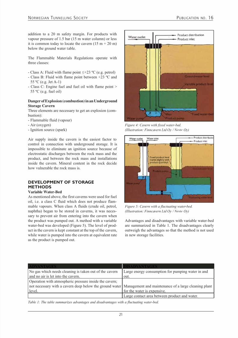
DEVELOPMENT OF STORAGEMETHODSVariable Water-BedAs mentioned above, the first caverns were used for fueloil, i.e. a class C fluid which does not produce flam-mable vapours. When class A fluids (crude oil, petrol,naphtha) began to be stored in caverns, it was neces-sary to prevent air from entering into the cavern whenthe product was pumped out. A method with a variablewater-bed was developed (Figure 5). The level of prod-uct in the cavern is kept constant at the top of the cavern,
while water is pumped into the cavern at equivalent rateas the product is pumped out.
Advantages and disadvantages with variable water-bedare summarized in Table 1. The disadvantages clearlyoutweigh the advantages so that the method is not used
in new storage facilities.
Figure 4: Cavern with fixed water-bed.
(Illustration: Finncavern Ltd Oy / Neste Oy)
ADVANTAGES DISADVANTAGES No gas which needs cleaning is taken out of the cavernand no air is let into the cavern.
Large energy consumption for pumping water in andout.
Operation with atmospheric pressure inside the cavern;not necessary with a cavern deep below the ground waterlevel.
Management and maintenance of a large cleaning plantfor the water is expensive.
Large contact area between product and water.
Figure 5: Cavern with a fluctuating water-bed.
(Illustration: Finncavern Ltd Oy / Neste Oy)
Table 1: The table summarizes advantages and disadvantages with a fluctuating water-bed.

7/21/2019 Publication 16
http://slidepdf.com/reader/full/publication-16 24/181
NORWEGIAN T UNNELLING SOCIETY PUBLICATION NO . 16
22
STORAGE UNDER PRESSURETo avoid the disadvantages mentioned in Table 1 andto avoid leaky storages, it became necessary to storethe products under pressure. The cavern will then actlike a closed pressure tank which operates with variable
pressure. It is therefore necessary with a deep locationso that the ground water pressure balance the pres-sure inside the cavern. Today the caverns are normallydesigned for operation between +1.5 bars and -0.5 bar,a level that has been optimum in most cases. With amaximum operation pressure at +1.5 bars, the top of thecavern needs to be located at least 35 m (15 + 20) belowthe ground water table (Figure 6).
With a closed cavern and a maximum operating pressureit becomes necessary to have a gas cushion which canexpand and compress with a varying level of product
in the cavern. The law of ideal gases with constanttemperature says pressure * volume = constant. Withvariations in pressure between +1.5 bar and -0.5 bar,there is a need for 25 % extra gas volume in the cavern(i.e. if the storage volume needed is 100 000 m3, it isnecessary to make a cavern of 125 000 m3). This is anextra cost, but compensates for the disadvantages withvariable water-bed.
Vapours from oil products are not ideal gases.Evaporation and condensation will influence the pres-sure inside the cavern. This will stabilise the pressurearound the vapour pressure of the product over a period
and make the calculations conservative. Vapours from products with low vapour pressure will follow the ideal
gas law most closely. Products with a high vapour pres-sure, like propane doesn’t follow the ideal gas law at all.When there are small changes in pressure or tempera-ture, evaporation and condensation will occur almostinstantaneously. Storage for propane under pressure
does therefore not need 25% extra gas volume, but can be filled up to the ceiling.
Vapour pressure for propane is at about 6 barg at 10 ºC.The top of a propane cavern must therefore be locatedat least 80 m below the ground water table. In a warmerclimate, the vapour pressure is higher (about 8 bargat 20 ºC gives a location of at least 100 m below theground water table).
UNDERGROUND PUMP ROOMOnly submersible pumps are used in modern under-ground storage facilities. These pumps are submergedin the product and are directly connected to the end ofthe discharge pipe. The discharge pipe is hanging freelyinside a pipe sleeve, and is suspended from the groundsurface. (Figure 7).These pumps are usually electricallydriven with the motor directly connected to the pump,and the motor must be pressure sealed to avoid contactwith the product. Hydraulically driven pumps have also been used in some special cases.
During the 1970’s many storage facilities with an under-ground pump room were constructed (Figure 8). Thecapacity of submerged pumps was too low at that time,only about 1000 m3/hour. For an oil terminal a tanker
loading capacity of about 18 000 m3/hour would berequired, which made it impractical and too expensive
Figure 6: Storage under pressure. Principles with storage
under pressure together with the margin of safety.
(Illustration: Norconsult)
Figure 7: Submersible pumps in a LPG storage.
(Illustration: Neste Oy)

7/21/2019 Publication 16
http://slidepdf.com/reader/full/publication-16 25/181
NORWEGIAN T UNNELLING SOCIETY PUBLICATION NO . 16
23
to use submerged pumps. Using 3 conventional cen-trifugal pumps with 6000 m3/hour capacity each the jobcould easily be accomplished.
Underground pump room is an expensive solution andhas a number of safety problems:
- Fire- and explosion danger in connection with mainte-nance (especially class A fluids).
- Need for extensive fire detection- and extinguishingsystems.
- Need for powerful ventilation.- Emergency exits from the pump room 80-100 m below
the surface are necessary.- Water curtains are necessary to avoid leakage from thecaverns into the pump room.
Due to the higher cost and the safety problems describedabove, the pump room solution is no longer used fornew facilities.
WATER CURTAINSFor a cavern located a few meters below the groundwater level and operating at atmospheric pressure, thewater above the cavern will normally drain into thecavern. When storage under pressure was planned, it
became important to maintain the ground water levelabove the cavern at a proper level to avoid gas blowouts.
Figure 8: Underground pump room. Dry pump rooms were
built in the 70’s when submerged pumps did not have enough
capacity. (Illustration: Neste Oy)
Figure 9: Overview of underground storage caverns and
pump room. Pump rooms marked yellow.(Illustration: Norconsult)
To solve this problem, horizontal water curtains wasdrilled from small tunnels above the caverns or from theground surface (Figure 10). The pressure in these watercurtains are maintained at a few metre above the groundwater level.
Water curtains between the caverns are also neces-sary to avoid product leakage to neighbouring caverns(Figure 10). Cross-leakage of product must be pre-vented between caverns with different products, whilecross-leakage between caverns with the same productwill usually be allowed. In the illustration below thereare three different products with two caverns for each product. The water curtains for cross-leakage preventionare drilled from the same small tunnels as mentionedabove or from the surface. The distance between thedrill holes is dependant on the permeability of the rock,and the experience of the designer.
Figure 10: Water curtains drilled from small tunnels above
the caverns. (Illustration: Norconsult)
Bacterial growth in water curtainsWater curtains to prevent leakage between caverns must
be established before the product is introduced to thecaverns. There are examples showing that water curtainsestablished later have been plugged by bacterial growth.Oil consuming bacteria living in the interface betweenoil and water make parts of the oil into an organic polymer. This is a reddish brown, slimy material which plugs the drill holes and destroys the efficiency of thewater curtain system. The material is observed in mostunderground oil storage plants, and commonly in thewater-bed (the interface between water and product atthe bottom of the cavern).
Analyses have shown that optimum conditions for theseoil consuming bacteria are when the water has a pH atabout 9. There is no bacterial growth when pH < 4 or pH> 11. Cleaning of the drill holes has been efficient whena 15 % hypochlorite solution is used (15 ml/m3 water).Chlorination must probably be repeated at regular inter-vals to avoid new bacterial growth. Anti-icing additivesalso restrain the bacterial growth, but the solubility inwater is 200 times better than in the product. The addi-tives will quickly disappear into the ground water and be a pollutant. The additives must therefore be addedafter the product is pumped out of the cavern.
“Dry” caverns to avoid microbiological growthMicrobiological growth inside the caverns has been
7/21/2019 Publication 16
http://slidepdf.com/reader/full/publication-16 26/181
NORWEGIAN T UNNELLING SOCIETY PUBLICATION NO . 16
24
observed in connection with most oil products. This isa problem for both underground storage and storage insteel tanks. Micro-organisms do not live only from oil products. Free water containing sulphates and oxygen,or total lack of oxygen is vital necessities for the differ-
ent oil reducing bacteria and fungi which may develop.The growth depends on the temperature; below 10 ºCthe growth is very low for most bacteria. Caverns ina cold climate therefore have favourable conditionsregarding microbiological growth.
Micro-organisms depend on water to be able to live andmultiply, and it is natural to look at methods which canreduce the interface area between product and water.Concrete floor with a slope towards narrow channelsalong the side walls will reduce the water contactextensively at the bottom of the cavern. The channelsslope in the longitudinal direction of the cavern anddrain to the pump sump where the water is pumped out.An “umbrella” below the ceiling in the cavern may beinstalled to collect drops of water and lead it throughgutters to the bottom channels.
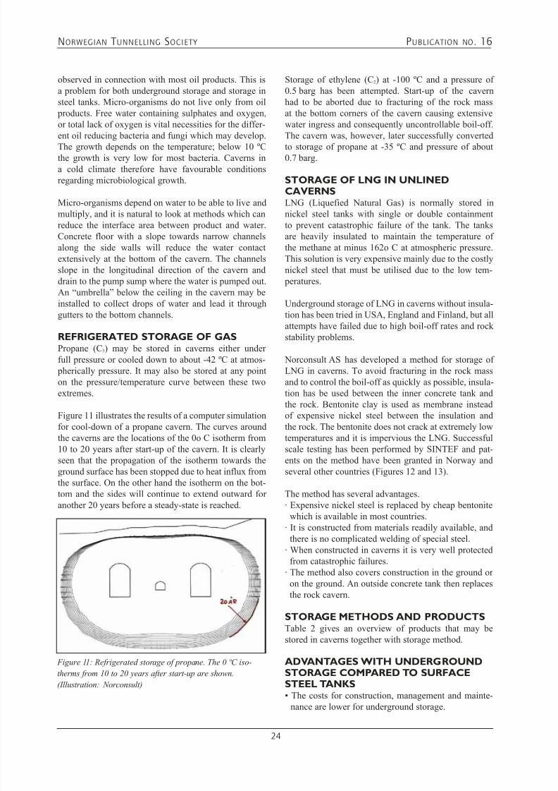
REFRIGERATED STORAGE OF GASPropane (C3) may be stored in caverns either underfull pressure or cooled down to about -42 ºC at atmos- pherically pressure. It may also be stored at any pointon the pressure/temperature curve between these twoextremes.
Figure 11 illustrates the results of a computer simulationfor cool-down of a propane cavern. The curves aroundthe caverns are the locations of the 0o C isotherm from10 to 20 years after start-up of the cavern. It is clearlyseen that the propagation of the isotherm towards theground surface has been stopped due to heat influx fromthe surface. On the other hand the isotherm on the bot-tom and the sides will continue to extend outward foranother 20 years before a steady-state is reached.
Storage of ethylene (C2) at -100 ºC and a pressure of0.5 barg has been attempted. Start-up of the cavernhad to be aborted due to fracturing of the rock massat the bottom corners of the cavern causing extensivewater ingress and consequently uncontrollable boil-off.
The cavern was, however, later successfully convertedto storage of propane at -35 ºC and pressure of about0.7 barg.
STORAGE OF LNG IN UNLINEDCAVERNSLNG (Liquefied Natural Gas) is normally stored innickel steel tanks with single or double containmentto prevent catastrophic failure of the tank. The tanksare heavily insulated to maintain the temperature ofthe methane at minus 162o C at atmospheric pressure.This solution is very expensive mainly due to the costlynickel steel that must be utilised due to the low tem- peratures.
Underground storage of LNG in caverns without insula-tion has been tried in USA, England and Finland, but allattempts have failed due to high boil-off rates and rockstability problems.
Norconsult AS has developed a method for storage ofLNG in caverns. To avoid fracturing in the rock massand to control the boil-off as quickly as possible, insula-tion has be used between the inner concrete tank andthe rock. Bentonite clay is used as membrane instead
of expensive nickel steel between the insulation andthe rock. The bentonite does not crack at extremely lowtemperatures and it is impervious the LNG. Successfulscale testing has been performed by SINTEF and pat-ents on the method have been granted in Norway andseveral other countries (Figures 12 and 13).
The method has several advantages.· Expensive nickel steel is replaced by cheap bentonite
which is available in most countries.· It is constructed from materials readily available, and
there is no complicated welding of special steel.
· When constructed in caverns it is very well protectedfrom catastrophic failures.· The method also covers construction in the ground or
on the ground. An outside concrete tank then replacesthe rock cavern.
STORAGE METHODS AND PRODUCTSTable 2 gives an overview of products that may bestored in caverns together with storage method.
ADVANTAGES WITH UNDERGROUNDSTORAGE COMPARED TO SURFACESTEEL TANKS
• The costs for construction, management and mainte-nance are lower for underground storage.
Figure 11: Refrigerated storage of propane. The 0 ºC iso-
therms from 10 to 20 years after start-up are shown.
(Illustration: Norconsult)

7/21/2019 Publication 16
http://slidepdf.com/reader/full/publication-16 27/181
NORWEGIAN T UNNELLING SOCIETY PUBLICATION NO . 16
25
Figure 12: Vertical cross-section of underground storage of
LNG developed by Norconsult AS.
(Illustration: Norconsult)
Figure 13: Underground storage of LNG developed by
Norconsult AS, horizontal section. (Illustration: Norconsult)
• It is possible to build below existing facilities, even process areas, and thereby getting double use of the property.
• An underground storage is better protected against oil
spills and fire disasters, and is environmentally better because of lower discharges to air and water.
Table 2: Overview of products that may be stored in unlined caverns
GASES REFRIGERATED OR UNDER PRESSURELNG ((C1) with insulation) -162 ºC, atmospheric pressureEthylene (C2) -100 ºC (may be possible even if unsuccessful the first time)Propane (C3) -42 ºC, atmospheric pressurePropane (C3) +10 ºC at about 6 barg
Butane (C4)+10 ºC at about 1,2 barg (refrigerated butane is not possible because storage temperature is too close to the freezing point for water)
FLUIDS (C5 - C8) UNDER PRESSURE (-0.5 TO +0.5 BARG) -Naphtha Dry concrete bottom
-Motor petrol Dry concrete bottom -Diesel oil Dry concrete bottom -Jet A-1 Dry concrete bottom, ”umbrella” -Heavy oil Water-bed / with heating -Crude oil Water-bed /with heating of heavy crudes
• The underground facilities are also much better pro-tected against sabotage.
• The product quality is better maintained for long timestorage because of stable temperatures inside the cav-
erns.
REFERENCES1. Neste Oy Brochure (December 1976): “Underground
Caverns - Safe, Economical, Non-Polluting”, 16 pages
2. Finncavern Ltd Oy Brochure (1980): “The Idea ofUnderground Oil Storing”, 16 pages
3. SENTAB / Skanska Cementgjuteriet Brochures onUnderground Cavern Storage

7/21/2019 Publication 16
http://slidepdf.com/reader/full/publication-16 28/181
NORWEGIAN T UNNELLING SOCIETY PUBLICATION NO . 16
26www.sweco.no
SWECO Grøner – Combined skills in
consulting engineering, environmental
management and architecture.
More than 80 years experience within:
• Energy
• Environment and Water Resources
• Industry/Structures• Transportation
• Underground Works and Engineering Geology
• Soil Mechanics and Foundation Engineering
For Rock Engineering and Underground Planning please contact:
SWECO Grøner P.O. Box 400, N-1327 Lysaker, Norway
Tel: +47 67 12 80 00, Fax: +47 67 12 58 40, E-mail: [email protected]

7/21/2019 Publication 16
http://slidepdf.com/reader/full/publication-16 29/181
NORWEGIAN T UNNELLING SOCIETY PUBLICATION NO . 16
27
4.2 GEOLOGICAL REQUIREMENTS AND CHALLENGES FOR
UNDERGROUND HYDROCARBON STORAGEEivind Grøv
INTRODUCTIONHydrocarbon storage may take place underground in anumber of different ways and the most typical might besuch as: aquifer storage, salt dome storage, abandonedmines storage, depleted oil and gas fields and finallyin mined rock caverns. This article is limited to dealwith the last storage concept, mined rock caverns beinggreatly the dominating method applied in Norway. Rockcaverns for hydrocarbon storage has been described inseveral articles and papers reporting that such storagehas taken place in a wide range of geological condi-tions.
A few basic principles apply for the suitability of theground conditions to host an underground, unlinedhydrocarbon storage, according to Ref. 1. These can
shortly be characterised as:• the rock types must not contain minerals which in
contact with oxygen or stored products can createaggressive or reactive chemical products,
• the rock mass must be of such quality that it enablesconventional tunnelling and excavation methods with-out requiring:
- comprehensive and extraordinary measures to sup- port the caverns or tunnels, and
- that ground water control can be done by rock massimpermeabilisation using pre-grouting.
These principles are of course based on the fact that thegreat majority of Norwegian hydrocarbon storage facili-ties are constructed according to an unlined concept,that is no steel lining or other types of lining of cast-in- place concrete or PVC or similar are required, neitherfor the containment nor for stability reasons. The rockmass is the main construction material both for a) host-ing the storage facility and b) keeping the stored productfrom evacuating.
Suitable ground conditions and rock mass for cavernconstruction exist throughout the world. A simplifiedoverview of suitable rock supplies for underground stor-
age is provided in a paper presented in 1987, Ref. 2.
Figure 1: Provinces with suitable rock for underground
hydrocarbon storage
A GENERALISED DESCRIPTION OF THEGEOLOGICAL BASIS IN NORWAY Norway forms part of a Precambrian shield. Two thirdsof the country is covered by Precambrian rocks (olderthan 600 million years), with different types of gneissdominating. Other rock types from this era are granites,gabbros and quartzite. Approximately one third of thecountry is covered by rocks of Cambrian - Silurian age.The greater part of these rocks are metamorphosed, but to a varying degree. Rocks such as gneisses, mica-schists and greenstones as well as sandstones, shales,
limestones and other un-metamorphosed rocks form amountain range, which runs through the central parts ofthe country. In the geologically unique Oslo region, therocks are partly made up of un-metamorphic Cambrian-Silurian shales and limestones and partly of Permianintrusive and extrusive rocks. These are the youngestrocks.
From an engineering geological point of view, Norwaymay be described as a typical hard rock province. Therocks have been subjected to folding and faulting, whichmay have a great influence on the stability in tunnelsand underground openings. Another complicating factor
is the irregular stresses in the rock masses, caused bytectonic events and further resulting from the steep and
7/21/2019 Publication 16
http://slidepdf.com/reader/full/publication-16 30/181
NORWEGIAN T UNNELLING SOCIETY PUBLICATION NO . 16
28
irregular topography. Also high tectonic and residualstresses are encountered.Due to the geological and tectonic events that haveformed the landscape, the rock mass is also severelycut by various types and generations of discontinuities,
from cracks and joints to zones containing totally disin-tegrated material. Tectonically, at present the provinceis tectonically stable for all practical aspects related totunnelling work.In Norway, the hydrogeological situation is dominated by a high, groundwater level, also in the rock massresulting from a generous amount of precipitation. Thissituation is both favourable and unfavourable for rocktunnelling. One advantage of a groundwater regimesurrounding an underground structure is that it providesa natural gradient acting towards the opening allowingthe utilisation of unlined storage facilities. On the otherhand, one disadvantage of such saturated conditionsis the risk that the tunnelling activity may disturb the
groundwater situation, thus imposing the potential ofadverse impact on surface structures and biotypes.
The rock itself is in practical terms impervious, and the porosity is negligible. This means that the permeability
(k) of a sound rock specimen is likely in the range of10-11 or 10-12 m/sec. Individual joints may have a permeability (k) in the range of 10-5 to 10-6 m/sec. Therock mass is consequently a very typical jointed aquiferwhere water occurs along the most permeable disconti-nuities. The permeability of the rock mass consisting ofcompetent rock and joints may typically be in the rangeof 10-7 to 10-9 m/sec.
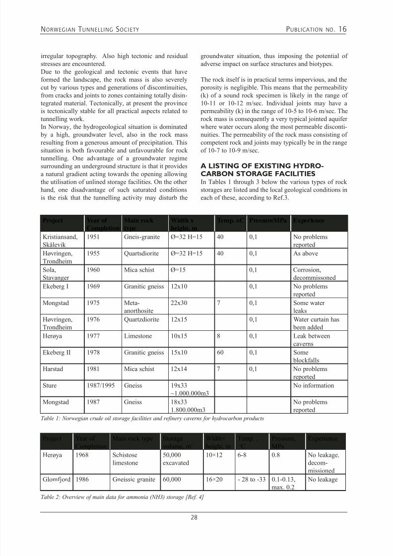
A LISTING OF EXISTING HYDRO-CARBON STORAGE FACILITIESIn Tables 1 through 3 below the various types of rockstorages are listed and the local geological conditions ineach of these, according to Ref.3.
Project Year ofCompletion
Main rocktype
Width xheight, m
Temp. oC PressureMPa Experience
Kristiansand,Skålevik
1951 Gneis-granite Ø=32 H=15 40 0,1 No problemsreported
Høvringen,Trondheim
1955 Quartsdiorite Ø=32 H=15 40 0,1 As above
Sola,Stavanger
1960 Mica schist Ø=15 0,1 Corrosion,decommissoned
Ekeberg I 1969 Granitic gneiss 12x10 0,1 No problems
reportedMongstad 1975 Meta-
anorthosite22x30 7 0,1 Some water
leaks
Høvringen,Trondheim
1976 Quartzdiorite 12x15 0,1 Water curtain has been added
Herøya 1977 Limestone 10x15 8 0,1 Leak betweencaverns
Ekeberg II 1978 Granitic gneiss 15x10 60 0,1 Some blockfalls
Harstad 1981 Mica schist 12x14 7 0,1 No problemsreported
Sture 1987/1995 Gneiss 19x33~1.000.000m3
No information
Mongstad 1987 Gneiss 18x331.800.000m3
No problemsreported
Table 1: Norwegian crude oil storage facilities and refinery caverns for hydrocarbon products
Project Year ofCompletion
Main rock type Storagevolume, m3
Width×height, m
Temp. , oC
Pressure,MPa
Experience
Herøya 1968 Schistoselimestone
50,000excavated
10×12 6-8 0.8 No leakage,decom-missioned
Glomfjord 1986 Gneissic granite 60,000 16×20 - 28 to -33 0.1-0.13,
max. 0.2
No leakage
Table 2: Overview of main data for ammonia (NH3) storage [Ref. 4]

7/21/2019 Publication 16
http://slidepdf.com/reader/full/publication-16 31/181
NORWEGIAN T UNNELLING SOCIETY PUBLICATION NO . 16
29
As has been shown in other articles in this publicationa number of compressed air storage facilities includingsuch as air cushion surge chambers have been con-
structed in Norway and these are listed below in table4 below.
Project Commis-sioned
Mainrock type
Storagevolume, m3
Width×height×length, m
Temp. ,oC Pressure,MPa
Experience
Rafnes 1977 Granite 100,000 19×22×256 ~ 9 0.65,tested at
0.79
No leakage
Mongstad 1989 Gneiss 3 caverns,total 30,000
13×16×64 6-7 Up to 0.6 No leakage
Mongstad 1999 Gneiss 60,000 21×33×134 - 42 0.15 Reduced capacity
Sture 1999 Gneiss 60,000 21×30×118 - 35 0.1 No informationavailable
Kårstø 2000 Phyllite 2 caverns,total 250,000
Approx.20×33×190
- 42 0.15 No leakage
Mongstad 2003 Gneiss 60,000 21×33×134 - 42 (propane)+8 (butane)
0.15 No information
Mongstad 2005 Gneiss 90.000 22x33x140 6-7 Recently put inoperation
Aukra 2007 Gneiss 63.000/180.000
21x33x9521x33x270
6-7 0,2 Not yetcommissioned
Table 3: Overview of main data for petroleum gas storage *) [Ref.4]
*) All with propane; Mongstad 1989 also stores butane and Sture 1999 stores a propane/butane mixture. Mongstad 2005 will be
naphthalene, Aukra 2007 will be condensate
The design of such compressed air storages rely verymuch on the same technical capacities of the rockmass as are relevant for the hydrocarbon storages listed
above.
Project Commis-sioned
Main rock type Excavatedvolume,m3
Crosssection,m2
Storagepressure,MPa
Head/ cover*)
Experience
Compressed air buffer reservoirsFosdalen 1939 Schistose greenstone 4,000 1.3 Minor leakage
Rausand 1948 Gabbro 2,500 0.8 No initial leakageAir cushion surge chambersDriva 1973 Banded gneiss 6,600 111 4.2 0.5 No leakage
Jukla 1974 Granitic gneiss 6,200 129 2.4 0.7 No leakage
Oksla 1980 Granitic gneiss 18,100 235 4.4 1.0 <5Nm3/h
Sima 1980 Granitic gneiss 10,500 173 4.8 1.1 <2Nm3/h
Osa 1981 Gneissic granite 12,000 176 1.9 1.3 Extensive groutingKvilldal 1981 Migmatitic gneiss 120,000 260-370 4.1 0.8 Water infiltr.
Necessary
Tafjord 1981 Banded gneiss 2,000 130 7.8 1.8 Water infiltr. Necessary
Brattset 1982 Phyllite 9,000 89 2.5 1.6 11Nm3/h
Ulset 1985 Mica gneiss 4,800 92 2.8 1.1 No leakage
Torpa 1989 Meta siltstone 14,000 95 4.4 2.0 Water infiltr. Necessary
Table 4: Overview of main data for compressed air storage, including air cushion surge chambers [Ref. 4]
*) Ratio between maximum air cushion pressure expressed as head of water and minimum rock cover
7/21/2019 Publication 16
http://slidepdf.com/reader/full/publication-16 32/181
NORWEGIAN T UNNELLING SOCIETY PUBLICATION NO . 16
30
As can be seen in tables 1 through 4 above the geologi-cal host rock in these various facilities vary a lot, thusindicating that a complex list of parameters and evalua-tions need to be taken into account prior to completingand deciding upon a final location and design/layout of
a project.
DEVELOPMENT OF UNDERGROUNDHYDROCARBON STORAGE FACILITIESIn Norway, the first underground hydrocarbon storageswere excavated during the Second World War, designedfor conventional, self-standing oil tanks. Later, beinglocated underground was basically for protective pur- poses during the cold war era. One project of such kindis located at Høvringen, near the city of Trondheimin central Norway, where ESSO is operating under-ground steel tanks, whilst one other storage is locatedat Skålevik, and is operated by BP. Following on fromthese first projects was underground hydrocarbon stor-age in steel lined rock caverns, designed and built inaccordance with for example Swedish fortificationstandards. This concept implies in brief a steel liningwith concrete backfill of the void space between thesteel lining and the rock contour. One such project islocated in Hommelvik outside Trondheim and is operat-ed by Fina. This project provides the supply of gasolineto the nearby airport. The above described projects werecommissioned almost a half a century ago, and are still being in operation. However, they represent an era anda concept which did not take into account the significant
capabilities of the rock mass.
The hydroelectric power development in the sixtiesrealised that the rock mass capabilities could be furtherutilised; large underground caverns, introduction ofwet-mix sprayed concrete, unlined head race tunnelsand air charge chambers were all contributions to anextended use of underground space. Thus the confi-dence in unlined tunnels and caverns grew, and thefirst unlined hydrocarbon storage project was initiated.Concept developments took place in other Scandinaviancountries at the same time, however, in Norway unlined
pressure shafts had been in use for some time in thehydroelectric power development, up to 1000m waterhead, and the importance of sufficient in-situ rock stressto prevent hydraulic splitting of the rock mass was rec-ognised as an important success criteria.
As mentioned above, in the Norwegian concept lining asa barrier had been abandoned due to the significant costsassociated with such solutions. Also the techniques of pre-grouting of the rock mass to stem or reduce waterleakage started to be developed during this period.Adding to this, caverns with large cross-sections andcomplicated lay-out geometry were already in use as
hydropower stations. Thus, the Norwegian tunnellingindustry was prepared and technically ready for the
new challenge of unlined hydrocarbon storage in rockcaverns.
In the 1970’s Norway grew to be a major oil and gas producing nation with the corresponding need for larger
storage facilities. It also became evident that the useof surface structures needed to be reconsidered. Thesolution in Norway was to excavate large rock caverns,utilising the availability of suitable rock mass condi-tions and the tunnelling experience obtained through thehydropower development.
Underground oil and gas storages mainly utilise the fol-lowing capabilities of the rock mass:
• Its impermeable nature, i.e. the actual permeability ofthe rock mass and associated discontinuities may varyfrom 10-5 m/sec to 10-11 m/sec.
• Its stress induced confinement, the in-situ stress situa-tion varying from stress released rock bodies through a pure gravitational stress situation to stresses originated by long tectonic history of the rock mass.
• Its thermal capacity, i.e. the capacity to store energyover significant amount of time.
• Its self-standing capacity, i.e. the ability of the rockmass to maintain stability even after being subject tocavities being made, man made or natural.
Taking into account that “mother nature” is not a per-fect material, and that the rock mass may have a set of
imperfections, it is most common that the construction process involves various techniques and methods toassist the design of a construction material that suits its purpose. In the following a short description of thesecapabilities will follow.
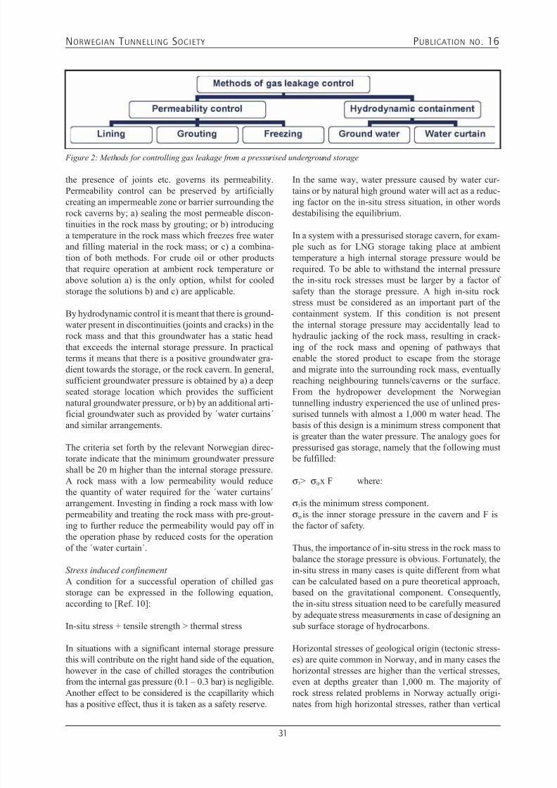
Permeability control and hydraulic containment
For permeability control and hydraulic containment theimpermeable nature of the rock mass is utilised withor without the assistance of construction techniques.The methods for controlling leakage from an unlinedunderground storage consist mainly of 1) permeability
control and 2) hydrodynamic control (or containment).In figure 6 it is schematically shown according toKjørholt [Ref.2].
By permeability control it is meant that leakage controlis achieved by maintaining a specified low permeabilityof the rock mass.
Permeability control may of course by obtained with-out any particular measure as listed above. This can beachieved by locating the rock caverns in a rock massthat has natural tightness sufficient to satisfy the speci-fied permeability.
However, the rock mass is a discontinuous media and
7/21/2019 Publication 16
http://slidepdf.com/reader/full/publication-16 33/181
NORWEGIAN T UNNELLING SOCIETY PUBLICATION NO . 16
31
Figure 2: Methods for controlling gas leakage from a pressurised underground storage
the presence of joints etc. governs its permeability.Permeability control can be preserved by artificiallycreating an impermeable zone or barrier surrounding therock caverns by; a) sealing the most permeable discon-tinuities in the rock mass by grouting; or b) introducinga temperature in the rock mass which freezes free waterand filling material in the rock mass; or c) a combina-tion of both methods. For crude oil or other productsthat require operation at ambient rock temperature orabove solution a) is the only option, whilst for cooledstorage the solutions b) and c) are applicable.
By hydrodynamic control it is meant that there is ground-water present in discontinuities (joints and cracks) in therock mass and that this groundwater has a static headthat exceeds the internal storage pressure. In practicalterms it means that there is a positive groundwater gra-dient towards the storage, or the rock cavern. In general,sufficient groundwater pressure is obtained by a) a deepseated storage location which provides the sufficientnatural groundwater pressure, or b) by an additional arti-
ficial groundwater such as provided by ´water curtains´and similar arrangements.
The criteria set forth by the relevant Norwegian direc-torate indicate that the minimum groundwater pressureshall be 20 m higher than the internal storage pressure.A rock mass with a low permeability would reducethe quantity of water required for the ´water curtains´arrangement. Investing in finding a rock mass with low permeability and treating the rock mass with pre-grout-ing to further reduce the permeability would pay off inthe operation phase by reduced costs for the operation
of the ´water curtain´.
Stress induced confinement
A condition for a successful operation of chilled gasstorage can be expressed in the following equation,according to [Ref. 10]:
In-situ stress + tensile strength > thermal stress
In situations with a significant internal storage pressurethis will contribute on the right hand side of the equation,however in the case of chilled storages the contributionfrom the internal gas pressure (0.1 – 0.3 bar) is negligible.
Another effect to be considered is the ccapillarity whichhas a positive effect, thus it is taken as a safety reserve.
In the same way, water pressure caused by water cur-tains or by natural high ground water will act as a reduc-ing factor on the in-situ stress situation, in other wordsdestabilising the equilibrium.
In a system with a pressurised storage cavern, for exam- ple such as for LNG storage taking place at ambienttemperature a high internal storage pressure would berequired. To be able to withstand the internal pressurethe in-situ rock stresses must be larger by a factor ofsafety than the storage pressure. A high in-situ rockstress must be considered as an important part of thecontainment system. If this condition is not presentthe internal storage pressure may accidentally lead tohydraulic jacking of the rock mass, resulting in crack-ing of the rock mass and opening of pathways thatenable the stored product to escape from the storageand migrate into the surrounding rock mass, eventuallyreaching neighbouring tunnels/caverns or the surface.From the hydropower development the Norwegiantunnelling industry experienced the use of unlined pres-
surised tunnels with almost a 1,000 m water head. The basis of this design is a minimum stress component thatis greater than the water pressure. The analogy goes for pressurised gas storage, namely that the following must be fulfilled:
σ3 > σip x F where:
σ3 is the minimum stress component.σip is the inner storage pressure in the cavern and F isthe factor of safety.
Thus, the importance of in-situ stress in the rock mass to balance the storage pressure is obvious. Fortunately, thein-situ stress in many cases is quite different from whatcan be calculated based on a pure theoretical approach, based on the gravitational component. Consequently,the in-situ stress situation need to be carefully measured by adequate stress measurements in case of designing ansub surface storage of hydrocarbons.
Horizontal stresses of geological origin (tectonic stress-es) are quite common in Norway, and in many cases thehorizontal stresses are higher than the vertical stresses,even at depths greater than 1,000 m. The majority of
rock stress related problems in Norway actually origi-nates from high horizontal stresses, rather than vertical

7/21/2019 Publication 16
http://slidepdf.com/reader/full/publication-16 34/181
NORWEGIAN T UNNELLING SOCIETY PUBLICATION NO . 16
32
stress due to the rock overburden. This has been the casein a number of road tunnels and tunnels connected tohydropower development, and high stresses have alsocaused considerable stability problems in power housecaverns. This has again called for rock stress and dis-
placement measurements.
However, the pure existence of high, or sufficient in-situ rock stresses, particularly horizontal stresses isan important condition that enable large undergroundcaverns to maintain stability, particularly when thewidth of the caverns exceed 12-15 m which is the sizeof an oversized road tunnel. The in-situ stresses are nor-mally exposing a nature which reflects the gravitationalcomponent in the vertical direction, whilst in the upper500 m typically the horizontal component is muchhigher than the could be derived at by a pure theoreticalapproach. Weaknesses occur as discontinuities in therock mass and they can exhibit rather varying charac-teristics and capabilities as far as being a constructionmaterial and may transfer stresses in different ways.
Thermal capacity of the rock mass
In Norway a number of cold storages were actuallyexcavated and in operation before the chilled gas con-cept was developed. The first of these underground coldstorages in unlined rock caverns was commissioned in1956, with an approximate number of 10 projects beingcurrently in operation. They were constructed with stor-age capacity in the range of 10-20,000 m3. Typically,
the temperature in these storages varies between –25 ºCto –30 ºC. These cold storages have mainly been builtfor the purpose of storage of food and consumer prod-ucts. Ice cream storage is one such utilisation.
From years of experience from the maintenance andrepair of these facilities the operators have gainedimportant experience regarding the behaviour of therock mass in frozen state as well as how the groundreacted upon changes in cooling capacity.
For example, on occasions the freezing element was
turned off and the temperature sensors in the rock masswere followed up to examine the temperature develop-ment in the storage caverns and the surrounding rockmass. A normal response to such changing circumstanc-es was a rather slowly increase of the temperature inthe rock mass. The 0-isotherme moved in a rather slowspeed towards the tunnel periphery, in the same way asit moves slowly outwards whilst freezing takes place.The thermal capacity of rock in general implies thatthe material has a significant capability of maintainingits frozen state, once it has been reached, a factor thatinfluences positively also to the cost aspects of thosehydrocarbon facilities.
Figure 3: Temperature gradient in rock around a cold
storage [Ref. 7]
Self-standing capacity
Most rock mass have a certain self-supporting capacity,although this capacity may vary within a wide range(Bienawski 1984). An appropriate engineering approachis to take this capacity into account when designing permanent support.
As for any type of underground structures the selectionof the site location, orientation and shape of the cavernsare important steps preceding the dimensioning and the
laying out of the underground site.
Rock strengthening may, however be needed to securecertain properties/specified capacities, the same way asis the case for any other construction material. The factthat, the rock mass is not a homogenous material shouldnot disqualify the utilization of its self-standing and load bearing capacity. Typically, rock support application in Norwegian oil and gas storage facilities consists mainlyof rock bolting and sprayed concrete. The application ofcast-in-place concrete lining in such facilities has beenlimited to concrete plugs and similar structures and is
normally not applied for rock support purpose. Therock support measures are typically not considered ascontributing to the containment, other than indirectly bysecuring the rock contour and thus preventing it fromloosening.
Furthermore, the Norwegian tunnelling concept applieswidely a drained concept, meaning that the rock supportstructure is drained and the water is collected and leadto the drainage system. Thus the rock support is notdesigned to withstand the full hydrostatic pressure in therock mass. The experience with large underground cav-erns was obtained in Norway during the development of
hydroelectric power schemes for which purpose a totalof 200 underground plants were constructed. Commonly
7/21/2019 Publication 16
http://slidepdf.com/reader/full/publication-16 35/181
NORWEGIAN T UNNELLING SOCIETY PUBLICATION NO . 16
33
the caverns for power-houses and hydrocarbon storagewere all typically seized to some 15-20 m width, 20-30 m high and tens-hundreds meter long.
Various types of monitoring to follow-up the behaviour
of the rock mass and the support structures are availableand used to document the stability and behaviour of therock mass.
Identification of design parameters
The location of the rock caverns are normally fixed inthe design concept and being based on information gath-ered during a comprehensive pre-investigation phase,however, pending on the actual rock mass conditionsas encountered during tunnelling in the approach tothe designed and planned location, relocation of theunderground structure may of course take place. Severalunderground projects in Norway have experiencedchanged locations and local optimisation to better adaptto the actual rock mass conditions. It is common to takeinto account such information as related to the follow-ing:
• Rock types and mechanical properties.• Characteristics and frequency, spacing of rock mass
discontinuities.• In-situ rock stresses.• Groundwater conditions.
During the approach to the planned location of thecavern(s) the rock mass is thoroughly mapped, jointsystems are observed and characterised, weaknesszones are interpreted, in-situ rock stresses are measured,ground water is monitored. If these conditions are not
in accordance with the expected and required quality ofthe rock mass, it may be conclusively decided to shiftthe location of the storage caverns, and other adjacentcaverns and tunnels, or make some layout adjustments.Typically, the final layout of the caverns, their location,geometry, alignment, lay-out of the tunnel system androck support design may not be finally decided uponuntil the above information is obtained from the exca-vation of the approaches of access tunnels. Numericalanalyses as well as analytical calculations are usefultools for the design and planning of the caverns. Thesemust of course be verified during the construction phase by adequate monitoring and follow-up of the stability ofthe under ground caverns.
REFERENCES1. Broch, Einar. Storage of oil and gas in rock caverns.
(In Norwegian) 19882. Frøise, Syver. Hydrocarbon storage in unlined rock
caverns: Norway’s use and experience. TUST. Vol.2, No.3 1987.
3. Grøv, Eivind. Storage of hydrocarbon products inunlined rock caverns. NFF Publication no. 15
THE OPTIMAL
SOLUTION FOR
ROCK BOLTING
The CT-Bolt is quickly
installed, easy grouted and
long lasting.
Visit us at www.ct-bolt.com

7/21/2019 Publication 16
http://slidepdf.com/reader/full/publication-16 36/181
NORWEGIAN T UNNELLING SOCIETY PUBLICATION NO . 16
34
Specialist waterproofing company
Ownership
Giertsen Tunnel AS is a privately owned,limited company based in Bergen, Norway.We offer our own patended waterproofingsolutions to tunnels and rock caverns worldwide. The company is a part of the GiertsenGroup, established in 1875.
Staff Giertsen Tunnel AS has a staff of profes-sional employies that have worked morethan 20 years in the field of waterproofing.
Main productsWG Tunnel Sealing System (WGTS) is apatended system, which in an effective andinexpensive way gives a permanent sealingof humid rock walls and ceilings.
The WGTS system is a complete package of humidity sealing of any rock surface in rockcaverns, shafts and adit tunnels. The systemsis offered complete installed or with use of local labour supervised by our specialists.
Combined with dehumidifiers, the systemprovides an ideal enviroment for corrosion-free storage of sensitive equipment etc. forboth civil and military purposes.
The WGTS will give you complete humiditycontrol year round and low energy cost outrange the alternative solutions.
The WGTS system can be used for- Hydro Electric Power Plants- Public Fresh Water Supply- Sports Centre- Military- Storage room- Civil Defence Shelter- Technical installations etc.
WG Tunnel Arch (WGTA) is a completesystem for water leakage, humidityprotection and frost insulation of roadtunnels. WGTA is designed for low traffictunnels, and is known as the most costefficient waterproofing system in roadtunnels
References
This systems have been used on projects in:Zimbabwe, Nepal, Pakistan, Sweden, Italy,South Korea, Switzerland, Singapore,Finland, Iceland and Norway.
Other products
WG Membranes used for waterproofing of tunnels. We have membranes in PVC,HDPE, LDPE, FPO and PP.
Installation of WG Tunnel Sealing System in rock cavern
used for storage.
Installation of WG Tunnel Arch in the Rotsethorntunnel,
Norway.
Giertsen Tunnel AS Tel: +47 55 94 30 30Nygaardsviken 1 Fax: +47 55 94 31 15P. O. Box 78 Laksevaag E-mail: [email protected] Bergen/Norway www.tunnelsealing.com

7/21/2019 Publication 16
http://slidepdf.com/reader/full/publication-16 37/181
NORWEGIAN T UNNELLING SOCIETY PUBLICATION NO . 16
35
4.3 THE WATER CURTAIN – A SUCCESSFUL MEANS OF
PREVENTING GAS LEAKAGE FROM HIGH-PRESSURE,UNLINED ROCK CAVERNS
Halvor Kjørholt
Einar Broch
ABSTRACT In Norway, high-pressure air is stored in ten unlined rock caverns, called air cushion surge chambers.These surge chambers are characterized by pressuresup to 7.7 MPa and volumes up to 110,000 m3. This
paper describes the successful use of water curtains to prevent air leakage from three such caverns, evenwhen the storage pressure is twice the thickness of the
overburden. INTRODUCTIONThus far, no hard rock storage has been developedspecifically for storage of natural gas or as a CAES(Compressed Air Energy Storage), although much workhas been carried out to establish the economic and tech-nical basis for such storage. The main concerns with
regard to the acceptance of the hard rock concept are prevention of gas leakage through the fractured rockmass and storage economy.
At present, hydrocarbon gases such as propane and butane are routinely stored in hard rock caverns, but ata much lower pressure than will be required for naturalgas storages and CAES. The only large-scale, high-pres-sure storage experience in hard rock caverns describedin the literature comes from ten Norwegian air cushionsurge chambers.
An air cushion surge chamber is a pressurized air-filledcavern, the function of which is to dampen transientsin the headrace tunnel of hydro power plants (Goodallet al. 1988). Figure 1 shows the design principle for ahydro power plant equipped with an air cushion surgechamber. The surge chambers are hydraulically con-nected to the headrace tunnel by a short(< 100-m-long) tunnel. The pressure in an air cushionis consequently dictated by the reservoir elevation. Thesurge chamber has a water bed below the air cushion.Compressors are used to fill and maintain the air cush-ion.
Figure 2 provides an overview of pressure and volumesfor the surge chambers in chronological order. The
first air cushion surge chamber was constructed at theDriva power plant, and commissioned in 1973 (Rathe1975); the last chamber began operating at Torpa power plant in 1989. Figure 2 also shows that as many as sixof the air cushions have pressures that exceed 4 MPa.The highest pressure is reached at Tafjord, where themaximum operating pressure is 7.7 MPa. The cavernvolumes are generally less than 20,000 m3; an excep-tion is the Kvilldal surge chamber, which has a volumeof 110,000 m3.
Three of the surge chambers (at Kvilldal, Tafjord andTorpa) are equipped with so-called water curtains torestrict the air leakage through the rock. These watercurtains are arrays of boreholes, with typical hole spac-ing of 5 to 20 m, drilled above the rock chamber. Water
at a pressure slightly higher than the air pressure in thecavern is fed into the holes. Thus, an artificially highgroundwater pressure is established around the cavern.This high pressure prevents air from leaking through thesurrounding rock mass.
This paper describes the design and construction of suchwater curtains, and also discusses experience from ordi-nary operation and special tests performed at the threesurge chamber sites.
Methods to Limit or Eliminate Gas Leakage from a Gas
Storage
Figure 3 suggests different methods for limiting oreliminating leakage from anunderground gas storage. These methods are based ontwo main principles, – permeability control and ground-water control.
Permeability control means that the leakage is eliminatedor kept at an acceptable level by ensuring that the rockmass around the storage has a sufficiently low perme-ability. No general permeability-controlling techniquefor non-leaking storages is currently available for full-
scale commercial use. The most developed alternativeis the steel-lined storage. The authors believe that the

7/21/2019 Publication 16
http://slidepdf.com/reader/full/publication-16 38/181
NORWEGIAN T UNNELLING SOCIETY PUBLICATION NO . 16
36
frozen storage concept will prove to be a realistic andfavourable alternative. However, so far this concept hassuffered from low research activity. It is further believedthat cold storages equipped with a water curtain outsidethe frozen zone could be considered, in order to provide
a double barrier against leakage. Permeability control is,however, beyond the scope of this paper.
The principle of groundwater control is based on thefact that the presence of groundwater reduces gas leak-age. The leakage reduction, or degree of groundwatercontrol, depends on the magnitude of the groundwater pressure as compared to the storage pressure. Leakage prevention by groundwater control offers two possibili-ties: control based on either (1) the natural groundwater pressure; or (2) groundwater pressure that is artificiallyenhanced by use of a water curtain. The sealing effectof the curtain is conditional, depending on a somewhathigher water pressure in the boreholes than in the stor-age. In this way, an inward hydraulic gradient, highenough to prevent outward gas migration is established.The water curtain should cover at least the crown of thestorage. Under extreme conditions, a water curtain thatcompletely surrounds the storage may be necessary.
To completely avoid leakage by groundwater control,the groundwater pressure in all potential leakage paths,directed upward from the storage, must exceed thestorage pressure over at least a small (infinitesimal)distance.
Complete gas tightness based on natural groundwateris, in general, not an economical alternative for high- pressure storages because of the requirement that theallowable storage pressure must be low in relation to thethickness of the overburden. Therefore, a water curtainshould be used to increase the groundwater pressureartificially. This type of arrangement will allow a higherratio between storage pressure and depth, and willincrease the operational flexibility. Experience showsthat water curtains have been used successfully to avoidgas leakage at storages with pressure up to twice the
hydrostatic groundwater head.
EXPERIENCE FROM THREE AIRCUSHION SURGE CHAMBERS WITH WATER CURTAINSWater curtains have been installed at three air cushionsurge chambers: Kvilldal, Torpa and Tafjord. Only atTorpa was the water curtain included in the originaldesign. The two other water curtains were constructedas a consequence of unacceptable air leakages. Thegeometry of the three caverns and water curtains is pro-vided in Figures 4, 7 and 10.
KvilldalThe Kvilldal air cushion operates at a pressure around4 MPa, with a minimum rock overburden of 520m in asteeply sloping terrain. The cavern was originally con-structed without a water curtain, but experienced an air
leakage of 240 Nm3/h after commissioning in 1981. Inan attempt to reduce (but not necessarily eliminate) thisleakage, an overlying water curtain, consisting of 47 percussion-drilled boreholes (diameter of 51 mm), wasinstalled in 1983. The geometry of the water curtain isshown in Figure 4. As can be seen, the water curtain isvery irregular, with borehole spacing of up to more than20 m in certain areas.
This water curtain has completely eliminated the airleakage through the rock. Tests have resulted in therelationship between water curtain over-pressure and airleakage shown in Figure 5. As indicated in the figure,any leakage through the rock is eliminated at Kvilldal ifthe potential in the water curtain exceeds the potentialin the air cushion (measured at cavern roof level) by 90m of water head.
In 1986, a water curtain supply pipe broke and put thewater curtain at Kvilldal out of commission. As can beseen in Figure 6, this action resulted in an increasing airleakage, approaching the level experienced before thewater curtain was installed (240 Nm3/h). However, theleakage developed quite slowly; in two months, only50% of this initial value had been reached. After the
water curtain was repaired in 1987, the leakage throughthe rock mass was eliminated again.
TafjordThe air cushion surge chamber at Tafjord (Figure 7) wasconstructed in 1982. The air cushion operates at a pres-sure between 6.5 and 7.7 MPa, while the minimum rockoverburden is only 440 m (steeply sloping terrain).
Like the Kvilldal facility, the Tafjord surge chamber wasoriginally constructed without a water curtain. Althoughthe leakage at this site was somewhat less than that at
Kvilldal, the compressors installed to maintain the aircushion did not have sufficient capacity. The surgechamber at Tafjord was therefore out of operation from1982 to 1990 (i.e., the cavern was completely filled withwater). Attempts to grout the surrounding rock did notimprove the leakage condition.
In 1990, a water curtain was installed at Tafjord, partlyas a research project. The curtain consists of 16 coredrilled holes (diameter of 56 mm), which cover both theroof of the cavern and the upper part of the cavern walls.Results from a water curtain test at the Tafjord air cush-ion are shown in Figure 8. The upper curve represents
the water curtain overpressure (difference between thewater curtain potential and the potential in the air cush-

7/21/2019 Publication 16
http://slidepdf.com/reader/full/publication-16 39/181

7/21/2019 Publication 16
http://slidepdf.com/reader/full/publication-16 40/181
NORWEGIAN T UNNELLING SOCIETY PUBLICATION NO . 16
38
More detailed guidelines for design and constructionof water curtains are presented in a doctoral thesis byKjørholt (1991), and are also presented in Kjørholt andBroch (1992).
SAFETY ASPECTSThe typical safety concern for a gas storage facility isrelated to leakages that can cause financial losses, fire,explosion; or which may be harmful to people and theenvironment in other ways.
The possible ways that leakage may occur at a gas stor-age facility isolated by a water curtain can be dividedinto three categories:1. Improper water curtain design or construction.2. Long-term effects.3. Operational problems.
Improper water curtain design or construction may causeminor leakages between water curtain holes, or outsidethe extension of the boreholes. Thorough hydraulic test-ing of the water curtain during construction, in additionto theoretical analyses, will minimize this risk. Still, if aleakage is experienced after commissioning, an increasein the water curtain pressure or a reduction in the stor-age pressure may be used to eliminate the leakage.
Long-term effects are related primarily to the possibil-ity that the boreholes may gradually become clogged.Clogging will result in an increased head loss near
the borehole walls and, thereby, reduced groundwater pressure between the boreholes. If this is the case, thegroundwater pressure will approach its critical valueover time, and eventually the storage will start to leak.A clogging phenomenon can be revealed by a reductionin water curtain consumption and reduced inflow to thestorage.
At least three effects may cause clogging:1. Particles in the water supply.2. Chemical precipitation.3. Bacterial growth.
By treating the water, it should be possible to reduce oreliminate these effects; Andersson et al. (1989) discuss-es possible actions that can be taken. If a critical reduc-tion in water curtain efficiency occurs, immediate actionshould be taken to increase the water curtain pressureor to restrict the maximum storage pressure. In the caseof bacterial clogging, it has been found possible to re-establish the water curtain by high-pressure flushing ofthe individual holes (Barbo and Danielsen 1980).
Operational problems, the third possibility for a watercurtain failure include all possible problems in keeping
the water curtain pressure at the desired level. Typical problems in this category are insufficient supply of
water or power, and failure in pumps, pipelines andmonitoring systems. It is believed that the desired levelof safety against this kind of failure can be obtainedthrough the use of black-up systems.
CONCLUSIONSExperience from the use of water curtains at the three Norwegian air storages discussed herein, at pressuresfrom 4 to 8 MPa, is encouraging. It has been found thata properly designed water curtain totally eliminates anygas leakage from the storage, even for a storage pres-sure head that is only twice the thickness of the rockoverburden.
A water curtain may provide not only a cost-effectivemethod to restrict gas leakage from unlined hard rockcaverns; currently it also appears to be the only practicalway of totally preventing gas leakage from a high-pres-sure storage.
REFERENCESAndersson, Ö.; Gustafson, G.; and Schreiber, I. 1989.Groundwater contained natural gas storage – waterchemistry and water treatment. Vattenfall, FUD Report No. U(G) 1989/13, Stockholm, Sweden. (In Swedish).
Barbo, T.F. and Danielsen, S.W. 1980. Bacterial impair-ment of water curtain between oil storage caverns inrock. Proc. Intl. Symp. Subsurface Space, Rockstore 80,Stockholm, Sweden, Vol. I, 245-250. Pergamon Press,
Oxford, UK.
Goodall, D.C.; Kjørholt, H.; Tekle, T.; and Broch, E.,1988. Air cushion surge chambers for underground power plants. Water Power and Dam Construction(November), 29-34.
Kjørholt, H. 1991. Gas tightness of unlined hard rockcaverns. Doctoral thesis, Norwegian Inst. of Technology,Trondheim, Norway.
Kjørholt, H. and Broch, E., 1992. Hard rock CAES
caverns – leakage prediction and prevention. Proc. 2ndIntl. Conf. Compressed and Air Energy Storage, SanFrancisco,USA, 20p.
Rathe, L. 1975. An innovation in surge-chamber design.Water Power and Dam Construction (June/July), 244-248.
-
This paper was originally published in the journalTunnelling and Underground Space Technology, Vol.7, No. 2, pp.127-132, 1992. It is reprinted with the
permission of the publisher ELSEVIER.

7/21/2019 Publication 16
http://slidepdf.com/reader/full/publication-16 41/181
NORWEGIAN T UNNELLING SOCIETY PUBLICATION NO . 16
39
Figure 1. Concept of a power plant with an air cushion surge
chamber.
Figure 2. Volume and pressure of the air cushion surge
chambers.
Figure 3. Methods to limit or eliminate gas leakage from a pressurized underground storage.
Figure 4. Plan of Kvilldal air cushion surge chamber with
water curtain.
Figure 5. Air leakage at Kvilldal air cushion surge chamber
as a function of the difference between the water curtain
potential and the potential at the cavern roof.
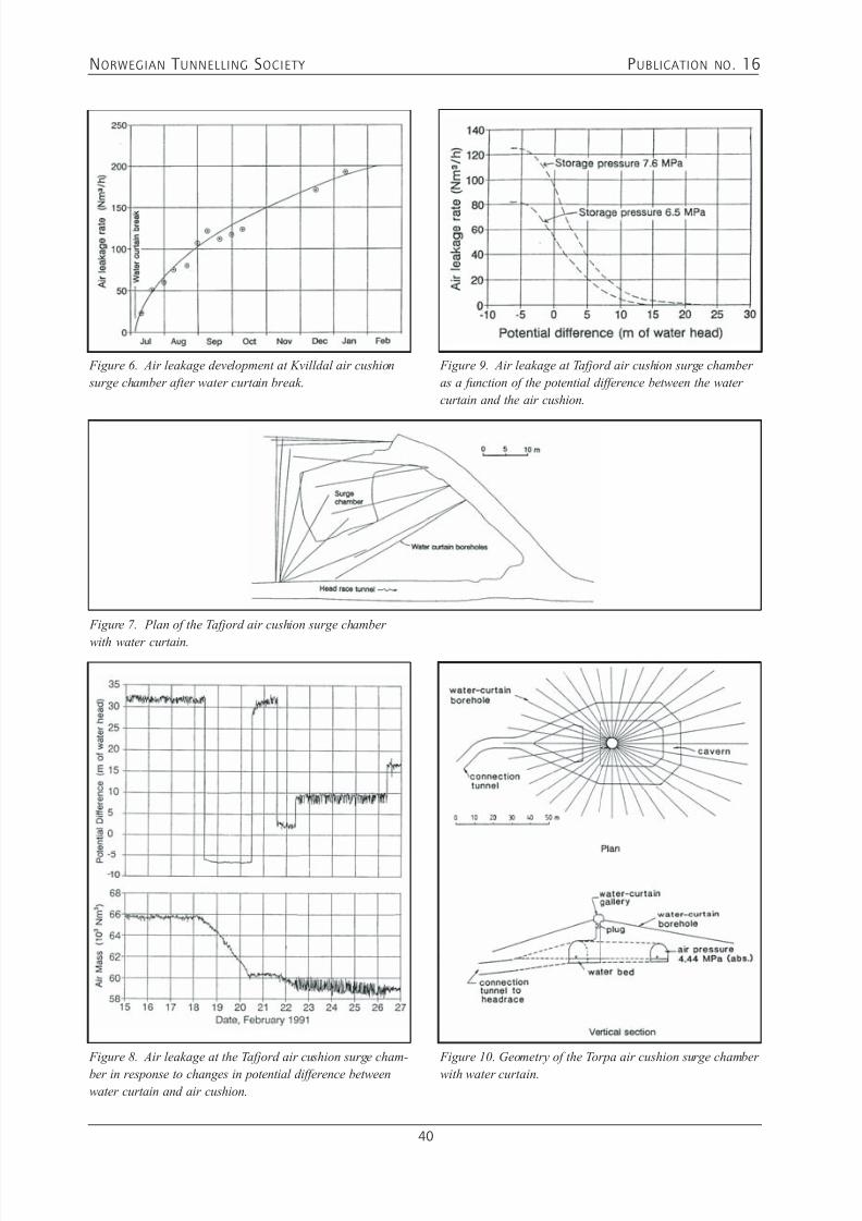
7/21/2019 Publication 16
http://slidepdf.com/reader/full/publication-16 42/181
NORWEGIAN T UNNELLING SOCIETY PUBLICATION NO . 16
40
Figure 6. Air leakage development at Kvilldal air cushion
surge chamber after water curtain break.
Figure 7. Plan of the Tafjord air cushion surge chamber
with water curtain.
Figure 8. Air leakage at the Tafjord air cushion surge cham-
ber in response to changes in potential difference between
water curtain and air cushion.
Figure 9. Air leakage at Tafjord air cushion surge chamber
as a function of the potential difference between the water
curtain and the air cushion.
Figure 10. Geometry of the Torpa air cushion surge chamber
with water curtain.
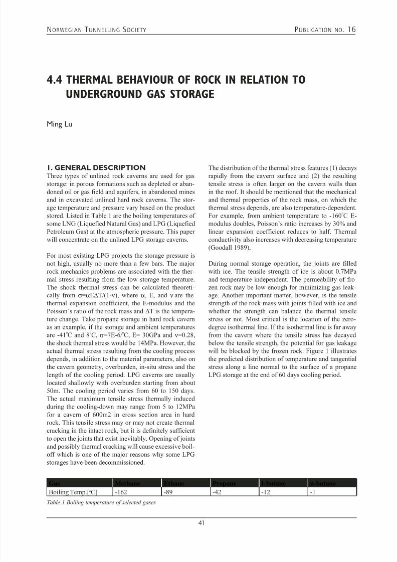
7/21/2019 Publication 16
http://slidepdf.com/reader/full/publication-16 43/181
NORWEGIAN T UNNELLING SOCIETY PUBLICATION NO . 16
41
4.4 THERMAL BEHAVIOUR OF ROCK IN RELATION TO
UNDERGROUND GAS STORAGEMing Lu
1. GENERAL DESCRIPTIONThree types of unlined rock caverns are used for gasstorage: in porous formations such as depleted or aban-doned oil or gas field and aquifers, in abandoned minesand in excavated unlined hard rock caverns. The stor-age temperature and pressure vary based on the productstored. Listed in Table 1 are the boiling temperatures ofsome LNG (Liquefied Natural Gas) and LPG (LiquefiedPetroleum Gas) at the atmospheric pressure. This paperwill concentrate on the unlined LPG storage caverns.
For most existing LPG projects the storage pressure isnot high, usually no more than a few bars. The majorrock mechanics problems are associated with the ther-mal stress resulting from the low storage temperature.The shock thermal stress can be calculated theoreti-
cally from σ=αE∆T/(1- ν), where α, E, and ν are thethermal expansion coefficient, the E-modulus and thePoisson’s ratio of the rock mass and ∆T is the tempera-ture change. Take propane storage in hard rock cavernas an example, if the storage and ambient temperaturesare -41
oC and 8
oC, σ=7E-6/
oC, E= 30GPa and ν=0.28,
the shock thermal stress would be 14MPa. However, theactual thermal stress resulting from the cooling processdepends, in addition to the material parameters, also onthe cavern geometry, overburden, in-situ stress and thelength of the cooling period. LPG caverns are usuallylocated shallowly with overburden starting from about
50m. The cooling period varies from 60 to 150 days.The actual maximum tensile stress thermally inducedduring the cooling-down may range from 5 to 12MPafor a cavern of 600m2 in cross section area in hardrock. This tensile stress may or may not create thermalcracking in the intact rock, but it is definitely sufficientto open the joints that exist inevitably. Opening of jointsand possibly thermal cracking will cause excessive boil-off which is one of the major reasons why some LPGstorages have been decommissioned.
The distribution of the thermal stress features (1) decaysrapidly from the cavern surface and (2) the resultingtensile stress is often larger on the cavern walls thanin the roof. It should be mentioned that the mechanicaland thermal properties of the rock mass, on which thethermal stress depends, are also temperature-dependent.For example, from ambient temperature to -160
oC E-
modulus doubles, Poisson’s ratio increases by 30% andlinear expansion coefficient reduces to half. Thermalconductivity also increases with decreasing temperature(Goodall 1989).
During normal storage operation, the joints are filledwith ice. The tensile strength of ice is about 0.7MPaand temperature-independent. The permeability of fro-zen rock may be low enough for minimizing gas leak-
age. Another important matter, however, is the tensilestrength of the rock mass with joints filled with ice andwhether the strength can balance the thermal tensilestress or not. Most critical is the location of the zero-degree isothermal line. If the isothermal line is far awayfrom the cavern where the tensile stress has decayed below the tensile strength, the potential for gas leakagewill be blocked by the frozen rock. Figure 1 illustratesthe predicted distribution of temperature and tangentialstress along a line normal to the surface of a propaneLPG storage at the end of 60 days cooling period.
Gas Methane Ethane Propane I-butane n-butane
Boiling Temp.[oC] -162 -89 -42 -12 -1Table 1 Boiling temperature of selected gases
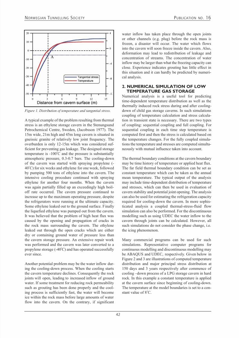
7/21/2019 Publication 16
http://slidepdf.com/reader/full/publication-16 44/181
NORWEGIAN T UNNELLING SOCIETY PUBLICATION NO . 16
42
A typical example of the problem resulting from thermalstress is an ethylene storage cavern in the StenungsundPetrochemical Centre, Sweden, (Jacobsson 1977). The15m wide, 21m high and 45m long cavern is situated ingneissic granite of relatively low joint frequency. Theoverburden is only 12-15m which was considered suf-ficient for preventing gas leakage. The designed storagetemperature is -100
oC and the pressure is substantially
atmospheric pressure, 0.3-0.7 bars. The cooling-downof the cavern was started with spraying propylene (-40
oC) for six weeks and ethylene for one week, followed
by pumping 500 tons of ethylene into the cavern. The
intensive cooling procedure continued with sprayingethylene for another four months. When the cavernwas again partially filled up an exceedingly high boil-off rate occurred. The cavern pressure continued toincrease up to the maximum operating pressure, despitethe refrigerators were running at the ultimate capacity.Some ethylene leaked out to the ground surface. Finallythe liquefied ethylene was pumped out from the cavern.It was believed that the problem of high heat flux wascaused by the opening and propagation of cracks inthe rock mass surrounding the cavern. The ethyleneleaked out through the open cracks which are either
dry or containing ground water of pressure less thanthe cavern storage pressure. An extensive repair workwas performed and the cavern was later converted to a propylene storage (-40
oC) and has operated successfully
ever since.
Another potential problem may be the water inflow dur-ing the cooling-down process. When the cooling startsthe cavern temperature declines. Consequently the rock joints will open, leading to increased inflow of groundwater. If some treatment for reducing rock permeabilitysuch as grouting has been done properly and the cool-ing process is sufficiently fast, the water will become
ice within the rock mass before large amounts of waterflow into the cavern. On the contrary, if significant
Figure 1. Distribution of temperature and tangential stress.
water inflow has taken place through the open jointsor other channels (e.g. plug) before the rock mass isfrozen, a disaster will occur. The water which flowsinto the cavern will soon freeze inside the cavern. Also,deformation may lead to redistribution of leakage and
concentration of streams. The concentration of waterinflow may be larger than what the freezing capacity canclose. Experience indicates grouting has little effect inthis situation and it can hardly be predicted by numeri-cal analysis.
2. NUMERICAL SIMULATION OF LOWTEMPERATURE GAS STORAGE
Numerical analysis is a useful tool for predictingtime-dependent temperature distribution as well as thethermally induced rock stress during and after cooling-down of child gas storage caverns. In such simulationscoupling of temperature calculation and stress calcula-tion in transient state is necessary. There are two typesof coupling: sequential coupling and full coupling. Forsequential coupling in each time step temperature iscomputed first and then the stress is calculated based onthe temperature changes. For the fully coupled simula-tions the temperature and stresses are computed simulta-neously with mutual influence taken into account.
The thermal boundary conditions at the cavern boundarymay be time history of temperature or applied heat flux.The far field thermal boundary condition can be set asconstant temperature which can be taken as the annual
mean temperature. The typical output of the analysismay include time-dependent distribution of temperatureand stresses, which can then be used in evaluation ofcavern stability and potential joint opening. The analysiscan also be used for estimating the refrigeration capacityrequired for cooling-down the cavern. In more sophis-ticated analysis a coupled thermal-stress-fluid flowsimulation can also be performed. For the discontinuousmodelling such as using UDEC the water inflow to thecavern through joints can be calculated. However, allsuch simulations do not consider the phase change, i.e.the icing phenomenon.
Many commercial programs can be used for suchsimulations. Representative computer programs forcontinuous modelling and discontinuous modelling may be ABAQUS and UDEC, respectively. Given below inFigure 2 and 3 are illustrations of computed temperaturedistribution and major principal stress distribution at150 days and 3 years respectively after commence ofcooling –down process of a LPG storage cavern in hardrock. In this example a constant temperature is appliedat the cavern surface since beginning of cooling-down.The temperature at the model boundaries is set to a con-stant value of 8
oC.

7/21/2019 Publication 16
http://slidepdf.com/reader/full/publication-16 45/181
NORWEGIAN T UNNELLING SOCIETY PUBLICATION NO . 16
43
3. CASE STUDY – COOLING-DOWNANALYSIS OF MONGSTAD LPGSTORAGE
The Mongstad gas storage facility is located in west Norway and consists of two caverns: One is for liquefied propane and the other is for butane. The storage temper-ature in the propane cavern is -40.5
oC. Two-dimensional
numerical simulations have been performed to evaluatethe thermally-induced stresses during cooling-down ofthe propane cavern. Three models are used in the analy-
sis, i.e. a continuous model, a double joint set model anda single joint model. Two cooling schemes, namely 60
Figure 2. Temperature distribution around a LPG cavern (a) 150 days and (b) 3 years after commence of cooling-down.
a(a) b(b)
a(a) b(b)
Figure 3. Distribution of major principal stress around a LPG cavern (a) 150 days and (b) 3 years after commence of cooling-down.
and 120 days, are analysed with the continuous model,in which both elastic and elasto-plastic material modelsare used in simulating the rock masses. The 126 m longcavern has varying cross sections of which the maxi-mum is 21 m wide and 33 m high at the cavern end. Thetwo dimensional numerical model is taken from here.This paper will focus on the continuous modelling.
The sequentially-coupled transient heat transfer andstress computation is performed by using the Distinct
Element code, UDEC. The temperature distribution iscomputed first based on given heat fluxes on the cavern

7/21/2019 Publication 16
http://slidepdf.com/reader/full/publication-16 46/181
NORWEGIAN T UNNELLING SOCIETY PUBLICATION NO . 16
44
boundaries, which is then followed by the stress compu-tation. Since this is a non-linear analysis, computationsare carried out in a step-wise manner with 10 day as thetime increment. In other words, the stress computationis performed following each heat transfer computation
for 10 days. The Mohr-Coulomb model is adopted as theyielding criterion for the elasto-plastic analysis. Rock bolts and shotcrete are also included in the model. The 4m long bolts are distributed along the cavern contour inspacing of 1.8 m. The shotcrete is 15 cm thick.
The material parameters used in the simulations arelisted below.
• E-modulus [GPa]: 30• Poisson’s ratio: 0.28• Friction angle [
o]: 38
• Dilation angle [o]: 6
• Cohesion [MPa]: 0.5• Tensile strength [MPa]: 0.7• Density [kg/m3]: 2764• Heat conductivity [W/mK]: 1.64• Specific heat [J/kgK]: 786• Thermal expansion coefficient [m/mK]: 6.99E-6
The heat flux applied on the cavern boundaries areestimated by SINTEF Energy and is listed below inTable 2.
Table 2 Applied heat flux
Cooling period
Heat flux [W/m2]walls roof floor
60 33.5 31.7 36.9
120 24.9 24.3 27.5
In-situ rock stress is estimated as
Figure 4 shows the UDEC model for the analysis.Figures 5 and 6 show the time-history of the tempera-ture during the cooling period. Figures 7, 8 and 9 showthe distribution of temperature and principal stress at theend of 60 day cooling-down period. Figures 10, 11 and12 show the distribution of temperature and principalstress at the end of 120 day cooling-down period. Figure13 gives the zero isothermal line after 60 and 120 daycooling period. A maximum tensile stress of about 10MPa and a 5-6 m distressed zone are predicted from theelastic and elasto-plastic computation, respectively.
Figure 4. UDEC model.
Figure 5. Time-history of temperature during the 60 daycooling period.
Figure 6. Time-history of temperature during the 120 day
cooling period.

7/21/2019 Publication 16
http://slidepdf.com/reader/full/publication-16 47/181
NORWEGIAN T UNNELLING SOCIETY PUBLICATION NO . 16
45
Figure 7. Temperature distribution around the propane
cavern at the end of 60 day cooling period.
Figure 8. Distribution of principal stress around the propane
cavern at the end of 60 day cooling from elastic computation.
Figure 9. Distribution of principal stress around the propane
cavern at the end of 60 day cooling from elasto-plastic
computation.
Figure 10. Temperature distribution around the propane
cavern at the end of 120 day cooling period.
Figure 11. Distribution of principal stress around the
propane cavern at the end of 120 day cooling from elastic
computation.
Figure 12. Distribution of principal stress around the
propane cavern at the end of 120 day cooling from elasto-
plastic computation.
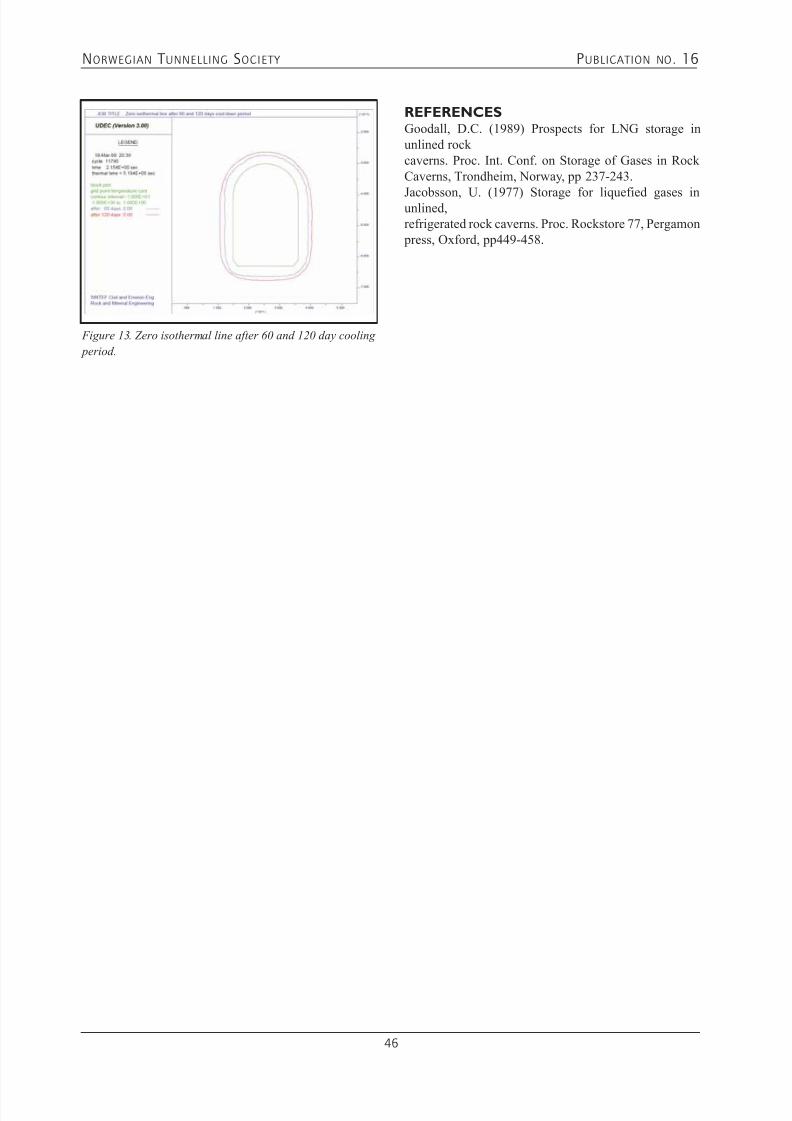
7/21/2019 Publication 16
http://slidepdf.com/reader/full/publication-16 48/181
NORWEGIAN T UNNELLING SOCIETY PUBLICATION NO . 16
46
REFERENCESGoodall, D.C. (1989) Prospects for LNG storage inunlined rockcaverns. Proc. Int. Conf. on Storage of Gases in RockCaverns, Trondheim, Norway, pp 237-243.
Jacobsson, U. (1977) Storage for liquefied gases inunlined,refrigerated rock caverns. Proc. Rockstore 77, Pergamon press, Oxford, pp449-458.
Figure 13. Zero isothermal line after 60 and 120 day cooling
period.

7/21/2019 Publication 16
http://slidepdf.com/reader/full/publication-16 49/181
NORWEGIAN T UNNELLING SOCIETY PUBLICATION NO . 16
47
5.1 CAVERN STORAGE EXCAVATION - STURE
Nils Olav Midtlien
THE STURE TERMINALThe Sture terminal in the municipality of Øygarden inCounty Hordaland in western Norway is an important port for shipping out crude oil. The terminal receivescrude oil and condensate from the offshore fields ofOseberg and Grane.
The oil is received via the Oseberg Transport System(OTS) through a 115-kilometer-long pipeline from theOseberg A platform and from the Grane field via theGrane Oil Pipeline (GOP) through a 212-kilometer-long pipeline.
The storage facilities at the Sture terminal comprise of anumber of unlined rock caverns. Five crude oil cavernsof 1 million cubic metres capacity in total, a LPG cavern
of 60,000 cubic metres and a ballast water cavern of200,000 cubic meters. The terminal also has a facil-ity for recovering VOC (volatile organic compounds),which is environmentally important during loading ofthe oil and gas vessels.
The processing facility at the terminal recycles thelightest components from crude oil, with these beingextracted as LPG mix (liquefied petroleum gases) andnaphtha. Refined crude oil and LPG mix are stored incaverns and then shipped out.
The terminal has two export jetties. Both of them canaccommodate oil tankers up to 300,000 dwt.
Photo: Norsk Hydro
The Sture terminal also exports LPG mix and naphtha by the Vestprosess pipeline to the Mongstad terminal.
AN IMPORTANT TERMINAL FOR THENORWEGIAN OIL AND GAS INDUSTRYThe terminal receives crude oil and condensate from anumber of offshore oil fields:Via the OTS pipeline crude oil and condensate areimported from:- Oseberg Field Center - Oseberg C- Oseberg East- Oseberg South- Tune- Brage
- Veslefrikk/Huldra
And via the GOP pipeline crude oil is coming from:- Grane
The following products are exported from the Stureterminal:- Oseberg Blend – crude oil and condensate from seven
platforms.- LPG mix – blend of propane and butane.- Naphtha – consists of pentanes and hexanes, used with
crude oil at refineries.
- Natural gas – methane and ethane, used for processheating at the terminal.- Grane Blend – crude oil from the Grane platform.
Approximately 250 oil tankers and LPG tankers arriveat the terminal per year.
THE REASONS FOR SELECTING STUREAS LOCATION OF THE TERMINALThe process for placing the terminal including the rockstorage caverns at Sture was based on a careful evalu-ation of several alternatives and by optimisation of anumber of factors like:
• Minimum of distance to the Oseberg oil field - to mini-mise import pipeline length. Photo: Norsk Hydro
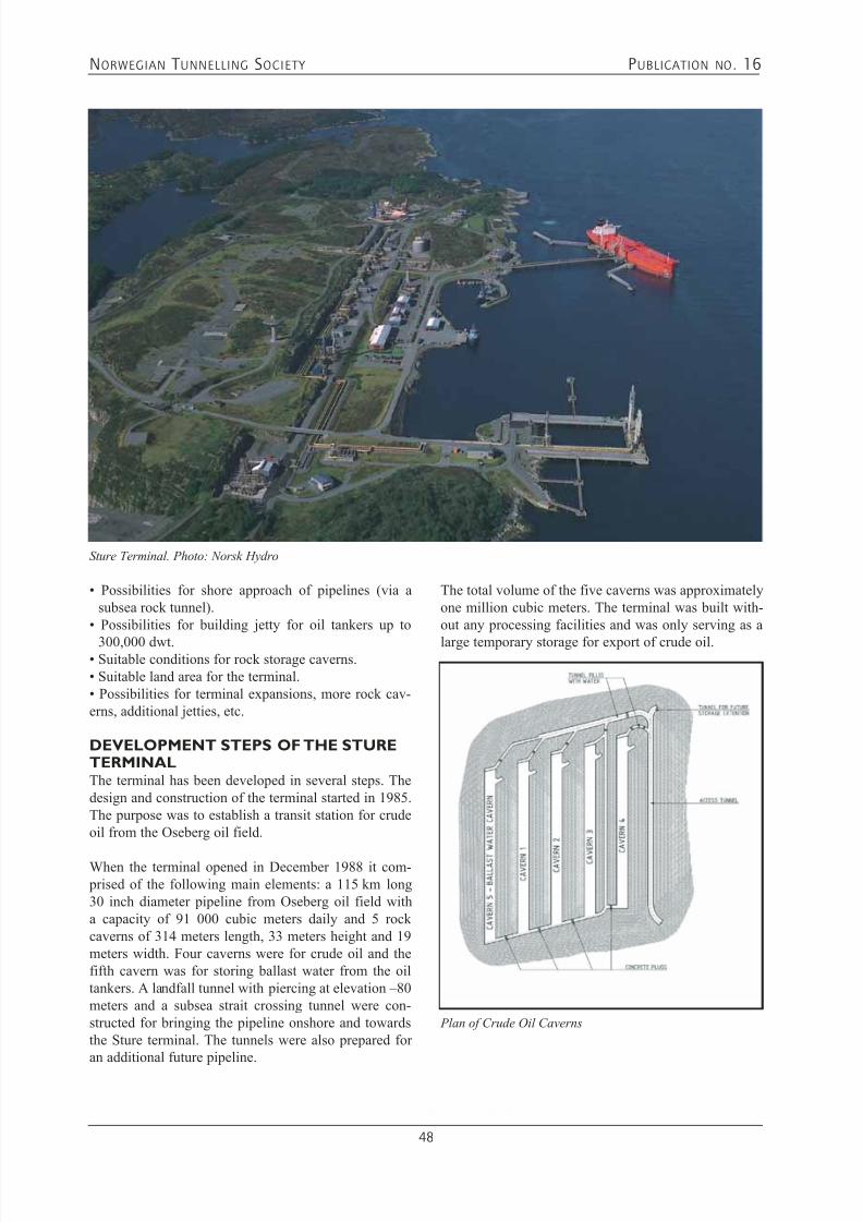
7/21/2019 Publication 16
http://slidepdf.com/reader/full/publication-16 50/181
NORWEGIAN T UNNELLING SOCIETY PUBLICATION NO . 16
48
• Possibilities for shore approach of pipelines (via asubsea rock tunnel).
• Possibilities for building jetty for oil tankers up to
300,000 dwt.• Suitable conditions for rock storage caverns.• Suitable land area for the terminal.• Possibilities for terminal expansions, more rock cav-erns, additional jetties, etc.
DEVELOPMENT STEPS OF THE STURETERMINALThe terminal has been developed in several steps. Thedesign and construction of the terminal started in 1985.The purpose was to establish a transit station for crudeoil from the Oseberg oil field.
When the terminal opened in December 1988 it com- prised of the following main elements: a 115 km long30 inch diameter pipeline from Oseberg oil field witha capacity of 91 000 cubic meters daily and 5 rockcaverns of 314 meters length, 33 meters height and 19meters width. Four caverns were for crude oil and thefifth cavern was for storing ballast water from the oiltankers. A landfall tunnel with piercing at elevation –80meters and a subsea strait crossing tunnel were con-structed for bringing the pipeline onshore and towardsthe Sture terminal. The tunnels were also prepared foran additional future pipeline.
The total volume of the five caverns was approximatelyone million cubic meters. The terminal was built with-out any processing facilities and was only serving as a
large temporary storage for export of crude oil.
Sture Terminal. Photo: Norsk Hydro
Plan of Crude Oil Caverns

7/21/2019 Publication 16
http://slidepdf.com/reader/full/publication-16 51/181
NORWEGIAN T UNNELLING SOCIETY PUBLICATION NO . 16
49
Cross Section of Crude Oil Caverns
Longitudinal Section of Crude Oil Cavern
In the year 1996 the storage facility was increased withone additional large rock cavern for condensate. Thevolume of the new U-shaped cavern was approximately300 000 cubic meters. The design principles for the new
cavern were similar to the existing storages.
In the year 2000 a process unit for stabilization of crudeoil / condensate to ensure correct quality of the OsebergBlend oil was finalized. The project named Sture CrudeUpgrade Project also included a LPG storage facility of60 000 cubic meters. One jetty was upgraded to handleexport of LPG.
The import pipeline from the Grane oil field was final-ized in year 2003. The spare capacity for an additional pipeline in the original shore approach tunnel systemwas utilized. At the terminal the large U-shaped cavern
was converted to a crude oil cavern.
STORAGE PRINCIPLES FOR ROCKCAVERNS FOR OILThe rock mass is not hundred percent watertight. For thisreason there will always exists a ground water level. The
principle for the oil storing in rock caverns is based onthe simple physical law that for oil products lighter thanwater surrounded by ground water with higher pressurethan the operating pressure inside the cavern, there willalways be water seeping into the rock cavern. The oilcannot leak out into to rock mass due to the higher exter-nal hydrostatic pressure of the ground water.
In Norway most rock cavern storages for petroleum products are based on a principle with fixed waterbed.The storages are also closed, which means that thegases above the oil have no direct communication to theatmosphere. The gas pressure inside the caverns varies
as a function of the oil level inside typically from 0.5 – 3 bara. Dependent on the type of crude oil, the pressure

7/21/2019 Publication 16
http://slidepdf.com/reader/full/publication-16 52/181
NORWEGIAN T UNNELLING SOCIETY PUBLICATION NO . 16
50
inside the cavern can in the long run gradually increase.If so, a portion of the gas has to be flared off.
At Sture three huge product pumps are installed in a pump pit in each cavern for ensuring a minimum of time
for filling up the crude oil vessels. In the lower sectionof the product pump pit it is installed water pumps for pumping out the polluted leakage water. The leakagewater has to be treated before it is discharged back intothe nature. To minimize the volume and then also thecost for handling leakage water it is important to sealoff leakages of water into the caverns during the exca-vation. The cost for handling of leakage water is relatedto the pumping cost and construction and operation ofa water treatment plant. At Sture it is also a limited vol-ume of fresh water available for artificially maintainingthe ground water table.
The ground water table serves as a natural seal.According to regulations in Norway the ground water pressure shall always as a minimum balance the maxi-mum operation pressure inside the rock cavern plus 20metres (2 bars) as a safety margin.To be able to ensure that the required elevation of theground water table is maintained, an artificial system forsupplying water is generally introduced. The artificialsystem can be made by injecting fresh water through 30 – 50 metres long holes drilled from the surface or froma tunnel system at a certain distance above the storage.The tunnel system can be combined with the access
tunnel and the complete system can then be filled withwater.
The elevation of the ground water table has to be checkedregularly. A simple way can be to drill a number of verti-cal observation holes above and surrounding the storagearea and manually measure the water level in each hole.By regular measurements the yearly variations and thelong-term trend can be found.
If the ground water level drops too low, there is risk forthe hydrocarbon filled atmosphere inside the cavern to
start blowing out. This would be a critical situation forthe storage and such a leakage can be very difficult torepair. In best case this will then give restrictions toactivities on the area above the storage.
By changing the pressure in the water supply lines it is possible to control the quantity of water injected intothe rock mass. This possibility can be important duringa long and dry season.
STORAGE PRINCIPLES OF ROCKCAVERNS FOR LPGTo reduce the volume of the LPG-storage, the gas has
to be stored as a liquid. There are two methods used themake the gas to a liquid, by reducing the temperature or
increasing the pressure. The most practical way for rockstorage is to reduce the temperature to approximately -30˚C at which point the LPG is liquid. The LPG storageneeds a special refrigeration unit for maintaining thetemperature.
The storage of LPG is basically made on the same main principles as for oil products. The ground water is usedas the seal for tightening the rock masses. The differ-ence will be that due to the cold temperatures the waterwill freeze to ice.
A special cool-down activity is also required for prepar-ing the storage for the first import of LPG. To seal off all
water leakages in LPG storages during the cool-down period is fundamental for operation and lifetime. Theleakages must be small as the heat energy in the waterin a big leakage might prevent it from freezing duringthe cool-down period. If the leakages are not sealed offduring the cool-down period, water continues to seepinto the cavern the water will freeze inside the cavernand cannot be pumped out. Due to this build up of icethe LPG pumps can be blocked off and the availablestorage volume reduced. After some time, the storagecan be considered as lost.
Typical temperature development in Rock Masses surround-
ing LPG caverns during cool-down of first Cavern. Figure:
Norconsult AS
Plan of LPG cavern

7/21/2019 Publication 16
http://slidepdf.com/reader/full/publication-16 53/181
NORWEGIAN T UNNELLING SOCIETY PUBLICATION NO . 16
51
Longitudinal Section of LPG cavern
GEOLOGICAL CONDITIONSThe rock mass at Sture consists of moderate to mediumfissured gneiss. The information about the rock massfor the first caverns was based on field mapping, coredrilling and special pump tests for defining the perme-ability.
The orientation of the caverns was decided based onfoliation, fissures etc. to give the most favourable sta- bility conditions and as a result a minimum of rocksupport.
The location of the first caverns was also selected takingany later extensions of the terminal and additional stor-age caverns into consideration.
OBSERVATION HOLES FOR GROUND WATER LEVELA system of vertical holes was drilled as soon as thelocation of the storage facilities was finally decided. The purpose was to collect detailed information about theground water level. The data is important for the designof the Ground Water Control System. The observationsshow also the magnitude of the variation of the groundwater level locally. ARTIFICIAL GROUND WATER
CONTROL SYSTEMAfter a detailed review of the geological information, asystem consisting of 54 mm diameter bore holes up tomore than 50 meters in length was designed to ensurethat the natural ground water level in the area could be maintained, despite the excavation of the caverns below, which could easily drain the area. The orientationof holes was selected with focus on crossing as manycracks and fissures in the rock mass as possible.
The ground water control system for the crude oilstorage caverns was established from the surface. Theadvantage was the unlimited number of possible access
points for drilling. A pipeline system between the holesand group of holes was located in trenches. The water
supply system had to be protected from frost. Groups ofholes were drilled almost horizontally above and verti-cally around the storage area. The storage caverns werelocated under the top of a hill and at the ends where theterrain dropped vertical holes were drilled to form a bar-
rier to avoid the ground water table to drop.
The pressure in the ground water supply system wasset to maintain a certain ground water table. The supplysystem was split into sections, which were controlled bya pressure reduction valve, manometer and a flow meter.To ensure the water supply and pressure a water towerof 1800 m3 was established.
There were two reasons for splitting up the water supplysystem into sections.Firstly, to allow for smaller sections to be sealed off dur-ing the following grout mass injection work in the cav-erns. This to avoid any grout masses to spread out intolarger parts of the system. As a precaution it was also seta limitation to the volume of grout masses to be injectedin each round of grout injection/injection hole.
Secondly, if a drop of ground water level should occurat a later stage, it was decided to include the flexibilityto be able to locally increase the water pressure in thesupply system to feed in more water to try to increasethe ground water level in that particular area.
To increase the possibilities to observe water leakages
the ground water control system was put into operationat least 50 metres ahead of the excavation of the topheading. Without the artificial water supply the areacould locally be drained before the geologists arrived atthe tunnel face for making their observations.
The long small diameter boreholes are a challenge forthe contractor due to deviation and must therefore becarefully drilled. A deviation of 18 meters in a less than50 meters long hole was documented.
In future projects with ground water control holes
established from a tunnel above the caverns the designcould be further improved by also filling the tunnel withwater, at least partly, prior to the cavern excavation. Dueto constraints in the construction schedule, the fillingof water might not be possible prior to the excavationof the top heading of the caverns but it should be filledwith water prior to start-up of excavating the upper bench.
REGISTRATION OF GROUND WATERLEVELThe registration of Ground Water Level should con-tinue during the lifetime of the storage facility. After the
construction period the information gained should beused as basis for how often the registrations should take

7/21/2019 Publication 16
http://slidepdf.com/reader/full/publication-16 54/181
NORWEGIAN T UNNELLING SOCIETY PUBLICATION NO . 16
52
place. Once per month could be a reasonable frequency.The requirement from the Authorities regarding theground water level should be documented.
The regulations for oil and gas terminals give clear
restrictions to the activities taking place within the area.This must be considered in the design of manholes forflow meters, manometers etc. to avoid that collectingthat data become a task involving many people andrequiring a lot of additional activities. An example isthat prior to entering a manhole, gas measurementsshould be performed by a person with documentedqualifications.
EXPLORATORY DRILLING DURINGEXCAVATIONIn the storage facility the rock masses 0 – 5 metersoutside the storage volume functions as a sealing mem- brane. The scope will then be to make the “membrane”as impermeable as possible. The purpose of the exten-sive exploratory drilling program was to detect as muchas possible of leakages and seal them off prior to exca-vation. The exploratory drilling was done systematically based on a pre-designed pattern and procedure.
The acceptance criterion for leakages is for oil and gas projects stricter than for most other type of projects. The petroleum products will pollute the water seeping intothe storage facility. The water has to be pumped out witha water head of typically 80 – 100 meters. A treatment
facility must also be available for cleaning the water.
CAVERN DIMENSIONSFor the crude oil caverns the dimensions were optimisedin the pre-design phase.Based on the expected quantities and cost for:• rock support.• rock mass sealing (grouting)• rock excavation• capitalized cost for pumping out the product
The lowest total cost for the storage facility was cal-
culated to be for a cavern width in the range of 18 to20 meters and a cavern height in the range of 32 to 34meters. The selected dimensions were 19 and 33 metersrespectively.
Each of the caverns was 314 meters long. At one end a15 meters deep pump pit was excavated. The pit in eachcavern was made as an extension downwards of an endwall, which gave a total height of up to 48 meters increating high tensions in the rock mass.
The pits should preferable have been moved at least 10
– 15 meters into the caverns to reduce the size of thehighest end walls. This would have reduced the com-
Typical Cavern Cross Section
Photo: Norsk Hydro

7/21/2019 Publication 16
http://slidepdf.com/reader/full/publication-16 55/181
NORWEGIAN T UNNELLING SOCIETY PUBLICATION NO . 16
53
Sleeves in Pump Pit, Weir in front of Pit
Photo: Norsk Hydro
plexity and extent of the rock support. When the sim- plification was realized it was too late for redesign dueto restrictions set by the installations above ground andthe ongoing drilling of shafts. Lack of rock cover was ahindrance for keeping the location of the pump pit andextending the cavern some 10 to 15 meters in length.
SHAFTSTo each of the 5 caverns it was drilled 9 shafts. Thetolerances for the shafts were strict. In shafts all equip-ment like pumps and instrumentation should be freehanging from the top flange just above terrain level. Thecontractor, Selmer (Skanska) and their sub-contractor
Entreprenørservice drilled all the 45 shafts in length of35 to 68 meters and the largest deviation was 300 milli-metres. Most shafts had a deviation less than 100 mm.
VERTICAL SHAFTS ABOVE THE PUMPPITInstrumentation: 1 pcs with diameter 2100 millimeters 1 pcs with diameter 600 millimetersCrude out: 4 pcs with diameter 2100 millimeters
(one spare)Water out: 1 pcs with diameter 2100 millimeters
In all shafts a steel sleeve was installed starting with aflange above ground level and down to the storage. Thesleeves stopped approximately where the shafts enteredinto the caverns.
The contractor planned very well the installation ofsteel sleeves in the vertical shafts. The largest sleeveswith a diameter of 1550 millimetres and length of 36meters arrived at the site in full lengths. The sleeveswere installed and ready for external concreting within3 days.
SHAFT FOR INFILL PIPELINE
Infill pipe: 1 pcs with diameter 1000 millimetresThe shafts for the infill pipelines were drilled down to a
niche at the bottom level of the caverns. From the nichethe pipelines were buried in a trench to the oppositeend of the caverns. The only exception was the cavern,which was combined with the transportation tunnel.Here the infill pipe ended up at the upper section of the
tunnel.
SHAFT FOR INSPECTIONInspection: 1 pcs with diameter 1000 millimetres
(located at centre of the caverns)
At the centre of each cavern a shaft was designed forinspection purposes. The inspections should take placeafter the concrete plugs were concreted, the manholesfinally closed and the external tunnel system filled withwater. The shafts were used for two different purposes:1. General inspection of the water tightness of concrete
plugs.2. For access to bring out a test plug from one cavern.
If a water leakage of unacceptable extent had beendetected, access via the inspection shaft is the onlyway to identify the type of leakage and point out exactlocation. This is of utmost importance for being able toknow how to plan and perform the improvement of thewater tightening of plug or rock masses.
At Sture a test plug was lost in one of the caverns dur-ing the commissioning phase. The cavern was alreadyfilled with 15 meters of water. Divers, equipment and an
inflatable rubber boat were lowered down the inspectionshaft. The divers used some extra time to find the blackcoloured test plug and bring it out.
DESIGN CRITERIA FOR STEEL SLEEVESA few meters at the upper end of all of the shafts thesteel sleeves were designed as pressure tanks. The lowerand main section of all shafts is considered as part ofthe cavern system. In the design it is considered that thesurrounding concrete and the rock mass directly supportthe steel sleeves. The external pressure during concret-ing was the design parameter for the lower section of
the sleeves.
ROCK EXCAVATIONThe entrance tunnel and the transport tunnel betweenthe caverns were both 10 meters wide to allow fortwo-way traffic. The entrance tunnel had also room for3 large diameter ventilation ducts. The branch tunnelswere designed for one-way traffic. See plan sketch ofthe 5 crude oil caverns.
The caverns were excavated with one top heading and3 benches. The two upper benches were drilled and blasted using ordinary tunnelling jumbos. The lowest
bench was drilled and blasted by means of vertical bor-ing jumbos.
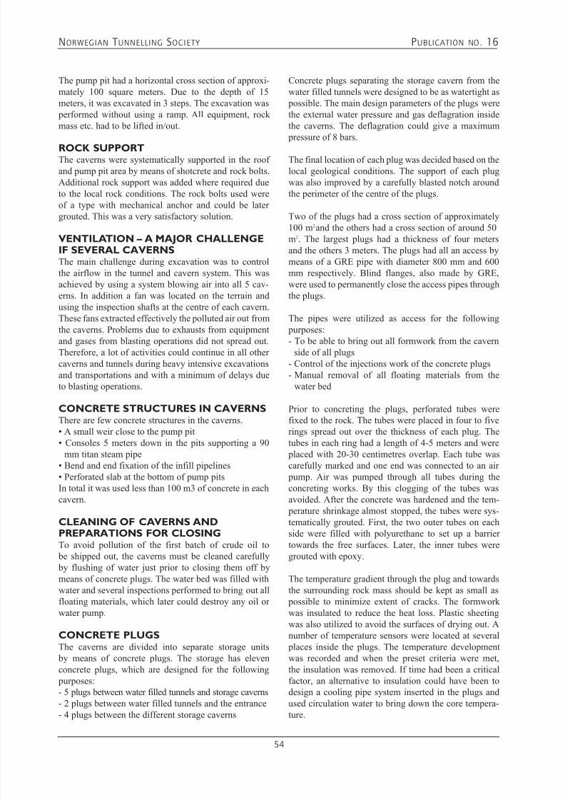
7/21/2019 Publication 16
http://slidepdf.com/reader/full/publication-16 56/181
NORWEGIAN T UNNELLING SOCIETY PUBLICATION NO . 16
54
The pump pit had a horizontal cross section of approxi-mately 100 square meters. Due to the depth of 15meters, it was excavated in 3 steps. The excavation was performed without using a ramp. All equipment, rockmass etc. had to be lifted in/out.
ROCK SUPPORTThe caverns were systematically supported in the roofand pump pit area by means of shotcrete and rock bolts.Additional rock support was added where required dueto the local rock conditions. The rock bolts used wereof a type with mechanical anchor and could be latergrouted. This was a very satisfactory solution.
VENTILATION – A MAJOR CHALLENGEIF SEVERAL CAVERNSThe main challenge during excavation was to controlthe airflow in the tunnel and cavern system. This wasachieved by using a system blowing air into all 5 cav-erns. In addition a fan was located on the terrain andusing the inspection shafts at the centre of each cavern.These fans extracted effectively the polluted air out fromthe caverns. Problems due to exhausts from equipmentand gases from blasting operations did not spread out.Therefore, a lot of activities could continue in all othercaverns and tunnels during heavy intensive excavationsand transportations and with a minimum of delays dueto blasting operations.
CONCRETE STRUCTURES IN CAVERNS
There are few concrete structures in the caverns.• A small weir close to the pump pit• Consoles 5 meters down in the pits supporting a 90
mm titan steam pipe• Bend and end fixation of the infill pipelines• Perforated slab at the bottom of pump pitsIn total it was used less than 100 m3 of concrete in eachcavern.
CLEANING OF CAVERNS ANDPREPARATIONS FOR CLOSINGTo avoid pollution of the first batch of crude oil to
be shipped out, the caverns must be cleaned carefully by flushing of water just prior to closing them off bymeans of concrete plugs. The water bed was filled withwater and several inspections performed to bring out allfloating materials, which later could destroy any oil orwater pump.
CONCRETE PLUGSThe caverns are divided into separate storage units by means of concrete plugs. The storage has elevenconcrete plugs, which are designed for the following purposes:- 5 plugs between water filled tunnels and storage caverns
- 2 plugs between water filled tunnels and the entrance- 4 plugs between the different storage caverns
Concrete plugs separating the storage cavern from thewater filled tunnels were designed to be as watertight as possible. The main design parameters of the plugs werethe external water pressure and gas deflagration insidethe caverns. The deflagration could give a maximum
pressure of 8 bars.
The final location of each plug was decided based on thelocal geological conditions. The support of each plugwas also improved by a carefully blasted notch aroundthe perimeter of the centre of the plugs.
Two of the plugs had a cross section of approximately100 m2 and the others had a cross section of around 50m2. The largest plugs had a thickness of four metersand the others 3 meters. The plugs had all an access bymeans of a GRE pipe with diameter 800 mm and 600mm respectively. Blind flanges, also made by GRE,were used to permanently close the access pipes throughthe plugs.
The pipes were utilized as access for the following purposes:- To be able to bring out all formwork from the cavern
side of all plugs- Control of the injections work of the concrete plugs- Manual removal of all floating materials from the
water bed
Prior to concreting the plugs, perforated tubes were
fixed to the rock. The tubes were placed in four to fiverings spread out over the thickness of each plug. Thetubes in each ring had a length of 4-5 meters and were placed with 20-30 centimetres overlap. Each tube wascarefully marked and one end was connected to an air pump. Air was pumped through all tubes during theconcreting works. By this clogging of the tubes wasavoided. After the concrete was hardened and the tem- perature shrinkage almost stopped, the tubes were sys-tematically grouted. First, the two outer tubes on eachside were filled with polyurethane to set up a barriertowards the free surfaces. Later, the inner tubes were
grouted with epoxy.
The temperature gradient through the plug and towardsthe surrounding rock mass should be kept as small as possible to minimize extent of cracks. The formworkwas insulated to reduce the heat loss. Plastic sheetingwas also utilized to avoid the surfaces of drying out. Anumber of temperature sensors were located at several places inside the plugs. The temperature developmentwas recorded and when the preset criteria were met,the insulation was removed. If time had been a criticalfactor, an alternative to insulation could have been todesign a cooling pipe system inserted in the plugs and
used circulation water to bring down the core tempera-ture.
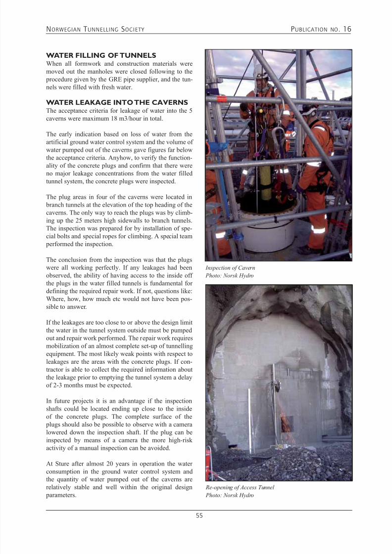
7/21/2019 Publication 16
http://slidepdf.com/reader/full/publication-16 57/181
NORWEGIAN T UNNELLING SOCIETY PUBLICATION NO . 16
55
WATER FILLING OF TUNNELSWhen all formwork and construction materials weremoved out the manholes were closed following to the procedure given by the GRE pipe supplier, and the tun-nels were filled with fresh water.
WATER LEAKAGE INTO THE CAVERNSThe acceptance criteria for leakage of water into the 5caverns were maximum 18 m3/hour in total.
The early indication based on loss of water from theartificial ground water control system and the volume ofwater pumped out of the caverns gave figures far belowthe acceptance criteria. Anyhow, to verify the function-ality of the concrete plugs and confirm that there wereno major leakage concentrations from the water filledtunnel system, the concrete plugs were inspected.
The plug areas in four of the caverns were located in branch tunnels at the elevation of the top heading of thecaverns. The only way to reach the plugs was by climb-ing up the 25 meters high sidewalls to branch tunnels.The inspection was prepared for by installation of spe-cial bolts and special ropes for climbing. A special team performed the inspection.
The conclusion from the inspection was that the plugswere all working perfectly. If any leakages had beenobserved, the ability of having access to the inside offthe plugs in the water filled tunnels is fundamental for
defining the required repair work. If not, questions like:Where, how, how much etc would not have been pos-sible to answer.
If the leakages are too close to or above the design limitthe water in the tunnel system outside must be pumpedout and repair work performed. The repair work requiresmobilization of an almost complete set-up of tunnellingequipment. The most likely weak points with respect toleakages are the areas with the concrete plugs. If con-tractor is able to collect the required information aboutthe leakage prior to emptying the tunnel system a delay
of 2-3 months must be expected.
In future projects it is an advantage if the inspectionshafts could be located ending up close to the insideof the concrete plugs. The complete surface of the plugs should also be possible to observe with a cameralowered down the inspection shaft. If the plug can beinspected by means of a camera the more high-riskactivity of a manual inspection can be avoided.
At Sture after almost 20 years in operation the waterconsumption in the ground water control system andthe quantity of water pumped out of the caverns are
relatively stable and well within the original design parameters.
Inspection of Cavern
Photo: Norsk Hydro
Re-opening of Access Tunnel
Photo: Norsk Hydro
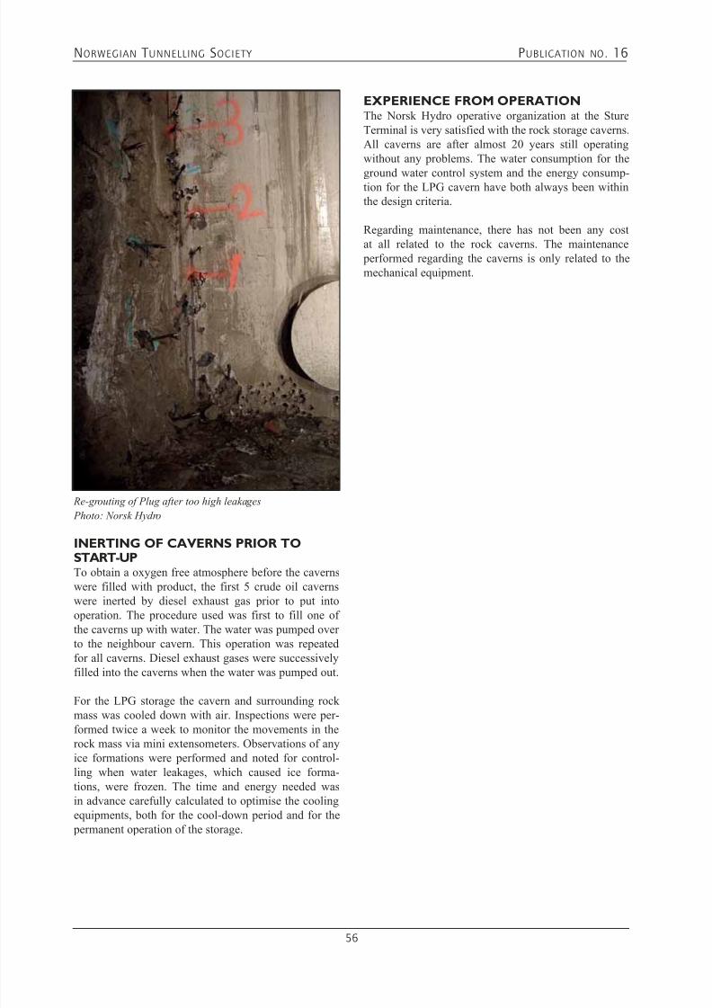
7/21/2019 Publication 16
http://slidepdf.com/reader/full/publication-16 58/181
NORWEGIAN T UNNELLING SOCIETY PUBLICATION NO . 16
56
Re-grouting of Plug after too high leakages
Photo: Norsk Hydro
INERTING OF CAVERNS PRIOR TOSTART-UPTo obtain a oxygen free atmosphere before the cavernswere filled with product, the first 5 crude oil cavernswere inerted by diesel exhaust gas prior to put intooperation. The procedure used was first to fill one ofthe caverns up with water. The water was pumped overto the neighbour cavern. This operation was repeatedfor all caverns. Diesel exhaust gases were successivelyfilled into the caverns when the water was pumped out.
For the LPG storage the cavern and surrounding rockmass was cooled down with air. Inspections were per-formed twice a week to monitor the movements in therock mass via mini extensometers. Observations of anyice formations were performed and noted for control-ling when water leakages, which caused ice forma-tions, were frozen. The time and energy needed wasin advance carefully calculated to optimise the coolingequipments, both for the cool-down period and for the permanent operation of the storage.
EXPERIENCE FROM OPERATIONThe Norsk Hydro operative organization at the StureTerminal is very satisfied with the rock storage caverns.All caverns are after almost 20 years still operatingwithout any problems. The water consumption for the
ground water control system and the energy consump-tion for the LPG cavern have both always been withinthe design criteria.
Regarding maintenance, there has not been any costat all related to the rock caverns. The maintenance performed regarding the caverns is only related to themechanical equipment.

7/21/2019 Publication 16
http://slidepdf.com/reader/full/publication-16 59/181
NORWEGIAN T UNNELLING SOCIETY PUBLICATION NO . 16
57
5.2 VPPC - VESTPROSESS PROPANE CAVERN PROJECT
Storage of liquid propane at atmospheric pressure in anunlined rock cavern
John Fjellanger Statoil Mongstad
John Jørgenvik Statoil/Vestprosess
Lars Murstam MIKA AS
Sven Oen MIKA AS
ABSTRACT: In the autumn of 2001 MIKA AS was contracted byStatoil, main operator of the Vestprosess project, to
construct a propane storage cavern. The cavern, locat-ed at Statoil’s Mongstad refinery, has a total volume
of 62,000 m3 and is intended to be a supplement to theexisting propane cavern at the plant. The new cavern
has been designed and constructed in much the sameway as the earlier one, although with the application
of different approaches for sealing off water inflows and for cooling the cavern. To minimise leakage ofwater into the cavern, stringent grouting standards
were imposed. As for the cooling process, instead ofusing direct propane cooling, the cavern was first cooled using air and then cooled further with propane.The cavern has the shape of a “lying bottle”, with theentrance to the cavern in the neck of the bottle. Access
to the cavern is through a 600-metre long access tun- nel at a grade of 1:7. The cavern is sealed with a con- crete plug in the neck of the bottle.
1. INTRODUCTIONThe Vestprosess project with its pipeline from Kollsnes
and Sture in Øygarden to the process plant at Mongstad,north of Bergen, presented Mongstad with new chal-lenges – the process plant became a major exporterof propane and butane. The “home market” (NorthernEurope) was not large enough, and there was thereforea need for storage capacity close to the process plant thatwas of sufficient volume to fill the largest freighters.In 1999, a cavern with 60,000 m3 of storage space for propane was constructed together with a similar cavernfor butane.
The propane storage cavern was fully cooled, that isto say that the propane was stored in liquid form at
atmospheric pressure and a temperature of -42 ˚C. Inthis propane cavern, the sealing and support work prior
to cooling was inadequate, resulting in a rock fall fromthe roof and an inleakage of about 20,000 m3 of waterwith subsequent ice formation after the cavern had beenfilled with propane. Through the experience gained dur-ing the first year of operation, the leakage was stoppedand the cavern was able to be kept in service – butwith an available storage volume of only 40,000 m3.However, the ice in the rock cavern caused substantialuncertainty as regards equipment and installations in the
cavern. Consequently, it was necessary to procure newstorage space by constructing another cavern.An investigation and review of the events in the first propane cavern resulted in there being every confidencein the concept, provided that the new cavern was con-structed to satisfactory standards.
From its opening in 1975, the Mongstad refinery hasconcentrated on the storage of oil in rock caverns.Today, 26 caverns containing crude oil and productsranging from heavy fuel oil to propane are in use atMongstad. The temperatures vary from 70 ˚C to -42 ˚C,and some storages caverns are constructed for pressures
of up to 6 bar.
Fig 1. Process plant at Mongstad

7/21/2019 Publication 16
http://slidepdf.com/reader/full/publication-16 60/181
NORWEGIAN T UNNELLING SOCIETY PUBLICATION NO . 16
58
For 28 years this storage method has proven to be asafe and reliable method. With high quality pumps andequipment in the caverns, the maintenance of a cavernsolution is much less costly than the maintenance ofa combination of tanks and pumps above ground. The
general level of safety is higher when the product is 25-100 metres below ground than when it is stored in hugetank farms above ground.
Good experience combined with low-cost constructionand operation and an excellent safety record are themain reasons why propane cavern CA-6106 has beenconstructed underground. It is the 27th rock cavern atMongstad, which highlights just how satisfied the useris with the rock cavern product.
2. DESCRIPTIONThe concept and project designAn impermeable zone of ice around the cavern sealsoff water inflows into a fully cooled propane cavern.The frozen zone is established by maintaining a water pressure in the rock around the zone, ie, a water curtainwith a supply of water from the surface. This networkof water supply over and around the cavern fills all newcracks and freezes to ice nearest the cavern surface.Regular checks are made to ensure that the water col-umn in the control wells around the cavern has a suf-ficient level to prevent gas leakage into the ground. In the case of the new propane cavern, it was decided
that the cooling should be done in two stages: first withair until the 0-isotherm in the rock had reached threemetres, and then further cooling with propane until thetemperature in the cavern had reached an operating tem- perature of -42 ˚C. With this solution, it was hoped thatany stability and inleakage problems would occur whilstthere was still an atmosphere made out of air in thecavern, and it was thus possible to implement measures before it was too late (ie, before a propane atmospherehad been established in the cavern).
Strategy to minimise water ingress
To make the cooling as efficient and simple as possible,it was decided that steps should be taken to minimisewater ingress into the cavern before the start of thecooling process. As a design criterion, inleakage wastherefore set to be < 15 l/min for the whole cavern.
Statoil and MIKA chose a solution involving systematic pregrouting as the most certain way of reducing theinflow of water into the cavern. A grouting programmewas drawn up on the basis of a philosophy of “thesimpler, the better”. The range of mixes was kept to aminimum, W/C=1 and W/C=0.8. All grout material wasmicro cement of the type Rheocem® 900 and the only
additive was the superplastisizer Rheobuild® 2000PF.Stop pressure for the grouting was set at 80 bar. The
decision to utilise this grouting material was made dueto its fast setting properties and good penetrating capa- bility.
The basic principle for the rock mass grouting works
was that the rock should be as watertight as possible 5metres outside the 0 isotherm, ie, 8 metres outside thecontour. Maximum distance between boreholes in agrout fan at maximum look-out was not to exceed 2.2metres. On the basis of these criteria, and highly varyingcavern geometry, each fan of grouting holes had its ownconfiguration. The cavern was blasted out at differentlevels (top heading and benches), and the pregroutingresulted in simultaneous pregrouting of the next level.See Figure 2.
Figure 2. Grout fans
All told, 30,000 metres were drilled for grouting. The
length of the fans varied slightly but in the main theywere 24 metres long.
Rock supportThe rock support application in caverns blasted out atdifferent levels can be a challenge as regards finding theappropriate amount of support to provide stability. Therock in the area consists of light and dark anorthosicgneiss, amphibolite and gabbro. It was important totake the freezing factor into account. How would, eg, bolts, behave at -42 ˚C? MIKA was asked to draw up a proposal for rock support classified in support classes.
In consultation with Geo Bergen, MIKA chose a clas-sification solution on the basis of sequential Q-valuecalculations – so that a given Q-value indicated a par-ticular support level. The solution involved four rocksupport classes:
A1 good quality rock • Q>10. Bolt pattern 2.5m x 2.5m and fibre-reinforced
shotcrete 8cm - 10cmA2 fair quality rock • 10>Q>4 Bolt pattern 2.0m x 2.5m and fibre-reinforced
shotcrete 10cm - 12cm.B1 Poor quality rock
• 4>Q>1 Bolt pattern 2.0m x 2.0m and fibre-reinforcedshotcrete 10cm - 15cm.

7/21/2019 Publication 16
http://slidepdf.com/reader/full/publication-16 61/181
NORWEGIAN T UNNELLING SOCIETY PUBLICATION NO . 16
59
B2 Very poor quality rock • 1>Q>0.1 Bolt pattern 2.0m x 1.5m and fibre-rein-
forced shotcrete 15cm - 20cm.
The bolt lengths varied between 4 and 5 metres. Five-
metre long bolts were used in the roof whilst 4-metre bolts were installed in the walls from the abutment anddownwards. All bolts were fully grouted 25 mm diam-eter re-bar bolts. In addition, CT bolts were used to pro-vide temporary support. In 85 % of the cavern, rock sup- port was provided according to support class B1. Localvariations were covered by the temporary support.
Creep and contraction of the steel bolts as a result ofthe cooling was not regarded as having any particularimpact on the stability of the rock cavern because of therelatively high safety factor. Birgisson (2002).
Groundwater controlTo maintain a groundwater pressure in the area aroundthe propane cavern, about 2000 metres of drilling wasdone using down-the-hole drilling equipment to estab-lish water curtains. Water-operated down-the-holedrilling equipment was described in the contract, butwas found not to work satisfactorily in the rock massat Mongstad. It was therefore decided to use pneumaticdown-the-hole drilling equipment with water flushingto ensure safe drilling in rock which might containgas pockets from existing adjacent caverns. The watercurtains consist of a horizontal water curtain drilled
from a side tunnel above or adjacent to the cavern anda vertical water curtain drilled from the surface. The boreholes have a diameter of 4”. It was intended thatthe water curtains should be established and put underslight pressure before cooling commenced. This was toensure that surrounding areas and solid rock would befilled with water, and become watertight when the waterfroze to ice.
3. EXECUTION OF THE PROJECT ANDEXPERIENCE GAINED
The final size of the cavern was a height of 34 metres, a
width of 21 metres and a total length of 134 metres. A pump pit is located immediately below shafts at the endof the cavern. The blasting was carried out by excavatingthe top heading first and then excavating the remainingvolume with two horizontally drilled benches. Access tothe cavern is through a 600-metre long tunnel excavatedat a grade of 1:7.
The cavern was sealed off in the neck of the bottle by aconcrete plug. The plug has to meet the same require-ments as regards water-tightness as the rest of the cav-ern, and was a challenge in itself.
Infill of propane into the cavern was enabled throughvertical pipes, fully grouted into raise bored shafts of
about 70 metres in length. A total of six shafts weredrilled to meet the need for infill and outpumping of product, instrumentation and the like. The infill proc-ess for cooling would take place via a spray systemmounted in the roof.
GroutingAs it had been decided to carry out systematic pregrout-ing, no probe drilling was done as it would only be ofacademic interest.
The actual grouting was basically done using two sepa-rate pump units. In addition, a reserve pump was avail-able at all times. The mixing process and registration ofthe grout takes was computer controlled. To withstand
the high grouting pressures, special disposable pack-ers were used that were reinforced with double back plates and extra locking rings. All valves and hoseswere approved for the high grouting pressures. Theexpansion of packers placed in holes were performedhydraulically.
After each completed grout fan, a round of control holeswas drilled. The number of control holes and their loca-tion was determined on the basis of the course of grout-ing of the main fan. In some instances where there werelarge grout takes in the round of control holes, a second
round of control holes was drilled
Special grouting measures were implemented aroundthe pump pit, end wall and shafts. The rock massaround the shafts was in addition pre-grouted from thesurface.Once blasting and grouting had been completed, waterleakage measurements were made. The result obtainedwas 2 l/min, well within the requirement of 15 l/min.
Rock supportThe poorest rock was encountered at the end of the cav-ern. The extent of CT bolt support was greatest here.
The permanent rock support remained as planned with-out taking into account to any appreciable degree the
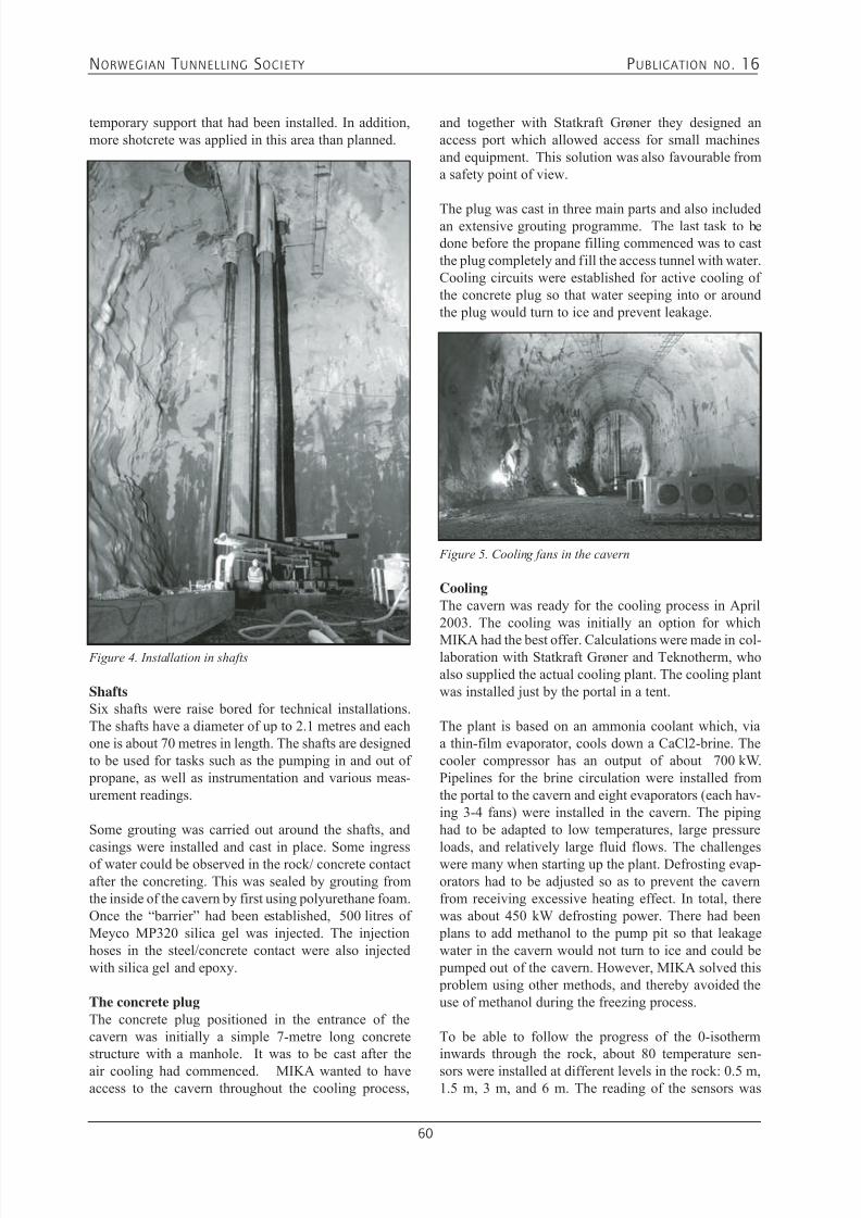
7/21/2019 Publication 16
http://slidepdf.com/reader/full/publication-16 62/181
NORWEGIAN T UNNELLING SOCIETY PUBLICATION NO . 16
60
temporary support that had been installed. In addition,more shotcrete was applied in this area than planned.
ShaftsSix shafts were raise bored for technical installations.The shafts have a diameter of up to 2.1 metres and eachone is about 70 metres in length. The shafts are designedto be used for tasks such as the pumping in and out of propane, as well as instrumentation and various meas-urement readings.
Some grouting was carried out around the shafts, and
casings were installed and cast in place. Some ingressof water could be observed in the rock/ concrete contactafter the concreting. This was sealed by grouting fromthe inside of the cavern by first using polyurethane foam.Once the “barrier” had been established, 500 litres ofMeyco MP320 silica gel was injected. The injectionhoses in the steel/concrete contact were also injectedwith silica gel and epoxy.
The concrete plugThe concrete plug positioned in the entrance of thecavern was initially a simple 7-metre long concretestructure with a manhole. It was to be cast after the
air cooling had commenced. MIKA wanted to haveaccess to the cavern throughout the cooling process,
Figure 4. Installation in shafts
and together with Statkraft Grøner they designed anaccess port which allowed access for small machinesand equipment. This solution was also favourable froma safety point of view.
The plug was cast in three main parts and also includedan extensive grouting programme. The last task to bedone before the propane filling commenced was to castthe plug completely and fill the access tunnel with water.Cooling circuits were established for active cooling ofthe concrete plug so that water seeping into or aroundthe plug would turn to ice and prevent leakage.
CoolingThe cavern was ready for the cooling process in April2003. The cooling was initially an option for which
MIKA had the best offer. Calculations were made in col-laboration with Statkraft Grøner and Teknotherm, whoalso supplied the actual cooling plant. The cooling plantwas installed just by the portal in a tent.
The plant is based on an ammonia coolant which, viaa thin-film evaporator, cools down a CaCl2-brine. Thecooler compressor has an output of about 700 kW.Pipelines for the brine circulation were installed fromthe portal to the cavern and eight evaporators (each hav-ing 3-4 fans) were installed in the cavern. The pipinghad to be adapted to low temperatures, large pressure
loads, and relatively large fluid flows. The challengeswere many when starting up the plant. Defrosting evap-orators had to be adjusted so as to prevent the cavernfrom receiving excessive heating effect. In total, therewas about 450 kW defrosting power. There had been plans to add methanol to the pump pit so that leakagewater in the cavern would not turn to ice and could be pumped out of the cavern. However, MIKA solved this problem using other methods, and thereby avoided theuse of methanol during the freezing process.
To be able to follow the progress of the 0-isotherminwards through the rock, about 80 temperature sen-
sors were installed at different levels in the rock: 0.5 m,1.5 m, 3 m, and 6 m. The reading of the sensors was
Figure 5. Cooling fans in the cavern
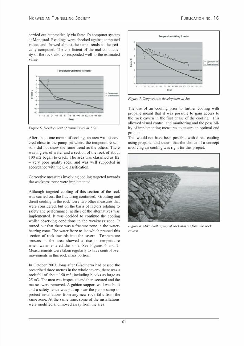
7/21/2019 Publication 16
http://slidepdf.com/reader/full/publication-16 63/181
NORWEGIAN T UNNELLING SOCIETY PUBLICATION NO . 16
61
carried out automatically via Statoil’s computer systemat Mongstad. Readings were checked against computedvalues and showed almost the same trends as theoreti-cally computed. The coefficient of thermal conductiv-ity of the rock also corresponded well to the estimated
value.
After about one month of cooling, an area was discov-ered close to the pump pit where the temperature sen-sors did not show the same trend as the others. Therewas ingress of water and a section of the rock of about100 m2 began to crack. The area was classified as B2 – very poor quality rock, and was well supported inaccordance with the Q-classification.
Corrective measures involving cooling targeted towards
the weakness zone were implemented.
Although targeted cooling of this section of the rockwas carried out, the fracturing continued. Grouting anddirect cooling in the rock were two other measures thatwere considered, but on the basis of factors relating tosafety and performance, neither of the alternatives wasimplemented. It was decided to continue the coolingwhilst observing conditions in the weakness zone. Itturned out that there was a fracture zone in the water- bearing zone. The water froze to ice which pressed thissection of rock inwards into the cavern. Temperature
sensors in the area showed a rise in temperaturewhen water entered the zone. See Figures 6 and 7.Measurements were taken regularly to have control overmovements in this rock mass portion.
In October 2003, long after 0-isotherm had passed the prescribed three metres in the whole cavern, there was arock fall of about 150 m3, including blocks as large as25 m3. The area was inspected and then secured and themasses were removed. A gabion support wall was builtand a safety fence was put up near the pump sump to protect installations from any new rock falls from thesame zone. At the same time, some of the installations
were modified and moved away from the area.
Figure 6. Development of temperature at 1.5m
The use of air cooling prior to further cooling with propane meant that it was possible to gain access tothe rock cavern in the first phase of the cooling. Thisallowed visual control and monitoring and the possibil-ity of implementing measures to ensure an optimal end product.This would not have been possible with direct coolingusing propane, and shows that the choice of a conceptinvolving air cooling was right for this project.
Figure 7. Temperature development at 3m
Figure 8. Mika built a jetty of rock masses from the rock
cavern.

7/21/2019 Publication 16
http://slidepdf.com/reader/full/publication-16 64/181
NORWEGIAN T UNNELLING SOCIETY PUBLICATION NO . 16
62
FACTS:• Volume blasted about 100,000m3, including access tunnel• Shotcrete about 2000m3• Drilling for grouting about 30,000 drilling metres• Grouting mass about 420 tonnes• Drilled shafts about 400 metres, diameter 2100mm.• Construction concrete 1600m3• Guided drilling/long-hole drilling for grouting and water curtains about 4000 metres• Number of working hours about 70,000 -1 injury resulting in
absence.
KEY PARTNERS: • MBT Degussa Grouting• Entreprenørservice Drilling of shafts• Nor Betong Concrete deliveries
• Vestnorsk Brønnboring Drilling of groundwater system• Norconsult Project design• Statkraft Grøner Project planning for concrete plug and cooling• Teknotherm Delivery of cooling plant• Rescon Mapei Various grouting jobs • Fjell Industrier Casings for shafts • Geo Bergen Geological surveys, assessment of rock support

7/21/2019 Publication 16
http://slidepdf.com/reader/full/publication-16 65/181
NORWEGIAN T UNNELLING SOCIETY PUBLICATION NO . 16
63
6. OWNERS CONTROL SYSTEMS FOR THE IMPLEMENTATION
Bjørn Helge Klûver
Ola Jegleim
Nils Borge Romslo
1. OWNERS CONTRACT PHILOSOPHYOwners Contract Philosophy will be decisively for thearrangement of the control system at site, and the waythe Site team is organized.A “Hands on philosophy” has been a normal way forexecution of large Norwegian underground civil worksfor the oil-and gas industry. Alternative organizing mod-els have been tried, without the same success.
The “Hands on philosophy” approach to the Site man-agement of a project will have as a prerequisite, a veryclose follow up from the Owner through all construction phases at site.Unexpected situations can be envisaged, interpreted anddecisions taken by a minimum loss of time. In the sameway necessary design changes of lay out etc,
can be handled with the best basis for a correctand favourable solution.The philosophy is based on the fact that theactual building material, rock, with its fre-quently change in quality, makes it difficultto foresee the real situation in forehand, andthereby describe the correct reinforcement androck support, at the Design office.Due to this fact the Site construction team,holding the sufficient geological competence, may takedecisions in matters of minor consequence, or, in mat-ters of great importance, can report back on deviations
to the Design office, often situated at a far distance froma remote underground project location.In some cases the Owner may prefer to move an engi-neering “Follow on team” direct on the site, to beenabled to minimize the distance and time for correctdecision taking. Other models for the Owner’s control system may also be preferred, like for example an EPCM-model (engi-neering, procurement, construction management) orsimilar arrangements.In this article the “Hands on Philosophy” will be the basis for the description.
2. THE ENGINEERING PHASEThe engineering will comprise several phases for largeunderground constructions, from the Feasibility studiesthrough the Concept phase up to the Basic engineering(Pre-engineering).When construction starts the Detail engineering phasewill cover the deliveries of drawings, specifications andnecessary procedures to the site.These phases are covered in other articles in this pub-lication.
A figure demonstrating the project phases from engi-neering through construction, commissioning and startof operation, is shown in figure 1.
3. SITE TEAM ORGANIZING /COMPE-
TENCE IN THE CONSTRUCTIONPHASEThe site team should be organized with managers hold-ing competence in underground civil works and engi-neering geology with at least 10-15 years of experience.Younger engineers with minor site experience shouldassist the managers with competence in engineeringgeology. The site managers should have had the oppor-tunity to participate in parts of the Basic engineering phase with Tender preparations and Award of contractsto the potential contractors. Normally the Norwegian underground excavation con-tracts include description of all possible construction
and support works to be executed at site with corre-sponding quantities expected.
Figure 1: Project phases

7/21/2019 Publication 16
http://slidepdf.com/reader/full/publication-16 66/181
NORWEGIAN T UNNELLING SOCIETY PUBLICATION NO . 16
64
This information will have to be based on map studies,site visits, seismic and probe drillings including groundwater tests etc.These investigations normally are of a high quality, butdo not give detailed data for the specific tunnels and
caverns location. The real updated information first becomes available for the Owner’s Site supervisionteam, when the rock is exposed after blasting at thetunnel face.
4. FOLLOW UP IN THE CONSTRUCTIONPHASE.
4.1 Ground water controlThe ground water level above the underground locatedconstruction is of crucial impact to maintain intact dur-ing the blasting period. Maintenance of this level may
perhaps be a greater challenge than the removal of rock.The natural hydrostatic characteristics of the groundwater should be disturbed as little as possible since it isextremely difficult to reinstate lost volume of pore pres-sure. Normally an intricate and finely balanced waterinjection system from the surface is established prior toany excavation. Consequently a programme for followup the piezometer locations must be worked out, andwill be one of the Site team’s main responsibilities tosupervise during the construction period.As a lowering of the ground water table may be diffi-cult to restore when first occurred, the establishment of
the wells for water supply into the ground water, mustcontinuously, during the blasting period, be broughtin operation at a correct distance ahead of the tunnelfront.The cavern depth is just determined by the fact thatground water level, shall, at all times be at least at a dis-tance equal to the maximum cavern overpressure, plus20m above the cavern ceiling.
4.2 Control at the tunnel frontOn the basis of earlier experience from rock conditionsat site, the Site team is able to take immediate actionsand give the contractor further instructions for the ongo-
ing work.This is particular valid for wall/ceiling and sole blast-
Fig.2: Modern underground storage under construction
ing, rock reinforcement work (bolting/shotcrete, castconcrete), for the adjusting of probe drillings ahead ofthe tunnel front and for the water sealing works.Through a close follow up the immediate support worksfor the construction workers in some cases may be com-
bined with the Owner’s permanent support work.It is of no doubt that operations like these mentionedabove, are best handled and accommodated by theOwner’s Site team, directly involved in the daily ongo-ing operations.
Fig.3: Impression of dimensions of underground
constructions
For these operations it is of great importance that thecontract includes descriptions of all actual work thatmay occur at site, and that adherent unit rates are
included.Anticipated quantities given in the contract, should onthe other hand not differ very much from the quantitiesrevealed during construction, still the tables for capacityfor different support works, are included in all modern Norwegian contracts for underground works (equivalenthours).Our experience from many years in Norwegian under-ground construction business, shows that an approachlike the above described, with a clear “hands on” organi-sation of the follow up work, should secure the Ownera sufficient high quality of work to a fair price, and
normally also within the milestones set in the ProgressSchedules for the work.There is a clear prerequisite for this, as mentioned ear-lier, no supervision team is able to handle such work ina satisfactory way without a proper knowledge and athorough practical experience from underground con-struction execution.Therefore the competence and composition of the Siteteam should be as we have pointed out in item 2 in thisarticle.
In figure 4 below the crucial site activities are listed:

7/21/2019 Publication 16
http://slidepdf.com/reader/full/publication-16 67/181
NORWEGIAN T UNNELLING SOCIETY PUBLICATION NO . 16
65
4.3 Concrete plugs-performance and tighteningAfter completion of the caverns the concrete plugs forshut off and tightening of each cavern are established.A proper filling up with concrete of the formwork forthe plugs requires correct concrete mix and applicationof suitable equipment.The injection hose installations and sequence of injec-tion of the plugs towards the rock surface, require agood planning and completion of the work.
4.4 Control towards 3.partyThe execution of the blasting with necessary warningand evacuation of other persons, stop in relevant neigh-
bouring work at site, use of sufficient alarm sirens, may be an important activity in certain periods for the Siteteam, to see to that this under proper control and wellaccommodated by the actual contractor.Further the observation of vibrations regarding impacton houses, constructions etc must be registered andevaluated. Blasting rounds should, if necessary, beadjusted to comply with acceptable vibration levels setin the contract.
The problem with drainage of ground water table fromsurrounding areas down into caverns or tunnels, may
impose settlements in foundation of nearby buildingsand constructions.The Site team will have the task to survey and observeinstalled instruments to decide if this may introduce a problem for the project or not.
5. HSE AND QA SYSTEMS ANDREQUIREMENTS DURINGCONSTRUCTION.
5.1 HSEAll owners of underground construction in Norwaytoday have a high profile on HSE. In additions tothe Owner’s internal requirements in this field, the
Norwegian Authorities will have a sharp observation onthe execution of work. Contractors with low score and
rating in the HSE field, will be out of question for theexecution of large underground works.The site team will, of course, be brought into the HSEwork with Qualitative risk analysis, Safe Job Analysis,Unplanned Incident Observations and Reporting, UnsafeAct Auditing, Safety Inspections Rounds at site etc.
5.2 Environmental controlThe environmental execution should comply with the NS-ISO 14001 requirements.The discharge permits from the Authorities must be fol-lowed up, and specially leakages and oil contaminatedtunnel water, pumped out from a temporary treatment
plant in the tunnels, and led to sedimentation basins inopen air, prior to the discharge water is let out in sea,river or water, must be in proper operation through theconstruction period.
5.3 Quality ControlThe Quality of the execution will be monitored through aQA system complying with NS-ISO 9001:2000 require-ments. A comprehensive detection and documentationwill be necessary for logging of the results and obser-vations at the tunnel fronts at any time, support work,injection work, piezometer logging etc.
6. PUMP SHAFTS /MECHANICALINSTALLATIONS
For crude oil and gas storage pump shafts must be estab-lished. Submerged pump installations are normal, butalso “dry-installed” solutions may be designed.The pump shafts normally are raise drilled, still shortershafts may be established through long-hole drilling and blasting.To maintain the ground water table around the shaftswill require a thorough plan for injection work prior tothe establishment of the shafts.
Several mechanical installations for warming up crudeduring unwaxing of the caverns in the Operation phase
N0. SITE ACTIVITIES FOLLOW UP1 Ground water level/pressure
controlExecuted by Owner. Contractor to perform the practical work(drilling of holes etc) according to Owner’s decision.
2 Blasting control Control executed by Owner. Blasting of contour holes shall notdamage tunnel contour, concrete structures etc.
3 Decision on rock support(reinforcement)
Contractor is responsible for his workers safety and decides temporaryrock support at the tunnel front. Owner to decide the permanentrock support and that all rock reinforcement has the project lifetimedurability.
4 Ground water sealing (grouting)in tunnel and at the tunnel faceduring excavation
Owner to decide number and length of holes, grouting pressure,composition and amount of quantities.
5 Other civil works actual forOwner’s control
Control as specified in the contract.
Fig.4: Important activities for the Site team

7/21/2019 Publication 16
http://slidepdf.com/reader/full/publication-16 68/181
NORWEGIAN T UNNELLING SOCIETY PUBLICATION NO . 16
66
may be established. Further instruments for level con-trol, ventilation to gas flare etc, may be brought in place.
Fig. 5: Pump shaft during construction
7. COMMISSIONING PHASE /PREPAREFOR INFILL OF PRODUCTS
A programme for commissioning and filling in of prod-ucts into the caverns, must be settled in due time priorto the execution.To avoid explosion in the gas zone above the crude, iffalling rock should create ignition, when hitting the rockwall, the caverns may partly be water filled with freshwater, if available (sea water should be avoided due tothe corrosion risk), before filling in crude, The rest ofthe cavern volume should be saturated by exhaust gas
or nitrogen (expensive). In this way a none explosiveatmosphere is achieved. The water should be pumpedfrom one cavern to the next one, as the caverns are filledwith crude during the commissioning.
During the filling up the site team should closely followup instruments, and detect if any leakage to the freeatmosphere of gas should occur.In such a case the filling must be stopped and supple-mentary injection must be supplied.
After completion of the underground civil works, the
Supervision team shall produce a report covering allcivil works that have been carried out. This report will be an important document as a basis for the Operation personnel’s supervision of civil works, water curtainsetc. The report should also comprise guidelines for fur-ther work or repair if something should fail in the future.This part of the report shall have specific description ifthere should exist risks that the rock feature may changeover time. This may for example be related to the watercurtains. The conductivity in the holes may decreaseafter some years. Therefore a redrill or drilling of addi-tional holes may be required. The report consequentlyshould describe the possible change in rock features and
how eventual repair work should be done.Further the Site team should consider the possibility
for the Operation management to understand and com- ply with the intention in the report. Hence the reportshould be presented in a way to make it possible for theOperation personnel to catch the purpose of the report,and implement the guidelines in their own control sys-
tem.
8. START OF OPERATIONPHASE/SURVEILLANCE
In the Operation phase the site team and also theengineering personnel have been demobilized.The Operation personnel normally don’t have any civilor geological competence. Therefore a certain supportfor follow on assistance to the Operation managementshould be planned and catered for, to see that the crudestorage plant behaves as planned
9. EXPERIENCE/LESSONS LEARNED
A Close out Report from a large oil-and gas projectincluding the underground constructions, will be anOwner requirement, and constitutes substantial valuefor the design and construction of future projects.Lessons learned in the project will help the Owner tocontinuously improvement and also to bring the bestexecution practice in use for new projects.
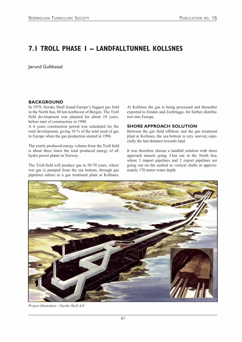
7/21/2019 Publication 16
http://slidepdf.com/reader/full/publication-16 69/181
NORWEGIAN T UNNELLING SOCIETY PUBLICATION NO . 16
67
7.1 TROLL PHASE 1 – LANDFALLTUNNEL KOLLSNES
Jørund Gullikstad
BACKGROUNDIn 1979, Norske Shell found Europe’s biggest gas fieldin the North Sea, 80 km northwest of Bergen. The Trollfield development was planned for about 10 years, before start of construction in 1990.A 6 years construction period was scheduled for thetotal development, giving 10 % of the total need of gasin Europe when the gas production started in 1996.
The yearly produced energy volume from the Troll fieldis about three times the total produced energy of allhydro power plants in Norway.
The Troll-field will produce gas in 50-70 years, wherewet gas is pumped from the sea bottom, through gas pipelines ashore to a gas treatment plant at Kollsnes.
At Kollsnes the gas is being processed and thereafterexported to Emden and Zeebrügge, for further distribu-tion into Europe.
SHORE APPROACH SOLUTIONBetween the gas field offshore and the gas treatment plant at Kollsnes, the sea bottom is very uneven, espe-cially the last distance towards land.
It was therefore chosen a landfall solution with shoreapproach tunnels going 4 km out in the North Sea,where 3 import pipelines and 2 export pipelines aregoing out on the seabed in vertical shafts at approxi-mately 170 meter water depth.
Project illustration - Norske Shell A/S

7/21/2019 Publication 16
http://slidepdf.com/reader/full/publication-16 70/181
NORWEGIAN T UNNELLING SOCIETY PUBLICATION NO . 16
68
An extreme challenge, giving both the Client and con-tractor challenges and limits not reached so far in thetunnelling history.
SHORE APPROACH TUNNELS
8 km of tunnels with cross-section between 50 and110 m2, was excavated in 21 months. The first 2 kmwas excavated with downhill 1:7 gradient. The rockwas composed of amphibolitic gneiss, including severaland difficult weakness zones containing active swell-ing clay. Many of these zones necessitated voluminousgrouting and rock support work.
Open zones was sealed with normal cement in combi-nation with mortars. Research work was performed tofind the optimum combination to seal off the most openfracture zones.Rock support was performed with systematic rock bolting, sprayed concrete and in a couple of zones fullconcrete lining was necessary.
The main tunnel has a low point approximately 250 meter below sea level and from there the tunnels continueupwards 1:100 ending in the piercing area 4 km out inthe North Sea. The last part of the tunnels was exca-vated in more migmatitic gneiss, with few weaknesszones and less need for rock support work. The tunnelsystem ends in three vertical shafts breaking the seabedat 157.5, 161 and 168.5 meter water depth.
PREPARATION WORK BEFORE SHAFTEXCAVATIONPrior to excavation of the vertical shafts, necessary preparation work was performed.A safety barrier of concrete was constructed in eachshaft tunnel to stop a potential uncontrolled in-leakageof water during shaft driving.
Further, seismic examination, systematic core drill-ing and grouting works were done in the shaft area toensure that the optimal location was found, to identifythe exact level and shape of the seabed and to avoid any
uncontrolled in-leak of water during drilling and blast-ing of shafts.
Finally, examination of existing overburden on the sea bottom was performed. It was observed that the thick-ness of soil sediments above rock head was up to 4meters. These sediments had to be removed to increasethe probability for successful shaft breakthrough and toavoid huge volume of sediments/clay to be stuck in theshafts after blasting of the tunnel piercings.
The removal of sediments was performed after groutingwork with a submersible vehicle called SEMI-2 having
12.000 HP propels. The vehicle removed rock up to 3tonnes from the sea bottom.
SHAFT EXCAVATION3 shafts with 35 m2 diameter and 25-35 meter lengthwere excavated with specially designed Alimak-equip-ment, until a piercing plug of 6-7 meters was remain-ing.
PREPARATION WORK AFTER SHAFTEXCAVATIONFollowing rock support in the shafts, a steel cone wasinstalled 20-30 meters above the tunnel floor. This steelcone was machined which chould be installed to matchthe riser bundle containing the gas pipelines, after thetunnel piercings were successfully completed. Eachsteel cone weighed approximately 17 tonnes, and wasinstalled with 2.5 mm accuracy using a specially con-structed winch and sheave system enabling the steel
cone to be installed without any persons in the shafts or below on the tunnel floor.
In addition, two steering constructions in steel wereinstalled above the steel cone to ensure the correct rota-tion of the riser bundles during installation.
Finally several concreting lines with special built con-crete locks were installed above the steel cone to resistthe forces from the final blast, and to enable concreting between the rock walls and riser bundles after instal-lation. The constructions in the shaft were designedto stay undamaged and resist the forces from the final
blasts containing approximately 1500 kg of explosives,thereafter followed by the rock masses going passed the
Piercing area - shaft excavation completed
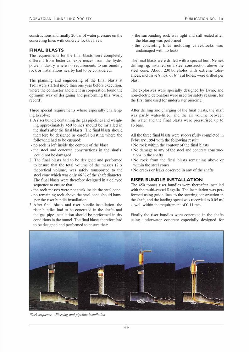
7/21/2019 Publication 16
http://slidepdf.com/reader/full/publication-16 71/181
NORWEGIAN T UNNELLING SOCIETY PUBLICATION NO . 16
69
constructions and finally 20 bar of water pressure on theconcreting lines with concrete locks/valves.
FINAL BLASTSThe requirements for the final blasts were completely
different from historical experiences from the hydro power industry where no requirements to surroundingrock or installations nearby had to be considered.
The planning and engineering of the final blasts atTroll were started more than one year before execution,where the contractor and client in cooperation found theoptimum way of designing and performing this ‘worldrecord’.
Three special requirements where especially challeng-ing to solve:1. A riser bundle containing the gas pipelines and weigh-
ing approximately 450 tonnes should be installed inthe shafts after the final blasts. The final blasts shouldtherefore be designed as careful blasting where thefollowing had to be ensured:
- no rock is left inside the contour of the blast - the steel and concrete constructions in the shafts
could not be damaged2. The final blasts had to be designed and performed
to ensure that the total volume of the masses (2 xtheoretical volume) was safely transported to thesteel cone which was only 46 % of the shaft diameter.The final blasts were therefore designed in a delayed
sequence to ensure that: - the rock masses were not stuck inside the steel cone - no remaining rock above the steel cone should ham-
per the riser bundle installation3. After final blasts and riser bundle installation, the
riser bundles had to be concreted in the shafts andthe gas pipe installation should be performed in dryconditions in the tunnel. The final blasts therefore hadto be designed and performed to ensure that:
- the surrounding rock was tight and still sealed afterthe blasting was performed
- the concreting lines including valves/locks wasundamaged with no leaks
The final blasts were drilled with a special built Nemekdrilling rig, installed on a steel construction above thesteel cone. About 230 boreholes with extreme toler-ances, inclusive 8 nos. of 6’’ cut holes, were drilled per blast.
The explosives were specially designed by Dyno, andnon-electric detonators were used for safety reasons, forthe first time used for underwater piercing.
After drilling and charging of the final blasts, the shaftwas partly water-filled, and the air volume betweenthe water and the final blasts were pressurised up to13 bars.
All the three final blasts were successfully completed inFebruary 1994 with the following result:• No rock within the contour of the final blasts• No damage to any of the steel and concrete construc-
tions in the shafts• No rock from the final blasts remaining above or
within the steel cones• No cracks or leaks observed in any of the shafts
RISER BUNDLE INSTALLATION
The 450 tonnes riser bundles were thereafter installedwith the multi-vessel Regalia. The installation was per-formed using guide lines to the steering construction inthe shaft, and the landing speed was recorded to 0.05 m/s, well within the requirement of 0.11 m/s.
Finally the riser bundles were concreted in the shaftsusing underwater concrete especially designed for
Work sequence - Piercing and pipeline installation
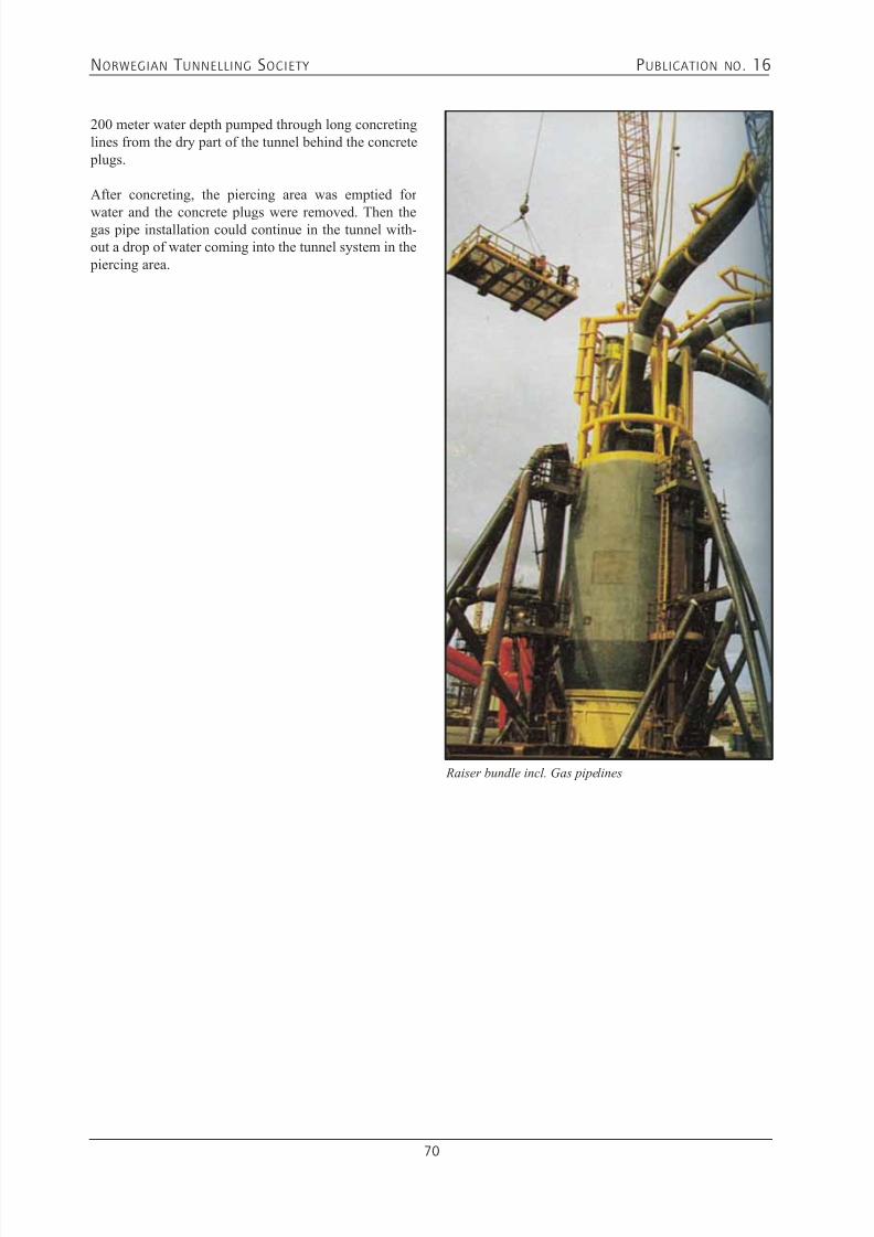
7/21/2019 Publication 16
http://slidepdf.com/reader/full/publication-16 72/181
NORWEGIAN T UNNELLING SOCIETY PUBLICATION NO . 16
70
200 meter water depth pumped through long concretinglines from the dry part of the tunnel behind the concrete plugs.
After concreting, the piercing area was emptied for
water and the concrete plugs were removed. Then thegas pipe installation could continue in the tunnel with-out a drop of water coming into the tunnel system in the piercing area.
Raiser bundle incl. Gas pipelines

7/21/2019 Publication 16
http://slidepdf.com/reader/full/publication-16 73/181
NORWEGIAN T UNNELLING SOCIETY PUBLICATION NO . 16
71
7.2 ÅSGARD TRANSPORTATION PROJECT
- KALSTØ LANDFALL - COMBINED TUNNEL AND BOREDSOLUTION
Jørund Gullikstad
Arild Palmstrøm
ABSTRACT:The gas from the Åsgard-field, 150 km northwest ofTrondheim out in the North Sea, is transported to
the terminal at Kårstø. From the Åsgard B platform,700 km of 42’’ gas pipeline is bringing the gas to thelandfall point at Kalstø. From Kalstø landfall the gasis following the 1.5 km existing Sleipner landfall tun-
nel, through Kalstø valve station, and 21 km further over land and fjords to Kårstø terminal. The paper describes two tunnelling milestones in sub-sea tunnel-ling that were achieved when the Kalstø landfall was
constructed in 1998:1. Excavation of a large sub-sea chamber with only 15
m to the sea bottom at 55 m water depth 2. Dry piercing to the sea bottom and pull-in of a pipe-
line without use of divers
INTRODUCTIONThrough the oil & gas period in Norway, several differ-ent landfall solutions have been performed:• For the Statpipe-lines to Kalstø, a prefabricated con-
crete culvert with huge amount of vessels and divers• For the Oseberg-pipeline towards Sture, a landfall
tunnel ending in a concreted pull-in chamber and final piercing to sea by blasting, the work in the chamberafter blasting was perfomed by divers
• For the Sleipner-pipeline to Kalstø, a landfall tunnel
with concreted pull-in chamber similar to Oseberg butwith a drilled solution instead of blasting, but still withuse of divers
• For the 5 Troll pipelines, vertical blasted piercingsfollowed by riser bundle installation, but for the firsttime without divers
• For the Heidrun-pipeline into Tjeldbergodden, anunderwater trench was the optimum solution all theway to the landfall area
Traditionally another landfall solution was selected onÅsgard. The method chosen was to utilise the existingthe Sleipner landfall tunnel, and from that use a drilledsolution to the flat sea bottom at about 60 meter water
depth approximately 1 km out in the North Sea. To avoiduse of divers, a seal tube was constructed to enable both
drilling and pull-in in dry and safe conditions.The offshore Åsgard oil and gas field is located Northwest of Trondheim. Gas from this field will be pumped through the 42” Åsgard Transport pipeline,which has a steel thickness of about 50 mm, to Statoil’sgas treatment plant at Kårstø. Here, natural gas will bestripped from the lean gas to bring the latter to salesspecification before it is sent to Emden in Germanythrough the Europipe II export line (Figure 1).
Figure 1: Overview (Palmstrøm, Skogheim 1999)

7/21/2019 Publication 16
http://slidepdf.com/reader/full/publication-16 74/181
NORWEGIAN T UNNELLING SOCIETY PUBLICATION NO . 16
72
Before arriving onshore from the North Sea the pipelineenters into an existing landfall tunnel at 60 m water depthto be protected from sea wave damage. This landfall tun-nel was constructed in 1990 - 92 for the Sleipner conden-
sate pipeline. It is 1350 m long with the deepest point 100m below sea level. In the first 300 m, the tunnel is 5.3 mwide; in the rest the span is 6.2 m, as shown on Figure 2.The rock cover (overburden) is 30 to 60 m.
The ground consists of gabbro, often metamorphosedto a gneissic rock. The rocks are generally moderately jointed with Q-value 4 – 25 (fair to good). A few largeweakness zones were encountered, having a quality Q= 0.01 to 1 (extremely to very poor). In addition, manysmall shears and minor weakness zones occur.
The rock support in the tunnel was tailored to the rockmass conditions encountered. No support was per-formed where few joints occurred, else the support wasshotcrete and fully grouted rock bolts. Concrete liningwas only applied at of the large weakness zone near thelow-point of the tunnel, making a total of 38 m, or 3 %of the tunnel length.
PREPARATION WORK BEFORE TUNNELEXTENSION WORK After completing the Sleipner condensate pipelineinstallation in 1992 the tunnel was flooded with seawater. Therefore, prior to commencing the work for
Åsgard in 1997 the existing Sleipner condensate landfalltunnel had to be dewatered for approximately 50 million
Figure 2: The conditions at the Kalstø landfall tunnel. (Palmstrøm, Skogheim 1999)
litres of water, and the necessary supplementary rocksupport performed.
Additional rock support, rock sealing and installation of
ventilation, light, water and high voltage electricity was performed in a few months time from February 1997.
TUNNEL EXTENSION WORK The tunnel extension work was especially challengingas the existing Sleipner condensate pipeline daily trans- ports condensate worth about 20 million NOK throughthe tunnel. A longer stop of the condensate transport toKårstø could in worst case stop the oil production at both Sleipner and Statfjord totally.
The extra piercing chamber had already been excavated
in 1991, see Figure 3. Some modifications in the land-fall tunnel and chamber had, however, to be made forthe installation of the Åsgard gas pipeline. This consist-ed of the excavation of 3500 m3 by drilling and blast-ing, partly performed as close as 5 m from the existingSleipner condensate pipeline, which was in operation.
The following preparation and protection work wastherefore performed before tunnel extension:• Mechanical impact from blasted rock was avoided
by installing New Jersey road blocks backfilled withabsorbable sorted fraction rock.
• In addition protective constructions using concrete and
timber were used in especially sensitive areas, prior tothe normal blasting mats and fibre mesh.

7/21/2019 Publication 16
http://slidepdf.com/reader/full/publication-16 75/181
NORWEGIAN T UNNELLING SOCIETY PUBLICATION NO . 16
73
• Blasting plans were carefully designed for each blastto accommodate strong vibration requirements. Thevibration velocity limit was set to 30 mm/s. During blasting, the vibrations on the condensate pipeline,surrounding rock and concrete foundations were close-
ly monitored. See Figure 3• In order to determine the drilling, charge and ignition plan a full-scale test-blasting program in the piercingchamber was carried out by using a similar protectedSleipner pipe, prior to start of extension work.
• Four alternative methods to take out the necessary rockvolume were evaluated: sawing, expansive cement,hydraulic splitting and pigging by hydraulic hammer.
• Other existing installations like electrical cables andsimilar were protected using split plastic pipes coveredwith sprayed concrete.
• An experienced engineering geologist from Norconsultclosely followed-up the tunnel works and the need forrock support and water sealing by grouting.
The existing Statpipe piercing chamber was enlargedto accommodate the pull-in of the Åsgard gas pipeline.Located at 60 m water depth with only 15 to 20 m rockcover, the chamber was widened from 8 m to 11 m span,and the height lifted from 7 to 9 m. The tunnel extensionwork using careful blasting was successfully completedwithout any damage to either permanent or temporaryinstallations.
Each blast was planned with a unique drilling pattern
and use of explosives. The drilling varied between 2 to4.5 drilled metres per m3 hard rock. Traditional explo-sives as dynamite, Dynotex 1, 2 and 4 were used, withan explosive quantity between 0.5 and 1 kg/m3. It wasalso restrictions on charges per interval, dependent upondistance to the existing Sleipner condensate pipeline.
The large dimensions of the piercing chamber and thewater depth caused extra challenges during the blasting,rock support and piercing works. The small rock coverof only 15 - 20 m resulted in low rock stresses, which
Figure 3: Left: Plan showing areas enlarged in the pull-in chamber from blasting. Right: Cross section of chamber.
(Palmstrøm, Skogheim 1999)
imposed an extra risk for joint opening and developmentof water leakage.
Upon completion of the rock blasting and rock supportworks, approximately 17 meter of rock was remaining
before the North Sea and the piercing operation couldstart.
PIERCING TO THE SEA BOTTOMPiercing of tunnels to the sea bed is not a new conceptin Norway. In connection with hydropower plants,some 600 - 700 of so-called “lake taps” or “bottom piercings” have been used [3 to 6]. For the landing of pipelines from the North Sea, this vast experience has been utilised.
A main goal for landing of the Åsgard gas pipeline wasto pull in the pipeline without use of divers.
PreparationsThe piercing was performed using a well planned drill-ing and reaming procedure. The client, Statoil, deter-mined the specifications and the method to be applied,while the contractor, AF Spesialprosjekt, was respon-sible for the planning and performance of the works incompliance with the strict specifications, both to HSEand QA/QC. For this, AF Spesialprosjekt had experi-ence from similar operations, among others for the TrollPhase I Project in 1991-1995, comprising 3 piercings at160 – 170 m water depth [7, 8].
A special steel structure, the so-called seal tube system(ESD-valve, pipe receiver, stripper valves, drill string bearings, flushing system etc.) was developed and deliv-ered by Statoil to provide a “dry” piercing and pull-inoperation into the piercing chamber.
After piercing, the rock face had been reinforced withrock bolts and shotcrete, the following works were performed:1. Drilling of several probe holes to check the distance

7/21/2019 Publication 16
http://slidepdf.com/reader/full/publication-16 76/181
NORWEGIAN T UNNELLING SOCIETY PUBLICATION NO . 16
74
to the sea, and to collect information about the rockquality and water leakage conditions.
2. Rock grouting/injection of the rock masses in the piercing area to prevent potential water leakage.
3. Rock mass reinforcement by fully grouted rock bolts
in a pattern adjacent to the planned piercing hole.4. Blasting of a 2.2 m diameter and 4 m deep “cylinder”along the piercing hole centreline for seal tube systemanchoring purposes.
5. Drilling of grouting, casting and sea water holes forfuture casting around the Åsgard pipeline.
6. Installation of the seal tube system with: • Anchoring systems (casting and rock bolts). • Mechanical installation (steel structures, pumps,
valves, computer systems, hydraulic systems, etc.).• Testing and commissioning.
After extensive grouting works the water leakage intothe piercing chamber was reduced to 30 l/min.
Figure 4: Layout of the piercing with the small pilot hole
(made by directional drilling). The cementing holes were
used for filling cement grout around the pipeline in the pierc-
ing hole after pull-in. (Palmstrøm, Skogheim 1999)
Drilling of the piercing hole and pull in of the 42”Åsgard gas pipelineThe piercing operation can be divided into the followingsteps, as shown in Figures 4 and 5:• Directional core drilling of the first 56mm diameter
pilot hole until 3 metres from the sea bed. The holewas then enlarged to 76 mm diameter using a standardcore drilling rig.
• Installation of the seal tube system, which wasanchored to the rock face.
• Installation of a drill rig behind the seal tube systemfor reaming of the pilot hole
• Reaming of the 76 mm hole to 308 mm (12¼”) diam-eter including drilling of the remaining 3 m to theseabed.
• Drill string was then disconnected from drilling rig andthe messenger wire attached to the drill string. Marinevessel (DSV) pulled the drill string with messenger
wire attached out of the piercing hole and up to onthe vessels deck. A new drill string with the Ø1.6 m
reamer head was then connected to the Ø30 mm mes-senger wire and lowered down to the sea bed.
• The drill string was then pulled into the 12¼” pilothole and the reaming of the 1.6 m diameter boreholestarted from the sea towards the seal tube. Initially,
the reaming was performed very carefully to minimisevibrations from the drill string/reamer head. Drillingdebris/cutting ships were continuously removed by awater jet system installed behind the reamer head. SeeFigure 6.
• Upon completion of the bore hole, the drill string andmessenger wire were pushed/pulled out and hoistedwith air bags onboard to the DSV.
• The Ø90 mm pull-in wire was then attached to themessenger wire and pulled into piercing chamber viathe seal tube system and finally connected to the 500tonnes linear winching system, which was installed inthe same position as the drilling rig was in the previ-ous operation.
Final Pull-InROVs (remotely operated vehicles) equipped with videocameras were used for all sub sea works (connections,inspections, etc.). All sub sea activities was closelymonitored in the observation/control centre via TV-linksand UHF radio communication (land – sea – tunnel).
In May 1998, one of the world’s biggest pipeline instal-lation vessels - LB200, arrived at Kalstø.
Pipeline production starts onboard the magnificent ves-sel immediately after arrival.
In close communication between the control room atKalstø, the control room at LB200 and the operationalresources in the tunnel, the 42’’ Åsgard pipeline is safelyinstalled into the Kalstø seal tube, see Figure 6.
After the pull-in, the Åsgard pipeline was anchored torock by grouting between the pipeline and the Ø1.6 m piercing borehole walls by using the pre-drilled concret-ing and injection holes.
After a few days curing, the seal tube was disman-tled, and the 42’’ Åsgard pipeline showed to be safelyanchored with no water leaks into the tunnel, ready forfurther pipe installation towards Kårstø.All the challenges in this complex project were solvedand accomplished according to schedule and givenspecifications, thanks to well-planned preparations andgreat achievements from all parties involved.

7/21/2019 Publication 16
http://slidepdf.com/reader/full/publication-16 77/181
NORWEGIAN T UNNELLING SOCIETY PUBLICATION NO . 16
75
Figure 5: After the pilot hole had been drilled, the reamer
was pulled into the hole. (Palmstrøm, Skogheim 1999)
Figure 6: The reaming of the pilot hole and the later pull-in
of the pipeline. (Palmstrøm, Skogheim 1999)
REFERENCES[1] Gullikstad J. (1998): Åsgard landfall, challenges at60 m depth. (in Norwegian)Proc. Fjellsprengnings-konferansen (National annualtunnelling conference) 1998, 10 p.
[2] Fuhre B. (1998): Landing of gas from Åsgard withnew technology. (in Norwegian) Byggeindustrien, No.4, pp. 6 - 10.
[3] Stormo Ø. H. (1981): Successful piercing at 85 mdepth. (in Norwegian)Bygg, Bd 29, No 1, 2 p.
[4] Solvik Ø. (1984): Underwater piercing of a tunnel.Water Power & Dam Construction, November 1984, pp. 33-36.
[5] Berdal B., Buen B. and Johansen J. (1985): Lake tap – the Norwegian method.Proc. Tunnelling ’85, 5 p.
[6] Hoel S. (1987): Works for the piercing at Sture. (in Norwegian)Proc. Fjellsprengnings-konferansen 1987, 4 p.
[7] Robstad E. (1992): Requirements to quality and safe-ty for the Troll shore approach tunnels. (in Norwegian)Proc. Fjellsprengningskonferansen 1992, 16 p.
[8] Klüver H. (1991: Troll phase 1 – shore approachtunnels. (in Norwegian)Proc. Fjellsprengningskonferansen 1992, 12 p.
[9] Palmstrøm A. and Skogheim A. (1999: NewMilestones in Subsea Blasting at Water Depth of 55m.Tunnelling and Underground Space Technology, Vol.15, No. 1, 1999, pp. 65 – 69
7/21/2019 Publication 16
http://slidepdf.com/reader/full/publication-16 78/181
NORWEGIAN T UNNELLING SOCIETY PUBLICATION NO . 16
76

7/21/2019 Publication 16
http://slidepdf.com/reader/full/publication-16 79/181
NORWEGIAN T UNNELLING SOCIETY PUBLICATION NO . 16
77
7.3 KVITEBJØRN RICH GAS PIPELINE PROJECT
KOLLSNES LANDFALL - TUNNEL SHORE APPROACHArild Neby
Thomas K. Mathiesen
ABSTRACT: Pipelines from offshore oil and gas fields in the NorthSea are serving several onshore process plants on the
Norwegian west coast. The shore approach itself is normally a challenge as the subsea topography off the coast is rugged and seldom facilitates landfall siteswith gently sloping sandy beaches coming up from the
continental shelf and slope. Large diameter bore holes drilled from within the process plant area through the rocky barrier and out in the sea have been a common solution for landing pipelines where other methods have not been available. The bored solutions have however often proved to be expensive.
For the Kvitebjørn Rich Gas Pipeline the conceptual solution was a bored landfall with an optional tunnel
solution alternative. During the detail design phase a feasibility study on a tunnelled solution combined withunderwater tunnel piercing techniques, adapted from
the hydropower civil works sector, revealed that for this project the tunnel solution was feasible. Bids were made to both solutions and after evaluation of bids itwas recommended to go ahead with the tunnel alter-
native based on an evaluation of economy, technical aspects and HSE. The Kvitebjørn Landfall tunnel was constructed in 4 months during the summer of 2002.
INTRODUCTION
The Kvitebjørn gas and condensate field lies in block34/11, east of Gullfaks in the Norwegian North Sea,operated by Statoil. Production from Kvitebjørn beganin 2004. Rich gas and condensate (light oil) fromKvitebjørn are piped to Kollsnes near Bergen andMongstad further north respectively.
Rich gas from Kvitebjørn is piped in the 147 km longOD 30’’ (Ø762 mm) Kvitebjørn Rich Gas Pipeline(KGR) to the process plant at Kollsnes (see Figure 1).After processing at Kollsnes, the dry gas is piped tocontinental Europe. The separated NGL is transported by pipeline to the Vestprosess plant at Mongstad for
fractionation into propane, butanes and naphtha.
Condensate travels through the Kvitebjørn Oil Pipeline(KOR), which ties into the Troll Oil Pipeline II toMongstad (see Figure 1). Based on current plans it isexpected to recover roughly 55 billion cubic metres ofgas and 22 million cubic metres of condensate.
The partners in the license are: Statoil ASA (43.55%),Petoro AS (30%), Norsk Hydro Produksjon a.s (15%), TotalE&P Norge AS (5%) and Enterprise Oil Norge AS (6.45%)
The article covers the civil aspects of the detail designand construction of the landfall tunnel section atKollsnes as well as going briefly into the conceptualdesign discussions.
The Kvitebjørn Landfall tunnel was constructed during
the period May - September 2002. The drill and blasttunnelling works commenced on 21 May 2002. Final piercing at depth -66 m was executed 12 September2002. The civil works part of the project was cost esti-mated to approximately NOK 25 million.
The pipeline was pulled in through the landfall tunnel toKollsnes on 15 May 2003. Production from Kvitebjørn began on 26 September 2004. The field began deliver-ing natural gas through the pipeline on 1 October 2004.
Figure 1: Map showing Kvitebjørn Pipelines
(Illustration: Statoil)
Gas Pipeline (KGR)
Oil Pipeline (KOR
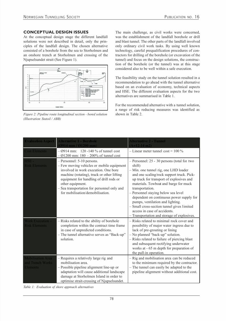
7/21/2019 Publication 16
http://slidepdf.com/reader/full/publication-16 80/181
NORWEGIAN T UNNELLING SOCIETY PUBLICATION NO . 16
78
CONCEPTUAL DESIGN ISSUESAt the conceptual design stage the different landfallsolutions were not described in detail, only the prin-ciples of the landfall design. The chosen alternativeconsisted of a borehole from the sea to Storholmen and
an onshore trench at Storholmen and crossing of the Njupselsundet strait (See Figure 1).
Figure 2: Pipeline route longitudinal section - bored solution
(Illustration: Statoil / ABB)
The main challenge, as civil works were concerned,was the establishment of the landfall borehole or drilland blast tunnel. The other parts of the landfall involvedonly ordinary civil work tasks. By using well knowntechnology, careful prequalification procedures of con-
tractors for drilling of the borehole (or excavation of thetunnel) and focus on the design solutions, the construc-tion of the borehole (or the tunnel) was at this stageconsidered also to be well within a safe execution.
The feasibility study on the tunnel solution resulted in arecommendation to go ahead with the tunnel alternative based on an evaluation of economy, technical aspectsand HSE. The different evaluation aspects for the twoalternatives are summarised in Table 1.
For the recommended alternative with a tunnel solution,a range of risk reducing measures was identified asshown in Table 2.
Evaluation Aspect Alternative 1 - Borehole(Ø914 mm / Ø1200 mm)
Alternative 2 - Tunnel(A=12-14 m2)
Cost Elements – Ø914 mm: 120 -140 % of tunnel cost – Ø1200 mm: 180 – 200% of tunnel cost
– Linear meter tunnel cost = 100 %
HSE -Risk Elements
– Personnel: 5-10 persons. – Few moving vehicles or mobile equipment
involved in work execution. One boremachine (rotating), truck or other liftingequipment for handling of drill rods orother equipment.
– Sea transportation for personnel only andfor mobilisation/demobilisation.
– Personnel: 25 - 30 persons (total for twoshift)
– Min. one tunnel rig, one LHD loaderand one scaling/rock support truck. Pick-up truck for transport of explosives andmaterials. Towboat and barge for mucktransportation.
– Personnel staying below sea leveldependent on continuous power supply for pumps, ventilation and lighting.
– Small cross-section tunnel gives limitedaccess in case of accidents.
– Transportation and storage of explosives.
Work Execution -
Risk Elements
– Risks related to the ability of borehole
completion within the contract time framein case of unpredicted conditions.
– The tunnel alternative serves as “Back-up”solution.
– Risks related to minimal rock cover and
possibility of major water ingress due tolack of pre-grouting or lining
– No planned “back-up” solution. – Risks related to failure of piercing blast
and subsequent rectifying underwaterworks at - 65 m depth for preparation ofthe pull-in operation.
Mobilisation Areaand Trench WorksElements
– Requires a relatively large rig andmobilisation area.
– Possible pipeline alignment line-up oradaptation will cause additional landscapedamage at Storholmen Island in order to
optimise strait-crossing of Njupselsundet.
– Rig and mobilisation area can be reducedto the minimum required by the contractor.
– The tunnel can easily be adapted to the pipeline alignment without additional cost.
Table 1: Evaluation of shore approach alternatives
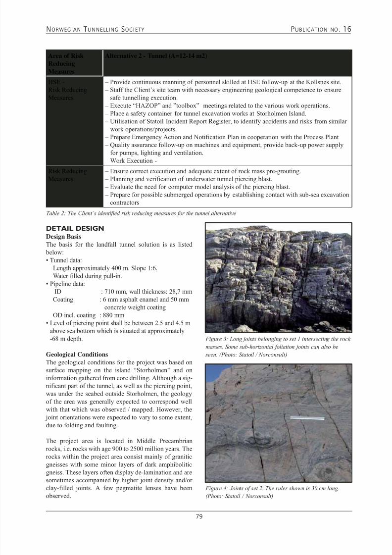
7/21/2019 Publication 16
http://slidepdf.com/reader/full/publication-16 81/181
NORWEGIAN T UNNELLING SOCIETY PUBLICATION NO . 16
79
Area of RiskReducingMeasures
Alternative 2 - Tunnel (A=12-14 m2)
HSE -Risk Reducing
Measures
– Provide continuous manning of personnel skilled at HSE follow-up at the Kollsnes site. – Staff the Client’s site team with necessary engineering geological competence to ensure
safe tunnelling execution. – Execute “HAZOP” and ”toolbox” meetings related to the various work operations. – Place a safety container for tunnel excavation works at Storholmen Island. – Utilisation of Statoil Incident Report Register, to identify accidents and risks from similar
work operations/projects. – Prepare Emergency Action and Notification Plan in cooperation with the Process Plant – Quality assurance follow-up on machines and equipment, provide back-up power supply
for pumps, lighting and ventilation.Work Execution -
Risk ReducingMeasures
– Ensure correct execution and adequate extent of rock mass pre-grouting. – Planning and verification of underwater tunnel piercing blast. – Evaluate the need for computer model analysis of the piercing blast.
– Prepare for possible submerged operations by establishing contact with sub-sea excavationcontractors
Table 2: The Client’s identified risk reducing measures for the tunnel alternative
DETAIL DESIGNDesign BasisThe basis for the landfall tunnel solution is as listed below:• Tunnel data: Length approximately 400 m. Slope 1:6. Water filled during pull-in.• Pipeline data:
ID : 710 mm, wall thickness: 28,7 mm Coating : 6 mm asphalt enamel and 50 mm
concrete weight coating OD incl. coating : 880 mm• Level of piercing point shall be between 2.5 and 4.5 m
above sea bottom which is situated at approximately-68 m depth.
Geological ConditionsThe geological conditions for the project was based onsurface mapping on the island “Storholmen” and oninformation gathered from core drilling. Although a sig-
nificant part of the tunnel, as well as the piercing point,was under the seabed outside Storholmen, the geologyof the area was generally expected to correspond wellwith that which was observed / mapped. However, the joint orientations were expected to vary to some extent,due to folding and faulting.
The project area is located in Middle Precambrianrocks, i.e. rocks with age 900 to 2500 million years. Therocks within the project area consist mainly of graniticgneisses with some minor layers of dark amphiboliticgneiss. These layers often display de-lamination and aresometimes accompanied by higher joint density and/or
clay-filled joints. A few pegmatite lenses have beenobserved.
Figure 3: Long joints belonging to set 1 intersecting the rock
masses. Some sub-horizontal foliation joints can also be
seen. (Photo: Statoil / Norconsult)
Figure 4: Joints of set 2. The ruler shown is 30 cm long.
(Photo: Statoil / Norconsult)

7/21/2019 Publication 16
http://slidepdf.com/reader/full/publication-16 82/181
NORWEGIAN T UNNELLING SOCIETY PUBLICATION NO . 16
80
The foliation of the gneiss strikes generally NE-SWwith a gentle dip (0° - 15°) towards SE. Joints alongthe foliation form the main joint set 1 with joint spacingmainly between 0.2 and 2 metres.
The two other joint sets are steep-dipping and occurapproximately normal to joint set 1.
Set 2 with strike/dip = 140 - 170°/80 - 90º E, jointspacing 0.3 - 3 m, and
Set 3 having strike/dip = 30 - 50º /90º and joint spacing0.2 - 3 m.
The joints occur unevenly distributed, in some areasonly one joint set occurs, in others all three sets. In gen-eral, the joints divide the rocks into blocks, which vary between 0.1 m³ and 3 m³. Most joints have rough jointsurface with slightly undulating joint planes.
Figure 5: Engineering geological map showing pipeline route and location of core-drilled hole. (Illustration: Norconsult)
Locally, the joints in sets 2 and 3 have only 0.02 - 0.2 mspacing forming joint zones. The width of such zones ismost often 0.2 - 3 m. In some zones the spacing betweenthe joints is so short that the zone may have the charac-ter of a crushed zone.
The identified weakness zones generally follow thedirection of the two steep-dipping joint sets.
Generally the geological conditions were found to berelatively good, and hence, favourable for a sub-seatunnel. Uncertainty regarding permeability of the rockmass, especially in the piercing area, was to be givenspecial attention during construction phase. Thoroughand continuous routines for exploratory drilling andgrouting, throughout the entire excavation period of thelandfall tunnel as well as at the piercing itself, were a prerequisite.

7/21/2019 Publication 16
http://slidepdf.com/reader/full/publication-16 83/181
NORWEGIAN T UNNELLING SOCIETY PUBLICATION NO . 16
81
Figure 6: Stereographic pole-plot from joint mapping at Storholmen. The different poles are denoted as follows: F = foliation;
J = joint sets; W = weakness zones/faults. The great circles illustrate the average strike and dip of the three main joint sets.
(Illustration: Norconsult)
LANDFALL TUNNEL DESIGNTunnel longitudinal sectionThe topography dictates the geometrical constraintsfor tunnel alignment. As the location of the piercing point must be aligned with the pipeline in the tunnel
and the piercing point has to be just above the sea bot-tom sediments, as well as the tunnel should start at anelevation safe from spring tide sea level, - the straightline between these geometrical “fix points” has a gradeapproximately 1:6. Excavating the tunnel at a steeper
Figure 7: Longitudinal section and plan of landfall tunnel. (Illustration: Statoil / Norconsult)
decline was possible but not found to be beneficial tothe project.According to refraction seismic surveys performed in1990, the rock mass in the area of the sub-sea tunnel isgenerally good. However, the maximum rock overbur-
den in the sub-sea part of the tunnel is about 26 m, anda significant length of the tunnel will be excavated withrock overburden less than 15 m, see Figure 7. This isless than a normally used criterion for sub-sea tunnel-ling.
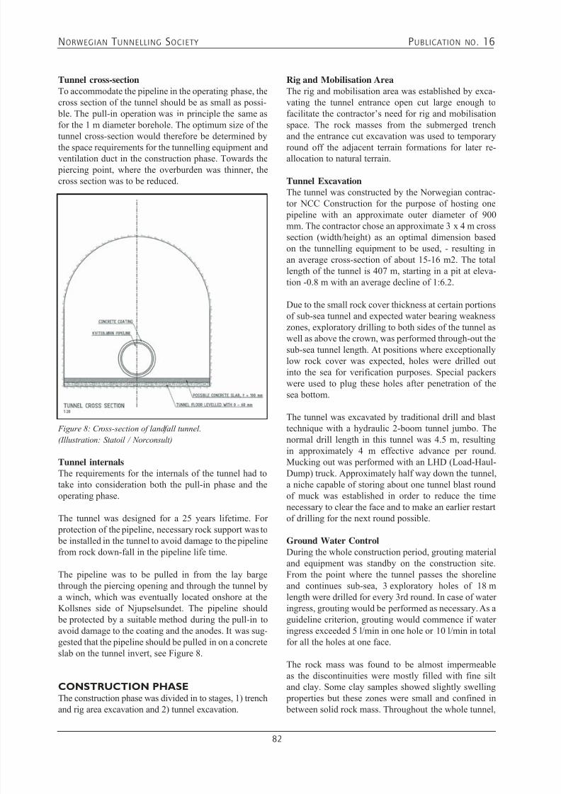
7/21/2019 Publication 16
http://slidepdf.com/reader/full/publication-16 84/181
NORWEGIAN T UNNELLING SOCIETY PUBLICATION NO . 16
82
Tunnel cross-sectionTo accommodate the pipeline in the operating phase, thecross section of the tunnel should be as small as possi- ble. The pull-in operation was in principle the same asfor the 1 m diameter borehole. The optimum size of the
tunnel cross-section would therefore be determined bythe space requirements for the tunnelling equipment andventilation duct in the construction phase. Towards the piercing point, where the overburden was thinner, thecross section was to be reduced.
Figure 8: Cross-section of landfall tunnel.
(Illustration: Statoil / Norconsult)
Tunnel internalsThe requirements for the internals of the tunnel had totake into consideration both the pull-in phase and theoperating phase.
The tunnel was designed for a 25 years lifetime. For protection of the pipeline, necessary rock support was to be installed in the tunnel to avoid damage to the pipeline
from rock down-fall in the pipeline life time.
The pipeline was to be pulled in from the lay bargethrough the piercing opening and through the tunnel bya winch, which was eventually located onshore at theKollsnes side of Njupselsundet. The pipeline should be protected by a suitable method during the pull-in toavoid damage to the coating and the anodes. It was sug-gested that the pipeline should be pulled in on a concreteslab on the tunnel invert, see Figure 8.
CONSTRUCTION PHASE
The construction phase was divided in to stages, 1) trenchand rig area excavation and 2) tunnel excavation.
Rig and Mobilisation AreaThe rig and mobilisation area was established by exca-vating the tunnel entrance open cut large enough tofacilitate the contractor’s need for rig and mobilisationspace. The rock masses from the submerged trench
and the entrance cut excavation was used to temporaryround off the adjacent terrain formations for later re-allocation to natural terrain.
Tunnel ExcavationThe tunnel was constructed by the Norwegian contrac-tor NCC Construction for the purpose of hosting one pipeline with an approximate outer diameter of 900mm. The contractor chose an approximate 3 x 4 m crosssection (width/height) as an optimal dimension basedon the tunnelling equipment to be used, - resulting inan average cross-section of about 15-16 m2. The totallength of the tunnel is 407 m, starting in a pit at eleva-tion -0.8 m with an average decline of 1:6.2.
Due to the small rock cover thickness at certain portionsof sub-sea tunnel and expected water bearing weaknesszones, exploratory drilling to both sides of the tunnel aswell as above the crown, was performed through-out thesub-sea tunnel length. At positions where exceptionallylow rock cover was expected, holes were drilled outinto the sea for verification purposes. Special packerswere used to plug these holes after penetration of thesea bottom.
The tunnel was excavated by traditional drill and blasttechnique with a hydraulic 2-boom tunnel jumbo. Thenormal drill length in this tunnel was 4.5 m, resultingin approximately 4 m effective advance per round.Mucking out was performed with an LHD (Load-Haul-Dump) truck. Approximately half way down the tunnel,a niche capable of storing about one tunnel blast roundof muck was established in order to reduce the timenecessary to clear the face and to make an earlier restartof drilling for the next round possible. Ground Water Control
During the whole construction period, grouting materialand equipment was standby on the construction site.From the point where the tunnel passes the shorelineand continues sub-sea, 3 exploratory holes of 18 mlength were drilled for every 3rd round. In case of wateringress, grouting would be performed as necessary. As aguideline criterion, grouting would commence if wateringress exceeded 5 l/min in one hole or 10 l/min in totalfor all the holes at one face.
The rock mass was found to be almost impermeableas the discontinuities were mostly filled with fine siltand clay. Some clay samples showed slightly swelling
properties but these zones were small and confined in between solid rock mass. Throughout the whole tunnel,
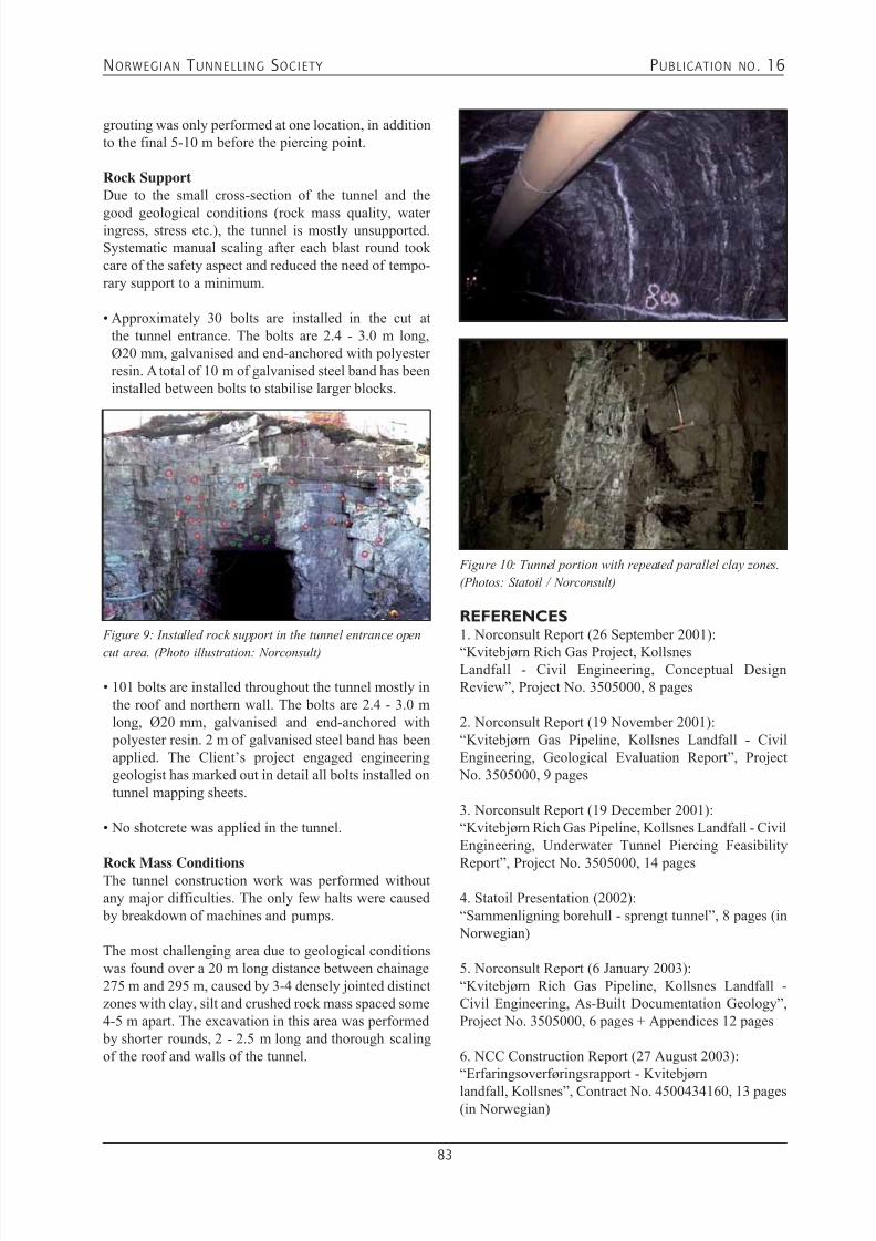
7/21/2019 Publication 16
http://slidepdf.com/reader/full/publication-16 85/181
NORWEGIAN T UNNELLING SOCIETY PUBLICATION NO . 16
83
grouting was only performed at one location, in additionto the final 5-10 m before the piercing point.
Rock SupportDue to the small cross-section of the tunnel and the
good geological conditions (rock mass quality, wateringress, stress etc.), the tunnel is mostly unsupported.Systematic manual scaling after each blast round tookcare of the safety aspect and reduced the need of tempo-rary support to a minimum.
• Approximately 30 bolts are installed in the cut atthe tunnel entrance. The bolts are 2.4 - 3.0 m long,Ø20 mm, galvanised and end-anchored with polyesterresin. A total of 10 m of galvanised steel band has beeninstalled between bolts to stabilise larger blocks.
Figure 9: Installed rock support in the tunnel entrance open
cut area. (Photo illustration: Norconsult)
• 101 bolts are installed throughout the tunnel mostly inthe roof and northern wall. The bolts are 2.4 - 3.0 mlong, Ø20 mm, galvanised and end-anchored with polyester resin. 2 m of galvanised steel band has beenapplied. The Client’s project engaged engineeringgeologist has marked out in detail all bolts installed ontunnel mapping sheets.
• No shotcrete was applied in the tunnel.
Rock Mass ConditionsThe tunnel construction work was performed withoutany major difficulties. The only few halts were caused by breakdown of machines and pumps.
The most challenging area due to geological conditionswas found over a 20 m long distance between chainage275 m and 295 m, caused by 3-4 densely jointed distinctzones with clay, silt and crushed rock mass spaced some4-5 m apart. The excavation in this area was performed by shorter rounds, 2 - 2.5 m long and thorough scalingof the roof and walls of the tunnel.
Figure 10: Tunnel portion with repeated parallel clay zones.
(Photos: Statoil / Norconsult)
REFERENCES1. Norconsult Report (26 September 2001):
“Kvitebjørn Rich Gas Project, KollsnesLandfall - Civil Engineering, Conceptual DesignReview”, Project No. 3505000, 8 pages
2. Norconsult Report (19 November 2001):“Kvitebjørn Gas Pipeline, Kollsnes Landfall - CivilEngineering, Geological Evaluation Report”, Project No. 3505000, 9 pages
3. Norconsult Report (19 December 2001):“Kvitebjørn Rich Gas Pipeline, Kollsnes Landfall - CivilEngineering, Underwater Tunnel Piercing Feasibility
Report”, Project No. 3505000, 14 pages
4. Statoil Presentation (2002):“Sammenligning borehull - sprengt tunnel”, 8 pages (in Norwegian)
5. Norconsult Report (6 January 2003):“Kvitebjørn Rich Gas Pipeline, Kollsnes Landfall -Civil Engineering, As-Built Documentation Geology”,Project No. 3505000, 6 pages + Appendices 12 pages
6. NCC Construction Report (27 August 2003):“Erfaringsoverføringsrapport - Kvitebjørn
landfall, Kollsnes”, Contract No. 4500434160, 13 pages(in Norwegian)

7/21/2019 Publication 16
http://slidepdf.com/reader/full/publication-16 86/181
NORWEGIAN T UNNELLING SOCIETY PUBLICATION NO . 16
84
Research, development
and consulting
NGI has competence withingeotechnics, rock engineering, rock
mass classification, undergroundsupport design, hydrogeology and
environmental geotechnology.NGI's expertise is within materialproperties, modelling and analysis, and
instrumentation and monitoring.
NGI serves the followingsectors:
Oil, gas and energyTransportation
Natural hazardsBuilding and construction
Environmental engineering
Norwegian Geotechnical InstituteSognsveien 72, P.O.Box 3930 Ullevaal Stadion, N-0806 Oslo, Norway
Telephone: +47 22 02 30 00 – Telefax: +47 22 23 04 48e-mail: [email protected] – http://www.ngi.no

7/21/2019 Publication 16
http://slidepdf.com/reader/full/publication-16 87/181
NORWEGIAN T UNNELLING SOCIETY PUBLICATION NO . 16
85
8.1 UNDERWATER TUNNEL PIERCING
A NORWEGIAN SPECIALITY DURING THE LAST 100 YEARSØyvind Solvik
Underwater piercing of tunnels was generally connectedto development of hydroelectric power schemes withthe intention of utilizing the potential of lake reservoirs beneath the natural outlet for power production. Suchtunnel piercing has been carried out for 100 years, butnot exclusively connected to hydroelectric power devel-opment. Nevertheless, the first underwater piercingin Norway was the lowering of the Lake Demmevatnlocated on the west side of Hardangerjøkelen in southwest Norway. In this particular case a glacier dammedup the Lake Demmevatn serving as a particular unreli-able weir that could break through any time and causeuncontrolled destruction to the valley Simadalen beinglocated downstream the lake. A tunnel was excavated below the bottom of the lake and the piercing was per-formed at 20 meters water depth.
During the first half of the 20th century a great numberof underwater tunnel piercings were carried out atmoderate water depth in connection with hydroelectric power development, and in the years before the lastworld war some hundred underwater piercing werealready completed. There is little information about themethods that were used at that time and how successfulthese piercing blasts were. It is assumed that the con-tractors had their own procedures of execution and thatlimited documentation existed, but some times a combi-nation of good luck and good management prevailed. If
something went wrong, the job was often completed inthe best possible way without any particular publishingor documentation of something that might be consid-ered a blunder. The worst case for a contractor was anunsuccessful final blast without achieving a successful break-through. It was considered a major risk to order people to enter the tunnel face as it could not be grantedthat the water would not break through, which would be a disaster. There are good reasons to presume that the previousinvestigations regarding rock mechanical and geologi-cal aspects were less comprehensive than the require-
ment of today when designing an underwater piercing.Some times serious landslides took place especially in
places where marine clay appeared. In one particular caseincluding marine clay it was suggested that the compensa-tion cost for damages caused by an underwater landslideamounted to the same cost as the constructional cost.
In this period the development of hydroelectric powerschemes comprised mostly of medium to small power plants and although such damage cost could cause con-siderable financial deficit to anyone single hydroelectric power project, such incidents may not have an effect tothe national economy. It was generally acknowledgedthat such underwater tunnel piercings provided a costeffective utilisation of the water reservoir in most cases.The method became internationally known as “The Norwegian Method”.
The rebuilding of Norway following the last worldwar involved a particular focus on hydroelectric powerdevelopment, which also called for an optimum exploi-tation of draw down reservoirs. The submerged tunnel piercing became more difficult as the limits of experi-ence were exceeded. Some unsuccessful cases made itclear that the physical processes involved in the pierc-ing were not fully understood and this called for moreresearch work. SINTEF-NHL had the capacity andcompetence to address the problems appropriately atthe hydro-technical laboratory in Trondheim which wasreputed for its problem solving ability associated with
the development of hydroelectric power. By means ofscaled model testing it was now possible to study theflow conditions inside the tunnel during the blasting process and if necessary introduce improvements to thedesign. The first physical model test was done in the beginning of the 1960`s and marked the commencementof a research programme that was carried out duringseveral decades along with the most active years of thehydroelectric power development in Norway.
As a result of this comprehensive research, it is justifiedto say that today knowledge exists on how to work outthe design for underwater tunnel piercing and execute
the blast in a successful manner, also with water depthwhich earlier was classified as a hazard.
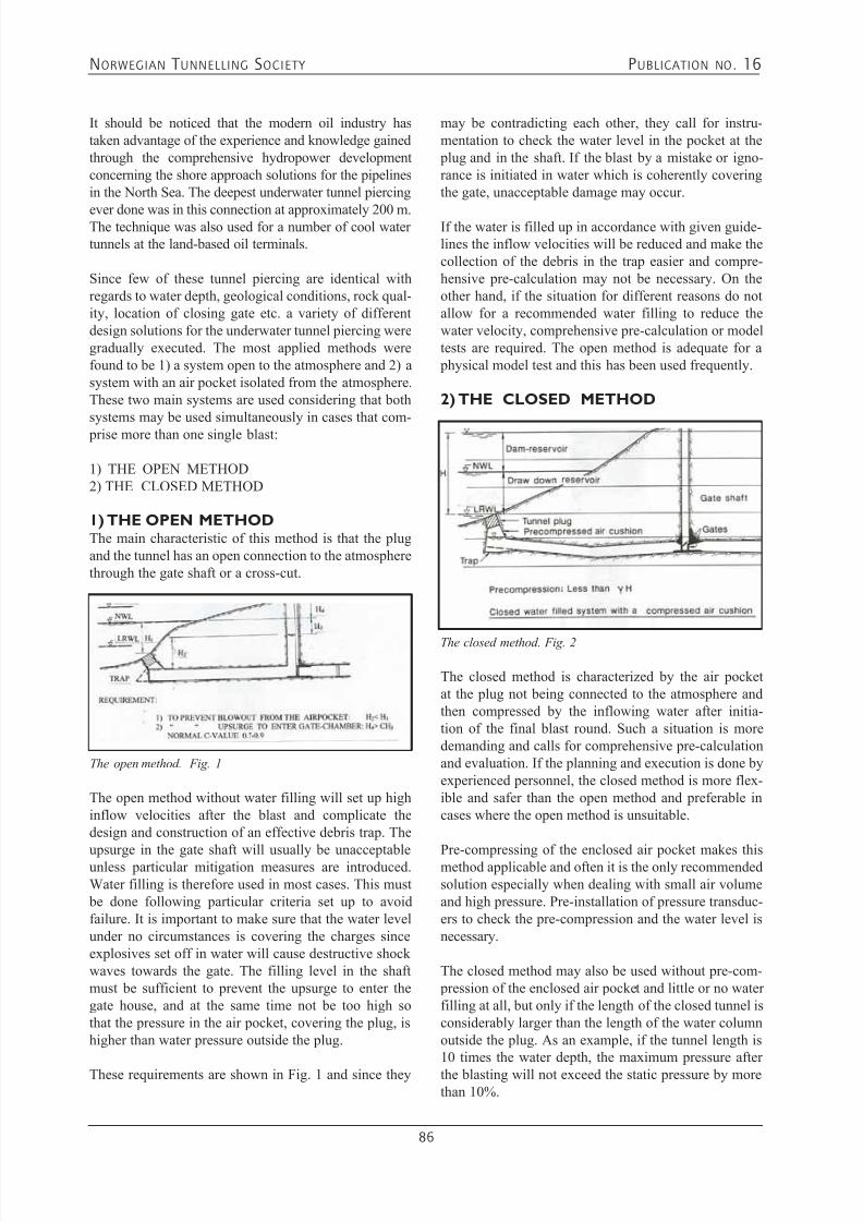
7/21/2019 Publication 16
http://slidepdf.com/reader/full/publication-16 88/181
NORWEGIAN T UNNELLING SOCIETY PUBLICATION NO . 16
86
It should be noticed that the modern oil industry hastaken advantage of the experience and knowledge gainedthrough the comprehensive hydropower developmentconcerning the shore approach solutions for the pipelinesin the North Sea. The deepest underwater tunnel piercing
ever done was in this connection at approximately 200 m.The technique was also used for a number of cool watertunnels at the land-based oil terminals.
Since few of these tunnel piercing are identical withregards to water depth, geological conditions, rock qual-ity, location of closing gate etc. a variety of differentdesign solutions for the underwater tunnel piercing weregradually executed. The most applied methods werefound to be 1) a system open to the atmosphere and 2) asystem with an air pocket isolated from the atmosphere.These two main systems are used considering that bothsystems may be used simultaneously in cases that com- prise more than one single blast:
1) THE OPEN METHOD2) THE CLOSED METHOD
1) THE OPEN METHODThe main characteristic of this method is that the plugand the tunnel has an open connection to the atmospherethrough the gate shaft or a cross-cut.
The open method without water filling will set up highinflow velocities after the blast and complicate thedesign and construction of an effective debris trap. The
upsurge in the gate shaft will usually be unacceptableunless particular mitigation measures are introduced.Water filling is therefore used in most cases. This must be done following particular criteria set up to avoidfailure. It is important to make sure that the water levelunder no circumstances is covering the charges sinceexplosives set off in water will cause destructive shockwaves towards the gate. The filling level in the shaftmust be sufficient to prevent the upsurge to enter thegate house, and at the same time not be too high sothat the pressure in the air pocket, covering the plug, ishigher than water pressure outside the plug.
These requirements are shown in Fig. 1 and since they
The open method. Fig. 1
may be contradicting each other, they call for instru-mentation to check the water level in the pocket at the plug and in the shaft. If the blast by a mistake or igno-rance is initiated in water which is coherently coveringthe gate, unacceptable damage may occur.
If the water is filled up in accordance with given guide-lines the inflow velocities will be reduced and make thecollection of the debris in the trap easier and compre-hensive pre-calculation may not be necessary. On theother hand, if the situation for different reasons do notallow for a recommended water filling to reduce thewater velocity, comprehensive pre-calculation or modeltests are required. The open method is adequate for a physical model test and this has been used frequently.
2) THE CLOSED METHOD
The closed method. Fig. 2 The closed method is characterized by the air pocketat the plug not being connected to the atmosphere andthen compressed by the inflowing water after initia-tion of the final blast round. Such a situation is moredemanding and calls for comprehensive pre-calculationand evaluation. If the planning and execution is done byexperienced personnel, the closed method is more flex-ible and safer than the open method and preferable incases where the open method is unsuitable.
Pre-compressing of the enclosed air pocket makes thismethod applicable and often it is the only recommendedsolution especially when dealing with small air volumeand high pressure. Pre-installation of pressure transduc-ers to check the pre-compression and the water level isnecessary.
The closed method may also be used without pre-com- pression of the enclosed air pocket and little or no waterfilling at all, but only if the length of the closed tunnel isconsiderably larger than the length of the water columnoutside the plug. As an example, if the tunnel length is10 times the water depth, the maximum pressure after
the blasting will not exceed the static pressure by morethan 10%.
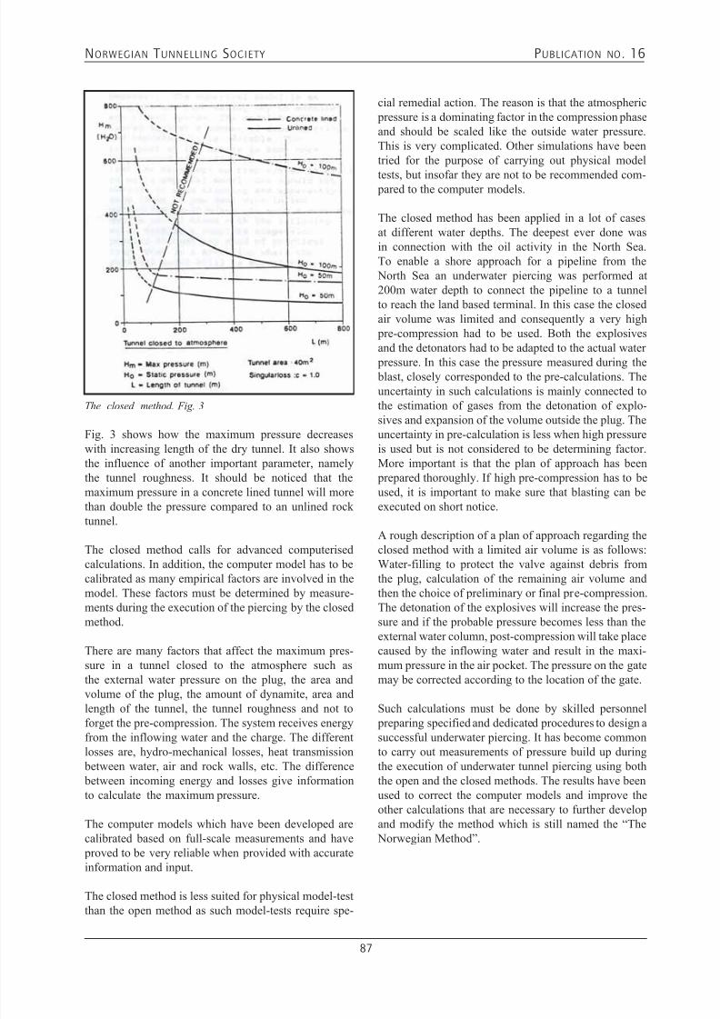
7/21/2019 Publication 16
http://slidepdf.com/reader/full/publication-16 89/181
NORWEGIAN T UNNELLING SOCIETY PUBLICATION NO . 16
87
Fig. 3 shows how the maximum pressure decreaseswith increasing length of the dry tunnel. It also showsthe influence of another important parameter, namelythe tunnel roughness. It should be noticed that themaximum pressure in a concrete lined tunnel will morethan double the pressure compared to an unlined rocktunnel.
The closed method calls for advanced computerisedcalculations. In addition, the computer model has to becalibrated as many empirical factors are involved in themodel. These factors must be determined by measure-ments during the execution of the piercing by the closedmethod.
There are many factors that affect the maximum pres-sure in a tunnel closed to the atmosphere such asthe external water pressure on the plug, the area andvolume of the plug, the amount of dynamite, area and
length of the tunnel, the tunnel roughness and not toforget the pre-compression. The system receives energyfrom the inflowing water and the charge. The differentlosses are, hydro-mechanical losses, heat transmission between water, air and rock walls, etc. The difference between incoming energy and losses give informationto calculate the maximum pressure.
The computer models which have been developed arecalibrated based on full-scale measurements and have proved to be very reliable when provided with accurateinformation and input.
The closed method is less suited for physical model-testthan the open method as such model-tests require spe-
The closed method. Fig. 3
cial remedial action. The reason is that the atmospheric pressure is a dominating factor in the compression phaseand should be scaled like the outside water pressure.This is very complicated. Other simulations have beentried for the purpose of carrying out physical model
tests, but insofar they are not to be recommended com- pared to the computer models.
The closed method has been applied in a lot of casesat different water depths. The deepest ever done wasin connection with the oil activity in the North Sea.To enable a shore approach for a pipeline from the North Sea an underwater piercing was performed at200m water depth to connect the pipeline to a tunnelto reach the land based terminal. In this case the closedair volume was limited and consequently a very high pre-compression had to be used. Both the explosivesand the detonators had to be adapted to the actual water pressure. In this case the pressure measured during the blast, closely corresponded to the pre-calculations. Theuncertainty in such calculations is mainly connected tothe estimation of gases from the detonation of explo-sives and expansion of the volume outside the plug. Theuncertainty in pre-calculation is less when high pressureis used but is not considered to be determining factor.More important is that the plan of approach has been prepared thoroughly. If high pre-compression has to beused, it is important to make sure that blasting can beexecuted on short notice.
A rough description of a plan of approach regarding theclosed method with a limited air volume is as follows:Water-filling to protect the valve against debris fromthe plug, calculation of the remaining air volume andthen the choice of preliminary or final pre-compression.The detonation of the explosives will increase the pres-sure and if the probable pressure becomes less than theexternal water column, post-compression will take placecaused by the inflowing water and result in the maxi-mum pressure in the air pocket. The pressure on the gatemay be corrected according to the location of the gate.
Such calculations must be done by skilled personnel preparing specified and dedicated procedures to design asuccessful underwater piercing. It has become commonto carry out measurements of pressure build up duringthe execution of underwater tunnel piercing using boththe open and the closed methods. The results have beenused to correct the computer models and improve theother calculations that are necessary to further developand modify the method which is still named the “The Norwegian Method”.
7/21/2019 Publication 16
http://slidepdf.com/reader/full/publication-16 90/181
NORWEGIAN T UNNELLING SOCIETY PUBLICATION NO . 16
88
AF has broad experience
in underground work • Hydropower stations
• Caverns for different usesfrom nuclear disposal to water treatment
• Oil storages
• Road and railwaytunnels
• Own department for shotcreting
For further information
Call +47 22 89 11 00 / www.afgruppen.no
…a reliable partner
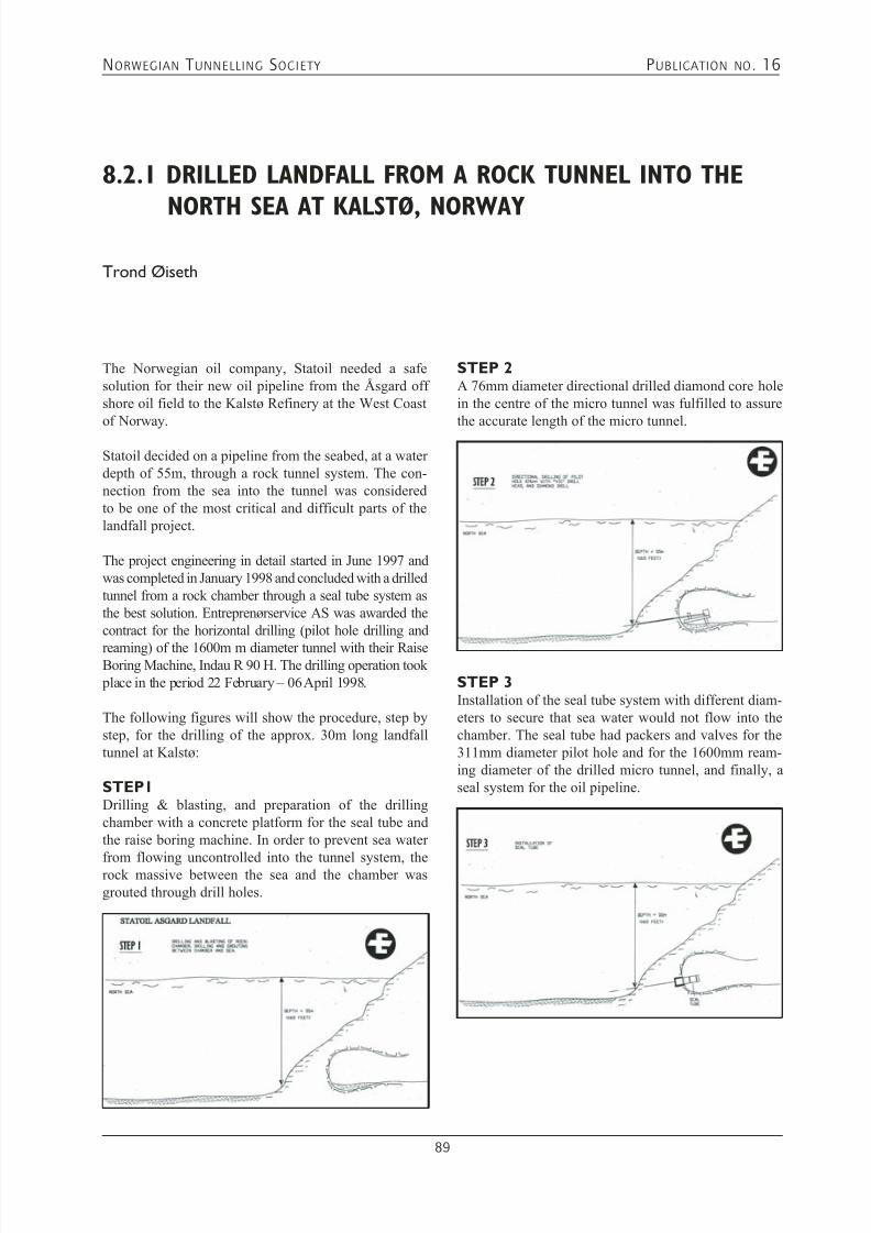
7/21/2019 Publication 16
http://slidepdf.com/reader/full/publication-16 91/181
NORWEGIAN T UNNELLING SOCIETY PUBLICATION NO . 16
89
8.2.1 DRILLED LANDFALL FROM A ROCK TUNNEL INTO THE
NORTH SEA AT KALSTØ, NORWAYTrond Øiseth
The Norwegian oil company, Statoil needed a safesolution for their new oil pipeline from the Åsgard offshore oil field to the Kalstø Refinery at the West Coastof Norway.
Statoil decided on a pipeline from the seabed, at a waterdepth of 55m, through a rock tunnel system. The con-nection from the sea into the tunnel was consideredto be one of the most critical and difficult parts of thelandfall project.
The project engineering in detail started in June 1997 andwas completed in January 1998 and concluded with a drilledtunnel from a rock chamber through a seal tube system asthe best solution. Entreprenørservice AS was awarded thecontract for the horizontal drilling (pilot hole drilling and
reaming) of the 1600m m diameter tunnel with their RaiseBoring Machine, Indau R 90 H. The drilling operation took place in the period 22 February – 06 April 1998.
The following figures will show the procedure, step bystep, for the drilling of the approx. 30m long landfalltunnel at Kalstø:
STEP1Drilling & blasting, and preparation of the drillingchamber with a concrete platform for the seal tube andthe raise boring machine. In order to prevent sea water
from flowing uncontrolled into the tunnel system, therock massive between the sea and the chamber wasgrouted through drill holes.
STEP 2A 76mm diameter directional drilled diamond core holein the centre of the micro tunnel was fulfilled to assurethe accurate length of the micro tunnel.
STEP 3Installation of the seal tube system with different diam-eters to secure that sea water would not flow into thechamber. The seal tube had packers and valves for the311mm diameter pilot hole and for the 1600mm ream-ing diameter of the drilled micro tunnel, and finally, aseal system for the oil pipeline.

7/21/2019 Publication 16
http://slidepdf.com/reader/full/publication-16 92/181
NORWEGIAN T UNNELLING SOCIETY PUBLICATION NO . 16
90
STEP 8The swivel and wire from the winch in the chamber,attached to the pilot drill string were moved to a newdrill string connected to a 1600mm diameter reamerhead. The new drill string was then lowered into the sea
by means of cranes onboard the supply vessel. Then thedrill string was pulled through the 311mm diameter pilothole by use of the winch in the chamber and connectedto the raise boring machine.
STEP 9Reaming of the 1600mm diameter tunnel from seabedto the seal tube. During the boring operation the sup- ply vessel was operating a vacuum system to clean outthe muck from the reaming process. When the ream-ing of the tunnel was completed, the reamer head anddrill string were pushed back to the seabed by the raise
boring machine with some pulling help from a winchonboard the supply vessel. All of the equipment on sea- bed was loaded onboard “Seaway Commander” by useof its own deck cranes.
STEP 4The raise boring equipment and a winch system wereinstalled.
STEP 5Reaming of the 76mm diameter diamond core drill holeto 12 ¼ inch (311mm) diameter by use of a roller reamerwith a guide tip from the chamber, through the seal tubeand out to the seabed.
STEP 6 AND 7Connection of swivel and wire from the winch to theinner end of the drill string in the chamber. The 37mlong, 10 inch diameter drill string was then pulled out ofthe pilot hole by means of a winch onboard the vessel,“Seaway Commander” and a block wheel mounted on a10 ton counter weight in the bottom of the fjord. Thenclamps were fastened to the drill string and the drill
string with pilot bit/roller reamer was then lifted up and placed on the deck of the vessel.
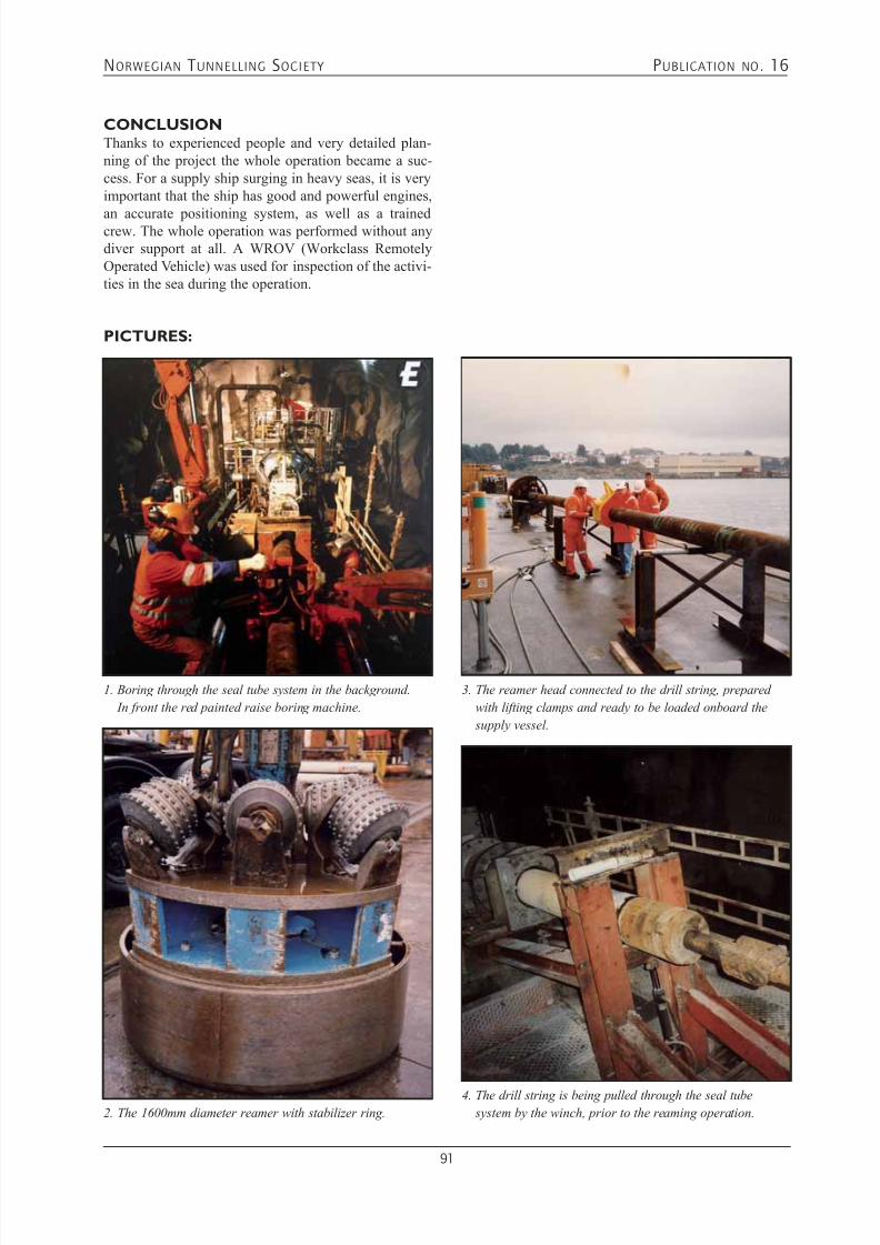
7/21/2019 Publication 16
http://slidepdf.com/reader/full/publication-16 93/181
NORWEGIAN T UNNELLING SOCIETY PUBLICATION NO . 16
91
CONCLUSIONThanks to experienced people and very detailed plan-ning of the project the whole operation became a suc-cess. For a supply ship surging in heavy seas, it is veryimportant that the ship has good and powerful engines,
an accurate positioning system, as well as a trainedcrew. The whole operation was performed without anydiver support at all. A WROV (Workclass RemotelyOperated Vehicle) was used for inspection of the activi-ties in the sea during the operation.
PICTURES:
1. Boring through the seal tube system in the background.
In front the red painted raise boring machine.
2. The 1600mm diameter reamer with stabilizer ring.
3. The reamer head connected to the drill string, prepared
with lifting clamps and ready to be loaded onboard the
supply vessel.
4. The drill string is being pulled through the seal tube
system by the winch, prior to the reaming operation.
7/21/2019 Publication 16
http://slidepdf.com/reader/full/publication-16 94/181
NORWEGIAN T UNNELLING SOCIETY PUBLICATION NO . 16
92
Injection Equipment
Codan AS
Strømsveien 314,1081 Oslo, Norwaywww.codan-gummi.noE-mail:[email protected]: +47 22 90 65 50

7/21/2019 Publication 16
http://slidepdf.com/reader/full/publication-16 95/181
NORWEGIAN T UNNELLING SOCIETY PUBLICATION NO . 16
93
8.2.2 KVITEBJØRN RICH GAS PIPELINE PROJECT
- KOLLSNES LANDFALL - UNDERWATER TUNNEL PIERCING
Arild Neby
Thomas K. Mathiesen
ABSTRACT: Pipelines from offshore oil and gas fields in the NorthSea are serving several onshore process plants on the
Norwegian west coast. The shore approach itself is normally a challenge as the sub-sea topography off the coast is rugged and seldom facilitates landfall siteswith gently sloping sandy beaches coming up from the
continental shelf and slope. Large diameter bore holes drilled from within the process plant area through the rocky barrier and out in the sea have been a common solution for landing pipelines where other methods have not been available. The bored solutions have however often proved to be expensive.
For the Kvitebjørn Rich Gas Pipeline the conceptual solu- tion was a bored landfall with an optional tunnel solution
alternative. During the detail design phase a feasibility study on a tunnelled solution combined with underwater tunnel piercing techniques, adapted from the hydropower civil works sector, revealed that for this project the tunnel solution was feasible. A successful underwater piercing blast connected the Kvitebjørn Landfall tunnel to the sea 12 September 2002.
INTRODUCTIONThe Kvitebjørn gas and condensate field lies in block34/11, east of Gullfaks in the Norwegian North Sea,operated by Statoil. Production from Kvitebjørn began
in 2004. Rich gas and condensate (light oil) fromKvitebjørn are piped to Kollsnes near Bergen andMongstad further north respectively.
Rich gas from Kvitebjørn is piped in the 147 km longOD 30’’ (Ø762 mm) Kvitebjørn Rich Gas Pipeline(KGR) to the process plant at Kollsnes (see Figure 1).After processing at Kollsnes, the dry gas is piped tocontinental Europe. The separated NGL is transported by pipeline to the Vestprosess plant at Mongstad forfractionation into propane, butanes and naphtha.
Condensate travels through the Kvitebjørn Oil Pipeline
(KOR), which ties into the Troll Oil Pipeline II toMongstad (see Figure 1). Based on current plans it is
expected to recover roughly 55 billion cubic metres ofgas and 22 million cubic metres of condensate.
The partners in the license are: Statoil ASA (43.55%),Petoro AS (30%), Norsk Hydro Produksjon a.s (15%), TotalE&P Norge AS (5%) and Enterprise Oil Norge AS (6.45%)
The article covers the detail design and execution of theunderwater piercing for the landfall tunnel as well aswell as going briefly into the pipeline pull-in operationthrough the tunnel to the Kollsnes process plant.
The Kvitebjørn Landfall tunnel was constructed duringthe period May - September 2002. The final piercing atdepth -66 m was executed 12 September 2002. The civilworks part of the whole shore approach project was cost
estimated to approximately NOK 25 million.
The pipeline was pulled in through the landfall tunnel toKollsnes on 15 May 2003. Production from Kvitebjørn began on 26 September 2004. The field began deliver-ing natural gas through the pipeline on 1 October 2004.
Figure 1: Map showing Kvitebjørn Pipelines
(Illustration: Statoil)
DETAIL DESIGN PHASEDesign BasisThe basis for the solution of a landfall tunnel with a final
underwater piercing blast to open the tunnel to the seawas as listed below:
Gas Pipeline (KGR)
Oil Pipeline (KOR

7/21/2019 Publication 16
http://slidepdf.com/reader/full/publication-16 96/181
NORWEGIAN T UNNELLING SOCIETY PUBLICATION NO . 16
94
• Tunnel data: Length approximately 400 m. Slope 1:6. Water filled during pull-in.• Pipeline data:
ID : 710 mm, wall thickness: 28,7 mm
Coating : 6 mm asphalt enamel and 50 mmconcrete weight coating OD incl. coating : 880 mm• Level of piercing point should be between 2.5 and 4.5
m above sea bottom which was situated at approxi-mately -68 m depth.
• Rock surface interpretation at piercing point were to be based on sea bed mapping and ROV view survey(videos), until verification data from exploratory drill-ing become available during construction.
• Offshore dredging work after piercing execution and before pipeline pull-in should be avoided. This crite-rion was probably not to be fulfilled for the conven-tional piercing method, but the design of the final blastshould emphasize on controlling the debris inflow, inorder to avoid or minimise such work.
• The breakthrough piercing blast was to be performedwith a partially water-filled tunnel, ensuring that mostof the blasted rock was flushed into the spoil trap. If anycomplementary work, such as levelling or smoothen-ing, was needed, this was assumed performed by anROV, by seabed based excavator or by dredging froma ship. Dredging carried out from a ship, was believedto probably be the fastest and easiest method.
• The pipeline should be protected by a suitable method
during the pull-in to avoid damage to the coating andthe anodes. It was suggested that the pipeline should be pulled in on a concrete slab on the tunnel invert,
Geological Conditions of the last 30 m of tunnelThe predicted geological conditions and the topographyfor the underwater piercing area was based on interpola-
tion of surface mapping on the island “Storholmen”, oninformation gathered from a core hole drilled parallel tothe landfall tunnel some 40 m away and refraction seis-mic survey, carried out in 1990 for the sub-sea pipelinetunnels forming a part of the landfall for Troll Phase I
Project.
Two seismic sections cover the area along the plannedsub-sea tunnel from Storholmen to the seabed piercing point. The first section, which is following approxi-mately the planned route of the tunnel, indicated a zonewith low to medium seismic velocity located 100 - 110m from Storholmen (11) as well as one major weak-ness zone creating the escarpment holding the piercing point. The second section, which is perpendicular tothe planned tunnel route, is intersecting the first section160 m from Storholmen. This section indicated a 10 mwide weakness zone located about 30 m to the north ofand in parallel to the tunnel alignment. Apart from thesezones the sections only yielded velocities that were high(5700 - 6000 m/s). Neither of the sections indicated anyloose material above the rock seabed.
The rocks within the piercing point area were predictedto consist mainly of granitic gneisses with some minorlayers of dark amphibolitic gneiss, as for the rest of thetunnel. These layers of amphibolites often display de-lamination and are sometimes accompanied by higher joint density and/or clay-filled joints. Pegmatite lenseshad been observed from the core samples and at the
island, and could be expected to occur also in the under-water piercing point area.
Joints along the foliation form the main joint set 1. Thefoliation of the gneiss strikes generally NE-SW with agentle dip (0° - 15°) towards SE. The joint spacing wasobserved to be mainly between 0.2 and 2 metres. The
Figure 2: Engineering geological map showing the piercing point, pipeline route and location of core drilled hole.
(Illustration: Norconsult)

7/21/2019 Publication 16
http://slidepdf.com/reader/full/publication-16 97/181
NORWEGIAN T UNNELLING SOCIETY PUBLICATION NO . 16
95
two other joint sets are steep-dipping and occur approxi-mately normal to joint set 1.
In general, the joints divide the rocks into blocks, whichvary between 0.1 m³ and 3 m³. Most joints have rough
joint surface with slightly undulating joint planes. Insome zones the spacing between the joints is so short thatthe zone may have the character of a crushed zone. Theidentified weakness zones shown on Figure 2 generallyfollow the direction of the two steep-dipping joint sets.
Generally the geological conditions were found to berelatively good, and hence, favourable for a sub-seatunnel. Uncertainty regarding permeability of the rockmass, especially in the piercing area, was to be givenspecial attention during construction phase. Thoroughand continuous routines for exploratory drilling andgrouting, throughout the entire excavation period of thelandfall tunnel as well as at the piercing itself, were a prerequisite.
UNDERWATER TUNNEL PIERCING- PRELIMINARY DESIGNPrincipal methodFor the final piercing of the remaining rock plug, a final blast round using the same principle as for submergedwater intakes, often referred to as “Lake Taps”, was con-sidered the most feasible solution for this project. Thisinvolved preparing the final breakthrough blast from theface of the tunnel, allowing the blasted rock material to
settle in a pre-prepared spoil trap inside the tunnel. AnROV could then be used to fetch a wire located insidethe tunnel to connect this to the pipeline coming fromthe lay barge.
The method comprised that normal excavation proce-dures were followed up to a point 30 m to 100 m fromthe final rock plug location, depending on the local rockmass conditions. From this point on special excavation
procedures would commence, involving careful blast-ing with divided cross sections and extensive use ofexploratory drilling and grouting as part of the excava-tion cycle up to the final rock plug.
Requirements for the tunnel piercingSpace requirementsThe pipeline is approximately 900 mm in diameter.However, the minimum cross section at the pierc-ing point was thought to be determined by the spacerequirements for the ROV needed to pick up and con-nect the pull-in system wire to the pipe. Considerationswere also made to the possibility of facilitating a secondfuture pipeline in the cross section of the final plug, aswell as the blast geometry was governed by the con-sideration and the space needed to facilitate removal ofdebris.
Geometrical requirementsThe pipeline axis through the piercing point shouldhave the same incline of 1:6 as for the rest of the tunnel.Hence, the minimum vertical opening of the piercingshould correspond to this. Two alternative solutionswere proposed for the final plug:• Alternative 1, which aims to remove a large part of the
overhanging roof section at the piercing point.• Alernative. 2, which is a horizontal piercing forming
a tunnel.
For both solutions the rock mass from the final blast was
intended to settle just outside the opening, and in thespoil trap inside the tunnel.
None of the solutions could guaranty that no debriswould settle in the opening. The choice between alterna-tives was to be done based on a cost/benefit evaluation,considering risk for remaining debris and the proceduresto remove such material from the path of the pipeline.The rock mass in an underwater piercing blast would
Figure 3: Preliminary design - plan view of underwater piercing blast round, piercing chamber and spoil trap.
(Illustration: Norconsult)
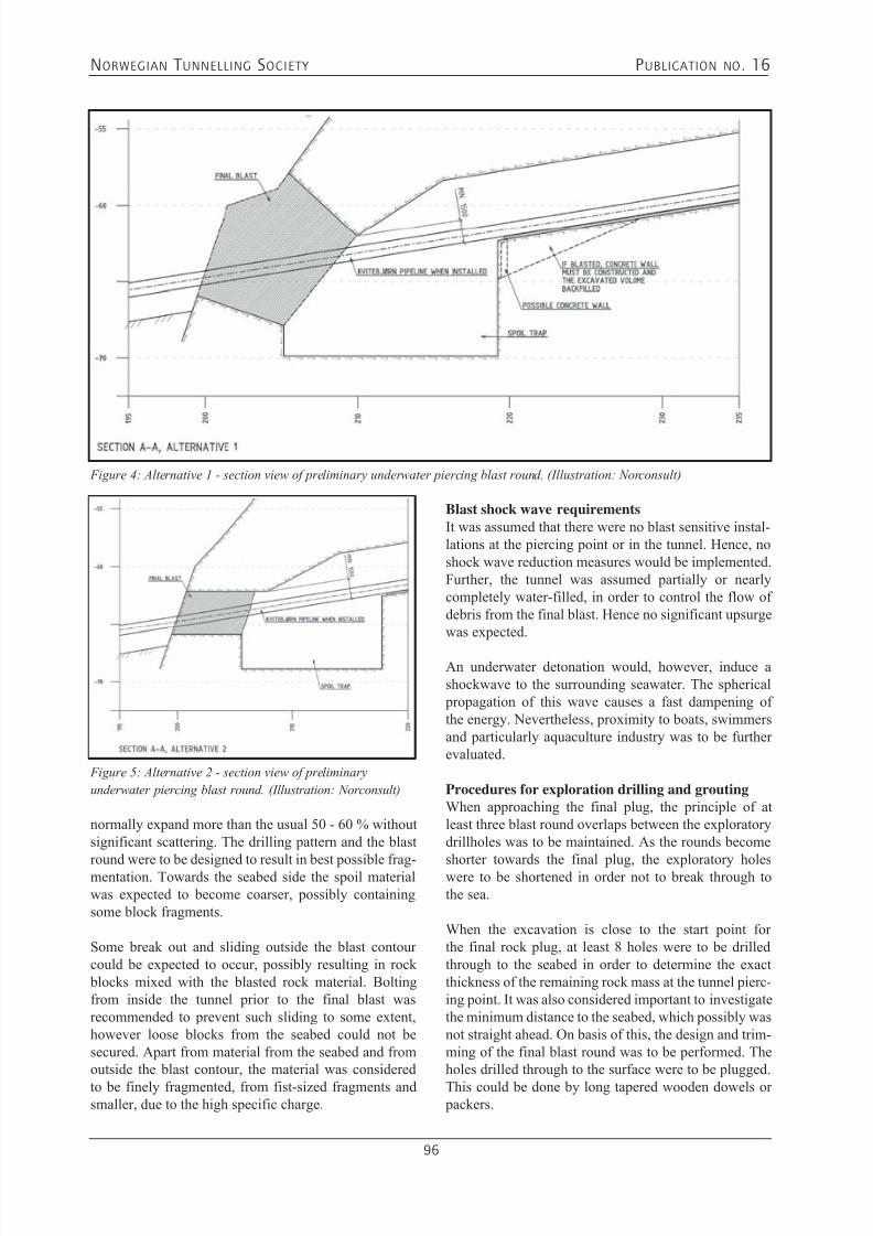
7/21/2019 Publication 16
http://slidepdf.com/reader/full/publication-16 98/181
NORWEGIAN T UNNELLING SOCIETY PUBLICATION NO . 16
96
Figure 5: Alternative 2 - section view of preliminary
underwater piercing blast round. (Illustration: Norconsult)
normally expand more than the usual 50 - 60 % withoutsignificant scattering. The drilling pattern and the blast
round were to be designed to result in best possible frag-mentation. Towards the seabed side the spoil materialwas expected to become coarser, possibly containingsome block fragments.
Some break out and sliding outside the blast contourcould be expected to occur, possibly resulting in rock blocks mixed with the blasted rock material. Boltingfrom inside the tunnel prior to the final blast wasrecommended to prevent such sliding to some extent,however loose blocks from the seabed could not besecured. Apart from material from the seabed and fromoutside the blast contour, the material was considered
to be finely fragmented, from fist-sized fragments andsmaller, due to the high specific charge.
Blast shock wave requirementsIt was assumed that there were no blast sensitive instal-lations at the piercing point or in the tunnel. Hence, noshock wave reduction measures would be implemented.Further, the tunnel was assumed partially or nearlycompletely water-filled, in order to control the flow ofdebris from the final blast. Hence no significant upsurgewas expected.
An underwater detonation would, however, induce ashockwave to the surrounding seawater. The spherical propagation of this wave causes a fast dampening ofthe energy. Nevertheless, proximity to boats, swimmersand particularly aquaculture industry was to be furtherevaluated.
Procedures for exploration drilling and groutingWhen approaching the final plug, the principle of atleast three blast round overlaps between the exploratorydrillholes was to be maintained. As the rounds become
shorter towards the final plug, the exploratory holeswere to be shortened in order not to break through tothe sea.
When the excavation is close to the start point forthe final rock plug, at least 8 holes were to be drilledthrough to the seabed in order to determine the exactthickness of the remaining rock mass at the tunnel pierc-ing point. It was also considered important to investigatethe minimum distance to the seabed, which possibly wasnot straight ahead. On basis of this, the design and trim-ming of the final blast round was to be performed. Theholes drilled through to the surface were to be plugged.
This could be done by long tapered wooden dowels or packers.
Figure 4: Alternative 1 - section view of preliminary underwater piercing blast round. (Illustration: Norconsult)
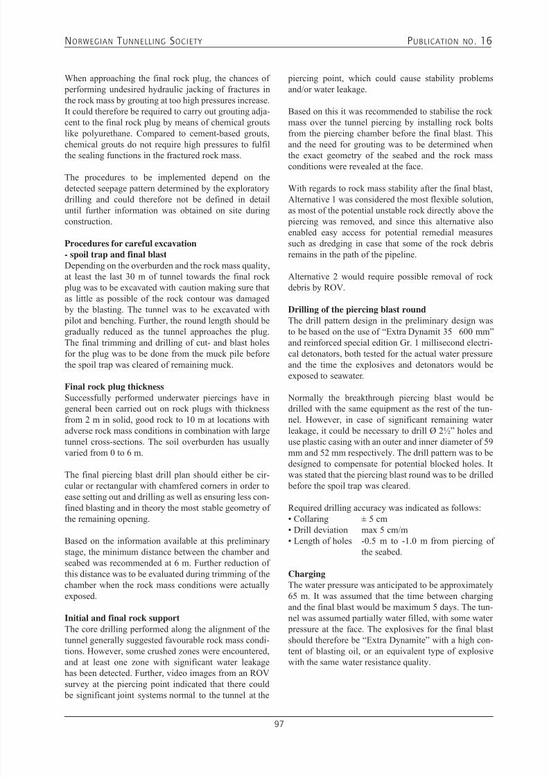
7/21/2019 Publication 16
http://slidepdf.com/reader/full/publication-16 99/181
NORWEGIAN T UNNELLING SOCIETY PUBLICATION NO . 16
97
When approaching the final rock plug, the chances of performing undesired hydraulic jacking of fractures inthe rock mass by grouting at too high pressures increase.It could therefore be required to carry out grouting adja-cent to the final rock plug by means of chemical grouts
like polyurethane. Compared to cement-based grouts,chemical grouts do not require high pressures to fulfilthe sealing functions in the fractured rock mass.
The procedures to be implemented depend on thedetected seepage pattern determined by the exploratorydrilling and could therefore not be defined in detailuntil further information was obtained on site duringconstruction.
Procedures for careful excavation- spoil trap and final blastDepending on the overburden and the rock mass quality,at least the last 30 m of tunnel towards the final rock plug was to be excavated with caution making sure thatas little as possible of the rock contour was damaged by the blasting. The tunnel was to be excavated with pilot and benching. Further, the round length should begradually reduced as the tunnel approaches the plug.The final trimming and drilling of cut- and blast holesfor the plug was to be done from the muck pile beforethe spoil trap was cleared of remaining muck.
Final rock plug thicknessSuccessfully performed underwater piercings have in
general been carried out on rock plugs with thicknessfrom 2 m in solid, good rock to 10 m at locations withadverse rock mass conditions in combination with largetunnel cross-sections. The soil overburden has usuallyvaried from 0 to 6 m.
The final piercing blast drill plan should either be cir-cular or rectangular with chamfered corners in order toease setting out and drilling as well as ensuring less con-fined blasting and in theory the most stable geometry ofthe remaining opening.
Based on the information available at this preliminarystage, the minimum distance between the chamber andseabed was recommended at 6 m. Further reduction ofthis distance was to be evaluated during trimming of thechamber when the rock mass conditions were actuallyexposed.
Initial and final rock supportThe core drilling performed along the alignment of thetunnel generally suggested favourable rock mass condi-tions. However, some crushed zones were encountered,and at least one zone with significant water leakagehas been detected. Further, video images from an ROV
survey at the piercing point indicated that there could be significant joint systems normal to the tunnel at the
piercing point, which could cause stability problemsand/or water leakage.
Based on this it was recommended to stabilise the rockmass over the tunnel piercing by installing rock bolts
from the piercing chamber before the final blast. Thisand the need for grouting was to be determined whenthe exact geometry of the seabed and the rock massconditions were revealed at the face.
With regards to rock mass stability after the final blast,Alternative 1 was considered the most flexible solution,as most of the potential unstable rock directly above the piercing was removed, and since this alternative alsoenabled easy access for potential remedial measuressuch as dredging in case that some of the rock debrisremains in the path of the pipeline.
Alternative 2 would require possible removal of rockdebris by ROV.
Drilling of the piercing blast roundThe drill pattern design in the preliminary design wasto be based on the use of “Extra Dynamit 35 600 mm”and reinforced special edition Gr. 1 millisecond electri-cal detonators, both tested for the actual water pressureand the time the explosives and detonators would beexposed to seawater.
Normally the breakthrough piercing blast would be
drilled with the same equipment as the rest of the tun-nel. However, in case of significant remaining waterleakage, it could be necessary to drill Ø 2½” holes anduse plastic casing with an outer and inner diameter of 59mm and 52 mm respectively. The drill pattern was to bedesigned to compensate for potential blocked holes. Itwas stated that the piercing blast round was to be drilled before the spoil trap was cleared.
Required drilling accuracy was indicated as follows:• Collaring ± 5 cm• Drill deviation max 5 cm/m
• Length of holes -0.5 m to -1.0 m from piercing ofthe seabed.
ChargingThe water pressure was anticipated to be approximately65 m. It was assumed that the time between chargingand the final blast would be maximum 5 days. The tun-nel was assumed partially water filled, with some water pressure at the face. The explosives for the final blastshould therefore be “Extra Dynamite” with a high con-tent of blasting oil, or an equivalent type of explosivewith the same water resistance quality.
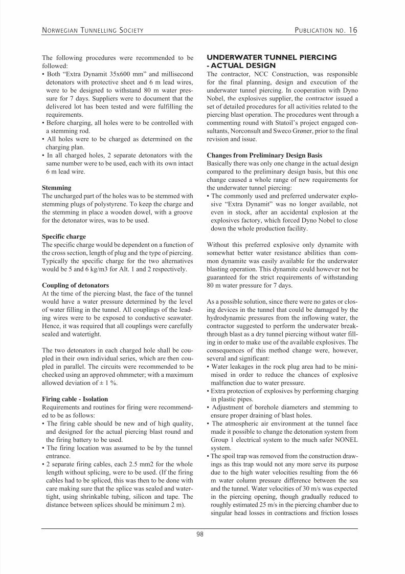
7/21/2019 Publication 16
http://slidepdf.com/reader/full/publication-16 100/181
NORWEGIAN T UNNELLING SOCIETY PUBLICATION NO . 16
98
The following procedures were recommended to befollowed:• Both “Extra Dynamit 35x600 mm” and millisecond
detonators with protective sheet and 6 m lead wires,were to be designed to withstand 80 m water pres-
sure for 7 days. Suppliers were to document that thedelivered lot has been tested and were fulfilling therequirements.
• Before charging, all holes were to be controlled witha stemming rod.
• All holes were to be charged as determined on thecharging plan.
• In all charged holes, 2 separate detonators with thesame number were to be used, each with its own intact6 m lead wire.
StemmingThe uncharged part of the holes was to be stemmed withstemming plugs of polystyrene. To keep the charge andthe stemming in place a wooden dowel, with a groovefor the detonator wires, was to be used.
Specific chargeThe specific charge would be dependent on a function ofthe cross section, length of plug and the type of piercing.Typically the specific charge for the two alternativeswould be 5 and 6 kg/m3 for Alt. 1 and 2 respectively.
Coupling of detonatorsAt the time of the piercing blast, the face of the tunnel
would have a water pressure determined by the levelof water filling in the tunnel. All couplings of the lead-ing wires were to be exposed to conductive seawater.Hence, it was required that all couplings were carefullysealed and watertight.
The two detonators in each charged hole shall be cou- pled in their own individual series, which are then cou- pled in parallel. The circuits were recommended to bechecked using an approved ohmmeter; with a maximumallowed deviation of ± 1 %.
Firing cable - IsolationRequirements and routines for firing were recommend-ed to be as follows:• The firing cable should be new and of high quality,
and designed for the actual piercing blast round andthe firing battery to be used.
• The firing location was assumed to be by the tunnelentrance.
• 2 separate firing cables, each 2.5 mm2 for the wholelength without splicing, were to be used. (If the firingcables had to be spliced, this was then to be done withcare making sure that the splice was sealed and water-tight, using shrinkable tubing, silicon and tape. The
distance between splices should be minimum 2 m).
UNDERWATER TUNNEL PIERCING- ACTUAL DESIGNThe contractor, NCC Construction, was responsiblefor the final planning, design and execution of theunderwater tunnel piercing. In cooperation with Dyno
Nobel, the explosives supplier, the contractor issued aset of detailed procedures for all activities related to the piercing blast operation. The procedures went through acommenting round with Statoil’s project engaged con-sultants, Norconsult and Sweco Grøner, prior to the finalrevision and issue.
Changes from Preliminary Design BasisBasically there was only one change in the actual designcompared to the preliminary design basis, but this onechange caused a whole range of new requirements forthe underwater tunnel piercing:• The commonly used and preferred underwater explo-
sive “Extra Dynamit” was no longer available, noteven in stock, after an accidental explosion at theexplosives factory, which forced Dyno Nobel to closedown the whole production facility.
Without this preferred explosive only dynamite withsomewhat better water resistance abilities than com-mon dynamite was easily available for the underwater blasting operation. This dynamite could however not beguaranteed for the strict requirements of withstanding80 m water pressure for 7 days.
As a possible solution, since there were no gates or clos-ing devices in the tunnel that could be damaged by thehydrodynamic pressures from the inflowing water, thecontractor suggested to perform the underwater break-through blast as a dry tunnel piercing without water fill-ing in order to make use of the available explosives. Theconsequences of this method change were, however,several and significant:• Water leakages in the rock plug area had to be mini-
mised in order to reduce the chances of explosivemalfunction due to water pressure.
• Extra protection of explosives by performing charging
in plastic pipes.• Adjustment of borehole diameters and stemming toensure proper draining of blast holes.
• The atmospheric air environment at the tunnel facemade it possible to change the detonation system fromGroup 1 electrical system to the much safer NONELsystem.
• The spoil trap was removed from the construction draw-ings as this trap would not any more serve its purposedue to the high water velocities resulting from the 66m water column pressure difference between the seaand the tunnel. Water velocities of 30 m/s was expectedin the piercing opening, though gradually reduced to
roughly estimated 25 m/s in the piercing chamber due tosingular head losses in contractions and friction losses
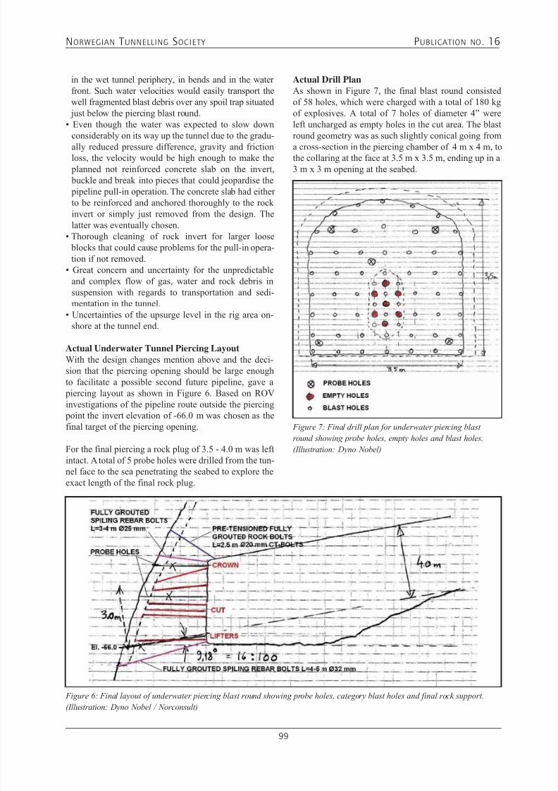
7/21/2019 Publication 16
http://slidepdf.com/reader/full/publication-16 101/181
NORWEGIAN T UNNELLING SOCIETY PUBLICATION NO . 16
99
in the wet tunnel periphery, in bends and in the waterfront. Such water velocities would easily transport thewell fragmented blast debris over any spoil trap situated just below the piercing blast round.
• Even though the water was expected to slow down
considerably on its way up the tunnel due to the gradu-ally reduced pressure difference, gravity and frictionloss, the velocity would be high enough to make the planned not reinforced concrete slab on the invert, buckle and break into pieces that could jeopardise the pipeline pull-in operation. The concrete slab had eitherto be reinforced and anchored thoroughly to the rockinvert or simply just removed from the design. Thelatter was eventually chosen.
• Thorough cleaning of rock invert for larger loose blocks that could cause problems for the pull-in opera-tion if not removed.
• Great concern and uncertainty for the unpredictableand complex flow of gas, water and rock debris insuspension with regards to transportation and sedi-mentation in the tunnel.
• Uncertainties of the upsurge level in the rig area on-shore at the tunnel end.
Actual Underwater Tunnel Piercing LayoutWith the design changes mention above and the deci-sion that the piercing opening should be large enoughto facilitate a possible second future pipeline, gave a piercing layout as shown in Figure 6. Based on ROVinvestigations of the pipeline route outside the piercing
point the invert elevation of -66.0 m was chosen as thefinal target of the piercing opening.
For the final piercing a rock plug of 3.5 - 4.0 m was leftintact. A total of 5 probe holes were drilled from the tun-nel face to the sea penetrating the seabed to explore theexact length of the final rock plug.
Figure 6: Final layout of underwater piercing blast round showing probe holes, category blast holes and final rock support.
(Illustration: Dyno Nobel / Norconsult)
Actual Drill PlanAs shown in Figure 7, the final blast round consistedof 58 holes, which were charged with a total of 180 kgof explosives. A total of 7 holes of diameter 4” wereleft uncharged as empty holes in the cut area. The blast
round geometry was as such slightly conical going froma cross-section in the piercing chamber of 4 m x 4 m, tothe collaring at the face at 3.5 m x 3.5 m, ending up in a3 m x 3 m opening at the seabed.
Figure 7: Final drill plan for underwater piercing blast
round showing probe holes, empty holes and blast holes.
(Illustration: Dyno Nobel)
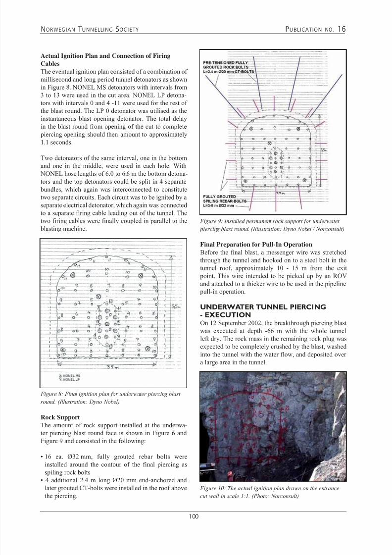
7/21/2019 Publication 16
http://slidepdf.com/reader/full/publication-16 102/181
NORWEGIAN T UNNELLING SOCIETY PUBLICATION NO . 16
100
Actual Ignition Plan and Connection of FiringCablesThe eventual ignition plan consisted of a combination ofmillisecond and long period tunnel detonators as shownin Figure 8. NONEL MS detonators with intervals from
3 to 13 were used in the cut area. NONEL LP detona-tors with intervals 0 and 4 -11 were used for the rest ofthe blast round. The LP 0 detonator was utilised as theinstantaneous blast opening detonator. The total delayin the blast round from opening of the cut to complete piercing opening should then amount to approximately1.1 seconds.
Two detonators of the same interval, one in the bottomand one in the middle, were used in each hole. With NONEL hose lengths of 6.0 to 6.6 m the bottom detona-tors and the top detonators could be split in 4 separate bundles, which again was interconnected to constitutetwo separate circuits. Each circuit was to be ignited by aseparate electrical detonator, which again was connectedto a separate firing cable leading out of the tunnel. Thetwo firing cables were finally coupled in parallel to the blasting machine.
Figure 8: Final ignition plan for underwater piercing blast
round. (Illustration: Dyno Nobel)
Rock SupportThe amount of rock support installed at the underwa-ter piercing blast round face is shown in Figure 6 andFigure 9 and consisted in the following:
• 16 ea. Ø32 mm, fully grouted rebar bolts wereinstalled around the contour of the final piercing asspiling rock bolts
• 4 additional 2.4 m long Ø20 mm end-anchored and
later grouted CT-bolts were installed in the roof abovethe piercing.
Final Preparation for Pull-In OperationBefore the final blast, a messenger wire was stretchedthrough the tunnel and hooked on to a steel bolt in thetunnel roof, approximately 10 - 15 m from the exit point. This wire intended to be picked up by an ROVand attached to a thicker wire to be used in the pipeline
pull-in operation.
UNDERWATER TUNNEL PIERCING- EXECUTIONOn 12 September 2002, the breakthrough piercing blastwas executed at depth -66 m with the whole tunnelleft dry. The rock mass in the remaining rock plug wasexpected to be completely crushed by the blast, washedinto the tunnel with the water flow, and deposited overa large area in the tunnel.
Figure 9: Installed permanent rock support for underwater
piercing blast round. (Illustration: Dyno Nobel / Norconsult)
Figure 10: The actual ignition plan drawn on the entrance
cut wall in scale 1:1. (Photo: Norconsult)
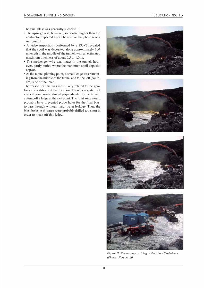
7/21/2019 Publication 16
http://slidepdf.com/reader/full/publication-16 103/181
NORWEGIAN T UNNELLING SOCIETY PUBLICATION NO . 16
101
The final blast was generally successful:• The upsurge was, however, somewhat higher than the
contractor expected as can be seen on the photo seriesin Figure 11.
• A video inspection (performed by a ROV) revealed
that the spoil was deposited along approximately 100m length in the middle of the tunnel, with an estimatedmaximum thickness of about 0.5 to 1.0 m.
• The messenger wire was intact in the tunnel; how-ever, partly buried where the maximum spoil depositsappear.
• At the tunnel piercing point, a small ledge was remain-ing from the middle of the tunnel and to the left (south-ern) side of the inlet.
The reason for this was most likely related to the geo-logical conditions at the location. There is a system ofvertical joint zones almost perpendicular to the tunnel,cutting off a ledge at the exit point. The joint zone would probably have prevented probe holes for the final blastto pass through without major water leakage. Thus, the blast holes in this area were probably drilled too short inorder to break off this ledge.
Figure 11: The upsurge arriving at the island Storholmen
(Photos: Norconsult)

7/21/2019 Publication 16
http://slidepdf.com/reader/full/publication-16 104/181
NORWEGIAN T UNNELLING SOCIETY PUBLICATION NO . 16
102
AS-BUILT LAYOUTBased on the contractor’s changed blast design and theROV survey made after the blast, as-built documenta-tion as shown in Figure 12 was prepared.
Figure 12: As-built lay-out of the Kvitebjørn Landfall. (Illustration: Statoil / Norconsult)

7/21/2019 Publication 16
http://slidepdf.com/reader/full/publication-16 105/181
NORWEGIAN T UNNELLING SOCIETY PUBLICATION NO . 16
103
PIPELINE PULL-IN OPERATIONThe Kvitebjørn Rich Gas Pipeline was pulled in throughthe landfall tunnel to Kollsnes on 15 May 2003.
As can be seen at Figure 13 the pull-in was carried out
from a winch fundament constructed on the process plantside of the strait Njupselsundet between StorholmenIsland and the Kollsnes process plant facility.
Figure 13: Principle sketch showing the Kvitebjørn Rich Gas Pipeline pull-in operation (Illustration: Statoil)
The pull-in operation was performed in an efficient waywith continuous pull from lay-barge to shore withoutany modifications made to the pipeline design (concretecoated line pipe).
Figure 14: The lay-barge in position for pipeline pull-in (Photo: Norconsult)

7/21/2019 Publication 16
http://slidepdf.com/reader/full/publication-16 106/181
NORWEGIAN T UNNELLING SOCIETY PUBLICATION NO . 16
104
Figure 15: View from inside the landfall tunnel prior to the pipeline pull-in (Photo: Statoil)
Figure 16: Overview picture from the Kollsnes landing site prior to the pipeline pull-in. Pull-in wire direction illustrated with
dark line. (Photo: Statoil)
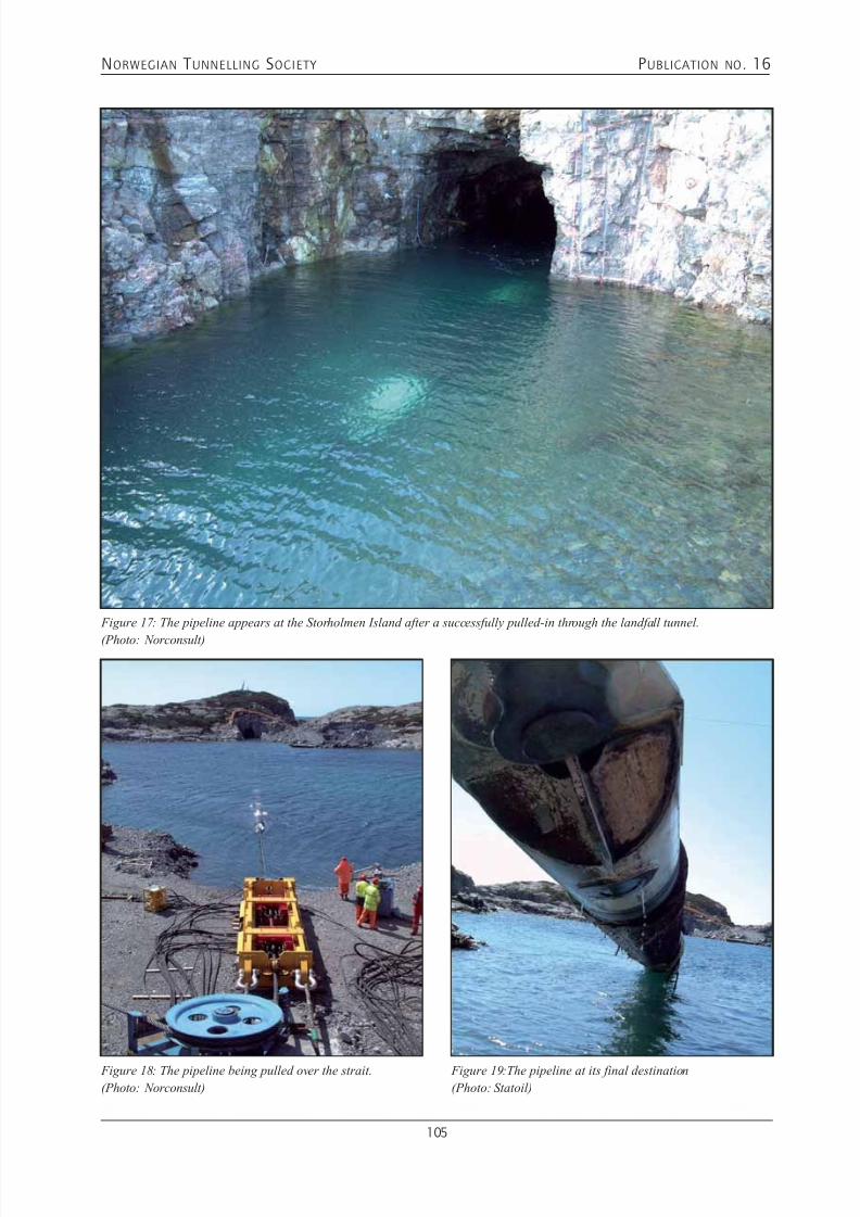
7/21/2019 Publication 16
http://slidepdf.com/reader/full/publication-16 107/181
NORWEGIAN T UNNELLING SOCIETY PUBLICATION NO . 16
105
Figure 17: The pipeline appears at the Storholmen Island after a successfully pulled-in through the landfall tunnel.
(Photo: Norconsult)
Figure 18: The pipeline being pulled over the strait.
(Photo: Norconsult)
Figure 19:The pipeline at its final destination
(Photo: Statoil)
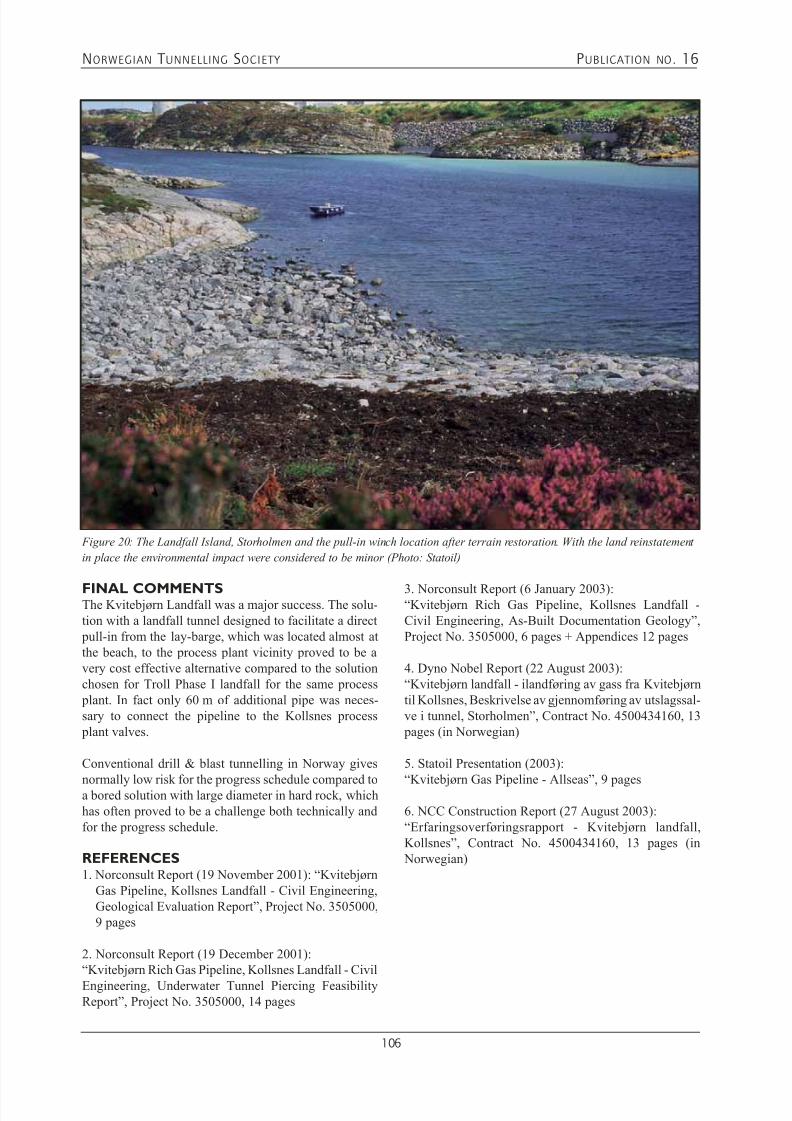
7/21/2019 Publication 16
http://slidepdf.com/reader/full/publication-16 108/181

7/21/2019 Publication 16
http://slidepdf.com/reader/full/publication-16 109/181

7/21/2019 Publication 16
http://slidepdf.com/reader/full/publication-16 110/181
NORWEGIAN T UNNELLING SOCIETY PUBLICATION NO . 16
108
This article summarises briefly the experiences fromthe piercing blasts performed in the Seawater Intakeand Outlet Tunnels at Melkøya 2003-12-03 at 16h00 by
the Site Preparation contractor AFS Pihl Group. Otherobservations like weather and tunnel conditions directlyinfluencing on the blast and inflow performance, isevaluated.
Further the results of the water velocity verification car-ried out during the piercing are presented. The resultsare compared to computer model-based predictions,made prior to the blast.
The tunnels were originally designed to allow for blast-ing with an air cushion towards the separating rock plug
at the sea bottom. The air pockets were to be created byfilling the tunnels with water and entrapping air in theinclined tunnel portions towards the underwater pierc-ing points (Figure 6 and 7).
GENERAL GEOLOGYThe rocks at Melkøya and presumably the area to thenorthwest belong to the Kalak nappe complex contain-ing numerous individual thrust sheets. At Melkøya therock mass consists of gneiss and the foliation strikesENE dipping gently southwards. Mylonite benches and bands rich in biotite or amphibole occur in the gneisson the island. These features, presumably thrust sheet
boundaries, often create scarps where competent sub-horizontal benches overlay less competent layers.
Figure 2: Perspective view of the subsea installations, from the gas field to Melkøya. (Illustration: Statoil)
Major trends of discontinuities and prominent faults andweakness zones are shown on Figures 3 and 4.
The landforms on the island reflect the WNW and ENEdiscontinuity directions; joint set 2 and 3, coupled withthe sub-horizontal foliation, joint set 1, on Figure 4.The same trend may be discerned from the bathymetricmaps covering the area of planned piercings to the NWof the island.
Figure 4: Joint rosette. (Illustration Norconsult)

7/21/2019 Publication 16
http://slidepdf.com/reader/full/publication-16 111/181
NORWEGIAN T UNNELLING SOCIETY PUBLICATION NO . 16
109
Figure 3: Observed weakness zones and major joints.
(Illustration Norconsult)
UNDERWATER TUNNEL PIERCING- DESIGN IMPLICATIONSThe cooling water for the process plant is taken from thesea at depth -80 m through an underwater tunnel piercingand an approximately 1075 m long Intake Tunnel. Thecooling water is discharged to the sea at depth - 30 m
through an approximately 365 m long Outlet Tunnel con-nected to the sea by another underwater tunnel piercing.
The contractor, AFS Pihl Group, was responsible for thefinal planning, design and execution of the underwater
tunnel piercing. In cooperation with Norconsult, thecontractor issued a set of detailed procedures, designreviews and method statement reports for all activitiesrelated to the tunnel excavation and the underwater piercing blast operation. The reports and procedureswent through a commenting round with the operator,Statoil, prior to the final revisions and issues.
Design Basis RequirementsBasic requirements were listed as follows:• The tunnels shall provide sufficiently large and stable
openings for the flow of cooling water.• Loose deposits at the piercing locations must be pre-
vented from accumulation in the tunnels in amountsthat could impair the function.
• Flooding of the site located 5 metres above mean sealevel is not acceptable
• The tunnels or material left in the tunnels must not produce erosive agents during operation.
• Roadbed shall be removed to top of rock knobs in theinvert and this shall be the state also after completed piercing.
Figure 5: Plan view of the Intake and Outlet Tunnel. (Illustration: Multiconsult /Statoil)

7/21/2019 Publication 16
http://slidepdf.com/reader/full/publication-16 112/181
NORWEGIAN T UNNELLING SOCIETY PUBLICATION NO . 16
110
Figure 7: Longitudinal section of the Outlet Tunnel with spoil
trap and low point. (Illustration: Multiconsult /Statoil)
EROSIVE AGENTSThe requirement regarding erosive agents together witha construction schedule that was based on the comple-tion of concrete works in the receiver pits prior to theunderwater piercing blasts against set stop logs gateswas the background for the tentative piercing layoutincluding spoil traps. Underwater piercings performedwith pressurised air cushions towards the charged blastrounds would in theory give small water velocities forthe inflowing seawater and most of the rock debris from
the blast was expected to fall down in the spoil trap.
Figure 6: Longitudinal section of the Intake Tunnel with spoil trap and low point. (Illustration: Multiconsult /Statoil)
Hence the debris from the blast itself would hardly con-tribute to additional loose material on the tunnel invertcontaining erosive agents.
The contractor and their consultant went thoroughly intothe presumptions and requirements for the whole under-water tunnel piercing concept during the detail design phase for the final blasting operations.
Regarding erosive agents the rock mass itself could bedisregarded as a source, since the tunnel and the rockmass adjacent to the piercing would be adequately sup- ported. This was leaving the loose materials, which isleft on the invert as a possible source. This materialis susceptible to erosion by the permanent flow in thetunnel and may be transported towards the receiver pits.Figure 8 below shows a diagram for erosion, transportand sedimentation as a function of flow velocity, alsoknown as the “Hjulström diagram”. According to thediagram fine sand is the fraction most susceptible to
erosion.
Figure 8: Hjulström diagram (Illustration: F. Hjulström, modified by J.C. Harms et al. 1982)

7/21/2019 Publication 16
http://slidepdf.com/reader/full/publication-16 113/181
NORWEGIAN T UNNELLING SOCIETY PUBLICATION NO . 16
111
It should be noted that the volume of material, whichmay be eroded, is proportional to the exposed surfaceof spoil at the invert and not to the bulk of spoil left inthe tunnel. The erosion stops as soon as a protective skinof coarser material is created. The formation of a stable
protective skin is a natural process, also observed inhydro-tunnels with water-velocities in the range of up to1.5 m/sec and where roadbeds that are left in place, haveremained intact after years of operation. The designcapacity of seawater flow in the intake tunnel is reportedas 96 000 m3/hour, which corresponds to a maximumvelocity of approximately 1 m/sec in the intake tunnel.
The above discussion indicates that there would be no practical difference regarding erosive potential whetherthe roadbeds were left in place on the invert, the invertwas cleaned to top of rock knobs or the invert to someextent was covered by debris from the blasting of thefinal plug. The alternatives regarding tunnel cleaningwas therefore considered to be either to clean the tunnelcompletely or to do nothing, and hence also considerletting spoil flow into and through the tunnel during piercing.
Underwater Tunnel Piercing AlternativesBased on the conclusion regarding erosive agents, alter-native methods of underwater tunnel piercings wereevaluated together with the tentative method by use ofcomputer model analysis.As the amount of erosive agents was independent of the
method chosen, only the type of explosives to be usedwas dependent on the selected alternative for piercing.All calculations were based on a cross section at the piercing of 9 m2 and that the blasts were performed atmean sea level at elevation 0 (project elevation +95.0m).
The evaluated alternatives for piercing methods arelisted as follows:
1. Dry piercing; dry tunnels:a. Stop log gates closed
b. Stop log gates open
2. Water filled tunnel with air cushion to separatepiercing plug and water:
a. Water filling between the piercing plug and closed thestop log gates
b. Water filling of the tunnels, including receiver pits, but with the gates open
3. Water filled tunnels without any air cushion:a. Water filling between the piercing plug and the closed
stop log gates b. Water filling of the tunnels, including receiver pits,
but with the gates open
All calculations were based on a cross section at the piercing of 9 m2 and that the blasts were performed atmean sea level at elevation 0.
Alternative 1b) with dry tunnel and open gates was
recommended as piercing method for the intake and theoutlet tunnels. This alternative was the simplest solutionfrom a technical point of view. It gave a comfortablesafety against flooding of the site and was also consid-ered the most economic alternative. The potential incon-venience due to risk of erosive agents during operation,was recommended to be further evaluated, but not con-sidered to constitute a risk of significance.
Alternative 1a) with dry piercing and closed gates werenot recommended for further evaluation due to the high pressure generated at the gates. The same was the casefor alternative 3a) with water filled tunnels without acontrolled air cushion at the face and the gates closed.
The remaining alternatives; 2a) water filling to elevationabove -9.0 m, controlled air cushion and gates closed,2b) water filling to elevation above -9.0 m, controlled aircushion and gates open and 3b) water filling to elevationabove sea level, no controlled air cushion and open gates,were all feasible and recommendable solutions. The sim- pler solution among these alternatives seemed, however,to be alternative 2b), without a controlled air cushion andwith the gates open, even if this alternative demanded theuse of more water resistant Ø64 mm primers with a cast
body of TNT/RDX and a cap sensitive part of pressedPETN, as the preferred explosive. This solution requireddrilling of larger blast holes than usual and an increasedvolume of water for filling of the pits.
For detail design of the selected alternative, 2b) dry piercing with stop logs open, more detailed calculationson up-surge, pressure pulse and sediment transport were performed together with detailed procedures for thework towards and at the piercing.
ACTUAL TUNNEL EXCAVATION
Compared to the theoretical layout shown on Figure5-7, the tunnels have actually been excavated as shownon the planar parts of sketches shown in Figure 9 and12 with typical cross-sections as shown in Figure 10and 11.
At approximately every 100 m in the Intake Tunnel,a turning and mucking niche of some 350 - 400 m3have been excavated. For the Outlet Tunnel, similarsized niches have been excavated at two locations. Inaddition, for both tunnels, pumping and cable nichesof some 40 - 50 m3 have been excavated at intervals ofapproximately 100 m on the opposite side of the tunnel
compared to the large T&M niches, numbering 6 in theIntake Tunnel and 2 in the Outlet Tunnel.

7/21/2019 Publication 16
http://slidepdf.com/reader/full/publication-16 114/181
NORWEGIAN T UNNELLING SOCIETY PUBLICATION NO . 16
112
Figure 13: Drilling of underwater piercing blast round for Intake Tunnel completed. (Photo: AFS Pihl)
Figure 9: Intake Tunnel layout with niches (Illustration: Norconsult)
Figure 10: Typical tunnel cross-
section
Figure 11: Piercing shaft cross-
section
Figure 12: Outlet Tunnel layout with niches
(Illustration: Norconsult)

7/21/2019 Publication 16
http://slidepdf.com/reader/full/publication-16 115/181
NORWEGIAN T UNNELLING SOCIETY PUBLICATION NO . 16
113
EXPLORATORY DRILLING AND ROCKMASS GROUTINGA detailed exploratory drilling programme was elabo-rated for the different portions of the cooling watertunnels. The programme was divided into 4 stages fol-
lowing specific chainage numbers related to the actualrock cover.
Figure 14 and 15 shows the planned extent of explora-tory drilling and rock mass grouting for both tunnels.
Figure 16: Intake Tunnel - 3D image of actual executed exploratory drilling from ch. 1063. (Illustration: AFS Pihl)
Figure 14: Intake Tunnel - exploratory drilling programme and rock mass grouting. (Illustration: Norconsult)
Figure 15: Outlet Tunnel - exploratory drilling programme and rock mass grouting. (Illustration: Norconsult)

7/21/2019 Publication 16
http://slidepdf.com/reader/full/publication-16 116/181
NORWEGIAN T UNNELLING SOCIETY PUBLICATION NO . 16
114
ACTUAL DRILLING, CHARGING ANDIGNITIONAlso for the circular piercing blast rounds, there werein the final stages made some adjustments to the initialexcavation plan. Instead of diameter of 3.4 m, the final
round was drilled with a 3.5 m diameter in order ensurethe minimum required opening. The circular cross-sec-tion increased then from 9.1 m2 to 9.6 m2.
All blast holes were drilled with Ø48 mm bits. Largediameter holes were reamed up to 102 mm (4”) diam-eter.
Drill hole data were as follows:Large (uncharged) holes: 5 pcsBlast (charged) holes: 79 pcsCut holes: 16 pcsStoping holes, Ring 1: 14 pcsStoping holes, Ring 2: 21 pcsContour holes: 28 pcs
The final piercing blast rounds were charged with ordi-nary dynamite specially tested for water resistance. Thedynamite cartridges were loaded into thin PVC-pipesclosed in the hole bottom end.
Charge quantities and specific charges were as follows:Blast (charged) holes: 327.3 kg → 8.6 kg/sm3Cut holes: 72.8 kg → 14.6 kg/sm3Stoping holes, Ring 1: 14 pcs
Stoping holes, Ring 2: 21 pcs → 5.9 kg/sm3Contour holes: 28 pcs
Figure 17: Ignition plan for a Ø3.5 m underwater tunnel
piercing blast. (Illustration: AFS)
The ignition system consisted of a double set of detona-tors in each hole. The detonators used were a mix of Nonel MS and Nonel LP, coupled in two separate cir-cuits. Except for the zero-detonator, millisecond (MS)detonators were used in the cut area. In the rest of the
blast round Long Period (LP) detonators were used (seeFigure 17). A double set of shotfiring cables of type Nonel Dynoline were cross-connected to both the igni-tion circuits.
ESTIMATED HEAD LOSS AND WATERVELOCITYThe extra niche volume actually excavated had not beenaccounted for, neither in the calculations of head lossduring operation nor the water velocity model for the piercing performance.
For the operational stage of the plant, the volume of theniches adds positive area to the tunnel cross-section andgives as such a beneficial effect on the head loss. Alsothe niches will serve as sedimentation basins as thewater velocity will be reduced at these locations due tothe considerable increase in the tunnel cross-section.
The increased size of the piercing opening will alsocontribute to reduced water loss during the operationalstage. For the predictions of water inflow and velocityduring and just after the blast, a larger opening will givea marginal reduction in head loss and a somewhat higherwater velocity below the opening.
For the calculations on timing of piercing blasts andwater velocity in the tunnels during the piercing opera-tion, the niches added some uncertainty to the waterfront movement in the dry tunnel, as the niches wouldserve as energy dissipaters as well as causing a pistoneffect on the advancing water column. On the otherhand, the effect of higher intake velocity contributessomewhat in the other direction.
WATER ACCUMULATION AT LOW
POINTS PRIOR TO BLASTINGAfter the pumps were stopped and the discharge systemremoved the water levels at the low point in both tunnelswere measured twice prior to blasting. Based on thesemeasurements the following water leakage rates have been calculated:
Intake Tunnel: 122 l/minOutlet Tunnel: 77 l/min
The above water ingress rates give water accumulation pictures as shown on Figures 18 and 19 at the respectivemoments of blasting for the two tunnels.
These levels of accumulated water gave comfortablesafety margins to the recommended maximum levels.

7/21/2019 Publication 16
http://slidepdf.com/reader/full/publication-16 117/181
NORWEGIAN T UNNELLING SOCIETY PUBLICATION NO . 16
115
TIDE AND WEATHER CONDITIONSThe blasting time at 16h00 had been chosen specifi-cally to coincide with the afternoon low tide in order tomaximize the possible safety margins for the upsurge inthe pits. The tide fluctuations for 3 December 2003 aregiven in Figure 20. Meteorological records are given inFigure 21.
Figure 18: Water accumulation at the intake tunnel low point
at the moment of blasting. (Illustration: Norconsult)
Figure 19: Water accumulation at the outlet tunnel low point
at the moment of blasting. (Illustration: Norconsult)
Figure 20: Tide fluctuations for Hammerfest without influ-
ence of weather 3 December 2003. (Illustration: www.math.
uio.no)
Figure 21: Meteorological data from Hammerfest Airport 3 December 2003. (Illustration: norwegian.wunderground.com)
As can be seen from the data, the low tide is estimatedto -0.64 m below normal zero, which gives a projectelevation of 94.36 m for the sea level, without takinginto consideration the weather conditions present.
The combined effect of the barometric high pressure before noon, the lack of precipitation and the increasingwind from WSW is calculated to have reduced the lowtide level at 16h00 by roughly 20 mm. The predictedupsurge from the calculations, which was 0.6 m for theIntake pit and 0.9 m for Outlet pit, would then become94.34 m + 0.6 m = 94.94 m. As the two pits were not
separated by the initially planned concrete wall, at thetime of piercing, the upsurge of the Intake pit wouldgovern the maximum upsurge capability.

7/21/2019 Publication 16
http://slidepdf.com/reader/full/publication-16 118/181
NORWEGIAN T UNNELLING SOCIETY PUBLICATION NO . 16
116
ADJUSTED TIMING BETWEEN BLASTSThe timing of the two piercing blasts was proposed totake place with a 170 second interval between the IntakeTunnel and the Outlet Tunnel. This interval was basedon a preliminary survey of the excavated pits, which
located the high point in-between the two connected pitsat project elevation +89.0 m (El. -6.0 m), as well as thedesire to have the two waterfronts levelling simultane-ously at this common high point.
After the preliminary cleaning of the pit inverts prior to blasting was completed, it became clear that the actualhigh point between the two pit areas was not located asindicated by the preliminary survey, but was coincidingwith the stop log body sill of the Outlet Tunnel apertureat project elevation +88.47 m (El. -6.53 m).
If maintaining the 170-second delay for the OutletTunnel blast, there was an obvious chance that waterfrom the Intake Tunnel could enter into the OutletTunnel before the waterfront of the Outlet piercing hadreached the pit. This fact together with the larger pierc-ing blast cross-sections and the significant increase involumes contributed by the turning & mucking nichesnecessitated an adjusted timing of the blasting interval.
Based on new calculations the interval was reduced to75 seconds between firing of the Intake piercing blastand the Outlet piercing blast. The predictions were then
that the waterfront of the Intake Tunnel should arrive inthe pit 124 seconds after the detonation of the piercinground in the Intake Tunnel and that the Outlet Tunnelwaterfront should arrive in the pit 5 seconds later than theIntake waterfront. The predicted travel time for the OutletTunnel waterfront would then amount to 55 seconds.
This adjustment also gave the shot firer an additional80 seconds safety margin in case of any malfunction ortrouble occurrence for the blasting machine used for theOutlet piercing.
RESULTS FROM WATER VELOCITYVERIFICATIONAs part of the verification process of successful pierc-ings into the sea, as well as a calibration of the computermodel used for the prediction of water velocities, waterdischarge, upsurge and arrival times, measurements ofreal water arrival times in the tunnels were initiated.
For measurement of real waterfront arrival times, a totalnumber of 22 sensors were distributed along the twotunnel inverts at recorded locations. The distribution forthe Outlet Tunnel is shown in Figure 24. One such sen-sor (shown on Figures 22 and 23 below) consists of anelectronic clock, which is calibrated and synchronizedwith the other sensors and a computer, that will recorda specific moment of time when the floating waterproofsensor housing is exposed to a trigging movement or adislocation caused by the waterfront.
Figure 24: Location of sensors in Outlet Tunnel (sensors with black circles was recovered after the blast)
Figures 22 and 23: Exterior and interior of a floating waterproof sensor
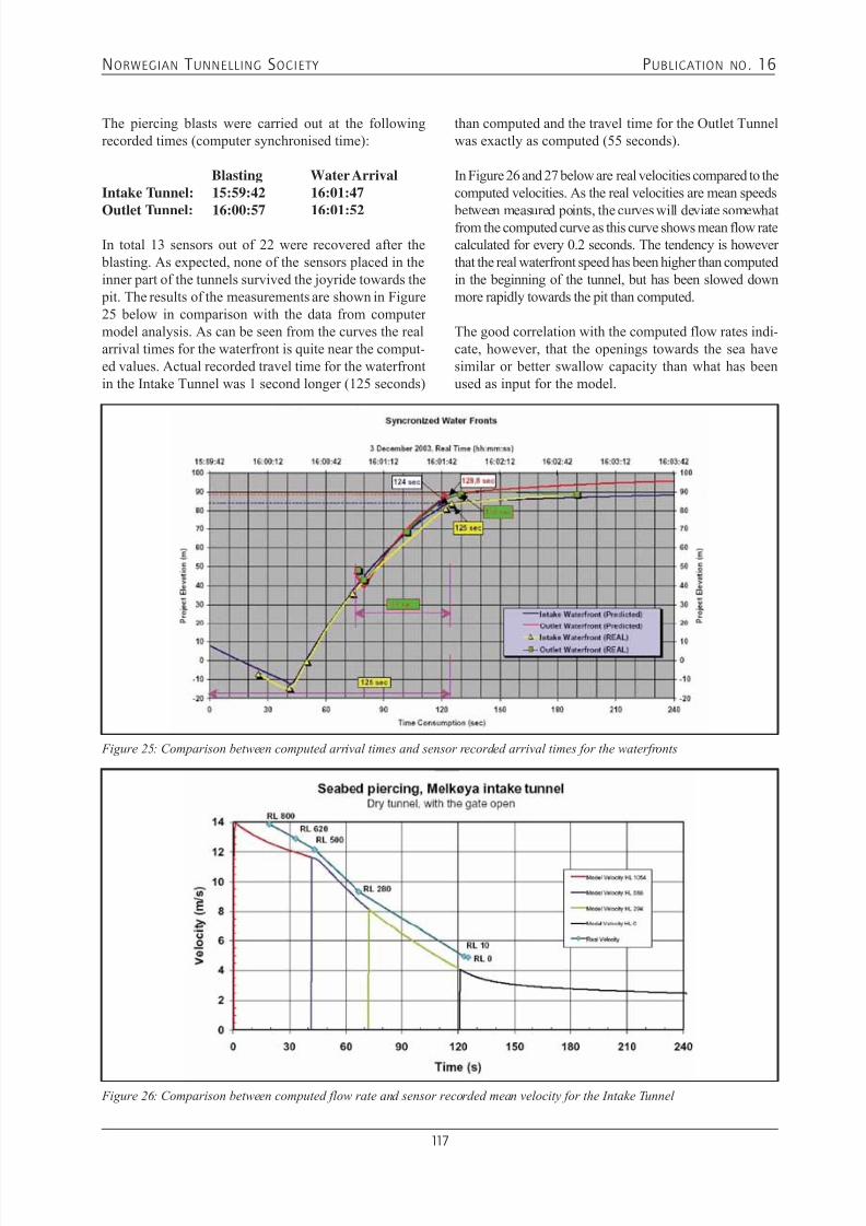
7/21/2019 Publication 16
http://slidepdf.com/reader/full/publication-16 119/181
NORWEGIAN T UNNELLING SOCIETY PUBLICATION NO . 16
117
The piercing blasts were carried out at the followingrecorded times (computer synchronised time):
Blasting Water ArrivalIntake Tunnel: 15:59:42 16:01:47
Outlet Tunnel: 16:00:57 16:01:52
In total 13 sensors out of 22 were recovered after the blasting. As expected, none of the sensors placed in theinner part of the tunnels survived the joyride towards the pit. The results of the measurements are shown in Figure25 below in comparison with the data from computermodel analysis. As can be seen from the curves the realarrival times for the waterfront is quite near the comput-ed values. Actual recorded travel time for the waterfrontin the Intake Tunnel was 1 second longer (125 seconds)
than computed and the travel time for the Outlet Tunnelwas exactly as computed (55 seconds).
In Figure 26 and 27 below are real velocities compared to thecomputed velocities. As the real velocities are mean speeds
between measured points, the curves will deviate somewhatfrom the computed curve as this curve shows mean flow ratecalculated for every 0.2 seconds. The tendency is howeverthat the real waterfront speed has been higher than computedin the beginning of the tunnel, but has been slowed downmore rapidly towards the pit than computed.
The good correlation with the computed flow rates indi-cate, however, that the openings towards the sea havesimilar or better swallow capacity than what has beenused as input for the model.
Figure 25: Comparison between computed arrival times and sensor recorded arrival times for the waterfronts
Figure 26: Comparison between computed flow rate and sensor recorded mean velocity for the Intake Tunnel
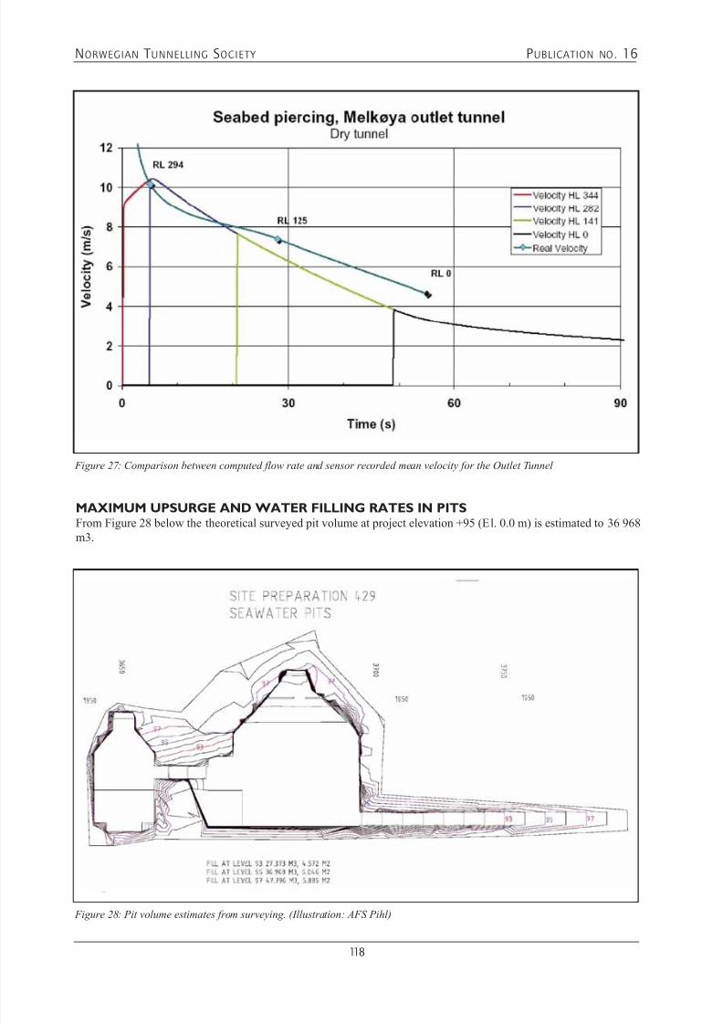
7/21/2019 Publication 16
http://slidepdf.com/reader/full/publication-16 120/181
NORWEGIAN T UNNELLING SOCIETY PUBLICATION NO . 16
118
MAXIMUM UPSURGE AND WATER FILLING RATES IN PITSFrom Figure 28 below the theoretical surveyed pit volume at project elevation +95 (El. 0.0 m) is estimated to 36 968
m3.
Figure 27: Comparison between computed flow rate and sensor recorded mean velocity for the Outlet Tunnel
Figure 28: Pit volume estimates from surveying. (Illustration: AFS Pihl)

7/21/2019 Publication 16
http://slidepdf.com/reader/full/publication-16 121/181
NORWEGIAN T UNNELLING SOCIETY PUBLICATION NO . 16
119
For the full picture of the swallow capacity of the two piercing openings, one will have to look upon the water filling
capacity.
Figure 29: Arial view of receiver pits August 2003. (Photo: Statoil)
Figure 30: Comparison between computed filling times and recorded filling times for the two waterfronts

7/21/2019 Publication 16
http://slidepdf.com/reader/full/publication-16 122/181
NORWEGIAN T UNNELLING SOCIETY PUBLICATION NO . 16
120
Figure 31: Maximum upsurge as wet markings on the stop log structure
From video recordings and time keeping during the pitfilling process, the maximum upsurge was timed to 570seconds (or 9 minutes and 30 seconds) after detona-tion of the Intake Tunnel piercing blast (see Figure 30above). For the Outlet Tunnel this is quite much longerthan what would have been the case if a concrete wallhad separated the pits (red line in Figure 30).
The maximum upsurge was, as indicated on Figures
30 and 31, recorded at project elevation +94.95 m (El.-0.05 m). This is 10 mm higher than the theoretical cal-culations taking weather conditions into consideration.
The mean theoretical swallow capacity for the two tun-nels together was then calculated to be approximately84 m3/sec, which gave a mean capacity of 42 m3/secfor each tunnel. This figure was in line with the averagedischarge rates of the computer model.
CONCLUSIVE COMMENTSThe Seawater Intake and Outlet Tunnels piercings at
Melkøya 3 December 2003 were considered successful.The blasts were carried out in good accordance with allelaborated procedures and plans. The travel times forthe waterfronts and the recorded water filling and maxi-mum upsurge indicate that the openings were sufficient-ly large and that the blasts have detonated as intended.The water-filling rate also indicated that the amount ofdebris from the blasts at the tunnel inverts was evenlydistributed and that the likelihood of any major constric-tions in the tunnel system was minimal. This assumptionwas later confirmed by ROV video images.
REFERENCES1. Norconsult Memo; an1600n (16 June 2003): “Seawater
Intake / Outlet Tunnel at Melkøya, Review of Statuson Geological Information on Seabed Piercings”,Project No. 3757100, 3 pages
2 Norconsult Memo; an1605n (4 July 2003): “SeawaterIntake / Outlet Tunnel at Melkøya, Alternative PiercingMethods”, Project No. 3757100, 6 pages
3 Norconsult Memo; an1607n (29 July 2003): “SeawaterIntake Tunnel at Melkøya, Method Statement forTunnelling of the last 100 m before Piercing Point”,Project No. 3757100, 13 pages
4. Norconsult Memo; an1608n (30 July 2003): “SeawaterOutlet Tunnel at Melkøya, Method Statement forTunnelling of the last 65 m before Piercing Point”,Project No. 3757100, 13 pages
5. Norconsult Memo; an1618n (17 October 2003):
“Seawater Outlet Tunnel at Melkøya, Evaluationof Flow Regime and Method Statement forRectifying Actions in Case of Unsuccessful PiercingPerformance”, Project No. 3757100, 11 pages
6. Norconsult Memo; an1628n (6 February 2003):“Intake / Outlet Tunnels - Melkøya, Summary ofSeawater Tunnel Piercing Blasts”, Project No.3757100, 13 pages
7. Harms, J.C., Southard, J.B., and Walker, R.G. (1982):“Structures and Sequences in Clastic Rocks”: Lecture Notes for Short Course No. 9, Society of Economic
Palaeontologists and Mineralogists, 279 pages.

7/21/2019 Publication 16
http://slidepdf.com/reader/full/publication-16 123/181
NORWEGIAN T UNNELLING SOCIETY PUBLICATION NO . 16
121
8.3.2 CHALLENGING DRILLING AND BLASTING OPERATION IN
STEEP TERRAIN ON SEABED, 82 METRES BELOW SEALEVEL, ORMEN LANGE MAIN CIVIL CONTRACT
Bjørn R. Morseth
ABSTRACTAfter a failed attempt to achieve a tunnel breakthroughon the Ormen Lange project at Nyhamna, in themunicipality of Aukra, Mid-Norway, in October 2005,there was a need to find a safe method of obtaining therequired opening to the sea.
The underwater tunnel piercing site is at a depth of82 metres below sea level. The seafloor at this pointis steep with an inclination of 60 - 70o, and there is a partial overhang.
A project team composed of engineers from bothSkanska and external companies was established. Theteam evaluated several alternative methods, and inJanuary/February 2006, one method emerged as prob-
ably the most suitable, and was investigated further.This method was based on mounting conventional drill-ing equipment on a remote-operated tool carrier. It wasintended that the equipment should rest on the bottom just outside the breakthrough area and be raised andlowered to the bottom from a barge. Development ofthe method involved testing of conventional explosives(Dynoprime/ initiators) that worked at the depths inquestion, modification of drilling equipment, tool car-rier and barge, and customisation and manufacture ofspecial equipment.
As an alternative to this method, another method, whichinvolved plugging the failed tunnel and excavating anew tunnel to breakthrough, was investigated in paral-lel.
After a thorough review of the entire operation, thework on site commenced on 13 March 2006. The drill-ing and blasting operation was completed on Saturday1 April, and a successful breakthrough was established.The need for finishing operations in the opening wasminimal and the operation was considered a success. The total cost of the implemented method was NOK 18
- 20 million.
1. INTRODUCTIONThere are two cooling water tunnels at the Ormen Lange plant. One of the tunnels with a cross-section of 25m2is meant to function as an intake tunnel for coolingwater and pierces the seabed at 82 metres below sealevel. This tunnel is 1,345 metres in length from tunnel portal to piercing point and has a branch to an intake res-ervoir. The other tunnel with a theoretical cross-sectionof 20m2 is an outlet tunnel that is about 980 metres longand pierces the seabed at 40 metres below sea level.One of the purposes of this tunnel to is lead coolingwater from the process plant back out to sea.
The excavation of the tunnels was started in June 2004.The outlet tunnel and intake tunnel were completed andsecured in June 2005, as were the intake and outlet res-
ervoirs with associated shafts.
In the contract with Hydro, Skanska was responsiblefor designing, planning and performing the tunnel breakthroughs to the sea. The approximate position ofthe piercing sites was given by Hydro, but Skanska wasresponsible for their exact positioning.
Figure 1. Plan of cooling water tunnels
Outlet tunnel
Intake tunnel
As can be seen from Figure 1, the outlet tunnel piercesthe seafloor in a relatively flat area. The intake tunnel,
on the other hand, runs along a distinct ridge and endsin a steep rock face. In the light of available bathymet-
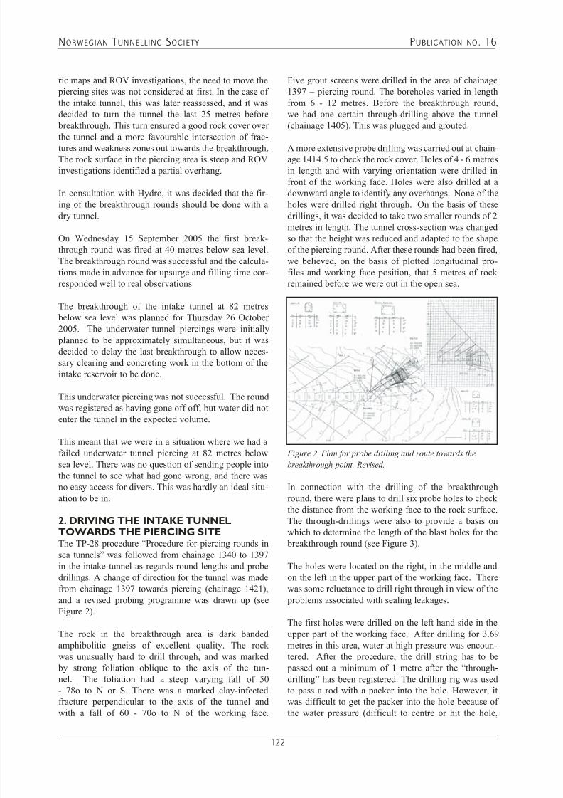
7/21/2019 Publication 16
http://slidepdf.com/reader/full/publication-16 124/181
NORWEGIAN T UNNELLING SOCIETY PUBLICATION NO . 16
122
ric maps and ROV investigations, the need to move the piercing sites was not considered at first. In the case ofthe intake tunnel, this was later reassessed, and it wasdecided to turn the tunnel the last 25 metres before breakthrough. This turn ensured a good rock cover over
the tunnel and a more favourable intersection of frac-tures and weakness zones out towards the breakthrough.The rock surface in the piercing area is steep and ROVinvestigations identified a partial overhang.
In consultation with Hydro, it was decided that the fir-ing of the breakthrough rounds should be done with adry tunnel.
On Wednesday 15 September 2005 the first break-through round was fired at 40 metres below sea level.The breakthrough round was successful and the calcula-tions made in advance for upsurge and filling time cor-responded well to real observations.
The breakthrough of the intake tunnel at 82 metres below sea level was planned for Thursday 26 October2005. The underwater tunnel piercings were initially planned to be approximately simultaneous, but it wasdecided to delay the last breakthrough to allow neces-sary clearing and concreting work in the bottom of theintake reservoir to be done.
This underwater piercing was not successful. The roundwas registered as having gone off off, but water did not
enter the tunnel in the expected volume.
This meant that we were in a situation where we had afailed underwater tunnel piercing at 82 metres belowsea level. There was no question of sending people intothe tunnel to see what had gone wrong, and there wasno easy access for divers. This was hardly an ideal situ-ation to be in.
2. DRIVING THE INTAKE TUNNELTOWARDS THE PIERCING SITEThe TP-28 procedure “Procedure for piercing rounds in
sea tunnels” was followed from chainage 1340 to 1397in the intake tunnel as regards round lengths and probedrillings. A change of direction for the tunnel was madefrom chainage 1397 towards piercing (chainage 1421),and a revised probing programme was drawn up (seeFigure 2).
The rock in the breakthrough area is dark bandedamphibolitic gneiss of excellent quality. The rockwas unusually hard to drill through, and was marked by strong foliation oblique to the axis of the tun-nel. The foliation had a steep varying fall of 50- 78o to N or S. There was a marked clay-infected
fracture perpendicular to the axis of the tunnel andwith a fall of 60 - 70o to N of the working face.
Five grout screens were drilled in the area of chainage1397 – piercing round. The boreholes varied in lengthfrom 6 - 12 metres. Before the breakthrough round,we had one certain through-drilling above the tunnel(chainage 1405). This was plugged and grouted.
A more extensive probe drilling was carried out at chain-age 1414.5 to check the rock cover. Holes of 4 - 6 metresin length and with varying orientation were drilled infront of the working face. Holes were also drilled at adownward angle to identify any overhangs. None of theholes were drilled right through. On the basis of thesedrillings, it was decided to take two smaller rounds of 2metres in length. The tunnel cross-section was changedso that the height was reduced and adapted to the shapeof the piercing round. After these rounds had been fired,we believed, on the basis of plotted longitudinal pro-files and working face position, that 5 metres of rockremained before we were out in the open sea.
Figure 2 Plan for probe drilling and route towards the
breakthrough point. Revised.
In connection with the drilling of the breakthroughround, there were plans to drill six probe holes to checkthe distance from the working face to the rock surface.The through-drillings were also to provide a basis onwhich to determine the length of the blast holes for the breakthrough round (see Figure 3).
The holes were located on the right, in the middle andon the left in the upper part of the working face. Therewas some reluctance to drill right through in view of the problems associated with sealing leakages.
The first holes were drilled on the left hand side in theupper part of the working face. After drilling for 3.69metres in this area, water at high pressure was encoun-tered. After the procedure, the drill string has to be passed out a minimum of 1 metre after the “through-drilling” has been registered. The drilling rig was usedto pass a rod with a packer into the hole. However, it
was difficult to get the packer into the hole because ofthe water pressure (difficult to centre or hit the hole,
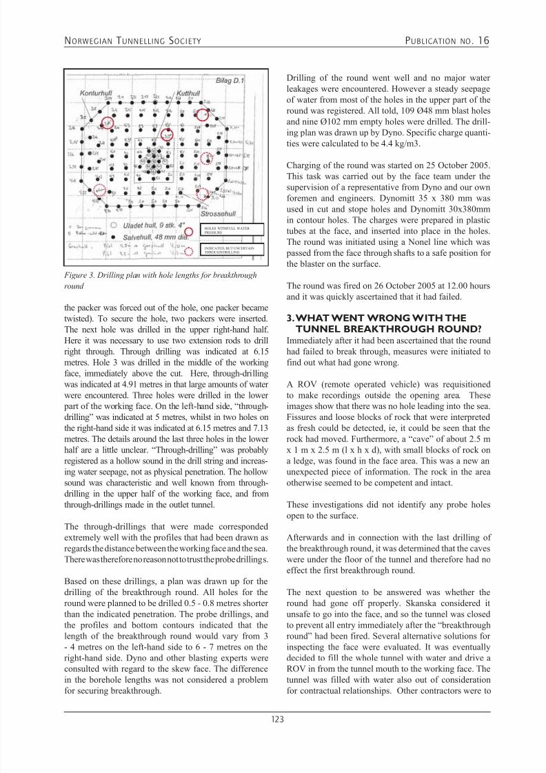
7/21/2019 Publication 16
http://slidepdf.com/reader/full/publication-16 125/181
NORWEGIAN T UNNELLING SOCIETY PUBLICATION NO . 16
123
Figure 3. Drilling plan with hole lengths for breakthrough
round
HOLES WITHFULL WATER
PRESSURE
INDICATED, BUT UNCERTAIN
THROUGH DRILLING
the packer was forced out of the hole, one packer becametwisted). To secure the hole, two packers were inserted.The next hole was drilled in the upper right-hand half.Here it was necessary to use two extension rods to drillright through. Through drilling was indicated at 6.15metres. Hole 3 was drilled in the middle of the workingface, immediately above the cut. Here, through-drillingwas indicated at 4.91 metres in that large amounts of waterwere encountered. Three holes were drilled in the lower
part of the working face. On the left-hand side, “through-drilling” was indicated at 5 metres, whilst in two holes onthe right-hand side it was indicated at 6.15 metres and 7.13metres. The details around the last three holes in the lowerhalf are a little unclear. “Through-drilling” was probablyregistered as a hollow sound in the drill string and increas-ing water seepage, not as physical penetration. The hollowsound was characteristic and well known from through-drilling in the upper half of the working face, and fromthrough-drillings made in the outlet tunnel.
The through-drillings that were made corresponded
extremely well with the profiles that had been drawn asregards the distance between the working face and the sea.There was therefore no reason not to trust the probe drillings.
Based on these drillings, a plan was drawn up for thedrilling of the breakthrough round. All holes for theround were planned to be drilled 0.5 - 0.8 metres shorterthan the indicated penetration. The probe drillings, andthe profiles and bottom contours indicated that thelength of the breakthrough round would vary from 3- 4 metres on the left-hand side to 6 - 7 metres on theright-hand side. Dyno and other blasting experts wereconsulted with regard to the skew face. The difference
in the borehole lengths was not considered a problemfor securing breakthrough.
Drilling of the round went well and no major waterleakages were encountered. However a steady seepageof water from most of the holes in the upper part of theround was registered. All told, 109 Ø48 mm blast holesand nine Ø102 mm empty holes were drilled. The drill-
ing plan was drawn up by Dyno. Specific charge quanti-ties were calculated to be 4.4 kg/m3.
Charging of the round was started on 25 October 2005.This task was carried out by the face team under thesupervision of a representative from Dyno and our ownforemen and engineers. Dynomitt 35 x 380 mm wasused in cut and stope holes and Dynomitt 30x380mmin contour holes. The charges were prepared in plastictubes at the face, and inserted into place in the holes.The round was initiated using a Nonel line which was passed from the face through shafts to a safe position forthe blaster on the surface.
The round was fired on 26 October 2005 at 12.00 hoursand it was quickly ascertained that it had failed.
3. WHAT WENT WRONG WITH THETUNNEL BREAKTHROUGH ROUND?
Immediately after it had been ascertained that the roundhad failed to break through, measures were initiated tofind out what had gone wrong.
A ROV (remote operated vehicle) was requisitionedto make recordings outside the opening area. These
images show that there was no hole leading into the sea.Fissures and loose blocks of rock that were interpretedas fresh could be detected, ie, it could be seen that therock had moved. Furthermore, a “cave” of about 2.5 mx 1 m x 2.5 m (l x h x d), with small blocks of rock ona ledge, was found in the face area. This was a new anunexpected piece of information. The rock in the areaotherwise seemed to be competent and intact.
These investigations did not identify any probe holesopen to the surface.
Afterwards and in connection with the last drilling ofthe breakthrough round, it was determined that the caveswere under the floor of the tunnel and therefore had noeffect the first breakthrough round.
The next question to be answered was whether theround had gone off properly. Skanska considered itunsafe to go into the face, and so the tunnel was closedto prevent all entry immediately after the “breakthroughround” had been fired. Several alternative solutions forinspecting the face were evaluated. It was eventuallydecided to fill the whole tunnel with water and drive aROV in from the tunnel mouth to the working face. The
tunnel was filled with water also out of considerationfor contractual relationships. Other contractors were to

7/21/2019 Publication 16
http://slidepdf.com/reader/full/publication-16 126/181
NORWEGIAN T UNNELLING SOCIETY PUBLICATION NO . 16
124
start work in neighbouring areas and were dependentupon being able to work in safety. As long as the tunnelwas not filled with water, a sudden collapse could resultin the flooding of areas where crews were to work. Ofcourse, this was not acceptable.
Whilst the tunnel was being filled with water, a moreextensive ROV investigation was carried out to find probe boreholes in the piercing area. This equipmenthad positioning means, and the area around the pierc-ing site was searched. Only one probe hole was foundduring this investigation. A measuring-in of the rocksurface was carried out to compare these data with exist-ing bottom contour maps. Small differences were foundin areas where the rock surface was sloping. However,in the steep portion in front of the breakthrough area,a difference of an approximately 1-metre long defined profile was found.
The ROV investigation inside the tunnel went smoothly.About 1,300 metres of cable were rolled out before theworking face and the round could be filmed. Sonarimages were taken so that the length of the round thathad been fired could be determined. Measurements ofdebris and the length of the round indicated that theround had gone as planned. The debris lay mainly on theleft-hand side of the working face and 20 metres back-
Figure 4. Working face measured in prior to firing the breakthrough round (green). Estimated position of working face after the
breakthrough round (purple)
ESTIMATED
POSITION OF
WORKING FACE
WORKING FACE
PRIOR TO
BREAKTHROUGH
wards (sighting direction towards the working face). Atthe right hand side, there was a smaller mass about 15metres back from the face.
Based on these observations and the measurements
made at this stage, it was concluded that there was prob-ably still 1.5 - 3 metres of rock before breakthrough (seeFigure 4).
4. CHOICE OF METHOD FORENSURING BREAKTHROUGH
We found ourselves in a new and unfamiliar situation.A number of methods to ensure breakthrough wereevaluated:• Use of additional charges This was considered unsafe, since the thickness of the
remaining rock plug was not known with sufficientcertainty.
• Drilling through a casing with heavy drilling equip-ment mounted on a barge.
This method was considered the most appropriatefor a long time. Project planning and the ordering ofequipment were well underway. However, after a moredetailed feasibility analysis, the method was aban-doned.
• Drilling with land-based drilling equipment mount-ed on a tool carrier on the seafloor
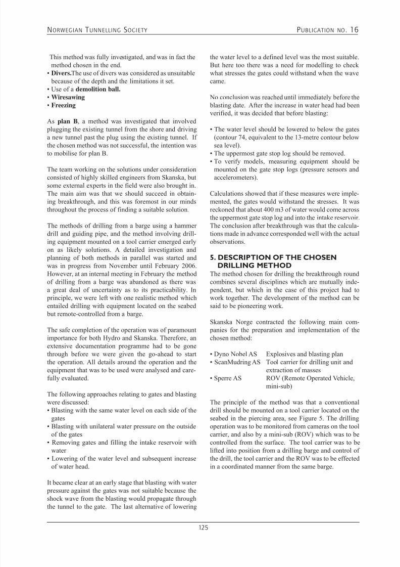
7/21/2019 Publication 16
http://slidepdf.com/reader/full/publication-16 127/181
NORWEGIAN T UNNELLING SOCIETY PUBLICATION NO . 16
125
This method was fully investigated, and was in fact themethod chosen in the end.
• Divers. The use of divers was considered as unsuitable because of the depth and the limitations it set.
• Use of a demolition ball.
• Wiresawing• Freezing
As plan B, a method was investigated that involved plugging the existing tunnel from the shore and drivinga new tunnel past the plug using the existing tunnel. Ifthe chosen method was not successful, the intention wasto mobilise for plan B.
The team working on the solutions under considerationconsisted of highly skilled engineers from Skanska, butsome external experts in the field were also brought in.The main aim was that we should succeed in obtain-ing breakthrough, and this was foremost in our mindsthroughout the process of finding a suitable solution.
The methods of drilling from a barge using a hammerdrill and guiding pipe, and the method involving drill-ing equipment mounted on a tool carrier emerged earlyon as likely solutions. A detailed investigation and planning of both methods in parallel was started andwas in progress from November until February 2006.However, at an internal meeting in February the methodof drilling from a barge was abandoned as there wasa great deal of uncertainty as to its practicability. In
principle, we were left with one realistic method whichentailed drilling with equipment located on the seabed but remote-controlled from a barge.
The safe completion of the operation was of paramountimportance for both Hydro and Skanska. Therefore, anextensive documentation programme had to be gonethrough before we were given the go-ahead to startthe operation. All details around the operation and theequipment that was to be used were analysed and care-fully evaluated.
The following approaches relating to gates and blastingwere discussed:• Blasting with the same water level on each side of the
gates• Blasting with unilateral water pressure on the outside
of the gates• Removing gates and filling the intake reservoir with
water • Lowering of the water level and subsequent increase
of water head.
It became clear at an early stage that blasting with water pressure against the gates was not suitable because the
shock wave from the blasting would propagate throughthe tunnel to the gate. The last alternative of lowering
the water level to a defined level was the most suitable.But here too there was a need for modelling to checkwhat stresses the gates could withstand when the wavecame.
No conclusion was reached until immediately before the blasting date. After the increase in water head had beenverified, it was decided that before blasting:
• The water level should be lowered to below the gates(contour 74, equivalent to the 13-metre contour belowsea level).
• The uppermost gate stop log should be removed.• To verify models, measuring equipment should be
mounted on the gate stop logs (pressure sensors andaccelerometers).
Calculations showed that if these measures were imple-mented, the gates would withstand the stresses. It wasreckoned that about 400 m3 of water would come acrossthe uppermost gate stop log and into the intake reservoir.The conclusion after breakthrough was that the calcula-tions made in advance corresponded well with the actualobservations.
5. DESCRIPTION OF THE CHOSENDRILLING METHOD
The method chosen for drilling the breakthrough roundcombines several disciplines which are mutually inde- pendent, but which in the case of this project had to
work together. The development of the method can besaid to be pioneering work.
Skanska Norge contracted the following main com- panies for the preparation and implementation of thechosen method:
• Dyno Nobel AS Explosives and blasting plan• ScanMudring AS Tool carrier for drilling unit and
extraction of masses• Sperre AS ROV (Remote Operated Vehicle,
mini-sub)
The principle of the method was that a conventionaldrill should be mounted on a tool carrier located on theseabed in the piercing area, see Figure 5. The drillingoperation was to be monitored from cameras on the toolcarrier, and also by a mini-sub (ROV) which was to becontrolled from the surface. The tool carrier was to belifted into position from a drilling barge and control ofthe drill, the tool carrier and the ROV was to be effectedin a coordinated manner from the same barge.
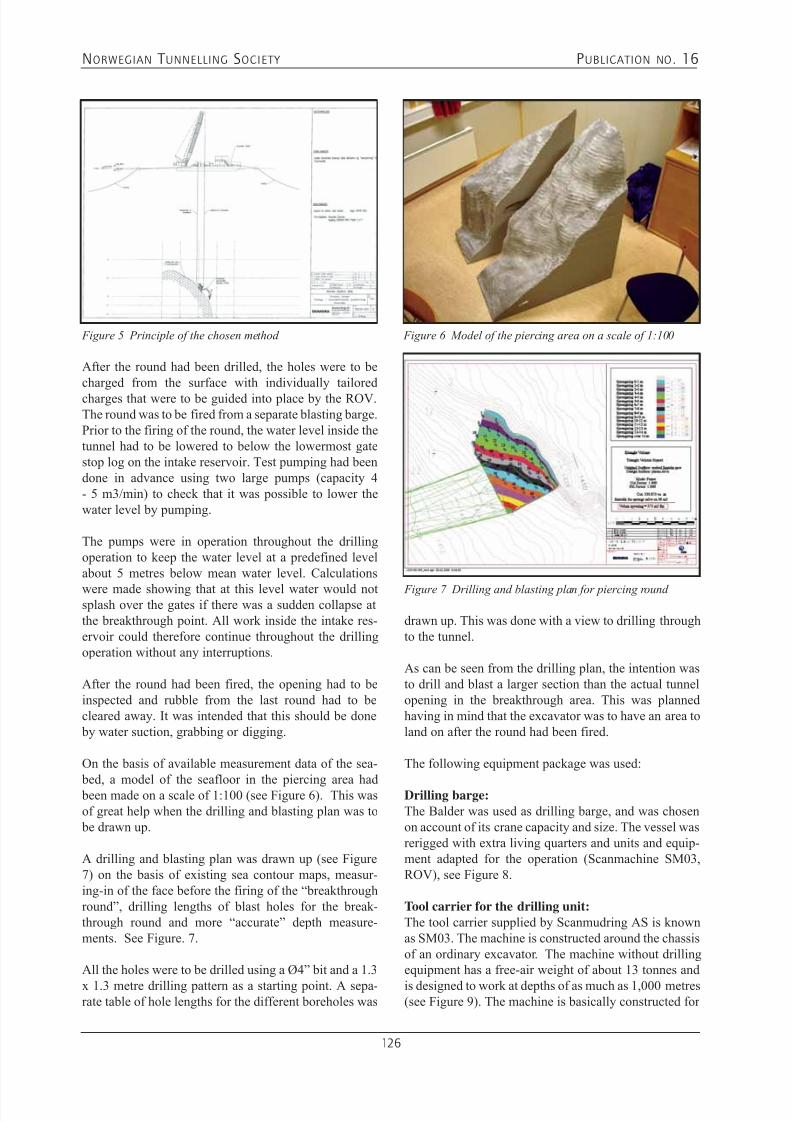
7/21/2019 Publication 16
http://slidepdf.com/reader/full/publication-16 128/181
NORWEGIAN T UNNELLING SOCIETY PUBLICATION NO . 16
126
After the round had been drilled, the holes were to becharged from the surface with individually tailoredcharges that were to be guided into place by the ROV.The round was to be fired from a separate blasting barge.Prior to the firing of the round, the water level inside thetunnel had to be lowered to below the lowermost gatestop log on the intake reservoir. Test pumping had beendone in advance using two large pumps (capacity 4- 5 m3/min) to check that it was possible to lower thewater level by pumping.
The pumps were in operation throughout the drillingoperation to keep the water level at a predefined levelabout 5 metres below mean water level. Calculations
were made showing that at this level water would notsplash over the gates if there was a sudden collapse atthe breakthrough point. All work inside the intake res-ervoir could therefore continue throughout the drillingoperation without any interruptions.
After the round had been fired, the opening had to beinspected and rubble from the last round had to becleared away. It was intended that this should be done by water suction, grabbing or digging.
On the basis of available measurement data of the sea-
bed, a model of the seafloor in the piercing area had been made on a scale of 1:100 (see Figure 6). This wasof great help when the drilling and blasting plan was to be drawn up.
A drilling and blasting plan was drawn up (see Figure7) on the basis of existing sea contour maps, measur-ing-in of the face before the firing of the “breakthroughround”, drilling lengths of blast holes for the break-through round and more “accurate” depth measure-ments. See Figure. 7.
All the holes were to be drilled using a Ø4” bit and a 1.3
x 1.3 metre drilling pattern as a starting point. A sepa-rate table of hole lengths for the different boreholes was
Figure 5 Principle of the chosen method Figure 6 Model of the piercing area on a scale of 1:100
drawn up. This was done with a view to drilling throughto the tunnel.
As can be seen from the drilling plan, the intention wasto drill and blast a larger section than the actual tunnelopening in the breakthrough area. This was plannedhaving in mind that the excavator was to have an area toland on after the round had been fired.
The following equipment package was used:
Drilling barge:The Balder was used as drilling barge, and was chosenon account of its crane capacity and size. The vessel wasrerigged with extra living quarters and units and equip-ment adapted for the operation (Scanmachine SM03,ROV), see Figure 8.
Tool carrier for the drilling unit:The tool carrier supplied by Scanmudring AS is knownas SM03. The machine is constructed around the chassisof an ordinary excavator. The machine without drillingequipment has a free-air weight of about 13 tonnes and
is designed to work at depths of as much as 1,000 metres(see Figure 9). The machine is basically constructed for
Figure 7 Drilling and blasting plan for piercing round

7/21/2019 Publication 16
http://slidepdf.com/reader/full/publication-16 129/181
NORWEGIAN T UNNELLING SOCIETY PUBLICATION NO . 16
127
Figure 8 Rig plan for the Balder
digging and dredging on the seafloor, but for this projectit was modified to be able to carry the drilling unit. Toenable the tool carrier to work in steep terrain with a fallof 45 - 600 without tipping over, it had to have rigid sup- port legs welded onto the front (see Figure 10).
Figure 9 The SM03 tool carrier for the drilling unit.
The SM03 was also to be used to dredge or dig out themasses remaining after the last round once the break-through round had been fired. Scanmudring AS had itsown crew who operated this machine.
Figure 10 Lowering of SM03 with drilling unit
Drill:A standard drill of the Montabert HC 40 type was used.A thorough check of the equipment was made, andcritical seals and points at which it was undesirableto have water ingress, were greased and sealed. There
was a reserve drill that could be used in the event of a breakdown. Hydraulic hoses were extended and passedup to the deck of the barge. They were kept floating inthe sea by floats.
It was decided to drill using a Ø4” pointed bit and anextension rod. Maximum drilling depth for the equip-ment was therefore about 7.4 metres.
ROV (Remote Operated Vehicle):Sperre AS provided a ROV and a crew to operate it.The ROV was of vital importance throughout the opera-tion as it was used to monitor the work. It had to be inservice in basically all operations that took place underwater. The danger of entanglement with cables, anchorchains and, later on, charge hoses was considerable. Theequipment used was a Subfighter 7500 with installedsonar (see Figure 11). Apart from being used to “see”,the ROV was also used to move slings on support bolts,to install funnels for the subsequent charging operationand, during the charging operation, to guide the chargesinto place.
Figure 11 ROV Subfighter 7500
Tripod:Because the rock surface outside the opening area hada fall of from 45 - 70o, it was impossible to get thetool carrier with drilling equipment to stand stably onthe seafloor during the drilling operation. A number ofalternatives were evaluated. A solution that involvedestablishing support bolts on the ridge above the pierc-ing site was considered the optimal solution. To drillholes for the bolts, a tripod fitted with a drill hammertaken from a Commando 300 rig was constructed (see
Figure 12). The tripod had legs that could be adjusted tothe fall of the rock. Two locating points were identified

7/21/2019 Publication 16
http://slidepdf.com/reader/full/publication-16 130/181
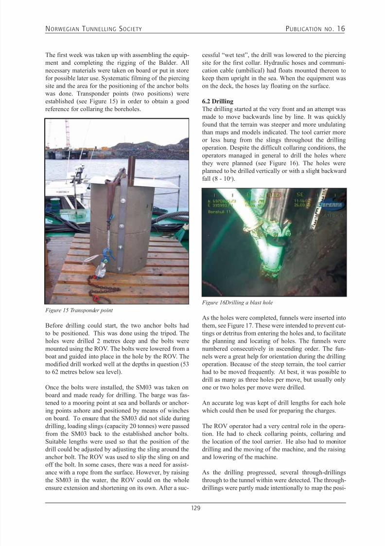
7/21/2019 Publication 16
http://slidepdf.com/reader/full/publication-16 131/181
NORWEGIAN T UNNELLING SOCIETY PUBLICATION NO . 16
129
The first week was taken up with assembling the equip-ment and completing the rigging of the Balder. Allnecessary materials were taken on board or put in storefor possible later use. Systematic filming of the piercingsite and the area for the positioning of the anchor bolts
was done. Transponder points (two positions) wereestablished (see Figure 15) in order to obtain a goodreference for collaring the boreholes.
Figure 15 Transponder point
Before drilling could start, the two anchor bolts hadto be positioned. This was done using the tripod. Theholes were drilled 2 metres deep and the bolts weremounted using the ROV. The bolts were lowered from a boat and guided into place in the hole by the ROV. Themodified drill worked well at the depths in question (53to 62 metres below sea level).
Once the bolts were installed, the SM03 was taken on board and made ready for drilling. The barge was fas-tened to a mooring point at sea and bollards or anchor-ing points ashore and positioned by means of wincheson board. To ensure that the SM03 did not slide duringdrilling, loading slings (capacity 20 tonnes) were passedfrom the SM03 back to the established anchor bolts.Suitable lengths were used so that the position of thedrill could be adjusted by adjusting the sling around theanchor bolt. The ROV was used to slip the sling on andoff the bolt. In some cases, there was a need for assist-ance with a rope from the surface. However, by raising
the SM03 in the water, the ROV could on the wholeensure extension and shortening on its own. After a suc-
cessful “wet test”, the drill was lowered to the piercingsite for the first collar. Hydraulic hoses and communi-cation cable (umbilical) had floats mounted thereon tokeep them upright in the sea. When the equipment wason the deck, the hoses lay floating on the surface.
6.2 DrillingThe drilling started at the very front and an attempt wasmade to move backwards line by line. It was quicklyfound that the terrain was steeper and more undulatingthan maps and models indicated. The tool carrier moreor less hung from the slings throughout the drillingoperation. Despite the difficult collaring conditions, theoperators managed in general to drill the holes wherethey were planned (see Figure 16). The holes were planned to be drilled vertically or with a slight backwardfall (8 - 10o).
Figure 16 Drilling a blast hole
As the holes were completed, funnels were inserted intothem, see Figure 17. These were intended to prevent cut-tings or detritus from entering the holes and, to facilitatethe planning and locating of holes. The funnels werenumbered consecutively in ascending order. The fun-nels were a great help for orientation during the drillingoperation. Because of the steep terrain, the tool carrierhad to be moved frequently. At best, it was possible to
drill as many as three holes per move, but usually onlyone or two holes per move were drilled.
An accurate log was kept of drill lengths for each holewhich could then be used for preparing the charges.
The ROV operator had a very central role in the opera-tion. He had to check collaring points, collaring andthe location of the tool carrier. He also had to monitordrilling and the moving of the machine, and the raisingand lowering of the machine.
As the drilling progressed, several through-drillings
through to the tunnel within were detected. The through-drillings were partly made intentionally to map the posi-

7/21/2019 Publication 16
http://slidepdf.com/reader/full/publication-16 132/181
NORWEGIAN T UNNELLING SOCIETY PUBLICATION NO . 16
130
Figure 17 Funnels for marking boreholes
tion of the tunnel and were partly unintentional. Holes
that were drilled right through were plugged with steelcones to reduce inleakages into the tunnel, see Figure18. The shortest drilling length during the through-drill-ing was about 1 metre (in the roof of the tunnel).
Figure 18 Steel cones for plugging boreholes that were
drilled right through
Based on the new information that gradually came tolight, a revision of the drilling plan was made. It wasdecided not to go as far out to the left as planned, see
Figure 19. The through-drillings indicated that the faceof the tunnel was quite close to the breakthrough point.
By drilling further back in the roof of the tunnel, itwould be possible to land the SM03 inside the tunnelinstead. This also gave a reduction in the number ofholes drilled.
Figure 19 Plan for the fully drilled piercing round
In the period 24 March - 30 March a total of 39 holeshaving a length of from 1.2 metres to 7.6 metres weredrilled. All told, 127.6 metres were drilled.
6.3 ChargingPrior to the start of charging, all holes that were to becharged were logged and cleared of any cuttings orcrabs. For each hole, charges were prepared in 76 mmdiameter PEH plastic tubes with lengths adapted to the
length of the boreholes. The tubes had a tip welded on atthe ends to facilitate entry into the funnels or boreholes.The charges were prepared on the deck of the Balder ina typical production line operation. The charges werelowered down using 6mm diameter floating rope to adefined depth. At that depth, the ROV was waiting toguide the charges into the hole. The charging startedat the back of the round. This was to prevent the ROVfrom becoming entangled with the charge lines. With 2- 3 lines from each hole, this became in time a ratherdemanding operation, see Figure 20

7/21/2019 Publication 16
http://slidepdf.com/reader/full/publication-16 133/181
NORWEGIAN T UNNELLING SOCIETY PUBLICATION NO . 16
131
Once a charge had been placed in the holes, the Nonellines were passed back to a blasting barge and fastenedto numbered pegs corresponding to holes on the bottom,see Figure 21.
Figure 20 Charging boreholes
Figure 21 Blasting barge
With a few exceptions, the charging of the holes took place without any problems. The charging was startedin the evening of 31 March (2010 hours) and the lasthole was charged on 1 April (1202 hours). A total of 32holes were charged with a total explosive quantity of
493 kg. The round was fired at 1900 hours on Saturday1 April 2006. This time water appeared as expected.
The reason for not firing the round immediately thecharging was completed was related to calculationsmade prior to the firing. These calculations showed thatthe round ought to be fired at low tide to reduce the loadon the gates as much as possible.
After the round had been fired, 60 seconds passed before we heard that the water began to rise in theintake reservoir. The water rose steadily until it ran overthe gate after about three minutes. It seemed as though
the water came in two pulses, first a gentle pulse andthen a more powerful one. The water flowed over the
gates for about one minute before gently drawing back.After about eight minutes the water column had settledcompletely.
6.4 Finishing operations
After the round had been fired and the water had cleared,a ROV investigation of the piercing area was made. Theinspection revealed that the blasting operation had beensuccessful. It showed that between 1 - 2 metres of rockmass remained before the first breakthrough round had broken through. There was extremely little rock coverin the left half of the roof seen in the order of ascendingchainage number. The margins had clearly not been inour favour.
There were very few large rocks in the old rubbleand much of the old rubble had been blasted away.However, some rock removal was required in order toobtain sufficient opening (20 m2 over a length of about5 metres). The Balder was therefore rerigged to take agrab and the SM03 with dredging equipment. Somegrabbing was done and the SM03 used blades on themachine and suction equipment to remove some of themass in the actual tunnel mouth.
Once this work had been completed and sonar scanningof the entrance portion with a ROV had been done, the job was considered to be finished. The equipment wastaken ashore and demobilised.
The on-site operation was carried out in the period from13 March - 4 April 2006. This was well within the over-all time schedule allowed. However, the planning of theoperation had been underway since 26 October 2005.
7. CONCLUSIONSThe reasons we found ourselves having to implementextraordinary measures in order to achieve break-through are many.
The most obvious reason is that the blast holes in the breakthrough round were not drilled long enough in
critical areas. The cut had not managed to break throughto the sea and create the necessary opening to allow therest of the round to break through as planned. This inturn was connected to the fact that the number of certainthrough-drillings to the sea had been too small to be ableto form a reliable picture of the rock surface beyond.The insufficient number of through-drillings had both a practical and a psychological cause. With a pressure of8 bar it is difficult to get packers into the borehole. Thecrew at the working face knew that we would be facedwith a serious problem if the drilling caused leakageswhich could not be sealed. Naturally, this meant thatthe face crew was reluctant to make too many through-
drillings.
7/21/2019 Publication 16
http://slidepdf.com/reader/full/publication-16 134/181
NORWEGIAN T UNNELLING SOCIETY PUBLICATION NO . 16
132
On the basis of the data we had from the ROV investiga-tion, sectional drawings and drill-through lengths whichwere identical with sectional drawings, we believedthat we had an adequate picture of the seabed topogra- phy. Experience has shown that the accuracy of map
documentation is crucial. In steep terrain and at greatdepths it is difficult to produce good depth charts. Thisis something that requires more attention.
Another reason that the breakthrough round failed may be the rock quality. The rock in the area is hard, darkand solid amphibolitic gneiss with cross foliation (60 -80o) which crosses the tunnel axis in a gentle diagonal.Later ROV observations showed that the rock had freshfissures and cracks after the blasting, which may suggestthat the rock mass had been about to collapse. However,the external pressure had been too great to allow themass to be blown out and given the required opening,and a situation involving a sort of lid effect had thusarisen. As the tunnel is horizontal, we were not helped by gravity during the blasting. If the tunnel piercing had been more upwardly directed, the outcome may have been different.
Based on the ROV observations made after the success-ful breakthrough round on 1 April 2006, and observa-tions made during the drilling of the breakthrough round,it is clear that the margins were not in our favour.
When we found ourselves confronted by a failed break-through, we were in a situation that was anything butdesirable. However, it has been impressive to see thecreativity and enthusiasm on site to find solutions tocomplex problems. Cross-discipline cooperation hasturned a fiasco into a success. The development of themethod has been pioneering work, and Skanska hasshown that it is possible to succeed.
8. FINANCESAn operation of this kind, involving a large number of people, disciplines and equipment has a price tag. Thetotal cost of the operation came to NOK 18 - 20 million.It is therefore not a solution that will be first choice for breakthrough, even though from a safety point of viewit can be deemed a success. The method has at least proven to be practicable.
Protan AS
P.O. Box 420 Brakerøya
NO-3002 Drammen, Norway
Tel. +47 32 22 16 00
Fax +47 32 22 17 00
www.protan.com
58 years of experience
on the world market
58 years of knowledge
about the fabric
58 years of co-operation
with the biggest
contractors in the world
•
•
•Quality Ventilation Ducting

7/21/2019 Publication 16
http://slidepdf.com/reader/full/publication-16 135/181
NORWEGIAN T UNNELLING SOCIETY PUBLICATION NO . 16
133
9.1 NORWEGIAN HIGH PRESSURE CONCRETE PLUGS
Jan Bergh-Christensen
Einar Broch
ABSTRACT: A study on design, construction and operation of high pressure plugs was carried in the period from 1987 to1991. Details of more than 30 plugs with static pres-
sure head up to about 1,000 meters were collected and analysed. While the concrete length varies from 2 to 5 % of the static water pressure, the steel lining may be as short as 0.4 % of the water pressure head.
INTRODUCTIONA research project to document and analyse gainedexperience in the design, construction and operation ofhigh pressure concrete plugs in Norwegian hydro power plants was carried out. The purpose was to evaluate the
technology, and to develop guidelines of good practisein the planning and construction of concrete plugs forhigh pressure gas storage caverns.
Information of about 150 concrete plugs was collected.The data base includes some 30 plugs with water headsabove 400 meters constructed during the period 1970 -1990. During the 1980’s, many high pressure plugs wereconstructed for static water head up to 1,000 meters.The study was concentrated to the newest plugs whichwere designed and constructed in line with improvedquality standards and grouting technology. The newer plugs were more expensive, but also more efficient interms of reduced leakage as compared to older cement-grouted plugs.
SITE WATER HEAD1
m
YEAR CROSSSECTIONm2
LENGTHCONCRETEm
LENGTHSTEELm
WATER LEAKAGEl/min
NYSET-STEGGJE 964 1987 25 55 Penstock < 60TJODAN 880 1984 17 45 Penstock 2TAFJORD K5 790 1982 18 88 Penstock 503)
SKARJE 765 1986 252 20 5.5 < 153)
MEL 740 1989 22 27 27 13)
SILDVIK 640 1981 26 35 12 < 240JOSTEDALEN 622 1989 35 20 5 63)
LOMI 565 1978 20 15 9.5 190LANG-SIMA 520 1980 30 50 Penstock 120
SØRFJORD 505 1983 20 20 12 103)
KVILLDAL 465 1982 31 30 4 4)
TORPA 455 1989 32 20 6 < 13)
EIKELANDSOSEN 455 1986 20 20 5 8STEINSLAND 454 1980 20 20 10.2 4)
KOLSVIK 449 1979 23 20 10 30SKIBOTN 445 1979 18 12 7.6 963)
LEIRDØLA 441 1978 26 30 Penstock < 54SAURDAL 410 1985 49 40 1.5 53) ORMSETFOSS 373 1988 22 22 7 < 3DIVIDALEN 295 1972 10 13 4.5 < 120
Table 1: Key figures for some major plugs.
1) Max. static head 2) Varies from 20 to 30 m2 3) Remedial grouting at first water filling or later 4) Within accepted limits
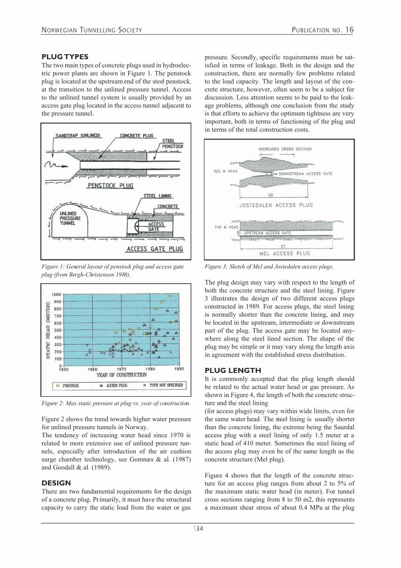
7/21/2019 Publication 16
http://slidepdf.com/reader/full/publication-16 136/181
NORWEGIAN T UNNELLING SOCIETY PUBLICATION NO . 16
134
PLUG TYPESThe two main types of concrete plugs used in hydroelec-tric power plants are shown in Figure 1. The penstock plug is located at the upstream end of the steel penstock,at the transition to the unlined pressure tunnel. Access
to the unlined tunnel system is usually provided by anaccess gate plug located in the access tunnel adjacent tothe pressure tunnel.
Figure 2: Max static pressure at plug vs. year of construction.
Figure 1: General layout of penstock plug and access gate
plug (from Bergh-Christensen 1988).
Figure 2 shows the trend towards higher water pressurefor unlined pressure tunnels in Norway.The tendency of increasing water head since 1970 isrelated to more extensive use of unlined pressure tun-nels, especially after introduction of the air cushionsurge chamber technology, see Gomnæs & al. (1987)and Goodall & al. (1989).
DESIGNThere are two fundamental requirements for the design
of a concrete plug. Primarily, it must have the structuralcapacity to carry the static load from the water or gas
pressure. Secondly, specific requirements must be sat-isfied in terms of leakage. Both in the design and theconstruction, there are normally few problems relatedto the load capacity. The length and layout of the con-crete structure, however, often seem to be a subject for
discussion. Less attention seems to be paid to the leak-age problems, although one conclusion from the studyis that efforts to achieve the optimum tightness are veryimportant, both in terms of functioning of the plug andin terms of the total construction costs.
Figure 3: Sketch of Mel and Jostedalen access plugs.
The plug design may vary with respect to the length of both the concrete structure and the steel lining. Figure
3 illustrates the design of two different access plugsconstructed in 1989. For access plugs, the steel liningis normally shorter than the concrete lining, and may be located in the upstream, intermediate or downstream part of the plug. The access gate may be located any-where along the steel lined section. The shape of the plug may be simple or it may vary along the length axisin agreement with the established stress distribution.
PLUG LENGTHIt is commonly accepted that the plug length should be related to the actual water head or gas pressure. As
shown in Figure 4, the length of both the concrete struc-ture and the steel lining(for access plugs) may vary within wide limits, even forthe same water head. The steel lining is usually shorterthan the concrete lining, the extreme being the Saurdalaccess plug with a steel lining of only 1.5 meter at astatic head of 410 meter. Sometimes the steel lining ofthe access plug may even be of the same length as theconcrete structure (Mel plug).
Figure 4 shows that the length of the concrete struc-ture for an access plug ranges from about 2 to 5% ofthe maximum static water head (in meter). For tunnel
cross sections ranging from 8 to 50 m2, this representsa maximum shear stress of about 0.4 MPa at the plug

7/21/2019 Publication 16
http://slidepdf.com/reader/full/publication-16 137/181
NORWEGIAN T UNNELLING SOCIETY PUBLICATION NO . 16
135
Figure 4: Length of steel lining and concrete structure vs.
static water head.
circumferential area, assuming a uniform shear distribu-tion in the rock to concrete interface. This used to be themaximum accepted shear stress for uniaxial situationsaccording to former standards for concrete structures(for uniaxial concrete strength 25 MPa, i.e. C25).
The maximum linear hydraulic gradient along the plugaxis (ratio of water head to concrete length) that may becalculated for a shear stress of 0.4 MPa will be rangingfrom 20 to 50 for the tunnel cross sections in question.This complies with a traditional rule of thumb for plugdesign in Norway, which is based on the assumptionthat higher gradients may lead to unacceptable highleakage. This gradient criterion may be considered radi-
cal. Benson (1989) has for instance suggested that themaximum hydraulic gradient should be as low as 20 formassive, hard and widely jointed rock types.
In reality, the uniform shear distribution presupposed inthis design principle is not valid. Numerical modellingcarried out during the research project showed that theshear stress will be concentrated to the first five metersof the upstream part of the plug (assuming steel gatelocated upstream so that the water pressure is not act-ing from inside the plug structure). The shear stressesrapidly decrease further downstream along the plug.
Therefore, if one considers the actual stress distributionwithin the concrete body as calculated by numericalmethods, relatively short plug lengths could be allowed.In practical design, however, one should also considerthe three dimensional water flow regime and the limita-tions with respect to grouting. In this context, it is theauthors’ opinion that the minimum plug length for high pressure plugs that are supposed to act as water tightconstructions should never be less than five meters.
CONSTRUCTION AND OPERATIONThere has never been reported any plug malfunction orfailure related to overloading in Norwegian hydropower
projects. The only “failure” experienced is unacceptablehigh leakage. Normally, remedial grouting will be car-
ried out during the first water filling or at a later stage.But the criterion for remedial grouting may vary a lotamong the plug owners.
Grouting
A description of the grouting methods for concrete plugshas been presented by Bergh-Christensen (1988). Thequality and the extent of rock and concrete groutingare of great importance both for the final constructioncosts and the leakages at the plug. This is illustrated inFigure 5, in which the construction costs are given forthe two plugs shown in Figure 3. As can be seen, thegrouting costs are in the order of about 40 to 45% ofthe construction costs for both plugs (both constructedin 1989). Grouting of the rock mass prior to concretingworks amounts to about 10 % of the total cost. Remedialgrouting during or after the water filling of the tunnel,accounts for another 10 %.
Figure 5: Construction costs for Mel and Jostedalen access
plugs (in million Norwegian kroner and US dollars).
Whereas the steel lining at Mel is 5.5 times longer thanfor Jostedalen, the lining costs were only about 50 %higher. This is due to the more complicated design atJostedalen, in which case especially the gate construc-tion is expensive. The total costs are higher for theJostedalen plug than for the Mel plug, even though theMel plug is longer than the other. The concrete volumes
of the plugs are about 600 m3 and 700 m3 for Mel andJostedalen respectively. The simplicity of the Mel con-struction as compared to Jostedalen is probably the mainreason for the cost differences.
A comparison of grouting costs for several plugs isshown on Figure 6. The costs are actual costs at theyear of construction. At both Jostedalen and Mel, themost modern grouting technique with both polyurethaneand epoxy injection at high pressure through groutinghoses has been used. At Ormsetfoss, this was done at aless ambitious extent. Much of the grout was injectedthrough boreholes immediately before the first water
filling. At Sørfjord, epoxy was not used and all groutingwas done through boreholes.

7/21/2019 Publication 16
http://slidepdf.com/reader/full/publication-16 138/181
NORWEGIAN T UNNELLING SOCIETY PUBLICATION NO . 16
136
Figure 6: Grouting costs for some access plugs.
The consumed grout mass as documented for some plugs is shown in Figure 7. As can be seen, severaltonnes of (fine grained) cement are normally injected.Most of the cement mass is used to fill the voids thatnormally will develop in the contact zone between therock and the concrete at the tunnel roof. If cement grout-ing is neglected or not well performed, large quantitiesof the far more expensive chemicals will be needed.
Figure 7: Grout consumption at some concrete plugs.
Often one will observe that the plug is constructed at thevery latest stage before the power plant is put into oper-ation. The plug construction period must therefore beshort.. The cast concrete temperature will often rise toabout 60 to 70o during the curing period. The plug willthen cool down gradually, but slowly. Efficient groutingmust not take place too early. It must be delayed untilthe concrete temperature has reached an acceptable lowlevel. Because the construction of the plug is on thecritical path of the overall timetable, it is a trend thatgrouting takes place too soon. Both the tightness of the plug and the grouting expenses will suffer. Careful plan-
ning and control with the concrete temperature is thesolution of this problem.
The efficiency of the grouting works is believed to bedependent on the grouting pressure in relation to thewater head and the rock stresses. For several plugs, thegrouting pressure has been considerably higher thanthe water pressure. Figure 8 shows how the grouting
pressure for some plugs is related to the static water pressure.
Figure 8: Grouting pressure vs. static water head.
At Torpa and Sørfjord, the grouting pressure was higherthan the minor principal rock stress as indicated byovercoring measurements. At Torpa, the grouting pres-sure was even higher than the hydraulic jacking pressuremeasured at the plug location.
Leakages
When relating the water leakages to the water head,there apparently is no connection. In theory, the leak-age should decrease with decreasing pressure gradient(Darcy). However, linear regression analysis does notcorrelate the leakage to the hydraulic gradient (Figure9). Nor has there been found any correlation betweenthe leakage and the length of the steel lining or the lineargradient at the steel lining.
Figure 9: Leakage vs. linear hydraulic gradient.
To illustrate the latter, the Saurdal hydropower projectaccess plug, with a steel lining of only 1.5 meter at a

7/21/2019 Publication 16
http://slidepdf.com/reader/full/publication-16 139/181
NORWEGIAN T UNNELLING SOCIETY PUBLICATION NO . 16
137
Figure 10: Leakages at Tjodan (880 meter water head) 1984-
1987.
water head of 410 m (gradient 273) has a leakage of15 l/min. In comparison, the Sildvik hydropower project plug has a leakage of about 240 l/min. at a gradient of 53(water head 640 meter and 12 meter steel lining).
The leakage is best correlated to the year of construction.The modern plugs apparently are better sealed than theolder ones. This is a consequence of the introduction ofhigh pressure chemical grouting in plug construction.
The leakage changes with time. Detailed informationis given from Saurdal, Tjodan and Tafjord. At Saurdal,the leakage was about 140 l/min. after the first filling.Additional grouting by polyurethane at a pressure of 6MPa (410 m water head) through a curtain of drillholesfrom the downstream end about two weeks after fillingreduced the leakage to about 15 l/min. Later on, the leak-age decreased further by 60 to 70% within the next year.
Even stronger reduction of the leakages occurred atTjodan (Figure 10). No remedial grouting has beencarried out. The initial leakage after the first water fill-ing was about 50 l/min., which was reduced to about5 l/min. during the first year of operation. In the nextfour years, the leakage decreased further, and was only
one per cent of the initial leakage at the beginning of1990. During the first seven years of operation, the pres-sure shaft was emptied twice. The owner believes that because of the emptying, suspensions with fine grainedmaterials may have infiltrated the plug and caused theself sealing that have been observed.
CONCLUSIONSAnalysis and observations from the design, constructionand operation of 150 high pressure concrete plugs in Norwegian hydropower projects have shown that the tradi-tional design basis work well. For plugs located in tunnelswith cross sections up to 50 m2 a total plug length between
2 and 5% of the static water head may be recommended.
The final leakage through the plug will to large extentdepend on the quality of the concrete and the groutingwork. Most of the leakage occurs along the rock to con-crete contact zone and mainly in the roof section. Thelayout and design of the concrete and the steel lining
will influence the plug behaviour and hence the extentof the grouting and construction costs.
In conclusion, the current design, construction and groutingtechnique of plugs for Norwegian hydropower plants have proven successful for operational pressures up to 100 Bar.
REFERENCESBenson, R.P. 1989. Design of Unlined and LinedPressure Tunnels. Tunnelling and Underground SpaceTechnology, Vol. 4, No. 2: 155-170.
Bergh-Christensen, J. 1988. Design of high pressureconcrete plugs for hydropower projects. Int. Symp. OnRock Mechanics and Power Plants, Madrid: 261-268.
Broch, E. 1988. Unlined High Pressure Tunnels and AirCushion Surge Chambers. Proc Int. Symp. Tunnellingfor Water Resources and Power Projects. New Delhi,India: 10.
Goodall, D.C., Kjørholt, H., Dahlø, T.S. & Broch,E. 1989. High pressure air cushion surge chambers.Int. Conf. on Progress and Innovation in Tunnelling,Toronto 337-346.
Gomnæs, P.Chr., Myrset, Ø. & Fleicher, E. 1987. Theart of Norwegian hydropower design. Proc. of the Int.Conf. on Hydropower in Oslo, Tapir publishers: 43-54.
Palmstrøm, A., and Schanche, K. 1987. Design featuresat Tjodan save time and money. Water Power & DamConstruction, June: 6 p.
Palmstrøm, A. 1987. Norwegian design and constructionexperiences of unlined pressure shafts and tunnels. Proc. of theInt. Conf. on Hydropower in Oslo, Tapir publishers: 87-99.
Selmer-Olsen, R. 1985. Experience gained from unlinedhigh pressure tunnels and shafts in hydroelectric powerstations in Norway. Norwegian Soil and Rock Eng.Association, Pub. 3, Norwegian Hydropower Tunnelling,Tapir publishers: 31-40.
Tore S.Dahlø, Jan Bergh Christensen and Einar Broch.1992. A review of Norwegian high pressure concrete plugs. Hydropower `92, Broch & Lysne (eds.), 1992,Balkema, Rotterdam, ISBN 9054100540
(The present paper is re-written and condensed, but
contains basically the same results as in above men-tioned Hydropower 92 paper)
7/21/2019 Publication 16
http://slidepdf.com/reader/full/publication-16 140/181
NORWEGIAN T UNNELLING SOCIETY PUBLICATION NO . 16
138
Main product areas:• A broad selection of products for use in underground
technology and construction
• Additives to modify the properties of concrete and mortar
• Complete systems for repair, rehabilitation and finishing ofconcrete, masonry and renders
• Products for treatment and levelling of floors in buildingswithin trade and industry
• Products for soundproofing of domestic and office buildings
• Products for waterproofing, injection and protection of concrete
• Recommended product systems for wetroom applications
• Adhesives and sealants for ceramic tiles and natural stoneware
• Adhesives for all types of floor and wall coverings
Rescon Mapei AS is part of the Mapei Group, which was founded in 1937.
Rescon Mapei AS has worked in Norway and the Nordic countries since 1976.
Mapei is represented in more than 80 countries and has 43 factories spread around the whole
world. The Mapei Group has nearly 4000 employees and a turnover of approx. NOK 10 billion.
Mapei has 7 research centres of which one is at Rescon Mapei in Nord-Odal. 5% of the
turnover is spent on R&D, and 12% of the employees work in research and development.
Rescon Mapei
Rescon Mapei AS - Vallsetvegen 6, N-2120 Sagstua
Tel: +47 62 97 20 00 - Fax: +47 62 97 20 99 - E-mail: [email protected]
www.resconmapei.com
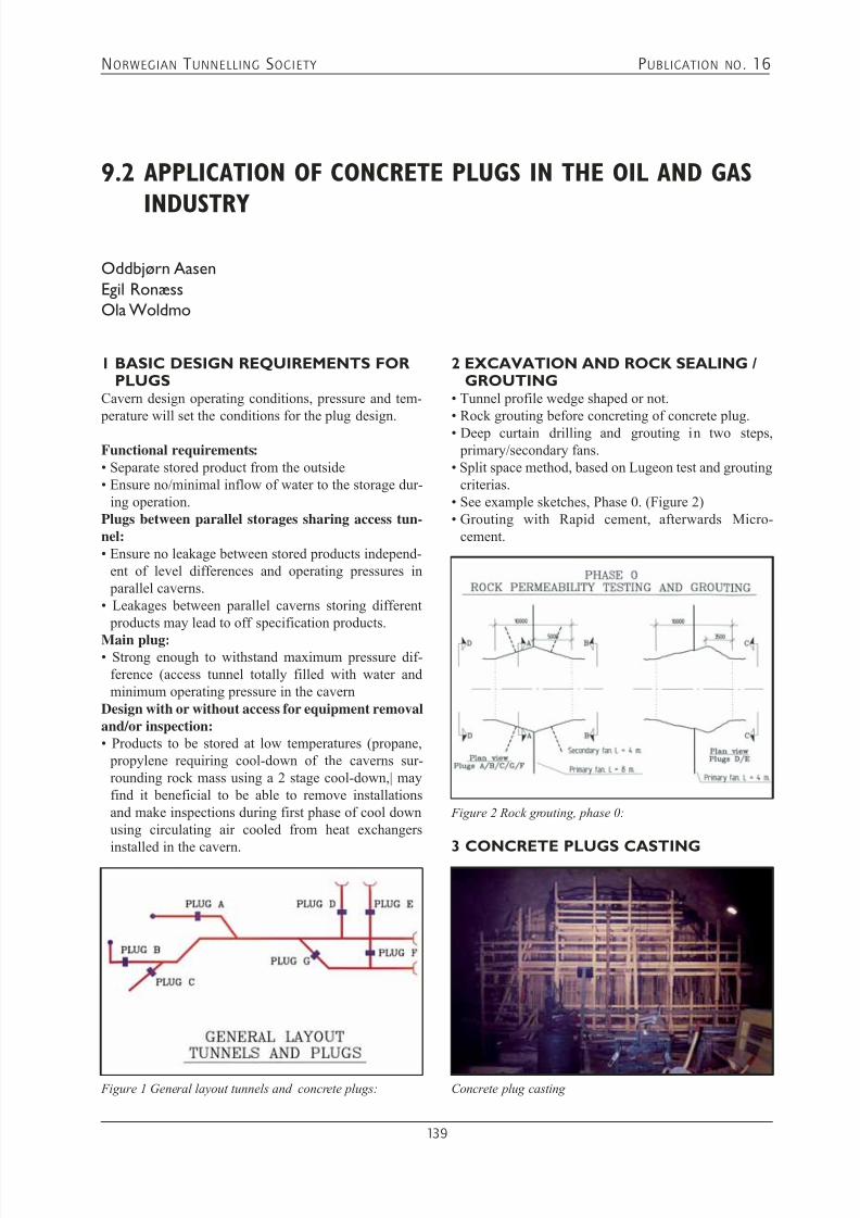
7/21/2019 Publication 16
http://slidepdf.com/reader/full/publication-16 141/181
NORWEGIAN T UNNELLING SOCIETY PUBLICATION NO . 16
139
1 BASIC DESIGN REQUIREMENTS FORPLUGS
Cavern design operating conditions, pressure and tem- perature will set the conditions for the plug design.
Functional requirements:• Separate stored product from the outside• Ensure no/minimal inflow of water to the storage dur-
ing operation.Plugs between parallel storages sharing access tun-nel:• Ensure no leakage between stored products independ-
ent of level differences and operating pressures in parallel caverns.
• Leakages between parallel caverns storing different products may lead to off specification products.
Main plug:• Strong enough to withstand maximum pressure dif-
ference (access tunnel totally filled with water andminimum operating pressure in the cavern
Design with or without access for equipment removaland/or inspection:• Products to be stored at low temperatures (propane,
propylene requiring cool-down of the caverns sur-rounding rock mass using a 2 stage cool-down,| mayfind it beneficial to be able to remove installationsand make inspections during first phase of cool downusing circulating air cooled from heat exchangers
installed in the cavern.
9.2 APPLICATION OF CONCRETE PLUGS IN THE OIL AND GAS
INDUSTRYOddbjørn Aasen
Egil Ronæss
Ola Woldmo
Figure 1 General layout tunnels and concrete plugs:
2 EXCAVATION AND ROCK SEALING /GROUTING
• Tunnel profile wedge shaped or not.• Rock grouting before concreting of concrete plug.• Deep curtain drilling and grouting in two steps,
primary/secondary fans.• Split space method, based on Lugeon test and grouting
criterias.• See example sketches, Phase 0. (Figure 2)• Grouting with Rapid cement, afterwards Micro-
cement.
Figure 2 Rock grouting, phase 0:
3 CONCRETE PLUGS CASTING
Concrete plug casting

7/21/2019 Publication 16
http://slidepdf.com/reader/full/publication-16 142/181
NORWEGIAN T UNNELLING SOCIETY PUBLICATION NO . 16
140
Before and during plug construction and casting prepa-rations for grouting it is essential to get a proper plugsealing.
Temperature rise during concrete hardening:
• The concrete hardening process is an exothermic reac-tion – releasing heat.• Theoretical temperature rise during the concrete hard-
ening process is 40 to 45oC.• The concrete mass is very large and surfaces to remove
heat are small – consequently most of the released heatremains in the concrete.
Hardening period:• Hardening period is defined as the time required to
gain full strength• Hardening time for the concrete is start temperature
dependant (temperature of the delivered concrete), (1),(2) and (3).
• Hardening time for a start temperature of 15oC approx-imately 3 days, (1), (2) and (3).
Option to remove heat during hardening:• Cooling during hardening is to reduce the maximum
temperature in the plug and consequently reduce thegap between the plug and the surrounding rock whentemperature is back to ambient temperature – then the plug shrinks.
• To reduce the maximum heat in the plug during thehardening cooling by circulation of a coolant (in
Norway normally water will be selected as coolant).The coolant will be circulated in installed circulation pipes.
• For caverns to store liquefied gases far below 0 oC thecooling tubes also will be used for active cooling dur-ing the cool-down process.
Casting of Access opening:• Access opening will be coned towards the cavern.• By installing a closure in the cavern end – this may be
used as sealing barrier and inner formwork when theaccess is to be closed (by concrete casting).
Figure 3 Cavity filling pipes
• Steel pipes are installed in all depressions (=potentialcavities) in the roof of the plug area, see figure no. 4Phase I. The pipes will act as air evacuation pipes dur-ing concrete pouring operations.
• The concrete mixture should be designed to minimize
the maximum temperature in the construction.• Thoroughly compaction and recompaction of theconcrete is required in order to minimize the plasticshrinkage, and to fill all openings within the form-work.
Termination of concrete pouring operation:• After plastic shrinkage and curing of the concrete,
cement mortar with expanding admixture is groutedthrough the pipes, resulting in a complete filling of all potential cavities in the plug area.
Pipes for cavity filling and air evacuation
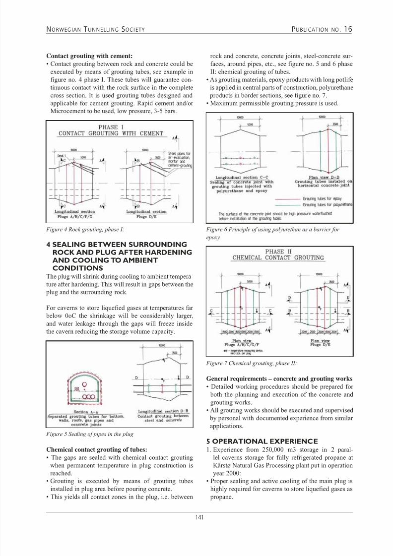
7/21/2019 Publication 16
http://slidepdf.com/reader/full/publication-16 143/181
NORWEGIAN T UNNELLING SOCIETY PUBLICATION NO . 16
141
Contact grouting with cement:• Contact grouting between rock and concrete could be
executed by means of grouting tubes, see example infigure no. 4 phase I. These tubes will guarantee con-tinuous contact with the rock surface in the complete
cross section. It is used grouting tubes designed andapplicable for cement grouting. Rapid cement and/orMicrocement to be used, low pressure, 3-5 bars.
4 SEALING BETWEEN SURROUNDINGROCK AND PLUG AFTER HARDENINGAND COOLING TO AMBIENTCONDITIONS
The plug will shrink during cooling to ambient tempera-ture after hardening. This will result in gaps between the
plug and the surrounding rock.
For caverns to store liquefied gases at temperatures far below 0oC the shrinkage will be considerably larger,and water leakage through the gaps will freeze insidethe cavern reducing the storage volume capacity.
Figure 4 Rock grouting, phase I:
Figure 5 Sealing of pipes in the plug
Chemical contact grouting of tubes:• The gaps are sealed with chemical contact grouting
when permanent temperature in plug construction isreached.
• Grouting is executed by means of grouting tubes
installed in plug area before pouring concrete.• This yields all contact zones in the plug, i.e. between
rock and concrete, concrete joints, steel-concrete sur-faces, around pipes, etc., see figure no. 5 and 6 phaseII: chemical grouting of tubes.
• As grouting materials, epoxy products with long potlifeis applied in central parts of construction, polyurethane
products in border sections, see figure no. 7.• Maximum permissible grouting pressure is used.
Figure 7 Chemical grouting, phase II:
Figure 6 Principle of using polyurethan as a barrier for
epoxy
General requirements – concrete and grouting works
• Detailed working procedures should be prepared for both the planning and execution of the concrete andgrouting works.
• All grouting works should be executed and supervised by personal with documented experience from similarapplications.
5 OPERATIONAL EXPERIENCE1. Experience from 250,000 m3 storage in 2 paral-
lel caverns storage for fully refrigerated propane atKårstø Natural Gas Processing plant put in operationyear 2000:
• Proper sealing and active cooling of the main plug is
highly required for caverns to store liquefied gases as propane.
7/21/2019 Publication 16
http://slidepdf.com/reader/full/publication-16 144/181
NORWEGIAN T UNNELLING SOCIETY PUBLICATION NO . 16
142
• To reduce required heat to freeze the outside of the plug storing liquefied gases well below 0oC – crushedrock / sand or Leca blocks should be filled outside the plug.
• Due to not proper sealing after casting of the plugs
installed in the side access tunnels to separate thecaverns for different qualities storage the leakageexperienced are too large to isolate the storages fromeach other, quality wise.
• Experience from 60000 m3 refrigerated Propanecavern no. 2 at Mongstad Refinery, using 2 stage cool-down and a concrete plug with access opening. ThePlug was cast with pipes for coolant circulation.
6 REFERENCES1. Norcem Report, Simulation of temperature and
strength development of cement from Norcem, Ny1(Standard cement), dated 08.05.2002’
2. Norcem Report, Simulation of temperature andstrength development of cement from Norcem, Ny1b(Anlegg cement), dated 08.05.2002’
3. Norcem Report, Simulation of temperature andstrength development of cement from Norcem,
4. Multiconsult & Veidekke ASA , Details from cavern plug drawings.
7/21/2019 Publication 16
http://slidepdf.com/reader/full/publication-16 145/181
NORWEGIAN T UNNELLING SOCIETY PUBLICATION NO . 16
143
10.1 CAVERNS, OPERATIONAL EXPERIENCE
Egil Ronæss
1 INTRODUCTION Numerous petroleum products are stored in caverns,some in heated caverns compared with normal ambientconditions and other under refrigerated conditions.
Products correctly stored in caverns are:• Environment friendly• Products are safely stored• At storage temperatures above 0oC stored products is
exposed to ground water • Stabile ambient conditions through the whole year.
Products stored in caverns are often for strategic stor-age, protected from land or air based attacks.
For large storage volumes (above 30 000 – 50 000 m3
storage volume) cavern storages are cheaper per m3storage volume than similar storage volume in tanks.
Large cavern storage volumes opens for favourablemarket prices by:• Seller: Sell at high price and not at the moment when
you have to sell because of full storage.• Buyer: Buy large volumes in season with low market
prices and not frequent buying due to empty storage – independent of market price.
1.1 Products Stored in Caverns
Known petroleum products stored in caverns in Norwayare:• Crude Oil, normally large caverns at atmospheric conditions.• Refinery distillation fractions and refinery complete
products:• Fuel oils• Diesel oil• Gasoline fractions• Naphtha• Condensates• Butane – slightly pressurised to avoid hydrate forming
conditions• Propane at atmospheric conditions (-42oC) or slightly
pressurised (-30 to -38o C) and pressurised (abovehydrate forming condition – above 6oC)
1.2 Operating ConditionsFor product stored at conditions below normal boiling point the atmosphere above the stored product will con-sist of a harmless inert gas saturated with vapour fromthe stored product.
For products stored at “boiling” conditions the atmos- phere above the stored product will only consist ofgaseous components from the stored product. Inert gaswill only be used in situations to avoid below design pressure conditions – to avoid air leakage into storage
1.3 Load in Facilities and other piping inside theCavernBottom Load-in pipe terminated near far end to ensurecirculation of the stored product. It is extremely impor-
tant to avoid surging in the load in line by selectingthe pipe diameter in the vertical section so large that italways will be two-phase flow (gas and load-in prod-uct). Dimension shall be based on maximum load-involume.Load in facilities for liquids, with storing temperature below boiling point, with lower explosion level (LEL)value below 6oC should only be loaded into the cavernvia the bottom load in line to avoid sparks due to staticelectricity.
Top Load-in pipe, ending in the far end. The pipe is
installed on a rack from cavern roof sparged (with holesdownwards) to ensure product distribution. Main taskTop Load in Line is for loading in warmer product thanthe one already stored to avoid roll-over.
Pressure control shaft is terminated in the cavern roof.This shaft will supply gas to maintain defined mini-mum operating pressure and release gas (to flare) whenexceeding maximum operating pressure.
Leakage Water Pump shafts (pipes) will host the leakagewater pump-out pipe.
Stored Product Export Pumps shafts (pipes) will hostthe stored product export pipes or be the export pipe.

7/21/2019 Publication 16
http://slidepdf.com/reader/full/publication-16 146/181
NORWEGIAN T UNNELLING SOCIETY PUBLICATION NO . 16
144
Chemical Injection Pipe shaft to be able to supply chem-icals preventing emulsion in the interphase betweenstored product and leakage water and for hydrate brak-ing (optional)
1.4 Pump-Out FacilitiesPumps are normally installed in dedicated caissons ina common pump pit housing leakage water pump-out pump(s) and export pumps. Leakage water pump(s)ensures via level control a ground water level to avoidground water into the product export pumps and toavoid stored product into the ground water pump(s) – through level interphase (water – hydrocarbons) meas-urement and control.
Leakage Water Pumps with drivers (el.motor or hydrau-lic) normally installed in shafts (pipe allowing the pumpinstallation inside). The installation shafts in pumpsump, well into the water phase. Normal is 2 pumps (1spare). Automatic Start / Stop based on given interfacelevels between water and stored product. Leakage water pumps capacity must exceed the normal leakage volumewith a large margin to cover for max leakage water vol-umes possible.
Stored Product Export Pumps with drivers (el.motoror hydraulic) installed in shafts / caissons (pipe allow-ing the pump installation and removal from the caverntop). The shafts in pump sump, ends well above thewater phase. Number of pumps: minimum2 pumps and
required number of pumps shall meet the maximumload out volume. Due to allowed installation level below the cavern floor due to the pump pit almost thefull cavern storage volume is active. Export pumps must be designed for all actual operating conditions like thecavern pressure and product levels. Mini-flow systemis required.
Submerged pumps installed in casings from surface arethe normal way.
1.5 Instrumentation
Instrumentation related to Storage Caverns is normallyrelated to level, pressure, temperature and flow.
Level Measurements will be for monitoring:• Interphase level between Water and product (to avoid
water exported with the stored product and stored product pumped out with the leakage water.)
• Level of stored product (interphase between productand gas phase) to give operating information on storedvolume – to give information on volumes available forexport or import.
Flow measurements are installed above ground for
monitoring:• Correct export volumes.
• Pumps mini-flow control.
Pressure measurements are installed above ground andwill be for monitoring of:• Pressure control inside the cavern – (releases to flare
(or safe location))• Operating pressure above the stored product, (avoid-ing pressure above design pressure and for pressure below approved operating pressure to avoid air intothe storage)
• Monitor export pressure (and temperature) of stored“boiling” products.
Caverns operating with variable pressure from pres-sures below to pressures well above normal operating pressures (storage with variable pressure gas pillow)will require vacuum and overpressure valves (protec-tion) setting the operating pressure limitations. Thisoperating philosophy results in minimum requirementto flare off gas volumes from the storage as well as useof required inert gas to maintain the requireds operatingconditions.
Temperature measurements will be for monitoring of:• Cavern rock temperature.• Stored product temperatures at different levels in the
cavern (roll-over prevention and for certain productalso monitoring operating temperatures to be wellabove hydrate formation).
1.6 Leakage waterPre-injection into the rock massive prior to start up of blasting to ensure acceptable ground water leakage intothe cavern is the basis for successful operation. Groundwater inflow will vary with ground water level and cav-ern operating pressure.
Ground water leakage into the cavern requires collectionand pump-out facilities to avoid ground water in-mixinginto stored product. Ground water is normally collectedin the pump pit and removed by ground water pumps.Leakage water pump capacity must by far exceed the
leakage water inflow.
The contact between ground water and stored productsmust avoid emulsifying conditions.
The contact between ground water and stored productswill bring impurities into the ground water and alsosmall droplets of stored product.
Leakage water cleaning of pumped out ground water isa requirement to maintain acceptable environment.
2 TESTING WHEN STILL ACCESS
Ground Water leakage incl. test of ground water pumpcapacity is important to test prior to sealing off access

7/21/2019 Publication 16
http://slidepdf.com/reader/full/publication-16 147/181
NORWEGIAN T UNNELLING SOCIETY PUBLICATION NO . 16
145
and possibilities to modify. In cases with leakage wateringress larger than leakage water pump acceptable oper-ation, it may be necessary to perform injection sealingof water channels. Leakage water inflow will vary with pressure inside the cavern and the ground water level
– varying with precipitation conditions.
Perform tests of installed instruments and qualifica-tion of measurement accuracy. All instruments with noaccess after put in operation must have the final tests(example: surrounding wall temperature measurements,water level in pump pit).
Test installation and withdrawal of export pumps arehighly recommended.
2.1 Cool Down for Caverns operating well below 0oC– Two (2) stage cool-down, Stage 1 - Air Cooling Stage.Refrigerated caverns may be cooled down in 2 princi- pally different methods:1. One-stage cool-down using the stored product’s heat
of evaporation as coolant using nozzles to createsmall liquid droplets to give efficient evaporation.
2. Two-stage cool-down:• First stage using circulating cooled air • Second stage using product to be stored and similar
principle as for one-stage cool-down.
The two-stage cool-down - stage one – normally usescirculating air inside the cavern. The circulating air is
normally cooled using brine circulated from a conven-ient location on ground level. The circulating brine iscooled by a refrigeration cycle. The air coolers requirede-riming in intervals to maintain average heat transferefficiency.
The air-cooling MUST also include active main plugcooling.
3 COMMISSIONINGCommissioning is normally defined as testing andcontrol of all vital functions prior to introduction of the
product to be stored. Many of the commissioning activi-ties take place after the main plug has been sealed off.
Some tests may be completed after the product has beenintroduced into the cavern.
Level measurement of the water level may be com- pleted. Control of product level measurement at levels below normal operating levels may be checked againstthe ground water level measurement. Finalisation of product level measurement will be performed duringintroduction of product into the cavern.
Pump pit water level control / pump-out start and stopof pump as function of level.
Pressure and leak testing is normally related to sealtightness of the main plug and riser shaft(s) at design pressure conditions (ground water pressure surroundingthe cavern shall at all cavern rock surfaces be higherthan pressure experienced inside the cavern).
Oxygen must be removed by inert gas prior to introduc-tion of hydrocarbons to avoid any danger for explosioninside the cavern and in the pressure control / flaresystem outside the cavern. Nitrogen (N2) -normallyor CO2 are used for inertising the cavern. Inertising isunderstood as bringing the oxygen content in the cavernto an acceptable level:• The inertising of an air filled cavern depends on the
possibility to avoid intensive mixing of the inert gasand the air inside the cavern. Required inert gas vol-ume varies between 3 and 4 times the cavern volume.Distance between inert gas inlet and gas outlet fromthe cavern, through pressure control route is vital tominimise the required inert gas volume.
• The inertising may be performed during the leak testand using the cavern 80 to 90 % water filled to reducethe volume of inert gas required to establish acceptableoxygen level in the cavern, and then by water pump-out replace water with inert gas. (This will be basedon cost of water + cost for water pump-out againstreduced cost of inert gas.)
Purging is understood as change-out of inert gas withvapours of stored product and is only fully relevant for
products stored at boiling condition (vapour pressureequals storage pressure).
Installation of export pumps.
3.1 Caverns Operating at ambient or higher tem-peratures No special commissioning activities in addition to theactivities already described.
3.2 Commissioning including Cool Down for Cavernsoperating well below 0oC
Air must be removed by inert gas prior to introduction ofhydrocarbons to avoid any danger for explosion. Prior tointroduction of liquid hydrocarbons into the cavern forcool-down purposes the atmosphere must be changed tostored product vapour. To avoid local temperatures far below stored product temperature.
During the early phase of the cool-down process leak-age water inflow will continue even after average walltemperature is below 0oC, partly due to the water flowand calorific value required to freeze water.
During cool-down water ending in the pump pit must
be removed to ensure a free board between frozen waterlevel and product export pump suction level. Pump-abil-

7/21/2019 Publication 16
http://slidepdf.com/reader/full/publication-16 148/181

7/21/2019 Publication 16
http://slidepdf.com/reader/full/publication-16 149/181
NORWEGIAN T UNNELLING SOCIETY PUBLICATION NO . 16
147
- All supply of product requires water pump-out – preferably to buffer storage (to reduce water flowto effluent treatment.
- All pump-out of product are replaced with water. - Ground water level control by total level above cav-
ern roof top.
4.2 Caverns operating above 0oC and hydrate for-mation conditionsProducts stored at temperature above hydrate forma-tion conditions at product boiling point at temperatures below ambient temperature leading to product boil-off.
Boil-off can be recovered by compression, condensationand re-injection into the cavern or used as fuel to firedenergy consumers.
This storage method is applied for:• Propane at the Rafnes Noretyl Ethylene Cracker, start-
up year 1977.• Butanes at Mongstad refinery, Vestprosess Project
(start-up year 2000)
4.3 Caverns operating well below 0oCDuring cool down some of the leakage water will freezeand create an ice layer on the rock surface. From this icelayer some ice will sublimate into the caverns atmos- phere. If the cavern has vapour recovery facilities withrecycling of recovered product to the cavern the recov-ered product must be dried prior to cool-down.
During the cool-down process inflow of leakage waterstops due to sub-zero conditions in the surrounding rockmassive. This seals the surrounding rock.
Products stored at temperatures near normal boiling point (1 atmosphere abs.) at temperatures far belowambient temperature leading to product boil-off.
Boil-off can be recovered by compression, condensationand re-injection into the cavern or used as fuel to firedenergy consumers.
This method is applied for Propane storage at:• Kårstø natural gas and condensate processing plant,
start up year 2000 – 1 stage cool down. Problems withwater leakage between concrete plug and surroundingrock. This leakage lasted until long after “completed”cool down. Reason:
- Main plug cool-down due to inadequate coolingintensity of the plug region.
- Lack of adequate sealing injection between concrete plug and surrounding rock.
• Mongstad refinery: - Cavern no. 1 put in operation year 2000. Reduced
storage capacity due to frozen ground water intrusionduring cool down – 1-stage cool down.
- Cavern no. 2 put in operation year 2003 – 2 stagecool down. Full storage capacity maintained.
5 OPERATIONLoad in from adjacent production facilities for export or
from unloading ships for storage and distribution:• Load in from production - relatively small load inflows and high export flows
• Load in from unloading ships – high load i9n rates andsmaller export rates.
Pressure control depends on operating philosophy as basis for mode of operation, see chapter 4.1.• Minimising use of seal gas and vapour release to flare
/ atmosphere (minimise component losses).• Constant vapour / gas pressure above stored product
– gas flow in and out depend on product level changesin the cavern.
• Vapour / boil-off gas recovery when products arestored at boiling conditions.
• Caverns operating with variable operating pressurerequires very low consumption of inert gas and releas-es to atmosphere / flare.
5.1 Caverns Operating at ambient or higher tem-peraturesGround water level control must be working in pump pitto avoid in-mix of water into stored product and stored product into leakage water pump-out.
Modes of operation for pressure and inventory control,see chapter 4.1.
Leakage water pumped out from the cavern containsdissolved and occasionally also a water - hydrocarbonemulsion. This pump-out requires a cleaning (nor-mally a biological cleaning process) prior to release asapproved effluent from the storage facilities
5.2 Caverns operating well below 0oCRoll-over prevention:• Only fully refrigerated product to be loaded into the
cavern bottom load-in line.• Not fully refrigerated product should be loaded intothe cavern via a roof suspended line with limited sizedrain holes (sparged) to allow the product cool downto storage condition by a flash.
To maintain stable product storage temperatures:• Fully refrigerated product load-in vie bottom load-in line.• Maintain stable storage pressure.
Vapour recovery facilities and optional drying facili-ties must be in operation to avoid operating problems.Operating problems created by ice / hydrate formation
can be removed by methanol injection just upstream the problem points.

7/21/2019 Publication 16
http://slidepdf.com/reader/full/publication-16 150/181
NORWEGIAN T UNNELLING SOCIETY PUBLICATION NO . 16
148
YOUR partner in
Underground
Technology
For more information;contact Eivind Grøv;[email protected]
• Laboratory Testing
• In-situ Rock Stress
iiiMeasurements
• Rock Mechanics
• Engineering Geology
• Numerical Modelling
• Health, Environment
iiiand Safety Aspects
• Construction Method
iiiEvaluation• Value Engineering &
Independent Reviews

7/21/2019 Publication 16
http://slidepdf.com/reader/full/publication-16 151/181

7/21/2019 Publication 16
http://slidepdf.com/reader/full/publication-16 152/181
NORWEGIAN T UNNELLING SOCIETY PUBLICATION NO . 16
150

7/21/2019 Publication 16
http://slidepdf.com/reader/full/publication-16 153/181
NORWEGIAN T UNNELLING SOCIETY PUBLICATION NO . 16
151
1 INTRODUCTIONFor use of bringing Pipelines onshore or offshore underrough conditions and rocky shore approaches.
The shore approach tunnels are normally sea waterfilled, resulting in problem free operation.
2 SHORE APPROACH TUNNELSConcrete landfall tunnels was used for the Statpipe inand outgoing pipelines put in operation 1985 and stillin operation. The landfall site experiences very roughconditions. There have been some structural problemsduring the period in operation, these have been success-fully repaired.
Blasted tunnels from onshore rocky landscape to select-
ed rocky structures offshore.
Sleipner Condensate pipeline project landfall rock blasted tunnel put on-stream 1993 at Kalstø on Karmøyisland was a successful project. The tunnel was con-structed with a short side tunnel branch for problemfree construction of an optional side tunnel. This tunnelaccess start has been used for the “Åsgard Transport” pipeline project a 42” diameter pipeline put in operationyear 2000.
3 FJORD CROSSING TUNNELS
Sub-sea tunnels to avoid any interference with shiptraffic and ships anchoring, as well as possible difficult pipe-laying.
“Dry” tunnels allows frequent visual inspections forfollow-up. The “Dry mode” requires water pump-outfacilities at low points.
Rafnes to Herøya tunnel put on-stream 1977 for trans-fer of Chlorine, Vinyl-chloride and liquid mixture ofEthane, Propane / Propylene containing Butane as fueland feedstock for the Ammonia plant N-II. This has been a water filled tunnel and has been successfully
in operation since start-up. Modifications and eventualrepairs will require pump-out for access.
Statpipe put on-stream 1985 has a concrete cast landfalltunnel at Kalstø, West side of Karmøy island. BetweenKarmøy landfall and Kårstø Gas Processing facilitiesthere are 3 fjords where the Statpipe incoming “RichGas” pipeline, the outgoing “Sales Gas” pipeline andsignal and communication cables are routed through 3sub-sea fjord crossing tunnels. The tunnels have been“dry” – leakage water has been pumped out to sea viadrain pipe from pump house site onshore. From 1993the fjord crossing tunnels also hosted the SleipnerCondensate pipeline, for un-stabilised condensate, toKårstø for processing to commercial products. Theoperational experience is very good.
10.3 SHORE APPROACH TUNNELS and FJORD CROSSING
TUNNELS, OPERATIONAL EXPERIENCEEgil Ronæss

7/21/2019 Publication 16
http://slidepdf.com/reader/full/publication-16 154/181
NORWEGIAN T UNNELLING SOCIETY PUBLICATION NO . 16
152

7/21/2019 Publication 16
http://slidepdf.com/reader/full/publication-16 155/181
NORWEGIAN T UNNELLING SOCIETY PUBLICATION NO . 16
153
ABSTRACT: After the Second World War the Norwegian Authorities started considering a safe storage system for fuel in the Oslo area. The rock mass in the Ekeberg hill inSouthern Oslo was of good quality, and close to theexisting oil terminal at Sjursøya. The storage facilities
built in rock caverns under the Ekeberg hill are still after 37 years of operation one of the main oil storage facilities for refined oil products in Norway. The expe- rience after all these years of operation is remarkable.Only a few stops in operations and no major accidents
confirm the efficiency and safety of the facilities.
INTRODUCTIONThe main oil storage facility for refined products in Norway is located in rock under the Ekeberg hill in
10.4 EKEBERG PETROLEUM STORAGE FACILITY
EXPERIENCE FROM THE EKEBERG OIL STORAGE ANDEKEBERG TANK
Asbjørn Føsker
Figure 1: Aerial photo of Sjursøya Oil Terminal and the Ekeberg hill where the Ekeberg Oil Storage and the Ekeberg Tank are
located (Photo: Fjellanger Widerøe AS, 2003)
Southern Oslo in the harbour area. This storage facilitywas built in rock caverns of good quality close to theexisting oil terminal at Sjursøya.
The facilities are used for temporary storage by the fivelargest oil companies operating in Norway, and for stra-tegic oil storage by the Norwegian Government. Eachoil company has separate storage chambers for differentqualities of gasoline, diesel and kerosene.
In comparison with similar storage facilities around theworld, the installations in the Ekeberg hill are huge. In1995, approximately 50% of the total annual demandfor petroleum products in Norway passes through thecaverns.
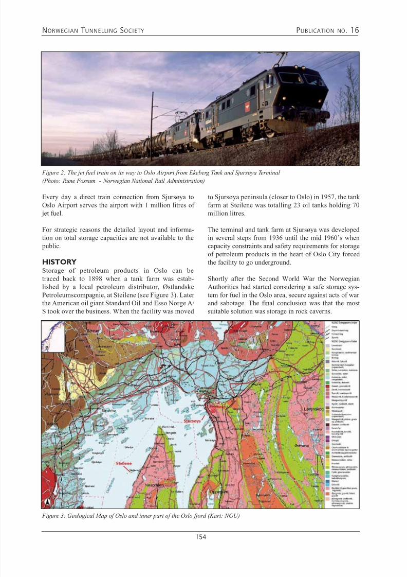
7/21/2019 Publication 16
http://slidepdf.com/reader/full/publication-16 156/181
NORWEGIAN T UNNELLING SOCIETY PUBLICATION NO . 16
154
Every day a direct train connection from Sjursøya toOslo Airport serves the airport with 1 million litres of jet fuel.
For strategic reasons the detailed layout and informa-tion on total storage capacities are not available to the public. HISTORYStorage of petroleum products in Oslo can betraced back to 1898 when a tank farm was estab-lished by a local petroleum distributor, ØstlandskePetroleumscompagnie, at Steilene (see Figure 3). Later
the American oil giant Standard Oil and Esso Norge A/S took over the business. When the facility was moved
Figure 2: The jet fuel train on its way to Oslo Airport from Ekeberg Tank and Sjursøya Terminal
(Photo: Rune Fossum - Norwegian National Rail Administration)
to Sjursøya peninsula (closer to Oslo) in 1957, the tankfarm at Steilene was totalling 23 oil tanks holding 70million litres.
The terminal and tank farm at Sjursøya was developedin several steps from 1936 until the mid 1960’s whencapacity constraints and safety requirements for storageof petroleum products in the heart of Oslo City forcedthe facility to go underground.
Shortly after the Second World War the NorwegianAuthorities had started considering a safe storage sys-tem for fuel in the Oslo area, secure against acts of war
and sabotage. The final conclusion was that the mostsuitable solution was storage in rock caverns.
Figure 3: Geological Map of Oslo and inner part of the Oslo fjord (Kart: NGU)
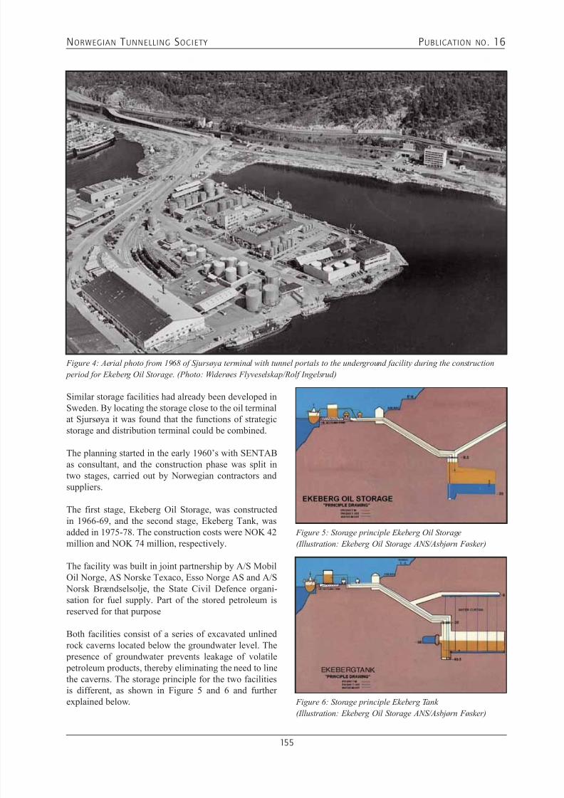
7/21/2019 Publication 16
http://slidepdf.com/reader/full/publication-16 157/181
NORWEGIAN T UNNELLING SOCIETY PUBLICATION NO . 16
155
Similar storage facilities had already been developed inSweden. By locating the storage close to the oil terminal
at Sjursøya it was found that the functions of strategicstorage and distribution terminal could be combined.
The planning started in the early 1960’s with SENTABas consultant, and the construction phase was split intwo stages, carried out by Norwegian contractors andsuppliers. The first stage, Ekeberg Oil Storage, was constructedin 1966-69, and the second stage, Ekeberg Tank, wasadded in 1975-78. The construction costs were NOK 42million and NOK 74 million, respectively.
The facility was built in joint partnership by A/S MobilOil Norge, AS Norske Texaco, Esso Norge AS and A/S Norsk Brændselsolje, the State Civil Defence organi-sation for fuel supply. Part of the stored petroleum isreserved for that purpose
Both facilities consist of a series of excavated unlinedrock caverns located below the groundwater level. The presence of groundwater prevents leakage of volatile petroleum products, thereby eliminating the need to linethe caverns. The storage principle for the two facilitiesis different, as shown in Figure 5 and 6 and further
explained below.
Figure 4: Aerial photo from 1968 of Sjursøya terminal with tunnel portals to the underground facility during the construction
period for Ekeberg Oil Storage. (Photo: Widerøes Flyveselskap/Rolf Ingelsrud)
Figure 6: Storage principle Ekeberg Tank
(Illustration: Ekeberg Oil Storage ANS/Asbjørn Føsker)
Figure 5: Storage principle Ekeberg Oil Storage
(Illustration: Ekeberg Oil Storage ANS/Asbjørn Føsker)

7/21/2019 Publication 16
http://slidepdf.com/reader/full/publication-16 158/181
NORWEGIAN T UNNELLING SOCIETY PUBLICATION NO . 16
156
STORAGE SYSTEM ANDGROUNDWATER CONTROLIn Ekeberg Oil Storage the top level of the stored oil product is constant while a water bed in each cavern isconstantly adjusted. Petroleum is stored with 10 meters
hydrostatic under-pressure relative to sea. The productsfloat on a bed of sea water, which is pumped in or outfrom the fjord as the amount of oil varies, thereby main-taining the under-pressure.
The caverns are always filled to the top, with only asmall petroleum surface area exposed to air. The top ofthe caverns is formed as a bottleneck with a constantcross-section to minimize the surface level of the oil andreduce the evaporation loss. When receiving oil products, water is pumped out fromthe bottom of the cavern to avoid oil pollution in thefjord. As a safety measure this water passes through anoil separator before being discharged into the sea.
Figure 7: Storage cavern at Ekeberg oil storage. The import
pipeline is coming in at the top, the product pumps are hang-
ing at the top. The water pipeline goes all the way down to
the bottom. The picture is taken during construction, before
the cavern was filled with water and gasoline.
(Photo: Ekeberg Oil Storage ANS)
In Ekeberg Tank the volume of the waterbed is constantwhile the surface level of the stored oil product rises andfalls depending on the stored quantities. Use of this prin-ciple is possible because Ekeberg Tank is used to storeaviation fuel and gas-oils which are far less volatile than
automotive gasoline. The caverns are located well below the sea and ground-water levels with the deepest caverns extending down toabout Elev. -45 m.
Extensive control measures have been implementedto ensure that the groundwater is always at a suffi-cient level. A water curtain consisting of drilled holesconnected to an open canal in a rock tunnel has beeninstalled to avoid any interconnection between thecaverns of Ekeberg Oil Storage and the lower elevatedEkeberg Tank.
Groundwater leaking into the caverns of Ekeberg Tankis collected and pumped to the harbour basin through anoil separator.
ROCK CONDITIONSThe rock consists of massive Precambrian gneisses ofgood quality. Blasting operations and excavation of tun-nels and caverns were carried out without major techni-cal problems.Limited rock support was needed and the rock massstability is maintained by bolts and shotcrete only. None
of the facilities required concrete lining.
Over the 37 years of experience only one small piece ofrock has been recorded falling from the roof in one ofthe caverns. Rock mass stability problems have not beenobserved in any other part of the facility.
TECHNICAL INSTALLATIONSPipelines have been installed in rock tunnels with easyaccess and adequate space for maintenance. In totalthere are 4 km of walkways and 35 km of pipes trans- porting petroleum products within the facility.
All operations are highly automated. The control centreis located underground, from where the entire facility isoperated and controlled, and is manned continuously.
High-voltage electricity is supplied to transformers placed in rock. Separate large diesel aggregates cansupply sufficient electricity in case of breakdown of theexternal supply. EXPERIENCES FROM OPERATIONThe first receipt of petroleum was on April 29, 1970. Nodifficulties were experienced that day and over the next
37 years, there has hardly been any stop in the opera-tions and no major accidents.

7/21/2019 Publication 16
http://slidepdf.com/reader/full/publication-16 159/181
NORWEGIAN T UNNELLING SOCIETY PUBLICATION NO . 16
157
The storage complex requires few people during opera-tion, and the operating costs are very low.
These operational experiences confirm the efficiencyand safety of the facilities. This is remarkable as tankers
arrive almost every day, pending between 260 to 350ships per year, and products are pumped out from thecaverns continuously.
Corrosion in pipes and pumps has caused some prob-lems. This has been experienced in product pipes as wellas in sea water pipes. However this has been overcome by replacing equipment as required.
The equipment is to a large extent similar to that inships. The Ekeberg Petroleum Storage Facility is a lotolder than the normal life duration of ships. At the timeof original design, experience with such facilities waslimited. Hence equipment of less than the best qualitywas chosen for economical reasons, which over the longrun has proved not to have been an optimum choice.However, the facility has served its owner’s well forover almost four decades.
Delegations from many parts of the world have visitedthe facility.
REFERENCES1. Føsker, A. (February 2007): “Experience from the
Ekeberg Petroleum Storage Facility”, Letter to NFF,
1 page
2. Føsker, A. (1995) Paper for the NFF Publication No.10: Ekeberg Oil Storage and Ekebergtank - CentralOil Storage Facilities for Norway, Paper No. 9, 3 pages
3. Ivarson, H, (2002): “Ekeberg Oljelager / EkebergTank: Der 5.000 kubikk anses som en «skvett»”,Article in Logistikk & Ledelse, No. 10 - 2002 (in Norwegian)

7/21/2019 Publication 16
http://slidepdf.com/reader/full/publication-16 160/181
NORWEGIAN T UNNELLING SOCIETY PUBLICATION NO . 16
158

7/21/2019 Publication 16
http://slidepdf.com/reader/full/publication-16 161/181

7/21/2019 Publication 16
http://slidepdf.com/reader/full/publication-16 162/181
NORWEGIAN T UNNELLING SOCIETY PUBLICATION NO . 16
160
Storage CapacityThe concept of underground storage in rock caverns has proved efficient and has enabled the steady extensionof the facility. Statoil Mongstad had 27 rock cavernsfor storage of hydrocarbons in operation in December
2005.Storage cavern number 28 - the New Naphtha Cavern(NNC) was then under construction with expected com- pletion date in November 2006.
Requirements for Hydrocarbon Storage in RockCavernsThe basis for safe and good operation resides in:• Public rules and regulations• Process conditions• Operation and maintenance programme• Appropriate choice of equipment• Allowing equipment to operate as intended (as believed
or known to operate if one has experience)• Awareness of what can be done and where in the
expected service life of the storage cavern• Choice of simple, solid and robust solutions• Choice of technical solutions that allow future meas-
ures to deal with corrosion and to upgrade the plant.
Input during Conceptual Design Phase to Con-struction Phase• The people who operate and maintain rock cavern stor-
ages have a wealth of experience. But will those whodesign and construct the caverns take their experience
into account?• It is during the design phase and early in the construc-tion phase that the principles are developed and thestrategic choices made, thus creating the conditions foroperation and maintenance.
• The planning and construction time of a storage cavernis from 2 to 3 years. The operation and maintenance period is from 0 to 100 years. Do we give this suf-ficient consideration?
• Experience has shown that early in the projects weshift our attention from general principles and instead become embroiled in details which may often be dif-ficult to abandon even if it is later found that they wereill-advised.
REFERENCES1. Ulvøy, J. (December 2005): “Erfaringer fra Mongstad”,Statoil Presentation at the Rock Cavern Storage Seminarat Norconsult, 7 pages (in Norwegian)
Figure 3: Operational flow chart for the detail design phase - New Naphtha Cavern Arena (Illustration: Statoil)
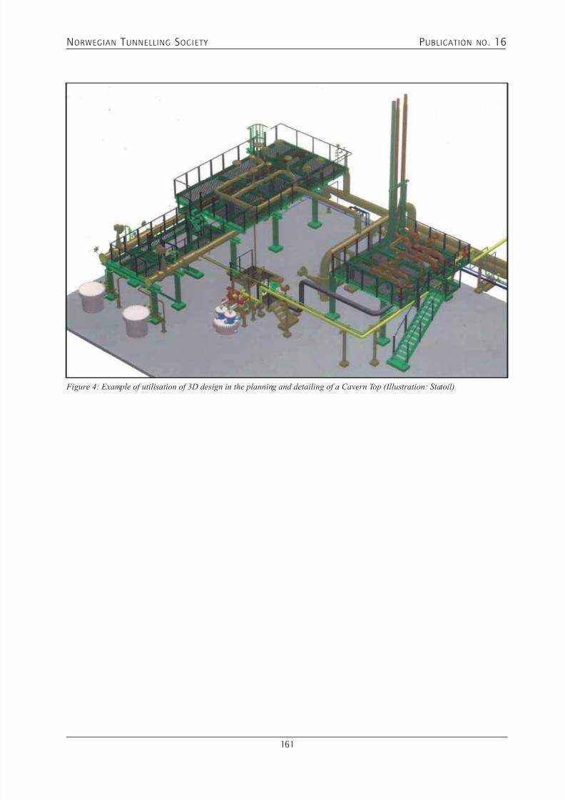
7/21/2019 Publication 16
http://slidepdf.com/reader/full/publication-16 163/181
NORWEGIAN T UNNELLING SOCIETY PUBLICATION NO . 16
161
Figure 4: Example of utilisation of 3D design in the planning and detailing of a Cavern Top (Illustration: Statoil)

7/21/2019 Publication 16
http://slidepdf.com/reader/full/publication-16 164/181

7/21/2019 Publication 16
http://slidepdf.com/reader/full/publication-16 165/181
NORWEGIAN T UNNELLING SOCIETY PUBLICATION NO . 16
163
11. SUBSEA TUNNELLING FOR OIL AND GAS
- CONCEPT STUDIESArnulf M. Hansen
Jan K.G. Rohde
INTRODUCTIONThe Norwegian oil company, Statoil has through theyears placed considerable efforts into finding the bestsuitable solutions to facilities and equipment in order to bring oil and gas from the reservoirs to the markets.
In the late 70-ies, beginning of the 80-ties the petro-leum activity on the Norwegian Continental Shelf wasextended to greater depths and exposed to more extremeenvironmental conditions, and consequentially leadingto larger and more complex installations.
The need for alternative field development solutionsincreased and Statoil was considering tunnels as part ofa field development as one alternative. Several conceptsof application of field tunnels were studied:
• Platforms plus placing pipeline(s) in a tunnel to trans- port hydrocarbons from the oil field to shore terminalsand thus overcome complex shore approach, as well.
• Connecting of a sub sea wellhead template to tunnel based equipment for processing and transportation toshore based facilities.
• Placing and operating all equipment for drilling, processing and transportation to shore in a tunnelsystem
The Troll field was used as an example for the study.
The Field Tunnel concept assumed a number of techni-cal solutions which would demand extensive develop-ment of new technology.
In February 1984 Statoil entered into an agreementwith a group of consulting engineers for a pre-feasi- bility study on a field tunnel concept. The group con-sisted of Ødegård & Grøner A/S (head of the group),A/S Geoteam, Jernbeton A/S, Resconsult A/S, A/SGaute Flatheim, Department of Geology, Departmentof Mining Engineering and Department of ConstructionEngineering at NTH –University of Trondheim. Block31 East at The Troll field was chosen for an investiga-
tion of a possible field tunnel system from Fedje Islandto the oil field.
In the autumn of 1984 two separate joint ventures between contractors and consulting engineers wereawarded contracts by Statoil for a feasibility study ontunneling to the Troll Field some 55km ashore.
THE PETROMINE CONCEPTIn 1978 two Norwegian consulting engineers and acontractor started to explore the feasibility of an oilmine concept on the Norwegian continental shelf. In November 1984 two of the companies that startedthe oil mine studies in 1978, Ing. A.B.Berdal A/S andcontractor Ing. Thor Furuholmen A/S founded ThePetromine Company. In the end of 1985 the companywas reorganized with additional partners, NorwegianRig Consultants a/s and Norcem Cement A/S. ThePetromine Company continued with the second phase of
the study for Statoil as well as its own R&D work.

7/21/2019 Publication 16
http://slidepdf.com/reader/full/publication-16 166/181
NORWEGIAN T UNNELLING SOCIETY PUBLICATION NO . 16
164
“TROLL I FJELL”The other joint venture, The HAG Group consisted ofcontractor Astrup Høyer A/S and consulting engineerGrøner A/S. They named their concept study “Troll iFjell” (Troll in Rock). The basic concept of the HAG
Group was similar to the Petromine concept.
TASK OF THE GROUPSThe task of the groups was to investigate:•-geology along the tunnel alignment from shore to the
oil field• construction technology of a tunnel system to the oil
field• oil production drilling from underground chambers
• oil processing underground at the oil field• transport of the hydrocarbons from the field to shore based facilities
• safety and• economical aspects of the concept
DESCRIPTION OF CONCEPTThe tunnel concept comprises a network of tunnelscontaining and connecting the required equipment fordrilling, processing and transportation to a shore basedterminal.The main tunnel system consists of three parallel tun-nels excavated upward from a Base Station near the
shore towards the oil field. At 8-10km intervals thethree tunnels are interconnected enabling divided sec-
tion to be established. From the main tunnel systemtwo parallel tunnels to each drainage area at the fieldwould be constructed. These tunnels are connected withtransverse tunnels where the oil drilling equipment anda major part of the processing equipment are located
inside pressure tight locks.The three main tunnels are reserved for transport ofhydrocarbon in pipes, transport of equipment and per-sonnel, support facilities, ventilation etc. From the BaseStation four tunnels lead to surface where the shoreterminal is located.
GEOLOGYThe geology along the oil field tunnels has a great vari-ety from precambrian crystalline rocks to young andsoft sedimentary rock formations, partly influenced bytectonical features, faults and fracture zones.
In brief the crystalline bedrock consists of varioustypes of granites, gneiss and schists while the youngersedimentary rock formations are layers of limestones,sandstones, shales and mudstones of various quality.The sedimentary rock formations are mainly from thecretaceous, paelocene and eocene periods. The subsea
rock formations are covered by tertiary and quarternarysediments.
Geology of Norway and the Continental Shelf

7/21/2019 Publication 16
http://slidepdf.com/reader/full/publication-16 167/181
NORWEGIAN T UNNELLING SOCIETY PUBLICATION NO . 16
165
From more than 30 subsea strait crossings and severalshore approaches in Norway, excavation methods andtechniques are developed to cover the challenges expect-ed for subsea tunnelling in the crystalline formations.
Tunnelling deep below sea level through soft sedimen-tary rock formation includes several challenges likehigh rock stresses, squeezing rock, structure collapsewith water inflow at high pressure, flowing groundwith sand and mudflow, gas pockets, mainly methanewith high explosive risk. Studies were made to developmethods to detect soft structures and gas pockets aheadof the tunnel face.
CONSTRUCTION OF TUNNELSThe success of a field tunnel concept will highly dependupon the construction rate of the tunnels. In order toachieve a sufficient high rate of tunneling, use of TBMs(tunnel boring machines) was considered to be a must.
Open Hard Rock TBMs and Single Shielded TBMswould be used for boring of the tunnels in the precam- brian rocks (Gneiss, Granite) the first kilometers fromthe shore, and in the sedimentary rocks (Sandstones)respectively. The TBM would be equipped with rockdrills for probing ahead of the cutterhead. Cement andor chemicals would be injected as required to protect thetunnels from leakage. Another important purpose of the probing is to get a pre-warning of shallow gas. Shouldgas be found, the rock would be injected with chemicalsto lower its permeability and gas would be drained fromthe tunnel heading.
A major challenging factor for the feasibility of thefield tunnel concept was the tunnel logistics. HighTBM advance rates would consequently require largetransport capacity of tunnel muck, materials and con-crete segments for lining of tunnel and other support
measures.
TUNNEL CONSTRUCTION DATADistance from ashore: 55kmTotal length of tunnels to be bored: 240kmInside diameter of tunnel: 5m (after lining)Depth below sea level at production area: 600mDepth below sea level at base station: 700m Number of tunnel boring machines: 8Volume of bored rock (In-Situ): 6 Million cubic metersConcrete lining: 1 Million cubic metersDesign load on lining: 10-11 MPaBack fill: 200,000 cubic metersProbe drilling, minimum: 800kmConstruction time: 8 years
ADVANTAGES OF FIELD TUNNELSCompared with fixed production platforms, the fieldtunnel concept offers the following advantages:Low operating and maintenance costs Not affected by weather conditionsSafer both for the personnel and for the environment National security - Low sabotage risk – Protection fromwar actionsReliability – low corrosion risk
Protecting a vulnerable environment from uncontrolled blow-outs No conflict of interest with the fishing industry No hazards to ship navigation
CONCLUSIONSIn 1985 after the concept studies, Statoil drew the con-clusion that it is possible to construct tunnels from shoreunderneath the sea bed as far as 50-60 km in rocks ofqualities equivalent to the Troll area and that it is pos-sible to install and operate equipment for processingand transportation of hydrocarbons in the tunnel system.
7/21/2019 Publication 16
http://slidepdf.com/reader/full/publication-16 168/181
NORWEGIAN T UNNELLING SOCIETY PUBLICATION NO . 16
166
To enable drilling of production wells from the tunnelswould require extensive technology development ofdrilling equipment and procedures.The concept including drilling of production wells fromthe tunnels was showing the most promising economical
potential. Further, the concept is most suited for fieldsclose to shore and for fields in deep and hostile waters.
FURTHER DEVELOPMENTBeside methods and equipment for drilling and operat-ing production wells in tunnel, Statoil listed the follow-ing topics for further development:- TBMs for high advance rates and able to cope with
high ground pressure in sedimentary rocks at greatdepths.
- Effective and reliable mapping of geology and moni-toring of water and gas under high pressure ahead ofthe tunnel face.
- Grouting for stabilizing of rock and leakage preventionagainst water and gas under high pressure.
POSSIBILITIES FOR THE FUTUREStatoil had through the concept studies established thefeasibility of the major elements involved and identi-fied the areas which would need further technologydevelopment in the future. They were of the opinionthat the field tunnel concept was showing such promis-ing economic and technical potential that it should befurther developed.
In the mid 80-ies similar concept studies as for the Trollfield were, as well, made for the “Haltenbanken” oilreservoir, 40-50km from shore west of Mid Norway.Today these oil fields are operated by conventional plat-forms and sea bottom equipment.
Further north, outside the coast of Northern Norway andin the Barents Region where oil fields are closer to thecoast line and the weather condition are extreme dur-ing winter time, field tunnels could be an alternative toconsider again in the years to come.
REFERENCES:1. M.K. Dørheim and Ottar Rekdal, Statoil (1985):“Tunnels for developing offshore fields”
2. Ødegård & Grøner A/S (1984): Feasibility studyreport – “Tunnels to the Continental Shelf”
3. K/S Petromine A.S (1987): “The Petromine Concept – An Introduction to the Oil Mine Concept of Norway”
4. HAG Group (1985): Feasibility study report – “Trolli Fjell”
5. A.M. Hansen’s notes from: Mr. John Gerhardsenof Statoil’s presentation of the Troll Field TunnelConcept at NIF seminar, Oslo, December 4, 1985

7/21/2019 Publication 16
http://slidepdf.com/reader/full/publication-16 169/181
NORWEGIAN T UNNELLING SOCIETY PUBLICATION NO . 16
167
ACKNOWLEDGEMENTS
Publication No. 16 from the Norwegian Tunnelling Society NFF, a presentation of Norwegian concepts utilizing theunderground for the Norwegian oil and gas industry is prepared by NFF members, all professionals with in-depththeoretical expertise and wide practical experience from domestic and international assignments.
EDITORIAL COMMITTEE
HANSEN, Arnulf MM.Sc. Mining Engineering. Professional career started with copper mining in Sulitjelma, introducing the firstRobbins Raisedrill and TBM ever in Norway. Employed by MCS and Atlas Copco representing Robbins equipmentin Scandinavia, then working in the construction sector through Statkraft Anlegg and NCC. Mr. Hansen has preparednumerous papers mainly on mechanical excavation of rocks. He is now head of AMH Consult AS.Address: Kastanjev. 14E, NO-3022 DRAMMEN, Norway.Tel.: +47.32 82 12 00 / +47.901 69 726, e-mail: [email protected]
NEBY, ArildM.Sc. Engineering Geology, Senior Engineering Geologist, Director of the Board NFF and member of theInternational committee. Mr. Neby is a senior adviser with long time experience as consultant within geologicalengineering, rock engineering and rock mechanics. Field mapping, planning, design, supervision, main activitywithin design and construction follow up of underground structures and underwater tunnel piercings. Experience
from Norway and abroad.Address: Norconsult, NO-1338 SANDVIKA, NorwayTel.: +47.67 57 10 00, Fax +47.67 54 45 76, e-mail: [email protected], www.norconsult.no
WOLDMO, OlaEngineer, General Manager, BASF Construction Chemicals, Norway. 20 years experience within Norwegian tunnel-ling, mainly as head of department for rock support and tunnel pre-injection technology. 5 years as regional head ofBASF Underground construction department in Asia Pacific.Address: BASF CC, Norway, PO. Box 13, NO-2120 SAGSTUA, NorwayTel. + 47 48 22 33 95, Fax: +47 62 97 18 85, e-mail: [email protected]
AUTHORS
BERGH-CHRISTENSEN, JanPh.D., M.Sc. Hydraulic Engineering and Engineering Geology. 40 years of experience within engineering geologyand rock engineering. Numerous assignments in Norway and in several countries abroad, covering investigations,design and supervision. Also wide experience within offshore and coastal marine surveys. Prof., Research Fellow.Address: Norconsult AS, Vestfjordgt. 4 , NO-1338 SANDVIKA, NorwayTel.:+47.67 57 10 00 Fax: +67 54 45 76, e-mail [email protected], www.norconsult.no
BROCH, EinarPh.D., M.Sc., professor of Geological Engineering at NTNU, previous president of ITA, Senior Editor of “Tunnellingand Underground Space Technology”, advisor to several international hydro power projects, author of numeroustechnical papers. Member of NFF International committee.Address: Institute of Geology and Rock Engineering, NTNU, NO-7491 TRONDHEIM, Norway
Tel.: +47.71 59 48 16, Fax: +47.71 59 08 98, e-mail: [email protected]

7/21/2019 Publication 16
http://slidepdf.com/reader/full/publication-16 170/181
NORWEGIAN T UNNELLING SOCIETY PUBLICATION NO . 16
168
DAHL, Per ArneM.Sc. Civil Engineering. Mr. Dahl has during decades worked in the construction industry. He held a variety of posi-
tions within Astrup Aubert, later Veidekke. During the recent ten years mr. Dahl was retained by Statoil for on-handmanagement of development projects in Norway and abroad. He is now working as a specialist adviser for the civilengineering part of onshore industrial developments.Address: P.A. Dahl Engineering as. Arne Braadlands vei 1, NO-1712 GRÅLUM, NorwayTel.: +47.69 12 93 17 or +47.95 99 77 69, e-mail: [email protected]
FJELLANGER, JohnEconomist BA. Employed by Statoil Mongstad (Rafinor) since 1973. Wide experience within economy, accountingand project development. Recent 10 years focusing on project planning, devlopment, operation and maintenance.Owner’s project manager for the implementation of two caverns, one underground propane gas storage (cooled) andone traditional cavern for oil products.Address: Statoil Mongstad, NO-5954 MONGSTAD, NorwayTel. +47.416 29 547. e-mail: [email protected], www.statoil.com
FØSKER, AsbjørnChief merchant fleet and navy. Later head machinery food processing factory. Further specialising in undergroundoil storage operation. Employed as manager of the first underground civil hydrocarbon products storing facility in Norway. (Ekeberg/ Oslo) Partcipated during the construction 1968 and managed the facility up to retirement 1999.Address: Nordjordet 29, NO-1475 FINSTADJORDET, NorwayTel.: +47.67 90 16 82 / +47.92 405 411, e-mail: [email protected]
GRØV, EivindM.Sc. Engineering Geology. Director of the Board of NFF, head of the International committee, member of the ITAExecutive Council. Mr. Grøv is a senior adviser in geotechnique and rock engineering and has executed numerousassignments in Norway and abroad within hydro power, subsea tunnels, oil- and gas storing caverns, numeric model-
ling, rock mass classification and support determination.Address: Sintef Technology and Society, Rock and Soil Mechanics, NO-7465 TRONDHEIM, NorwayTel. +47. 73 59 11 38, Fax. +47.73 59 33 50, [email protected], www.sintef.no
GULLIKSTAD, JørundM.Sc. Civil Engineering. Wide experience from hands on construction management of road and tunnelling projects in Norway and Sweden. During the recent years he was the contractor’s project manager for the Su4 aluminium project(Norsk Hydro) and for the civil works at Snøhvit LNG Plant (Statoil), further retained for onshore oil and gas facili-ties for major oil companies in Norway during a period of some 15 years. He is now Director and General Mangerof AF Heavy Construction (AF Anlegg)Address: AF Anlegg, P.O. Box 34 Grefsen, NO-0409 OSLO, NorwayTel.: +47.22 89 11 00, Fax +47 .22 89 11 01, e-mail: [email protected], www.afgruppen.no
HANSEN, Arnulf M.Pls see Editorial Committee above
HAUG, Svein MartinM.Sc. Civil and Structural Engineering. Seven years experience with American Oil Co. (later AMOCO) on oil surfaceinstallations, refinery expansions and pipelines. From 1973 onwards with Norconsult with emphasis on terminals, pipelines and oil and gas storage projects in Norway as well as Asia, Middle East and Africa. More than 30 yearsexperience within underground storage of oil and gas. Presently working for Norconsult on strategic oil storage projects in Africa on part-time basis.Address: Elveveien 18, NO-1394 NESBRU, Norway, Tel.: +47.66 98 15 58 or +47.975 77 708Also Svein Martin Haug, Billingstadlia 5, nr. 54, NO-1396 BILLINGSTAD, NorwayTel.: +47. 45 40 13 49 or +601. 23 95 480 (in wintertime), e-mail: [email protected]

7/21/2019 Publication 16
http://slidepdf.com/reader/full/publication-16 171/181
NORWEGIAN T UNNELLING SOCIETY PUBLICATION NO . 16
169
JEGLEIM, OlaM.Sc. Civil Engineering - Geology and Rock Engineering. From 1970 onwards wide hands–on experience within
hydropower, road construction, subsurface tunnelling, rock storage for oil and gas products. CEO major Norwegianenterprise acting as specialist subcontractor for complicated foundation – rock support and shaft excavation. Nowretained by AF Skandinavia AS / AF Decom AS, Grefsen, NO-0409 OSLOAddress: Lars Muhlesv. 3, NO-1338 SANDVIKA, NorwayTel.: +47.90 58 70 55, Fax: +47.22 89 11 01, e-mail [email protected], www.afgruppen.no
JØRGENVIK, JohnProcess Engineer. Statoil / Vestprosess, Mongstad. Operational manager, responsible for rock storage of products likegasolene, nafta, LPG and mixed components. Retained for several development projects for gas storage, covering theconstruction, handover and operation stages for full scale cooling of LPG-cavernsAddress: Statoil Mongstad, NO-5954 MONGSTAD, NorwayTel.: +47.56 34 42 05 or +47.975 02 386 e-mail: [email protected], www.statoil.com
KARLSEN, LeviM.Sc. Chemical engineering. Fifteen years practice from industry. Since 1979 employee with SSI/DBE/DSB mainlyworking with safety questions in the Norwegian oil and petrochemical industry. Has been involved in most of theauthority follow-up and control of the onshore Norwegian oil industry. (ex PTIL-ec DsB)Address: Knausv. 11, NO-3121 NØTTERØY, NorwayTel.:+47.33 32 10 20 or +47.901 25 607, e-mail: [email protected]
KJØRHOLT, HalvorPh.D., M.Sc. Civil Engineering, Dr. degree on underground gas storage. From 1984 to 1994 researchengineer at SINTEF Norwegian Hydrotechnical lab and SINTEF Rock and mineral engineering.Since 1994 at Statoil’s Research Centre in Trondheim. Current position as specialist in rock mechanics.Address: Statoil Forskningssenter, Arkitekt Ebbels vei 10, NO-7053 RANHEIM, Norway
Tel.: +47.73 58 40 11 / +47 906 02 346, e-mail: [email protected], www.statoil.com
KLÜVER, Bjørn HelgeM.Sc., Civil engineering rock geologist. Professsinal experience from Institute of Rock Blasting, Hafslund, NorskHydro, Statoil and Governmental agencies. Retained as expert adviser for subsurface tunnelling, rock stores for oiland gas, urban tunnelling /groundwater problems.Address: Bjørn Helge Klüver, P.O.Box 119, NO-3995 STATHELLE, NorwayTel.: +47.97 71 48 40, e-mail: [email protected]
LU, MingPh.D., Chief Scientist at SINTEF Rock and Soil Mechanics, also Adjunct Professor at the Norwegian University ofScience and Technology. 37 years experience in rock engineering.
Address: SINTEF Rock and Soil Mechanics, Rich Birkelands vei 3, NO-7465 TRONDHEIM, NorwayTel. +47.73 59 68 77; Fax +47.73 59 71 36, e-mail: [email protected], www.sintef.no/byggforsk
MATHIESEN, Thomas KorssjøenM.Sc. Engineering Geology, Engineering geologist, Member of the Board Norwegian branch of ISRM.Mr. Mathiesen is an adviser with long time experience as consultant within engineering geology, specialised in rockmechanics, including field mapping, planning, design, supervision and construction follow up of pits, slopes andunderground structures. Experience from Norway and abroad.Address: Norconsult, NO-1338 SANDVIKA, NorwayTel.: +47 67 57 10 00, Fax +47 67 54 45 76, e-mail: [email protected], www.norconsult.no

7/21/2019 Publication 16
http://slidepdf.com/reader/full/publication-16 172/181
NORWEGIAN T UNNELLING SOCIETY PUBLICATION NO . 16
170
MIDTLIEN, Nils OlavM.Sc. Civil Engineering, Hydrotechnique. 25 years experience in project design, site supervision and project man-
agement. Mainly working with oil and gas terminals, storage caverns, road tunnels, hydroelectric power plants andoffshore concrete structures. Employed by Norconsult AS for more than 20 years, Director of the Board (8 yrs),today employed by Encono Ltd.Address: Stensethalléen 4A, NO-3055 KROKSTADELVA, NorwayTel.: +47. 32 87 51 12 / +47. 91 353 850 e-mail: [email protected]
MORSETH, BjørnM.Sc. Engineering Geology. Construction manager. Post graduate studies in civil engineering. Employed by Sintef(research) for underground engineering with emphasis on health, safety and environmental topics, employment withinthe consultancy sector on underground engineering for major projects in Norway. From 2001 onwards employed bySkanska Norway. Duties are hands-on rock engineering and construction management.Address: Skanska AS, P.O.Box 8170 Spjelkavik, NO-6022 AALESUND, NorwayTel.: +47. 41 57 74 42 Fax +47. 70 25 25 26, e-m: [email protected], www.skanska.no
MURSTAM, Lars R.M.Sc. Engineering Geology and Rock Engineering. Employed by MIKA AS – general contractors specialising withintunnelling and heavy construction. Project manager, experience from Norway and Sweden.Address: Mika AS, Hildertunet 2, NO-1341 SLEPENDEN, NorwayTel.: +47.67 57 22 50 / +47.911 78 184, e-mail: [email protected] / [email protected], www.mika.no
NEBY, ArildPls. see Editorial Committee above.
OEN, SvenEngineer, Civil and Underground Engineering. Project manager. Hands-on experience from tunnelling and cavern
excavation. Employed by MIKA AS, contractors specialising in underground construction.Address: Mika AS, Hildertunet 2, NO-1341 SLEPENDEN, NorwayTel.: +47.67 57 22 50, Fax +47.67, e-mail: [email protected], www.mika.no
PALMSTRØM, ArildDr.Scient, M.Sc Senior adviser within geology, rock engineering and rock mass classification. Author and lecturer,founder of the rmi rock classification system. He has wide experience within rock quality assessment and rock sup- port. Retained as adviser for numerous projects world wide.Address: Norconsult, NO-1338 SANDVIKA, NorwayTel.: +47.67 57 10 00, Fax +47.67 54 45 76, e-mail: [email protected], www.norconsult.no
ROHDE, Jan K.G,
M.Sc. Senior Adviser Rock Engineering. Mr. Rohde is a member of NFF International committee, Animateur to ITAWorking Group No.15, Past President Norwegian Branch of ISRM, assignments in Norway and abroad.Address: SWECO Grøner, P.O.Box 400, NO-1327 LYSAKER, NorwayTel.: +47. 67 12 80 00, Fax: +47.67 12 58 40, [email protected], www.swecogroner.no
ROMSLO, Nils BorgeM.Sc. Civil Engineering. Now retained as senior advisor to a major contractor working for the oil industry. Mr.Romslo has long and wide experience from rock engineering projects. Areas of participation were within hydropower,oil & gas and aluminium developments. Starting with rock storage of oil products in the Oslo region, later hydro- power and most recently for projects like “Snøhvit”, “Sunndalsøra”, “Ormen Lange” and “Ekofisk”Address: AF Decom, P.O. Box 34 Grefsen, NO-0409 OSLO; NorwayTel.:+47. 22 89 11 00, Fax.+47. 22 89 11 01, e-mail: [email protected], www.afgruppen.no

7/21/2019 Publication 16
http://slidepdf.com/reader/full/publication-16 173/181
NORWEGIAN T UNNELLING SOCIETY PUBLICATION NO . 16
171
RONÆSS, EgilM.Sc. Chemical Engineering. National Service, Industrial experience from Hydro, Statoil and Sweco Grøner.
Research, process engineering, petrochemical engineering including cracking, ammonium, ethylene, natural gas andunstabilised condensates; design of processing plants. International experience from processing soda in Uzbekistan.Rock storage facilities for crude and refined oil products. CO2-catch and processing to and including storage.Auxiliary facilities like steamsystems, cooling water, flares, inert gas systems etc.Address: Luna Ring 46, NO-3942 Porsgrunn. Tel.:+47.35 56 76 73, e-mail: [email protected] also: SWECO Grøner AS, Storg. 136, NO-3915 PORSGRUNN, Norway, Tel.:+47.35 56 95 00
SOLVIK, ØyvindM.Sc., Researcher, Professor Emeritus. Experience from the hydropower industry, later research organisation andlecturer at university. Mr. Solvik have written numerous papers on hydraulics and underwater tunnel piercings.Address: Øvre Nordbakken 11, NO-7550 HOMMELVIK, NorwayTel.: 47.73 97 01 90, e-mail: [email protected]
ULVØY, JanMechanical Engineer. Wide experience within the operation of underground oil and gas storage with emphasis onmaintenance, safety and project development.Address: Statoil ASA, NO-4035 STAVANGER, NorwayTel.:+47.56 34 40 00/+47.48 03 69 08, e-mail: [email protected]
WOLDMO, OlaPls. see Editorial Committee above
ØISETH, TrondEngineer civil engineering. Wide experienxe within rock engineering. Professional experience from NGI and laterEntreprenørservice, a Norwegian company rendering services to the general contractors. Mr.Øiseth is head of depart-
ment drilling that covers rock engineering and support.Address: Entreprenørservice AS, P.O. Box 4, NO-1309 RUD, NorwayTel.: +47.67 17 30 20 / +47.90 78 48 19, e-mail: [email protected], www.entreprenorservice.no
AASEN, OddbjørnM.Sc. Engineering Geology. Engineering Geologist with 27 years of experience from underground construction projects related to planning, design and site supervision. Special competence is gained in the area of grouting of tun-nels, both pre- and post-grouting procedures, and grouting/water control programmes in rock, concrete and steel con-structions. Specific experiences are related to steel penstock transitions, concrete plugs and adit bulkheads exposedfor high water head.Address: Multiconsult AS, P.O. Box 265 Skøyen, NO-0213 OSLO, NorwayTel.: +47. 22 51 50 00/64 85 55 33 / 92 82 80 32, Fax: 64 85 55 55, e-mail: [email protected], www.multiconsult.
no, www.norplan.com

7/21/2019 Publication 16
http://slidepdf.com/reader/full/publication-16 174/181
7/21/2019 Publication 16
http://slidepdf.com/reader/full/publication-16 175/181
NORWEGIAN T UNNELLING SOCIETY PUBLICATION NO . 16
173
NORWEGIAN TUNNELLING SOCIETY NFF
INTERNATIONAL SUPPORT GROUPThe Norwegian Tunnelling Society NFF has some 1000 members, among those approximately 60 corporate memberscovering private sector, governmental agencies, research and education. Their representatives are active in the vari-ous permanent committees. One of these - The International Committee responsible for this publication, is speciallysupported by the core group presented below:
Andersens Mek. Verksted A.S Supplier of tunnelling equipment and machineryP.O. Box 194, N - 4401 FLEKKEFJORD to the international market. Shotcrete robots and computerised
drill rigs
TEL. +47.38 32 0420 www.amv-as.noFAX. +47.38 32 33 30 [email protected]
ATLAS COPCO AS Supplier of machinery and equipment for theP.O. Box 334, N - 1401 SKI mining, tunnelling and surface excavation industry World wide presence
TEL. +47.64 86 03 00 www.atlascopco.comFAX. +47.64 86 03 30 ac.anlegg@ no.atlascopco.com
AVINOR, Owner and operator of Norwegian airports &The Norwegian Civil Aviation Administration support facilitiesP.O. Box 150, N - 2061 GARDERMOEN
TEL. +47.22 94 20 00 www.avinor.noFAX. +47.64 81 20 01
BASF CC Norway Supplier of chemical products and equipmentGRANERUD INDUSTRIOMRÅDE, for rock support and water control in tunnellingP.O.Box 13, N - 2120 SAGSTUA
TEL. +47.62 97 00 20 www.ugc.basf.comFAX. +47.62 97 18 85 [email protected]
GEOMAP AS Consulting Services, specialities: Geophysics,Haraldsv.13, N - 1471 LØRENSKOG Geotechniques and Rock Engineering
TEL. +47.67 91 18 70FAX. +47.67 91 18 80 [email protected]
7/21/2019 Publication 16
http://slidepdf.com/reader/full/publication-16 176/181
NORWEGIAN T UNNELLING SOCIETY PUBLICATION NO . 16
174
GIERTSEN TUNNEL AS Waterproof lining in rock caverns and tunnels.P.O. Box 78 Laksevåg, N - 5847 BERGEN Membranes for tunnels, shafts and rock galleries.
TEL. +47.55 94 30 30 [email protected] +47.55 94 31 15 www.tunnelsealing.com
INNOVATION NORWAY Promotion nationwide industrial development,P.O. Box 448 Sentrum, N - 0104 OSLO innovation and internationalisation
TEL. +47.22.00.25.00 [email protected] +47.22.00.25.01 www.innivasjonnorge.no
MESTA Contractors, specialising in heavy construction,P.O. Box 5133, N - 1503 MOSS roads, black top, maintenance
TEL +47. 915 05 200 [email protected] +47. 69 20 93 01 www.mesta.no
MULTICONSULT Complete deliveries of consulting servicesHoffsv.1, N - 0275 OSLO Energy, oil & gas, underground engineering
TEL +47.22 51 50 00 [email protected] +47.22 51 50 01 www.multiconsult.no
NCC Construction General Contractors, Heavy constructionP.O. Box 93 Sentrum, N - 0663 OSLO Underground engineering
TEL + 47.22 98 68 00 [email protected] + 47.22 89 68 01 www.ncc.no
NORCONSULT AS Multi-Discipline Consulting and EngineeringVestfjordgt. 4, N - 1338 SANDVIKA services. Underground facilities, geotechnical and rock engineering.
TEL. + 47.67 57 10 00 [email protected]. +47.67 54 45 76 www.norconsult.no
Norwegian Geotechnical Institute NGI Consulting and engineering servicesP.O. Box 3930 Ullevål Hageby, N - 0806 OSLO Geotechnical, geology, rock engineering
TEL. +47.22 02 30 00 www.ngi.noFAX. +47.22 23 04 48 [email protected]

7/21/2019 Publication 16
http://slidepdf.com/reader/full/publication-16 177/181
7/21/2019 Publication 16
http://slidepdf.com/reader/full/publication-16 178/181
NORWEGIAN T UNNELLING SOCIETY PUBLICATION NO . 16
176
VEIDEKKE ENTREPRENØR AS General contractor. Tunnelling expertise.P.O. Box 504 Skøyen, N - 0214 OSLO
TEL. +47.21 05 50 00 www.veidekke.noFAX. +47.21 05 50 01 [email protected]
YARA INDUSTRIAL AS Industrial conglomerate, fertilizers, gas andP.O.Box 23 Haugenstua, N -0915 OSLO chemicals TEL. +47.24 15 76 00 www.yara.comFAX. +47.24 15 75 50 [email protected]
ØRSTA STÅL AS Supplier of rock support qualityP.O. Box 193, N - 6151 ØRSTA steel items e.g. the CT-bolt.
www.ct-bolt.comTEL. +47.70 04 70 00 www.orsta.comFAX. +47.70 04 70 04 [email protected]
NFF Prosjekt Related to the Norwegian Tunnelling Society NFFP.O. Box 34 Grefsen, N – 0409 OSLO Project handling, servicesTEL. +47.22 89 11 84 [email protected] +47 22 89 11 01 www.tunnel.no - www.nff.no

7/21/2019 Publication 16
http://slidepdf.com/reader/full/publication-16 179/181
NORWEGIAN T UNNELLING SOCIETY PUBLICATION NO . 16
177
ORDERFORM
Please mail or fax this order form to: NORWEGIAN TUNNELLING SOCIETY NFF
P. 0. Box 34 Grefsen N-0409 Oslo, NorwayTelefax:+ 47 22 08 00 01e-mail: [email protected]
PUBLICATIONS IN THE ENGLISH LANGUAGE AVAILABLE FROM NORWEGIANTUNNELLING SOCIETY NFFPrices in NOK (Postage incl.):■Publication No. I Norwegian Hard Rock Tunnelling (104 pp) 100 ■Publication No. 2 Norwegian Tunnelling Technology (84 pp) 100 ■Publication No. 3 Norwegian Hydropower Tunnelling (I19 pp) 100 ■Publication No. 4 Norwegian Road Tunnelling (172 pp) – sold out 50■
Publication No. 5 Norwegian Tunnelling Today (I 35 pp) 100 ■Publication No. 6 Geology of Norway (4 pp. and geol. map) 100 ■Publication No. 7 Norwegian Tunnels & Tunnelling (130 pp) – sold out 50 ■Publication No. 8 Norwegian Subsea Tunnelling (100 pp) 100 ■Publication No. 9 Norwegian Underground Storage (103 pp) 100 ■Publication No. 10 Norwegian Urban Tunnelling (86 pp) 100 ■Publication No. 11 Norwegian TBM Tunnelling (118 pp) 100 ■Publication No.12 Water Control in Norwegian Tunnelling (105 pp) 150■Publication No. 13 Health and Safety in Norwegian Tunnelling (90 pp) 200 ■Publication No 14 Norwegian Tunnelling ( 105 pp) 200■Publication No 15 Sustainable Underground Concepts( 130 pp) 200 ■Road Tunnels, standard requirements, manual 021 (139 pp) Road Authoritities
■
Publication No 16 Undergr.Constr.for the Norwegian Oil and Gas industry 200
Most of the above publications can be downloaded at no cost from internet http://www.tunnel.no
Application for membership in the Norwegian Tunnelling Society (NFF): ■I apply for individual membership. Language: English 250 per year ■My company applies for corporate membership. Language: English 4,000 per year ■Vi søker om firma- og støttemedlemskap for internasjonal virksomhet 7,500 per year
Name: ................................................................................................................................................................................
Company: ..........................................................................................................................................................................
Address: ............................................................................................................................................................................
Place, Date and Signature: ................................................................................................................................................

7/21/2019 Publication 16
http://slidepdf.com/reader/full/publication-16 180/181

7/21/2019 Publication 16
http://slidepdf.com/reader/full/publication-16 181/181


