30
PULSAR OBSERVATIONS AT SRT Release 0.3 Author: Alessandro Corongiu Release date: 01/06/2016

PULSAR OBSERVATIONS AT SRT
Release 0.3
Author: Alessandro CorongiuRelease date: 01/06/2016

Release notes
Issue Release date What's new
01 04/02/2016 Issue 0.1
02 06/05/2016 In the SCHEDULE FILES section, added the explanation for the keyword Wait (newly added)
03 01/06/2016 Reorganized in a more logic way. With respect to the previous version:Sections 1, 2 and 8 have been newly added.Sections 3, 5 and 6 have been only numbered, but their contents remain unchanged (a part for some introductory phrases that have been reformulated or removed)Section 4 has been totally rewritten so that is now telescope operations oriented (in the previous release it was the description of dfbcontroller only)In section 7 the checklist for closing the observing session has been added.

Document presentation
This document illustrates softwares and procedures specifically developed for conductingobservations of radio pulsars with the Sardinia Radio Telescope (SRT).
This document does NOT illustrate all procedures for operating SRT: these informationsare illustrated in the SRT general manual, which is available at the urlhttp://discos.readthedocs.org/eng/latest/user/index.html . The readed must read the SRTgeneral manual before the present document, in order to be aware of all telescopestandard procedures that may be recalled in this document, without being discussed indetail.
Current version presentation
This version is the first main revision of this manual. It is organised in a more uniform wayto give the reader the essential informations for conducting radio pulsar observations withSRT. After a brief introduction, management softwares and their essential use arediscussed, followed by the detailed description of setup and schedule files for SEADAS.Templates for these files are also provided. A detailed cheklist is also present for starting,conducting and closing an observing session. A troubleshooting section concludes thisdocument.

Index
1 Introduction2 The adopted organization3 SEADAS4 The Pulsar Digital Filterbank5 Setup files6 Schedule files7 Observations checklist8 Troubleshooting

1 Introduction
Pulsar observations with a radio telescope are peculiar for two main reasons:
1) they involve specifically designed backends which require ad hoc procedures for being operated;
2) the simultanous data acquisition performed by two or more backends is a common practise.
These two main requirements lead to a specific organization for the coordination of allinvolved devices (i.e. the antenna and any bakend) which in turn resulted in the creation ofspecific management tools.
A particular attention has been given to the usability of the observing tools, so that theobserver can to operate the telescope in an easy and straightforward way. For this reasonall management softwares have a graphic interface and observation parameters arewritten in setup and schedule files with a human readable sintax.
This manual is organized as follows. Section 2 describes the adopted organization, withparticular attention to the devices' management softwares. Section 3 illustrates SEADAS,i.e. the tool for managing the observing sessions, while section 4 illustrates dfbcontroller,i.e. the tool that allows SEADAS to coordinate all PDFB required operations. Section 5 and6 describe setup and schedule files, and section 7 contains the checklist for performingboth single observations and schedule organized sessions.
2 The adopted organization
Like any other radio telescope, SRT can be seen as an ensemble of devices, each of themdevoted to a single and specific task. Every device is directly managed by a dedicatedsoftware application, that in turn runs on a dedicated server. In this case, devices are theantenna on one side, and each single backend on the other side.
The software that manages the antenna is NURAGHE, while the PDFB, the only pulsarbackend available to date, is managed by an application, called dfbcontroller, specificallydeveloped for allowing fuly automated operations.
Fully automated operations require a specific management tool that dialogates with theapplications responsible for managing all involved devices. Such a tool, named SrtExpAndable Data Acquisition System (SEADAS), has been designed and developed foraccomplish this task. It dialogates via socket connections with nuraghe and dfbcontroller.
SEADAS provides a graphic user interface through which the observer can easily conductobserving sessions, both single observations and schedule organized sessions.
3 SEADAS
Srt ExpAndable Data Acquisition System (SEADAS) is the main software for managingpulsar observing sessions. It dialogates with NURAGHE for setting up the antenna,including the receiver selection and the active surface shape and behaviour, and fortracking the target source; it also dialogates with the management software that runs onthe backend servers, again for setting up the backends with all parameters that arenecessary for the desidered data acquisition system.
SEADAS allows the user to perform a single observation in MANUAL mode, i.e. by settingby hand all necessary parameters, or to run an entire observing session whoseobservations are specified in a SCHEDULE file.
SEADAS GUI has been designed for making observing operations as much easy aspossible. For this reasons is has been organized in frames, each of them dedicated to asingle aspect of the observations management.
SEADAS runs in a dedicated server, named seadas , whose access is made via a vncsession. In nuragheobs2 a workspace named PULSAR is devoted to host the vncsession to the seadas server.
The vnc session to the seadas server can be opened by typing in a terminal the followingcommand:
vncserver seadas:1
a password (ask staff for it) is required to finalize the session opening.
The user of this session is named corr. Two folders in /home/corr need total attention,namely /home/corr/scheds and /home/corr/setup. These folders are devoted tohost respectively schedules and setup files, which must be placed in subfolders whosename is the project code. E.g. for a project whose code is S9999, all schedule filesmust be placed in /home/corr/scheds/S9999 , while all setup files must be placed in/home/corr/setup/S9999.
SEADAS GUI
SEADAS GUI is organized in frames:
1. The "Session Management" frame (top left side of the GUI), through which the usersets the session's main informations, selects the session mode (manual orschedule mode), loads a setup file and starts the observations.
2. The "Antenna & Pointing Management" frame (top right side of the GUI), throughwhich the user sets the source to be tracked by the antenna, and selects thedesidered behaviour for the telescope active surface
3. The "Receivers manager" frame (just below the "Antenna & Pointing Management"

frame), through which the user sets the desidered receiver and all relatedparameters, enables/disables the calibration signal, and sets the signal attenuationlevels and frequency for its downconversion system
4. The DFB frame, through which the user sets all DFB parameters, by either loadinga setup file or manually entering all values in the dedicated fields, and checks thedata acquisition progress.
In the above list it has been cited the concept of setup files. The number of parameters tobe set for an observation is of order of some tens, and mistakes can be easily done if allvalues are manually entered. A setup file is a simple ASCII file where all these values canbe written. Its use is strongly recommended in both performing a single observation andrunning an observation schedule. In both cases they allow to set all necessary parametersby loading a text file. Moreover, in the latter case the structure of a schedule becomesmuch simpler and easier to be read. A separated document illustrates how setup files arestructured and the sintax for setting all parameters. The same document also illustratesthe schedules' structure.
SEADAS essential use
Despite the high number of items in the GUI, an essential use of SEADAS requires theknowledge of very few items, namely:
1. In the "Session Management" frame: all items2. In the "Antenna & Pointing Management" frame: the colored label at the top right (it
displays the words DISABLED/ENABLED), the button "Source name" and the fieldat its right, and the "Coordinate" combo box.
3. In the "DFB" frame: the colored label at the top left corner of the frame, whichdisplays the string "DFB".
Items in the "Session Management" frame
The most important item in this frame is the "Project ID" field, where the user must enterthe code assigned to the project by the telescope time allocation comitee. No observationscan be done if this field remains empty. This field can be filled by manually typing theproject code, or by loading a setup file in which this information is specified.
The "Project Name" and "Observer(s)" fields display, respectively, the name of the projectand of the observers. They are not essential for running observation, but it's stroglyrecommended to fill these fields.
The "Session mode" combo box allows to switch the mode of the observation, namely"Manual" for a single and manually set observation, and "Schedule" for running aschedule.
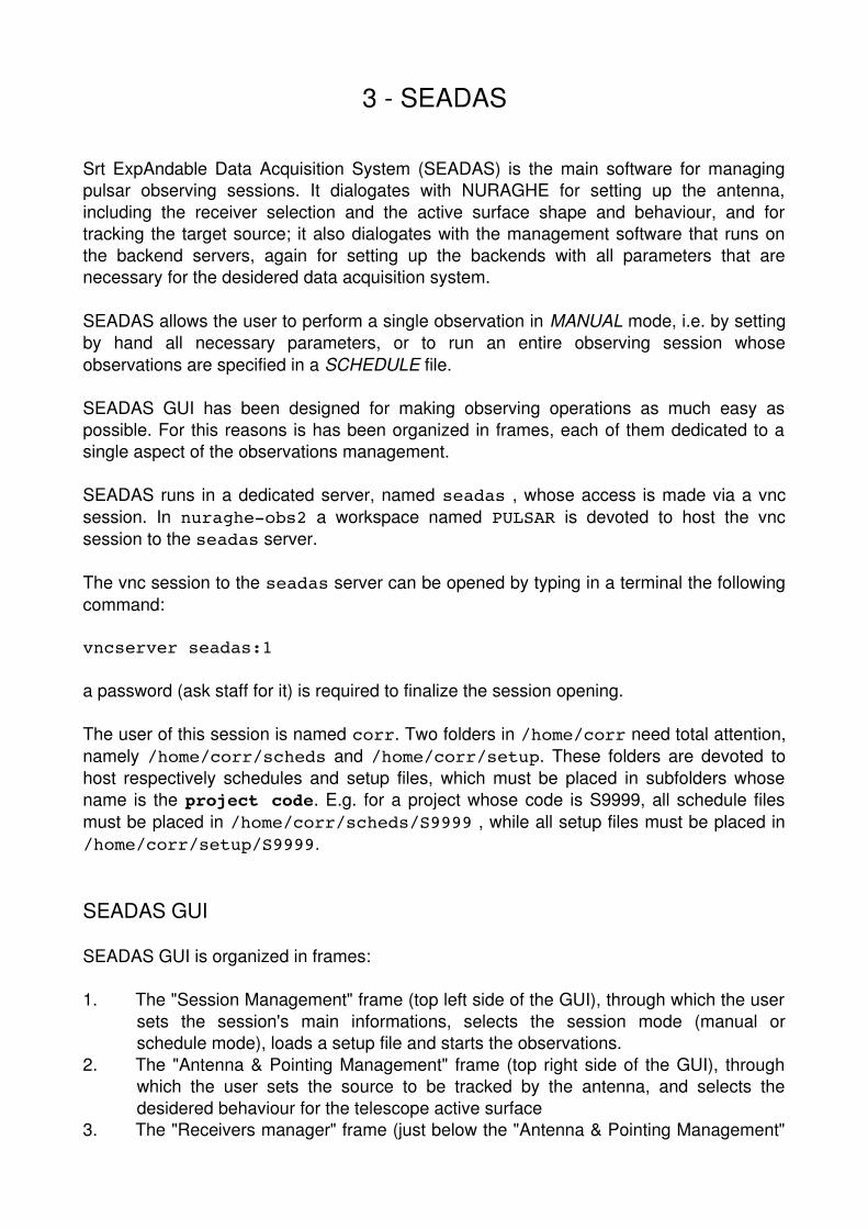
In manual mode setup files can be managed through the "Setup file" field and the "Load
setup" and "Reload setup" buttons. The name of a setup file can be directly typed in the"Setup file" field, and all informations are automatically displayed in SEADAS GUI. Thesetup file name has to be entered with its relative path to the root directory for storing allsetup files. This directory is currently set to /home/corr/setup. No other places are allowed.A setup file can be also loaded by clicking on the "Load setup" button: a system windowpops up for browsing system directories and selecting the desidered file. The "Reloadsetup" button allows to reread a setup file whose name is already displayed in the "Setupfile field".
Fields "Obs length (s)", "UTC start" and "UTC stop" allow to manage the duration of anobservation. Their meaning is, respectively, the duration of the observation, the earliestUTC at which the observation can start and the latest UTC at which the observation muststop. "UTC start" and "UTC stop" parameters are manily used in time tagged schedulesand can be ignored in manually run observations.
The button "Observe" starts a single observation in manual mode, or the first selectedobservation in a schedule managed session. The "Stop obs" button interrupts the currentobservation, whatever is the session mode. The "Suspend" button can be used in theschedule mode only: When it's pressed, the schedule is stopped at the end of the runningobservation.
Buttons "View schedule" and "View obs list" pop up two windows, "Schedule manager"and "Observation List" respectively, for managing the observation schedules.
In the upper side of the "Schedule manager" window, field "Sched file" and buttons "Loadsched" and "Reload sched" have the very same functions and or work in the very sameway like, respectively, field "Setup file" and buttons "Load setup" and "Reload setup", butfor schedules. The root directory for schedules is currently set to /home/corr/scheds. Onceselected in any allowed way, the schedule is displayed in the gray frame. Observationlines can be singularly or all at once selected. A single line is selected by clicking on it,while the entire schedule is selected by clicking the "Select all" button. Once displayed, aschedule can be directly edited in the "Schedule manager" window, by clicking on the"Start edit" button. The "Save" button allows to save all changes in the current file, the"Save as..." button opens a system window for saving the modified schedule with adifferent name, and the "Clear changes" removes all apported changes. When any buttonof these three is clicked, "Schedule Manager" exits the schedule edit mode. A schedulecan be also edited with the emacs text editor, by clicking on the "emacs edit" button. Afterall changes are saved, the schedule must be manually reloaded by clicking on either"Load sched" or "Reload sched" button.
The "Observation List" window shows all selected schedule lines. Only those lines that aredisplayed in this window will be executed. Therefore, if this window is empty, noobservations are done. Schedule lines can be rearranged in this window by a cut/pasteaction. A mouse left button click on a line removes it from the window, while a mousemiddle button click inserts the last cut line at the curson position. The last cut line can bepasted multiple times. The "Clear" button simply removes all displayed lines in the"Observation List" window.
All described actions in both "Schedule manager" and "Observation List" windows can be

done not only before starting the observations, but also while observations are in progress:the ongoing observation is not affected at all since its schedule line does not appear in the"Observation List" window.
Items in the "Antenna & Pointing Management" frame
The colored label at the top right corner of this frame indicates if the antenna control isenabled or disabled. If the control is disabled, its color is red and it displays the wordDISABLED, while the displayed word is ENABLED and its color is green if the antennacontrol is enabled. A mouse left button click on this label switches between the twosituations. Disabling the antenna control is always succesful, while the opposite requiresthat the socket connection between nuraghe and SEADAS is established. In order to runany observation, the antenna control must be ENABLED.
In manual mode, the source to be tracked can be set by typing its name in the field at thevery right of the "Source name" button. If the typed string is the name of a cataloguepulsar, its catalogue coordinates, in the frame selected by the "Coordinates" combo box,are automatically loaded. A catalogue pulsar can be also loaded by clicking the "Sourcename" button: a window pops up and a source can be selected by clicking with the mouseleft button on its line. The selected source's name and J2000 celestial coordinates are inthis way automatically displayed in the GUI. Coordinates values can be also manuallymodified.
In manual mode, the "Coordinates" combo box allows to select the coordinate system ofthe point to be tracked. Allowed values are "AZ/EL" for pointing at fixed azimuth andelevation, "J2000" for tracking a source whose coordinates are expressed in the J2000celestial frame.
Items in the "DFB" frame
The colored label at the top left corner of this frame always displays the string "DFB", andits color indicates whether the data acquisition by this backend is controlled by seadas: redmeans control disabled and socket connection closed, green means control enabled andsocket connection established. A mouse left button click on this label allows to switchbetween these two situations. While the disabling action is always succesful, the enablingaction is succesful only if the socket connection to the "DFB" is succesfully established. Ifa connection cannot be established, i.e. the colored label remains red, check if the graphictool "dfbcontroller" is running on the DFB server.
Items in the "Receivers manager" frame
The "Receiver" combo box allows to select the receiver to be used. Whenever a selectionis made, graphic items appear in this frame, through which the receiver's parameters canbe set.
At the very right of the "Receiver" combo box, the "Configure" button is present. When this

button is clicked, SEADAS sends to nuraghe all necessary parameters to effectivelyconfigure the antenna as indicated in the "Receivers manager" frame.
Two radio buttons at the rigth of the "Cal source" label switch off and on the signal'scalibration source.
When a receiver is selected, combo boxes appear below the "Attenuation levels (DB)"label. These items allow to select the signal attenuation level for the two polarizationsseparately. The button "set atten.", placed just above the "Attenuation levels (DB)" label,sends to nuraghe, when clicked, all necessary command to apply the requestedattenuations.

4 The Pulsar Digital Filterbank
The Pulsar Digital FilterBank (PDFB) is currently the only backend devoted for pulsarobservations. The detailed documentation can be found athttp://www.jb.man.ac.uk/~pulsar/observing/DFB.pdf. The reader is encouraged to read thisdocument, with particular attention to section 6.
PDFB operations are controlled through its main server, named psrdfb. The observerneeds to open a vnc session on psrdfb before starting any observing session. Innuragheobs2 a workspace called MISC can be used for hosting the vnc window on thepsrdfb.
The vnc session is be opened by giving in a nuragheobs2 terminal the followingcommand:
vncviewer psrdfb:2
a password (ask staff for it) is required to finalize the session opening.
The user of this session is named corr. The PDFB control software can be launched onlyafter the backend is up and running. In the psrdfb vnc window teh following command hasto be given:
/home/corr/software/seadas/bin/dfbcontroller
This command launches dfbcontroller, which in turn opens pdfb3 and tkds. Theobserver has to verify that pdfb3, tkds and dfbcontroller windows are all three up.
The observer must also verify that dfbcontroller is connected to tkds: a coloured labell atthe right of the tkds label indicates whether the connection has been established (greenbackground, text CONNECTED) or not (red beckground, text DISCONNECTED). If noconnection is active, by clicking on this coloured label the connection can be established.
The control mode combo box, just above the log messages frame, must always be set onDIRECT. The other option for this setting, named PASSIVE, allows to operate the PDFB inpiggyback mode. Such modality is currently allowed for the LEAP project only.
No further user actions are required for an observing session managed by SEADAS,nevertheless dfbcontroller can be used for directly operate the PDFB. Direct operations ofthe PDFB through dfbcontroller need a good knowledge of the backend, for what concernsits tecnical settings, and of pulsar astronomy for what concerns the data acquisitionsettings.
Once the observing session is finished, dfbcontroller, tkds and pfb3 have to be closedstrictly in the given order before switching the PDFB off and closing the vnc session onpsrdfb.

5 Setup files
Setup files are useful tools in both running a manual observation and preparing aschedule. In the first situation, the user can set in SEADAS all observation's parameters byloading a text file, instead of manually setting them all in the GUI. In the second situation,the structure of a schedule becomes very simple, straightforward human readable.
Setup files must be placed in folder /home/corr/setup/[project code] where[project code] is the code assigned to the project by the Time Allocation Comitee(TAC). This folder can be created by the user, it can be also organized in subfolders, andfiles can be placed in any of them.
All necessary informations can be in principle written in a single file, but this option mayresult in files containing several tens of rows. For this reason setup files can be organizedin a hierarchical scheme, namely:
1) GENERAL setup file, where all session parameters are set, and the ANTENNA andBACKENDS setup files are indicated;
2) ANTENNA setup file, where all paramters are set for configuring the antenna;3) BACKEND setup files, where all data acquisition parameters are set for the related
bakend.
It is strongly recommended to adopt the hierarchical scheme when preparing theobservation/schedule setup file. All settings for a given backend have to be placed in thesame file; settings for different backends must be placed in separated files.
In setup files the syntax for setting a parameter takes the form of a value assignment:
[keyword] = [value(s)]
where [keyword] is keyword that identifies the parameter to be set and [value(s)] isa string containing the value(s) to be assigned. Here is an example:
ProjectCode = RFITEST
A given keyword may require one or more values to be specified. In the latter case, valuesare separated by the comma ',' character. Example:
Source = J07373039A , J2000 , 07:37:51.248419 , 30:39:40.71431
Unless explicitly indicated, a keyword requires one value only to be specified. A file linecan contain the value assignment for one keyword only. Comments are also allowed insetup files. Any text placed at the right side of the # character is a comment. Examples:
Source = B0329+54 # this is a comment# this is another comment

The general setup file
The general setup file contains all informations about the observing session, the antennaconfiguration and the backend(s) to be used. It can also contain the name of a source tobe observed, possible pointing offsets with respect to the source coordinates, thetelescope azimuth sector and the observation length.
In the general setup file, settings for the antenna have the following sintax:
ANTENNA > [antenna setting]
where [antenna setting] can be:
1) Setup = [projectcode]/[file name]: this line loads the antenna's setupfile, which is mandatory located in folder /home/corr/setup/[projectcode] ,or a subfolder of it.
2) [keyword] = [value(s)]: this line assigns the value [value(s)] to theantenna's parameter identified by the keyword [keyword] (see antenna sectionsfor allowed keywords and related sintax).
Similarly, settings for backends have the following sysntax:
[backend identification code] > [backend setting]
where [backend identification code] is a three character code that identifies thebackend, and [backend setting] is one of the following strings:
1) DISABLE or ENBLE: this line disables/enables the backend2) Setup = [projectcode]/[file name]: this line loads the backend's setup
file, which is mandatory located in folder /home/corr/setup/[projectcode] ,or a subfolder of it.
3) [keyword] = [value(s)]: this line assigns the value [value(s)] to thebackend's parameter identified by the keyword [keyword] (see backends'sections for allowed keywords and related sintax).
Keywords list and syntax
AzSector(*) The telescope's azimuth sector to be used for pointing the antenna.Allowed values are CW for the clockwise sector, CCW for the couterclockwise sector,NEUTRAL for letting the pointing system to automatically choose the best sector. If unsureuse the value NEUTRAL.
ObserverName The name of the observers. Any text string is an allowed value.
ObsLength The observation length in seconds. Its allowed values are integer numbers

only.
Offsets(*) Pointing offsets with respect to the source coordinates. Two sintaxes areallowed:
Offsets = OFFNo offsets are applied to the source coordinates.
Offsets = [coordinate system],[long. offset],[lat. offset][coordinate system] is the coordinate system in which offsets value areexpressed. Allowed values are J2000 (clestial coordinates) and AZ/EL (horizontalcoordinates). [long. offset] is the offset in decimal degrees to be applied to theright ascension or the azimuth coordinate while [lat. offset] is the offset indecimal degrees to be applied to the declination or the elevation coordinate,accordingly to the the value of [coordinate system].
ProjectCode The project code, i.e. the code assigned by the TAC.
ProjectName The project name. Any text string is an allowed value.
Source(*) The source name and its coordinates. Two syntaxes are allowed.
Source = [source name]The source whose name is [source name] is set with its J2000 cataloguecoordinates.
Source = [source name],[coordinate system],[longitude],[latitude]The source whose name is [source name] is set with coordinates [longitude]and [latitude], expressed in the [coordinate system] coordinate system.Allowed values for [coordinate system] are J2000 (clestialcoordinates) and AZ/EL (horizontal coordinates). [longitude] is the rightascension or the azimuth value, [latitude] is the declination or elevation value,accordingly to the value for [coordinate system].
Keywords indicated by the (*) mark denote parameters, whose values can be set in boththe general and the antenna setup file. The sintax is the exactly the same, regardless onthe file where settings for these parameters are placed.

General setup file template:
ProjectCode = RFITEST ProjectName = RFI investigation tests ObserverName = Bachisio AngiusObsLength = 7200 Source = B0329+54AzSector = CCW Offsets = J2000,0.5,1.5ANTENNA > Setup = RFITEST/antennasetup.txtDFB > ENABLE DFB > Setup = RFITEST/dfbsearch.txtDFB > Bandwidth = 512.000

The antenna setup file
The antenna setup file contains the entries for selecting and configuring the receiver,enabling or disabling the calibration source, and setting the active surface shape. In thissetup file, entries are also allowed for the Source name and coordinates (keywordSource), the pointing offsets (keyword Offsets), and the azimuth track sector (keywordAzSector); see previous section for details about their sintax.
Keywords list and syntax
ActiveSurface The shape and behaviour of the active surface. Allowed values are:
• Parabolic The shape is set to parabolic and the surface is continuouslycontrolled.
• ParabolicFixed The shape is set to parabolic and the surface is kept fixed.• Shaped The shape is set to shaped and the surface is continuously controlled.• ShapedFixed The shape is set to shaped and the surface is kept fixec.• ReceiverDefault Each receiver has been assigned a default configuration for
the active surface. These defaults are ParabolicFixed for the LBand, PBandand LPDUAL receiver, Shaped for the CBAND receiver. If unsure use this value.
CalSource This keyword allows to switch ON and OFF the calibration source. It must beplaced after the Receiver keyword. Values are ON and OFF, with an obvious meaning.
Receiver The receiver to be used and its configuration parameters. Its sintax is:
Receiver = [receiver name],[receiver parameters]
where [receiver name] is the name of the desidered receiver and [receiverparameters] is a sequence of comma separated values. The number and meaning ofthese values depend on the selected receiver.
PBAND
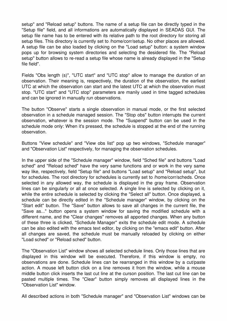
Syntax: Receiver = PBAND,[frequency filter],[polarization]
[frequency filter]: a one digit number that identifies the receiver's frequency filter(see NURAGHE manual for details);[polarization]: values are Circular or Linear with obvious meaning;
LBAND
Syntax: Receiver = LBAND,[frequency filter],[polarization],[localoscillator frequency]
[frequency filter]: a one digit number that identifies the receiver's frequency filter(see NURAGHE manual for details);[polarization]: values are Circular or Linear with obvious meaning;[local oscillator frequency]: the frequency in MHz of the local oscillator for signal's downconversion (see NURAGHE manual for the range of allowed values).
LPDUAL
Syntax: Receiver = LPDUAL,[PBAND frequency filter],[PBAND polarization],[LBAND frequency filter],[LBAND polarization],[LBAND local oscillator frequency]
[PBAND frequency filter]: a one digit number that identifies the PBANDreceiver's frequency filter (see NURAGHE manual for details);[PBAND polarization]: PBAND polarization mode: Circular or Linear;[LBAND frequency filter]: a one digit number that identifies the LBANDreceiver's frequency filter (see NURAGHE manual for details);[LBAND polarization]: LBAND polarization mode: Circular or Linear;[L_BAND local oscillator frequency]: the frequency in MHz of the local oscillator for the LBAND signal's downconversion (see NURAGHE manual for the range of allowed values).
CBAND
Syntax: Receiver = CBAND,[local oscillator frequency],[bandwidth]
[local oscillator frequency]: the frequency in MHz of the local oscillator for signal's downconversion (see NURAGHE manual for the range of allowed values).[bandwidth]: the width in MHz of the receiver's frequency filter. NURAGHE manual contains the allowed values. Due to a still unfixed bug, values have to be specified with only one decimal digit. Example: if the desidered bandwidth is 300MHz, the string 300.0 has to be specified.
Antenna setup file templates:
PBAND template:
ActiveSurface = ReceiverDefaultReceiver = PBAND,2,LinearCalSource = OFF
LBAND template:
ActiveSurface = ReceiverDefaultReceiver = LBAND,4,Linear,2188.000

CalSource = OFF
LPDUAL template:
ActiveSurface = ReceiverDefaultReceiver = LPDUAL,2,Linear,4,Linear,2188.000CalSource = OFF
CBAND template:
ActiveSurface = ReceiverDefaultReceiver = CBAND,5800.0,730.0CalSource = OFF
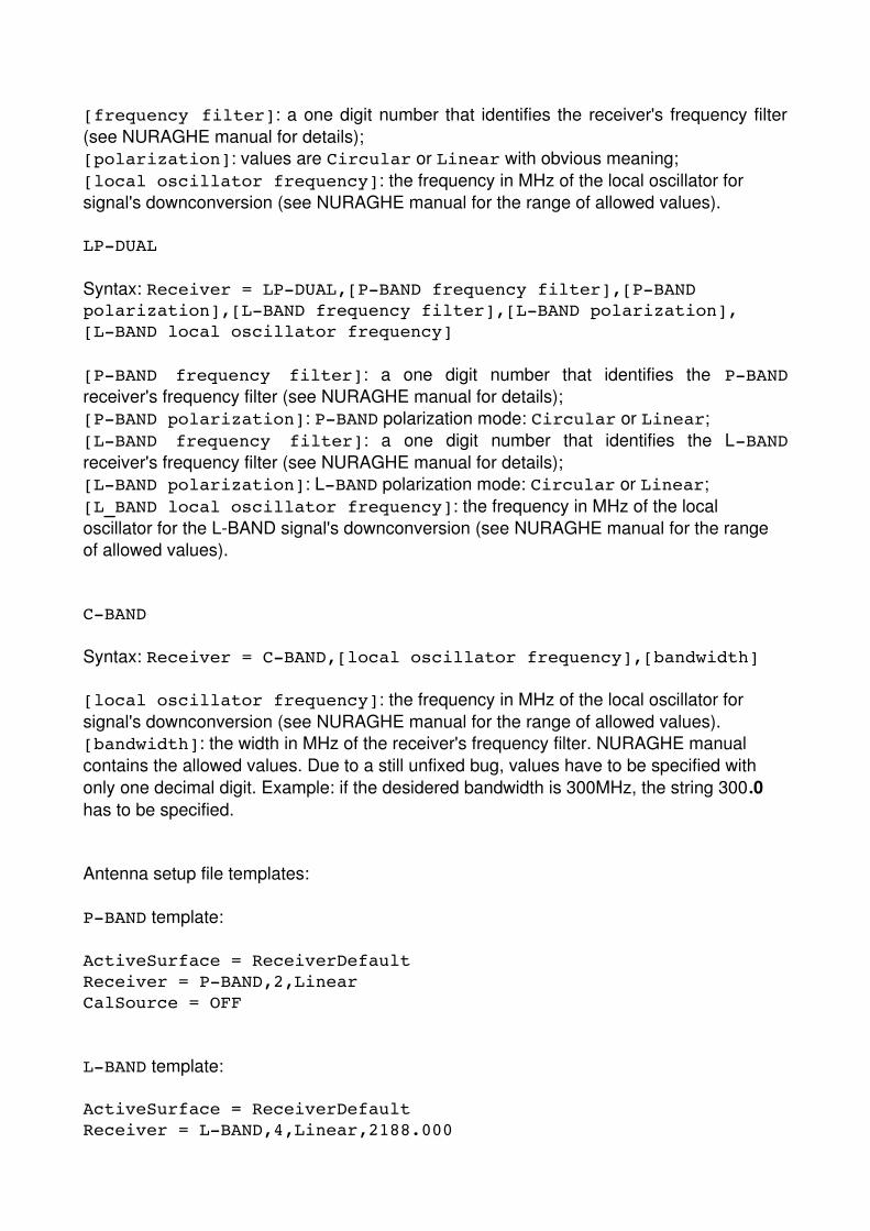
The backend setup file
The backend setup file contains entries for setting the data acquisition parameters for agiven backend. Data acquisition parameters can be divided in two groups. To the first onethose parameters belong, that are common to any backend (e.g. the central value andwidth of the frequency band, the nuber of frequency channels, etc.). To the second groupthose parameters belong, that are specific for a given backend (e.g. the cycle period forthe Pulsar Digital Filterbank). Keywords for first group parameters are illustrated in thissection, while keywords for second group parameters are illustrated in the related backendsection. Complete templates are provided for each backend at the end of the relatedsections.
Keyword list and syntax
Bandwidth The width in MHz of the frequency band (e.g. 512.000).
BitsPerSample The number of bits to represent each data sample (1,2,4,8)
ChannelWidth The width in MHz of each frequency channel (e.g. 0.500).
Frequency The value in MHz of the central frequency (e.g. 1548.000).
InvertedFreqs YES if the observing band is inverted after signal's down conversion,else NO (case insensitive).
Mode The data acquisition mode. See each backend section for the allowed values .
NumberOfChannels The number of channels in the frequency band (e.g. 512).
NumberOfPols The number of polarization to be recorded. values are 1 = totalintensity , 2 = left and right intensity only, 4 = left and right intensity and phase
ProfileBins The number of bins in profile (pulsar FOLD mode only, integer powers of2)
SubintTime The subintegration's time (seconds, pulsar FOLD mode only)
SamplingTime The sampling time (microseconds, pulsar SEARCH mode only)
Pulsar Digital Filterbank setup file
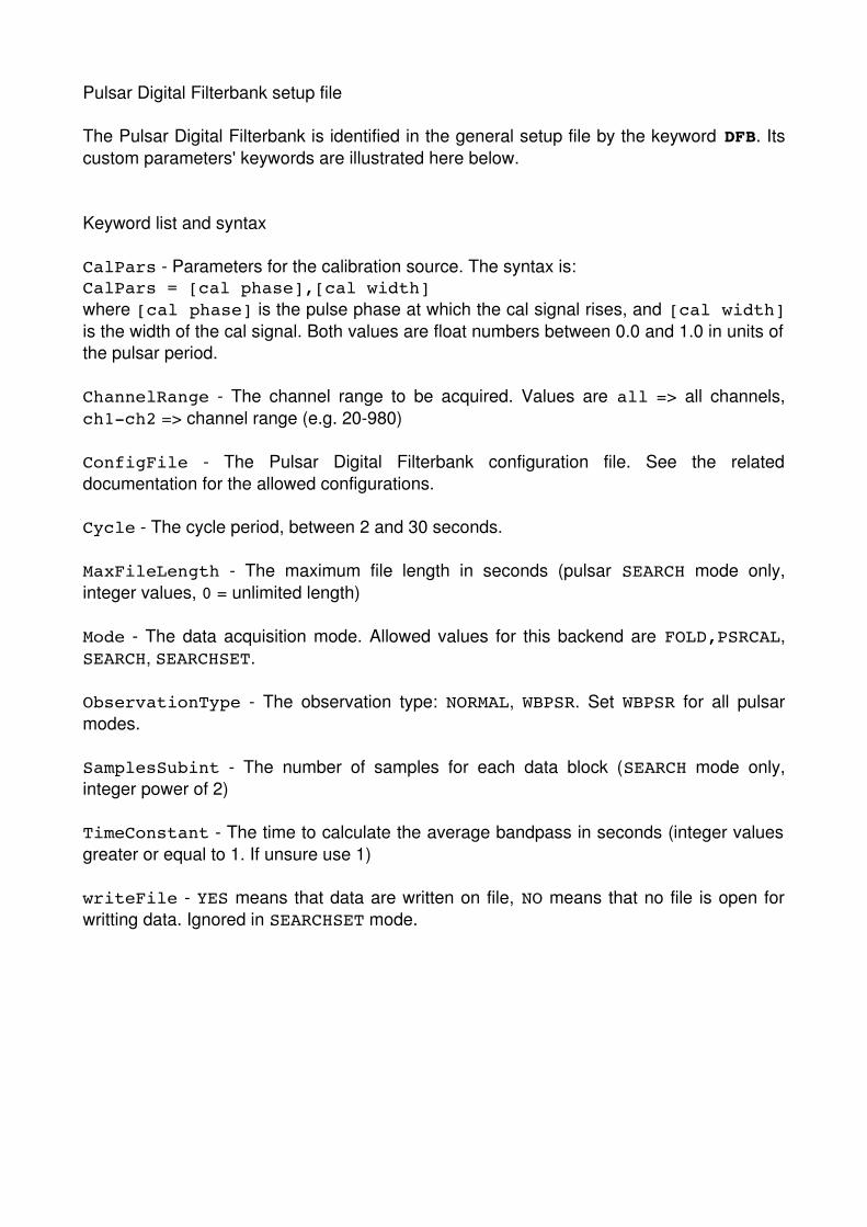
The Pulsar Digital Filterbank is identified in the general setup file by the keyword DFB. Itscustom parameters' keywords are illustrated here below.
Keyword list and syntax
CalPars Parameters for the calibration source. The syntax is:CalPars = [cal phase],[cal width]where [cal phase] is the pulse phase at which the cal signal rises, and [cal width]is the width of the cal signal. Both values are float numbers between 0.0 and 1.0 in units ofthe pulsar period.
ChannelRange The channel range to be acquired. Values are all => all channels,ch1ch2 => channel range (e.g. 20980)
ConfigFile The Pulsar Digital Filterbank configuration file. See the relateddocumentation for the allowed configurations.
Cycle The cycle period, between 2 and 30 seconds.
MaxFileLength The maximum file length in seconds (pulsar SEARCH mode only,integer values, 0 = unlimited length)
Mode The data acquisition mode. Allowed values for this backend are FOLD,PSRCAL,SEARCH, SEARCHSET.
ObservationType The observation type: NORMAL, WBPSR. Set WBPSR for all pulsarmodes.
SamplesSubint The number of samples for each data block (SEARCH mode only,integer power of 2)
TimeConstant The time to calculate the average bandpass in seconds (integer valuesgreater or equal to 1. If unsure use 1)
writeFile YES means that data are written on file, NO means that no file is open forwritting data. Ignored in SEARCHSET mode.

Pulsar Digital Filterbank template for pulsar FOLD mode
Mode = FOLD Frequency = 1548.000 Bandwidth = 512.000 InvertedFreqs = No ChannelWidth = 1.000 SubintTime = 60 NumberOfPols = 4 BitsPerSample = 8 ObservationType = WBPSR ConfigFile = pdfb3_512_512_512 ChannelRange = all writeFile = YESCycle = 10.000
Pulsar Digital Filterbank template for pulsar PSRCAL mode
Mode = PSRCAL Frequency = 1548.000 Bandwidth = 512.000 InvertedFreqs = No ChannelWidth = 1.000 SubintTime = 60 NumberOfPols = 4 BitsPerSample = 8 ObservationType = WBPSR ConfigFile = pdfb3_512_512_512 ChannelRange = all writeFile = YESCycle = 10.000CalPars = 0.25,0.50
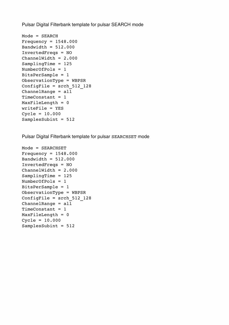
Pulsar Digital Filterbank template for pulsar SEARCH mode
Mode = SEARCHFrequency = 1548.000Bandwidth = 512.000InvertedFreqs = NOChannelWidth = 2.000SamplingTime = 125NumberOfPols = 1BitsPerSample = 1 ObservationType = WBPSRConfigFile = srch_512_128ChannelRange = all TimeConstant = 1 MaxFileLength = 0 writeFile = YESCycle = 10.000SamplesSubint = 512
Pulsar Digital Filterbank template for pulsar SEARCHSET mode
Mode = SEARCHSETFrequency = 1548.000Bandwidth = 512.000InvertedFreqs = NOChannelWidth = 2.000SamplingTime = 125NumberOfPols = 1BitsPerSample = 1 ObservationType = WBPSRConfigFile = srch_512_128ChannelRange = all TimeConstant = 1 MaxFileLength = 0 Cycle = 10.000SamplesSubint = 512

6 Schedule files
A schedule is a file that contains informations about all observations to be done in anobserving run. A schedule file is organized in rows, i.e. each row contains all informationsabout one and one only observation. Here below is a schedule example:
Source = B0329+54 ; ObsLength = 1800 ; Setup = RFITEST/seadasdfbCband.txtSource = B0355+54 ; ObsLength = 1800 ; Setup = RFITEST/seadasdfbCband.txtSource = B0950+08 ; ObsLength = 1800 ; Setup = RFITEST/seadasdfbCband.txtSource = B1929+10 ; ObsLength = 1800 ; Setup = RFITEST/seadasdfbCband.txtSource = B1933+16 ; ObsLength = 1800 ; Setup = RFITEST/seadasdfbCband.txtSource = B1952+29 ; ObsLength = 1800 ; Setup = RFITEST/seadasdfbCband.txtSource = B2020+28 ; ObsLength = 1800 ; Setup = RFITEST/seadasdfbCband.txtSource = B2021+51 ; ObsLength = 1800 ; Setup = RFITEST/seadasdfbCband.txt
Each row contains value assignments to parameters, separated by the semicoloncharacter ';'. There are no limits on the number of lines in a schedule file and of entries ineach row. It is strongly recommended to reduce as much as possible the number of entriesin each line by making use of setup files. The above schedule example also shows lineswith the essential entries, namely the source name, the observation length (keywordsSource and ObsLength, see the general setup file section for details) and the globalsetup file (keyword Setup, see below).
All parameters that can be set in a setup file, can be also set in a schedule file. They areset by using the same keywords and the same syntax as in the general setup file.Backend identification codes are also the same to be used in the general setup file.
Other parameters can be set only in a schedule file and are NOT allowed in any setup file.These parameters are name and path of the general setup file, the observation's UTC startand stop or the wait time before the data acquisition start.
The general setup file is indicated with the following syntax:
Setup = [projectcode]/[file name]
where [projectcode] is the project code and indicates that the general setup file isplaced in /home/corr/setup/[projectcode], and [file name] is the name of thefile.
The observation's UTC start, keyword ObsStartHour, and UTC stop, keywordObsStopHour, and the observation length, keyword ObsLength, allow to manage thetiming of a data acquisition. UTC start and stop allowed values are expressed in theHH:MM:SS format, if the user wants to set a value for them, or assume the value 0 if theuser wants to leave them unset. The observation length can be also left unset by settingObsLength = 1. Several timing options are allowed.
1) ObsLength = [obs. length] ; ObsStartHour = 0 ; ObsStopHour = 0The observation starts as soon as the telescope tracks the source, and lasts as indicated
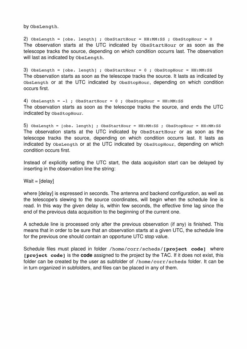
by ObsLength.
2) ObsLength = [obs. length] ; ObsStartHour = HH:MM:SS ; ObsStopHour = 0The observation starts at the UTC indicated by ObsStartHour or as soon as thetelescope tracks the source, depending on which condition occurrs last. The observationwill last as indicated by ObsLength.
3) ObsLength = [obs. length] ; ObsStartHour = 0 ; ObsStopHour = HH:MM:SSThe observation starts as soon as the telescope tracks the source. It lasts as indicated byObsLength or at the UTC indicated by ObsStopHour, depending on which conditionoccurs first.
4) ObsLength = 1 ; ObsStartHour = 0 ; ObsStopHour = HH:MM:SSThe observation starts as soon as the telescope tracks the source, and ends the UTCindicated by ObsStopHour.
5) ObsLength = [obs. length] ; ObsStartHour = HH:MM:SS ; ObsStopHour = HH:MM:SSThe observation starts at the UTC indicated by ObsStartHour or as soon as thetelescope tracks the source, depending on which condition occurrs last. It lasts asindicated by ObsLength or at the UTC indicated by ObsStopHour, depending on whichcondition occurs first.
Instead of explicitly setting the UTC start, the data acquisiton start can be delayed byinserting in the observation line the string:
Wait = [delay]
where [delay] is espressed in seconds. The antenna and backend configuration, as well asthe telescope's slewing to the source coordinates, will begin when the schedule line isread. In this way the given delay is, within few seconds, the effective time lag since theend of the previous data acquisition to the beginning of the current one.
A schedule line is processed only after the previous observation (if any) is finished. Thismeans that in order to be sure that an observation starts at a given UTC, the schedule linefor the previous one should contain an opportune UTC stop value.
Schedule files must placed in folder /home/corr/scheds/[project code] where[project code] is the code assigned to the project by the TAC. If it does not exist, thisfolder can be created by the user as subfolder of /home/corr/scheds folder. It can bein turn organized in subfolders, and files can be placed in any of them.

7 Observations checklist
This section illustrates a crude checklist for setting up and conducting a pulsar observingsession. The reader is kindly asked to have entirely read all previous sections of thisdocument before following this check while running an observing session.
Part 0: before starting the session
● Place your seadas setup files in folder: corr@seadas:/home/corr/setup/[your projectcode]
● Place your seadas schedule file in folder corr@seadas:/home/corr/scheds/[your project code]
Part 1: unstowing the antenna
If the antenna is stowed, it has to be unstowed following the procedure indicated inNURAGHE handbook. The procedure can be found at the following link:
http://discos.readthedocs.org/en/latest/user/srt/source/Checklist.html
in the box under the label Initial setup.
If the antenna azimuth position is above 82 degrees, in the OperatorInput terminal of Nuraghe console give the following command:
● goTo=*,81.9d
Part 2: opening seadas
● In nuragheobs1 open a terminal● Give the following command: vncviewer seadas:1● Type the password at prompt (ask staff for it)● In the vnc window open a terminal● Give the command: seadas● In the log frame of seadas main window check that seadas connects to nuraghe● Click on the red label at the top right corner of the Antenna and Pointing
Management frame.● Check that the clicked label becomes green and dislpays the word "ENABLED"
Part 3: setting up the DFB
● Ask the SD to verify that the DFB is correctly cabled for the requested receiver● Ask the SD to verify that the DFB is switched on

● In nuragheobs1 open a terminal● Give the command: vncviewer psrdfb:2● Type the password at prompt (ask staff for it)● Verify the system clock (see appendix A for procedure)● In the vnc wndow open a terminal● Give the command: /home/corr/software/seadas/bin/dfbcontroller● In dfbcontroller window, check that the colored label at the right of the "tkds" label is
green and displays the word "CONNECTED". If not, click on it.
Part 4: starting the observing session
All actions have to be done on SEADAS window
● Verify and adjust attenuation levels (see appendix B for procedure). This procedure must be repeated whenever the frequency bandwidth and/or receiver is changed.
Part 4a: manual driven observation
● Select "Manual" in the "Session mode" combo box● Load your setup file or maunally set all observation parameters● Modify parameters in the GUI, if necessary● Click "Observe"
Part 4b: schedule session
● Select "Schedule" in the "Session mode" combo box● Click "View obs list". A window named "Observations List" pops up● Click "View schedule". A window named "Schedule Manager" pops up● Click "Load sched" in "Schedule Manager" window. A system window pops up for
browsing system directories and selecting the schedule file● In "Schedule manager" window select schedule lines to be done (mouse left click
on each single line) or click button "Select all" for loading the entire schedule in the "Observations List" window
● If necessary, rearrange the order of the observations in the "Observations List" window (left button click == cut line ; mid button click == paste line)
● Click "Observe"
Part 5: closing the session
● Close SEADAS ● Close the vnc session on seadas● Close, in the given order, dfbcontroller, tkds and dfb3● Close the vnc session on psrdfb● Switch off the PDFB● Park the antenna by following the procedure indicated in NURAGHE manual.

APPENDIX A – Checking and setting the system clock for the Pulsar Digital Filterbank
1) Checking the system clock
● Open a shell on psrdfb● Give at prompt the command "atdc"● Hit return twice until the "Function" options are displayed● Type 1 for selecting."Terminal line"● Hit the return key until the terminal displays the system clock● Read the "Tick Phase" value, which should be of some hundreds. If much higher,
i.e. some or even several thousands, the clock has to be set as indicated in section"Setting the system clock"
● Hit the "q" key to exit atdc
2) Setting the system clock
● Open a shell on psrdfb● Give at prompt the command "atdc"● Hit return twice until the "Function" options are displayed● Type 2 for selecting "Clock control"● Hit enter until the text "Enter SU password" is displayed● Type the SU password (ask staff for it), then hit return● Type 2 for selecting the option "Set the time only"● Hit return until the following text appears:
Enter UTC in DD MMM YYYY HH MM SS (eg 1 jan 1998 13 10 15)
The entered time should be in a very next future, e.g. if the control room clockdisplays 15:23:20, enter 15 24 00.
● Click return about ten seconds before the control room clock marks the manuallyentered time
● Click again return when the control room clock exactly marks the given time.● Click the "q" key until the terminal exits from atdc and returns the prompt● Check the system clock as described in paragraph "Checking the system clock".
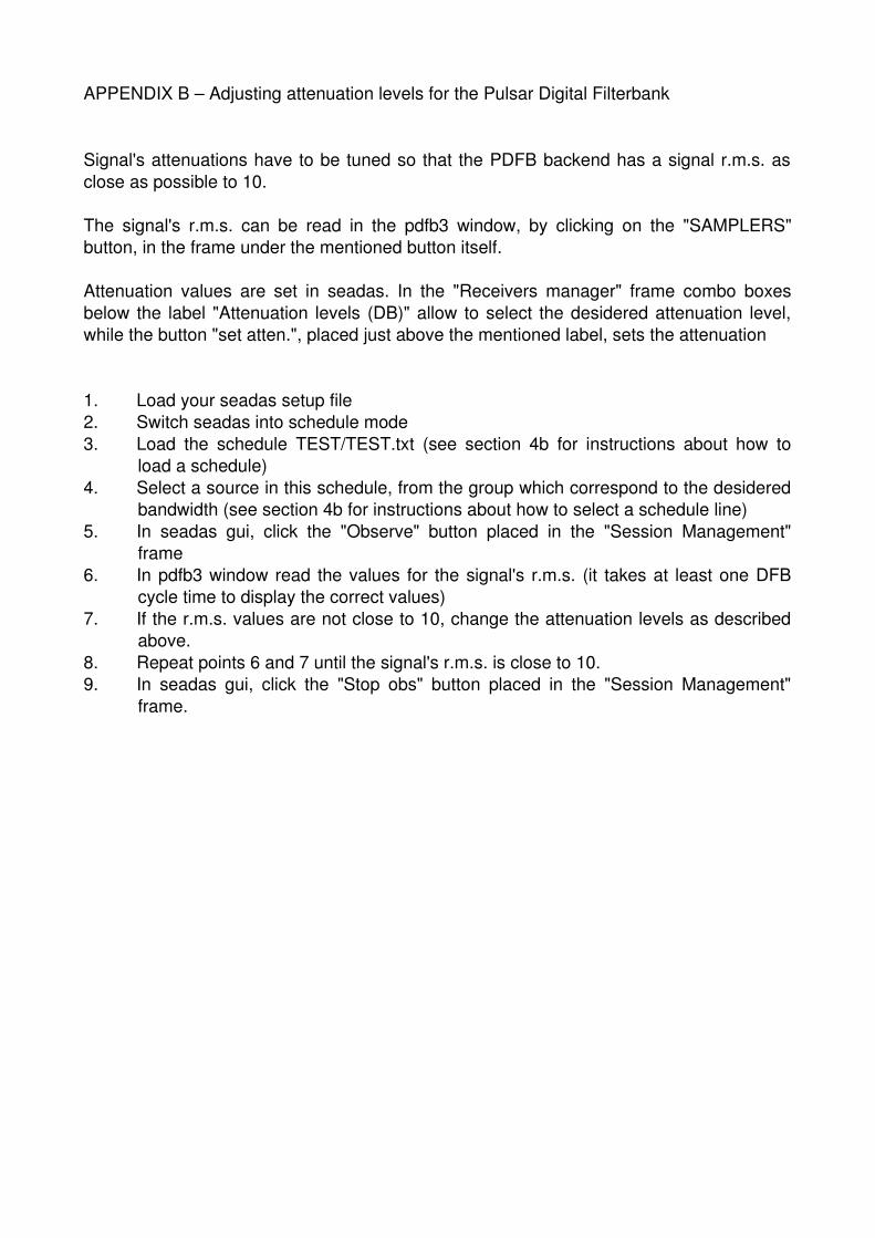
APPENDIX B – Adjusting attenuation levels for the Pulsar Digital Filterbank
Signal's attenuations have to be tuned so that the PDFB backend has a signal r.m.s. asclose as possible to 10.
The signal's r.m.s. can be read in the pdfb3 window, by clicking on the "SAMPLERS"button, in the frame under the mentioned button itself.
Attenuation values are set in seadas. In the "Receivers manager" frame combo boxesbelow the label "Attenuation levels (DB)" allow to select the desidered attenuation level,while the button "set atten.", placed just above the mentioned label, sets the attenuation
1. Load your seadas setup file2. Switch seadas into schedule mode3. Load the schedule TEST/TEST.txt (see section 4b for instructions about how to
load a schedule)4. Select a source in this schedule, from the group which correspond to the desidered
bandwidth (see section 4b for instructions about how to select a schedule line)5. In seadas gui, click the "Observe" button placed in the "Session Management"
frame6. In pdfb3 window read the values for the signal's r.m.s. (it takes at least one DFB
cycle time to display the correct values)7. If the r.m.s. values are not close to 10, change the attenuation levels as described
above.8. Repeat points 6 and 7 until the signal's r.m.s. is close to 10.9. In seadas gui, click the "Stop obs" button placed in the "Session Management"
frame.

8 Troubleshooting
This section is meant to contain all procedures to follow whenever problems occurr. Sincea procedure can be effectively exploited after a given problem erises, it cannot beconsidered complete. Therefore, indications are also given for addressing those cases notyet included in this list.
Part 1: NURAGHE problems
For any problem with NURAGHE, stop any data acquisition and refer to NURAGHEmanual at http://discos.readthedocs.org/eng/latest/user/index.html . If the problem cannotbe solved, the observing session has to be interrupted.
Part 2: SEADAS problems
0) A problem with SEADAS is either not known or persists.Observations can still be manually conducted. The antenna can be configured andoperated by giving the opportune commands in the terminal window of nuragheConsole,and the PDFB can be directly operated by acting on dfbcontroller. In this case, theobserver should also regularly check that the antenna is tracking the desidered target andthat the data acquisition with the PDFB proceeds without problems.
1) SEADAS crashes during an observation.The observer must check that a) the antenna is still tracking the desidered source, bylooking at the informative terminals of nuragheConsole and b) the PDFB is still acquiringdata by looking at dfbcontroller graphic window.If both these two checks return a positive response, the observer has to wait that the PDFB terminates its data acquisition, relaunch SEADAS and continue with the observing session
Part 3: PDFB problems
0) A problem with dfbcontroller is either not known or persists.Observations can still be manually conducted. The antenna can be configured andoperated by giving the opportune commands in the terminal window of nuragheConsole,and the PDFB can be directly operated by acting on tkds. In this case, the observer shouldalso regularly check that the antenna is tracking the desidered target and that the dataacquisition with the PDFB proceeds without problems.
1) A problem with tkds or pdfb3 is either not known or persists.If these problems cannot be solved by stopping pdfb3, tkds, and dfbcontroller anrelaunching dfbcontroller, the DFB cannot be operated. The session must be interrupted.

2) tkds fails to open when dfbcontroller is launched.The observer has to close pdfb3 and dfbcontroller, then in a terminal he/she has to givethe following commands:
corkillbcckill
Once these commands have been executed, the observer can relaunch dfbcontroller.
3) dfbcontroller crashes during an observation.The observer must check that a) the antenna is still tracking the desidered source, bylooking at the informative terminals of nuragheConsole and b) the PDFB is still acquiringdata by inspecting pdfb3 window.If both these two checks return a positive response, the observer has to wait that the PDFB terminates its data acquisition, by inspecting the in the data file thedata acquisition length. once the desidered data acquisition length has been reached, the observer clicks on thestop button in tkds window and waits for the PDFB to stop, then he/she the command fc in tkds command field. relaunch dfbcontroller and continue with the observing session


