13 Pulsed Nd:YAG Laser Applied in Microwelding Vicente Afonso Ventrella UNESP - São Paulo State University, Mechanical Engineering Department Brazil 1. Introduction The first aim of this study was to value the possibility to join, for pulsed Nd:YAG laser welding, thin foils lap joints for sealing components in corrosive environment. Typical problems in lap joint welding of thin foils include excessive distortion, absence of intimate contact between couples, melt drop-through and high levels of residual stress. The second aim of this study was to value the possibility to join thin foils and thick sheets lap joints. Typical problems in lap joint welding of dissimilar thickness include the presence of large void. Experimental investigations were carried out using a pulsed neodymium: yttrium aluminum garnet laser weld to examine the influence of the pulse energy in the characteristics of the weld fillet. The pulse energy was varied from 1.0 to 3.0 J at increments of 0.25 J with a 4 ms pulse duration. The base material used for this study was AISI 316L stainless steel foil with 100µm thickness. The welds were analyzed by optical microscopy, tensile shear tests and micro hardness. The results indicate that pulse energy control is of considerable importance to thin foil weld quality because it can generate good mechanical properties and reduce discontinuities in weld joints. The ultimate tensile strength of the welded joints increased at first and then decreased as the pulse energy increased. The process appeared to be very sensitive to the gap between couples. The focused laser beam is one of the highest power density sources available to industry today. The welding of metals was one of the first industrial applications of lasers. Laser beam welding is used widely as an important manufacturing process. It can be performed using either pulsed or continuous lasers. A pulsed laser can be used to create weld seams in thin foils by means of overlapping pulses. Pulsed laser processing is expected to be the method of choice because it allows more precise heat control compared with continuous laser processing. Commercial Nd:YAG lasers for welding applications are available from many supplies. They may be operated in three modes: 1. pulsed mode 2. continuous mode 3. Q-switched mode Pulsed mode offers a range of pulse length from 0.1 ms to continuous wave (CW) operation. Typical pulse durations for welding applications are 1-20 ms. At the low end of this range, www.intechopen.com
Transcript
13
Pulsed Nd:YAG Laser Applied in Microwelding
Vicente Afonso Ventrella
UNESP - São Paulo State University, Mechanical Engineering Department Brazil
1. Introduction
The first aim of this study was to value the possibility to join, for pulsed Nd:YAG laser
welding, thin foils lap joints for sealing components in corrosive environment. Typical
problems in lap joint welding of thin foils include excessive distortion, absence of intimate
contact between couples, melt drop-through and high levels of residual stress. The second
aim of this study was to value the possibility to join thin foils and thick sheets lap joints.
Typical problems in lap joint welding of dissimilar thickness include the presence of large
void. Experimental investigations were carried out using a pulsed neodymium: yttrium
aluminum garnet laser weld to examine the influence of the pulse energy in the
characteristics of the weld fillet. The pulse energy was varied from 1.0 to 3.0 J at increments
of 0.25 J with a 4 ms pulse duration. The base material used for this study was AISI 316L
stainless steel foil with 100µm thickness. The welds were analyzed by optical microscopy,
tensile shear tests and micro hardness. The results indicate that pulse energy control is of
considerable importance to thin foil weld quality because it can generate good mechanical
properties and reduce discontinuities in weld joints. The ultimate tensile strength of the
welded joints increased at first and then decreased as the pulse energy increased. The
process appeared to be very sensitive to the gap between couples.
The focused laser beam is one of the highest power density sources available to industry
today. The welding of metals was one of the first industrial applications of lasers. Laser
beam welding is used widely as an important manufacturing process. It can be performed
using either pulsed or continuous lasers. A pulsed laser can be used to create weld seams in
thin foils by means of overlapping pulses. Pulsed laser processing is expected to be the
method of choice because it allows more precise heat control compared with continuous
laser processing.
Commercial Nd:YAG lasers for welding applications are available from many supplies.
They may be operated in three modes:
1. pulsed mode
2. continuous mode
3. Q-switched mode
Pulsed mode offers a range of pulse length from 0.1 ms to continuous wave (CW) operation.
Typical pulse durations for welding applications are 1-20 ms. At the low end of this range,
www.intechopen.com
Nd YAG Laser
256
pulse repetition frequencies can approach 1 kHz. Q-switching of the laser output is less
useful in welding applications because the pulse duration is much shorter (< 1µs), although
pulse repetition frequencies can be high (up to 100 kHz). The higher peak power in these
pulses facilitates plasma formation and gas breakdown.
One of the prime advantages of the Nd:YAG laser over the CO2 laser is the ability to deliver
laser radiation through optical fibers. Fortuitously, the 1.06 µm output wave length of the
Nd:YAG laser falls within the wavelength range in which glass fibers have low attenuation,
so propagation of Nd:YAG laser radiation over distances of as much as several hundred
meters is possible with minimal loss.(Duley, 1999)
In general, one important problem in the experimental measurements performed at elevated
temperatures or in a corrosive environment is selecting a material that is resistant to
chemical attack and is easily formed into the desired shape. For this purpose, industrial
product parts and components are covered with stainless steel thin foils or other corrosion-
resistant material such as tantalum and Ni alloys. The significance of microtechnology has
increased dramatically over the last years, and this has created a growing need for
microwelding of thin foils. Furthermore, Nd:YAG pulsed laser welding is expected to be the
method of choice because it allows more precise heat control compared with others
processes and it reduces the heat affected zone (HAZ), residual stress and the presence of
discontinuities.
Materials play an important role in manufactured goods. Materials must possess both
acceptable properties for their intended applications and manufacturability. These criteria
hold true for micromanufacturing, in which parts have overall dimensions of less than 1
mm. The wide range of materials that can be processed by lasers includes materials for
micro-electronics, hard materials such as tungsten carbide for tool technology and very
weak and soft materials, such as polymers for medical products. Even ceramics, glass and
diamonds can be processed with laser technology to an accuracy better than 10 µm. In
comparison with classical technologies, laser processes are generally used for small and
medium lot sizes but with strongly increased material and geometric variability (Gillner et
al., 2005).
Industrial product parts and components are being made smaller to reduce energy consumption and save space, which creates a growing need for microwelding of thin foil less than 100 µm thick. For this purpose, laser processing is expected to be the method of choice because it allows more precise heat control compared with arc and plasma processing (Abe et al., 2005).
There is a trend toward increased steel microwelding applications in the medical device
manufacturing industry; these require spot sizes down to 25 µm and even smaller.
Applications include sensors with very thin membranes (where no thermal deformation is
allowed), microbonded wires with diameters of about 15 µm and welding of markers on to
stents. As medical devices become smaller in size, new challenges will appear that laser
welding will have to address (Tolinski, 2008).
Welding with a pulsed Nd:YAG laser system is characterized by periodic heating of the
weld pool by an incident high peak power density pulsed laser beam incident that allow
www.intechopen.com
Pulsed Nd:YAG Laser Applied in Microwelding
257
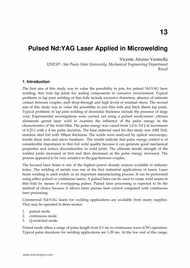
Fig. 1. Chemical seal welded by pulsed Nd:YAG laser.
www.intechopen.com
Nd YAG Laser
258
melting and solidification to take place consecutively. The welding speed is defined by the
overlap, the pulse repetition rate and the focus diameter. However, due to the very high
peak power density involved in pulsed laser welding, the solidification time is shorter than
that using a continuous laser or conventional welds. A combination of process parameters
such as pulse energy [Ep], pulse duration [tp], repetition rate [Rr], beam spot size [Фb] and
welding speed [v] determines the welding mode, that is, conduction or keyhole (Ion, 2005;
Duley, 1999 and Steen, 2005).
Research examining the Nd:YAG laser for continuous welding, pulsed welding, dissimilar
sheet welding and coated sheet welding has been published. Kim et al. (2001) reported
successful welding of Inconel 600 tubular components of nuclear power plant using a
pulsed Nd:YAG laser. Berretta et al. (2007) using a homemade Nd:YAG Pulsed Laser
System studied dissimilar welding of austenitic AISI 304 and martensitic AISI 420 stainless
steel. Ping and Molian (2008) utilized a nanosecond pulsed Nd:YAG laser system to weld 60
µm of thin AISI 304 stainless steel foil.
This study investigates the use of an Nd:YAG laser operating in pulsed mode for welding a
100 µm thick AISI 316L stainless steel thin foil. The effect of pulse energy on weld joint
characteristics is studied, and a discontinuity-free welding structure with good mechanical
properties is proposed. Figure 1 shows a chemical seal where 316L thin foil is joined with a
thickened body by pulsed Nd:YAG laser welding.
2. Experimental study
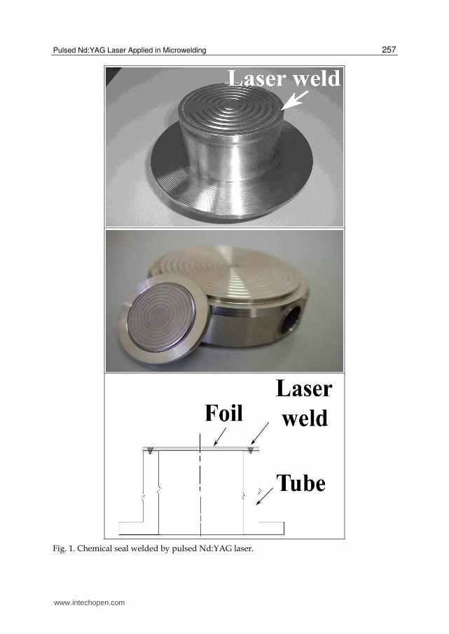
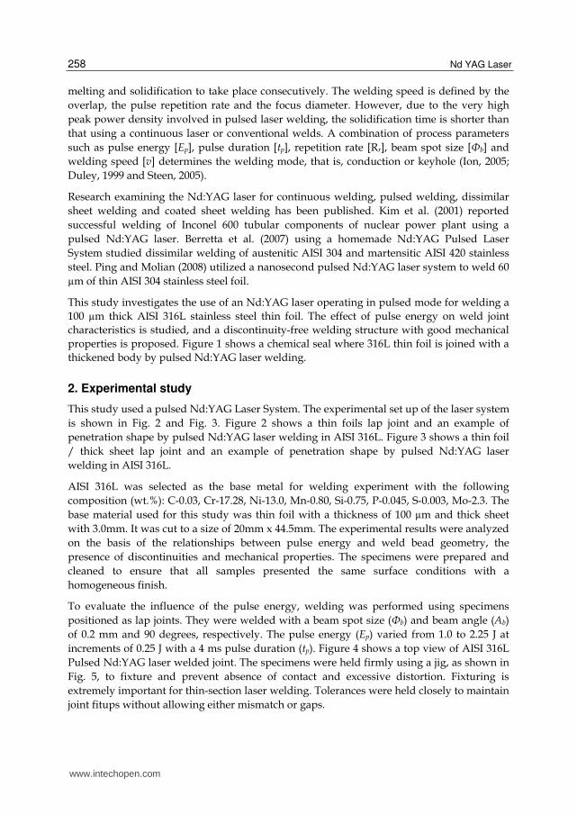
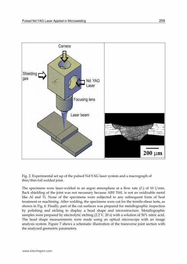
This study used a pulsed Nd:YAG Laser System. The experimental set up of the laser system
is shown in Fig. 2 and Fig. 3. Figure 2 shows a thin foils lap joint and an example of
penetration shape by pulsed Nd:YAG laser welding in AISI 316L. Figure 3 shows a thin foil
/ thick sheet lap joint and an example of penetration shape by pulsed Nd:YAG laser
welding in AISI 316L.
AISI 316L was selected as the base metal for welding experiment with the following
base material used for this study was thin foil with a thickness of 100 µm and thick sheet
with 3.0mm. It was cut to a size of 20mm x 44.5mm. The experimental results were analyzed
on the basis of the relationships between pulse energy and weld bead geometry, the
presence of discontinuities and mechanical properties. The specimens were prepared and
cleaned to ensure that all samples presented the same surface conditions with a
homogeneous finish.
To evaluate the influence of the pulse energy, welding was performed using specimens
positioned as lap joints. They were welded with a beam spot size (Фb) and beam angle (Ab)
of 0.2 mm and 90 degrees, respectively. The pulse energy (Ep) varied from 1.0 to 2.25 J at
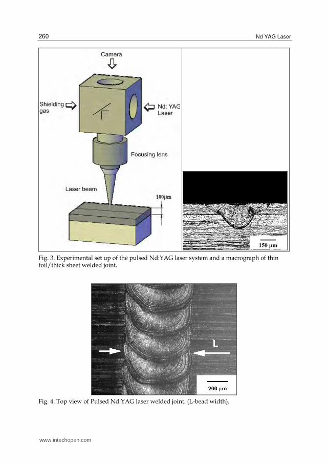
increments of 0.25 J with a 4 ms pulse duration (tp). Figure 4 shows a top view of AISI 316L
Pulsed Nd:YAG laser welded joint. The specimens were held firmly using a jig, as shown in
Fig. 5, to fixture and prevent absence of contact and excessive distortion. Fixturing is
extremely important for thin-section laser welding. Tolerances were held closely to maintain
joint fitups without allowing either mismatch or gaps.
www.intechopen.com
Pulsed Nd:YAG Laser Applied in Microwelding
259
Fig. 2. Experimental set up of the pulsed Nd:YAG laser system and a macrograph of thin/thin foil welded joint.
The specimens were laser-welded in an argon atmosphere at a flow rate (Fr) of 10 l/min.
Back shielding of the joint was not necessary because AISI 316L is not an oxidizable metal
like Al and Ti. None of the specimens were subjected to any subsequent form of heat
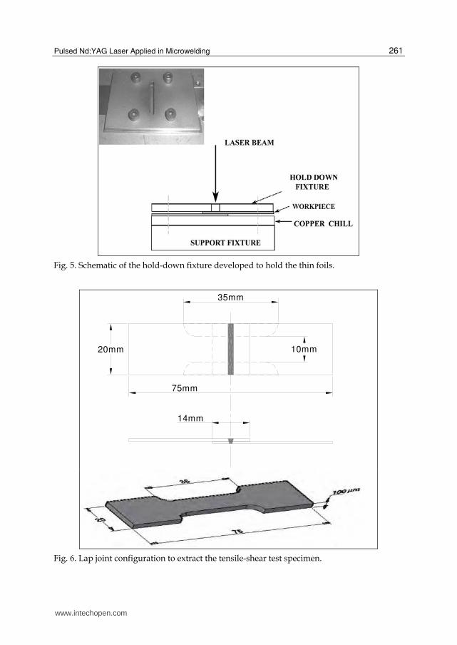
treatment or machining. After welding, the specimens were cut for the tensile-shear tests, as
shown in Fig. 6. Finally, part of the cut surfaces was prepared for metallographic inspection
by polishing and etching to display a bead shape and microstructure. Metallographic
samples were prepared by electrolytic etching (2.2 V, 20 s) with a solution of 50% nitric acid.
The bead shape measurements were made using an optical microscope with an image
analysis system. Figure 7 shows a schematic illustration of the transverse joint section with
the analyzed geometric parameters.
www.intechopen.com
Nd YAG Laser
260
Fig. 3. Experimental set up of the pulsed Nd:YAG laser system and a macrograph of thin foil/thick sheet welded joint.
Fig. 4. Top view of Pulsed Nd:YAG laser welded joint. (L-bead width).
www.intechopen.com
Pulsed Nd:YAG Laser Applied in Microwelding
261
Fig. 5. Schematic of the hold-down fixture developed to hold the thin foils.
35mm
20mm 10mm
75mm
14mm
Fig. 6. Lap joint configuration to extract the tensile-shear test specimen.
www.intechopen.com
Nd YAG Laser
262
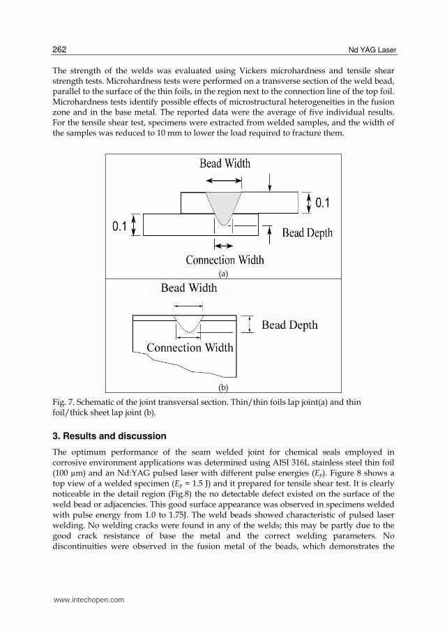
The strength of the welds was evaluated using Vickers microhardness and tensile shear strength tests. Microhardness tests were performed on a transverse section of the weld bead, parallel to the surface of the thin foils, in the region next to the connection line of the top foil. Microhardness tests identify possible effects of microstructural heterogeneities in the fusion zone and in the base metal. The reported data were the average of five individual results. For the tensile shear test, specimens were extracted from welded samples, and the width of the samples was reduced to 10 mm to lower the load required to fracture them.
(a)
(b)
Fig. 7. Schematic of the joint transversal section. Thin/thin foils lap joint(a) and thin foil/thick sheet lap joint (b).
3. Results and discussion
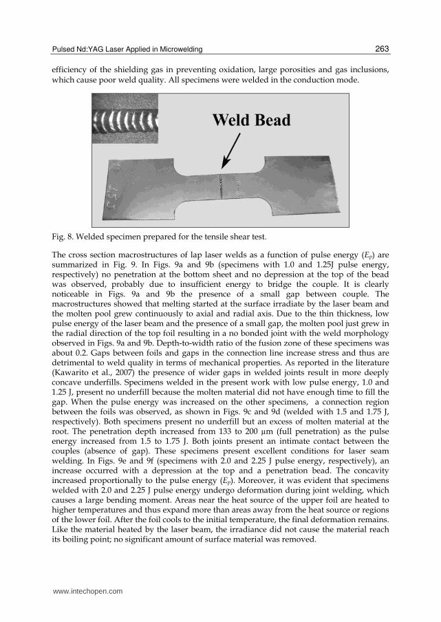
The optimum performance of the seam welded joint for chemical seals employed in corrosive environment applications was determined using AISI 316L stainless steel thin foil (100 µm) and an Nd:YAG pulsed laser with different pulse energies (Ep). Figure 8 shows a top view of a welded specimen (Ep = 1.5 J) and it prepared for tensile shear test. It is clearly noticeable in the detail region (Fig.8) the no detectable defect existed on the surface of the weld bead or adjacencies. This good surface appearance was observed in specimens welded with pulse energy from 1.0 to 1.75J. The weld beads showed characteristic of pulsed laser welding. No welding cracks were found in any of the welds; this may be partly due to the good crack resistance of base the metal and the correct welding parameters. No discontinuities were observed in the fusion metal of the beads, which demonstrates the
www.intechopen.com
Pulsed Nd:YAG Laser Applied in Microwelding
263
efficiency of the shielding gas in preventing oxidation, large porosities and gas inclusions, which cause poor weld quality. All specimens were welded in the conduction mode.
Fig. 8. Welded specimen prepared for the tensile shear test.
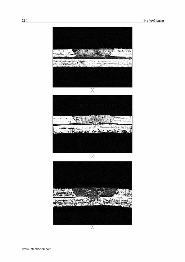
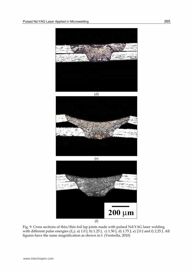
The cross section macrostructures of lap laser welds as a function of pulse energy (Ep) are summarized in Fig. 9. In Figs. 9a and 9b (specimens with 1.0 and 1.25J pulse energy, respectively) no penetration at the bottom sheet and no depression at the top of the bead was observed, probably due to insufficient energy to bridge the couple. It is clearly noticeable in Figs. 9a and 9b the presence of a small gap between couple. The macrostructures showed that melting started at the surface irradiate by the laser beam and the molten pool grew continuously to axial and radial axis. Due to the thin thickness, low pulse energy of the laser beam and the presence of a small gap, the molten pool just grew in the radial direction of the top foil resulting in a no bonded joint with the weld morphology observed in Figs. 9a and 9b. Depth-to-width ratio of the fusion zone of these specimens was about 0.2. Gaps between foils and gaps in the connection line increase stress and thus are detrimental to weld quality in terms of mechanical properties. As reported in the literature (Kawarito et al., 2007) the presence of wider gaps in welded joints result in more deeply concave underfills. Specimens welded in the present work with low pulse energy, 1.0 and 1.25 J, present no underfill because the molten material did not have enough time to fill the gap. When the pulse energy was increased on the other specimens, a connection region between the foils was observed, as shown in Figs. 9c and 9d (welded with 1.5 and 1.75 J, respectively). Both specimens present no underfill but an excess of molten material at the root. The penetration depth increased from 133 to 200 µm (full penetration) as the pulse energy increased from 1.5 to 1.75 J. Both joints present an intimate contact between the couples (absence of gap). These specimens present excellent conditions for laser seam welding. In Figs. 9e and 9f (specimens with 2.0 and 2.25 J pulse energy, respectively), an increase occurred with a depression at the top and a penetration bead. The concavity increased proportionally to the pulse energy (Ep). Moreover, it was evident that specimens welded with 2.0 and 2.25 J pulse energy undergo deformation during joint welding, which causes a large bending moment. Areas near the heat source of the upper foil are heated to higher temperatures and thus expand more than areas away from the heat source or regions of the lower foil. After the foil cools to the initial temperature, the final deformation remains. Like the material heated by the laser beam, the irradiance did not cause the material reach its boiling point; no significant amount of surface material was removed.
www.intechopen.com
Nd YAG Laser
264
(a)
(b)
(c)
www.intechopen.com
Pulsed Nd:YAG Laser Applied in Microwelding
265
(d)
(e)
(f)
Fig. 9. Cross sections of thin/thin foil lap joints made with pulsed Nd:YAG laser welding with different pulse energies (Ep): a) 1.0 J, b) 1.25 J, c) 1.50 J, d) 1.75 J, e) 2.0 J and f) 2.25 J. All figures have the same magnification as shown in f. (Ventrella, 2010)
www.intechopen.com
Nd YAG Laser
266
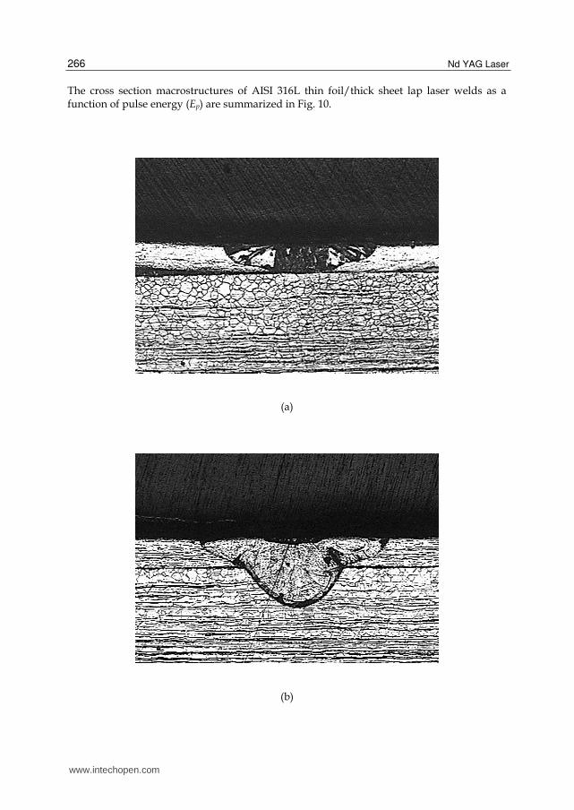
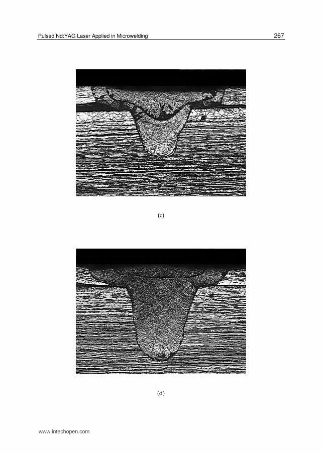
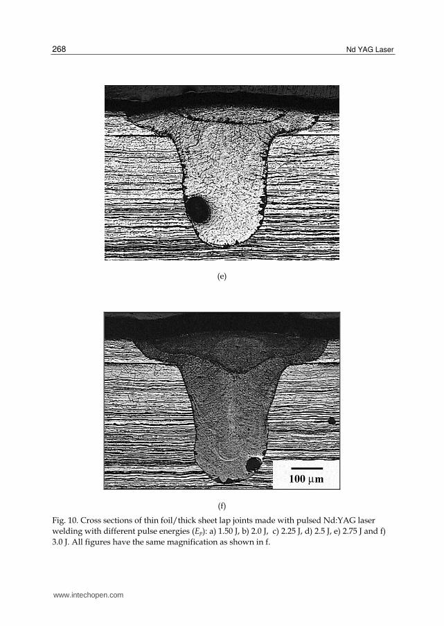
The cross section macrostructures of AISI 316L thin foil/thick sheet lap laser welds as a function of pulse energy (Ep) are summarized in Fig. 10.
(a)
(b)
www.intechopen.com
Pulsed Nd:YAG Laser Applied in Microwelding
267
(c)
(d)
www.intechopen.com
Nd YAG Laser
268
(e)
(f)
Fig. 10. Cross sections of thin foil/thick sheet lap joints made with pulsed Nd:YAG laser
welding with different pulse energies (Ep): a) 1.50 J, b) 2.0 J, c) 2.25 J, d) 2.5 J, e) 2.75 J and f)
3.0 J. All figures have the same magnification as shown in f.
www.intechopen.com
Pulsed Nd:YAG Laser Applied in Microwelding
269
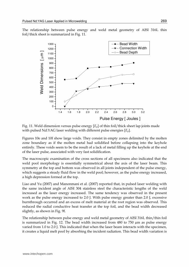
The relationship between pulse energy and weld metal geometry of AISI 316L thin foil/thick sheet is summarized in Fig. 11.
1.4 1.6 1.8 2.0 2.2 2.4 2.6 2.8 3.0 3.2
0
100
200
300
400
500
600
700
800
900
1000
1100
1200
1300W
eld
Dim
ensio
ns
[ m
]
Pulse Energy [ Joules ]
Bead Width
Connection Width
Bead Depth
Fig. 11. Weld dimension versus pulse energy [Ep] of thin foil/thick sheet lap joints made with pulsed Nd:YAG laser welding with different pulse energies [Ep].
Figures 10e and 10f show large voids. They consist in empty zones delimited by the molten
zone boundary as if the molten metal had solidified before collapsing into the keyhole
entirely. These voids seem to be the result of a lack of metal filling up the keyhole at the end
of the laser pulse, associated with very fast solidification.
The macroscopic examination of the cross sections of all specimens also indicated that the
weld pool morphology is essentially symmetrical about the axis of the laser beam. This
symmetry at the top and bottom was observed in all joints independent of the pulse energy,
which suggests a steady fluid flow in the weld pool; however, as the pulse energy increased,
a high depression formed at the top.
Liao and Yu (2007) and Manonmani et al. (2007) reported that, in pulsed laser welding with
the same incident angle of AISI 304 stainless steel the characteristic lengths of the weld
increased as the laser energy increased. The same tendency was observed in the present
work as the pulse energy increased to 2.0 J. With pulse energy greater than 2.0 J, excessive
burnthrough occurred and an excess of melt material at the root region was observed. This
reduced the radial conductive heat transfer at the top foil, and the bead width decreased
slightly, as shown in Fig. 9f.
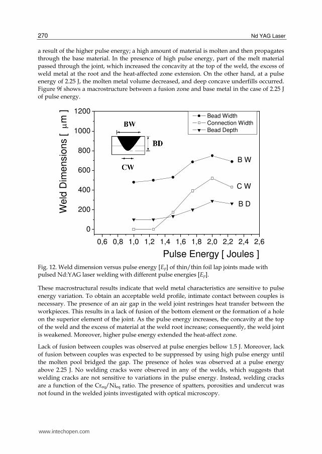
The relationship between pulse energy and weld metal geometry of AISI 316L thin/thin foil
is summarized in Fig. 12. The bead width increased from 480 to 750 µm as pulse energy
varied from 1.0 to 2.0 J. This indicated that when the laser beam interacts with the specimen,
it creates a liquid melt pool by absorbing the incident radiation. This bead width variation is
www.intechopen.com
Nd YAG Laser
270
a result of the higher pulse energy; a high amount of material is molten and then propagates
through the base material. In the presence of high pulse energy, part of the melt material
passed through the joint, which increased the concavity at the top of the weld, the excess of
weld metal at the root and the heat-affected zone extension. On the other hand, at a pulse
energy of 2.25 J, the molten metal volume decreased, and deep concave underfills occurred.
Figure 9f shows a macrostructure between a fusion zone and base metal in the case of 2.25 J
of pulse energy.
0,6 0,8 1,0 1,2 1,4 1,6 1,8 2,0 2,2 2,4 2,6
0
200
400
600
800
1000
1200
Pulse Energy [ Joules ]
Bead Width
Connection Width
Bead Depth
B W
C W
B D
We
ld D
ime
nsio
ns [
m
]
Fig. 12. Weld dimension versus pulse energy [Ep] of thin/thin foil lap joints made with pulsed Nd:YAG laser welding with different pulse energies [Ep].
These macrostructural results indicate that weld metal characteristics are sensitive to pulse
energy variation. To obtain an acceptable weld profile, intimate contact between couples is
necessary. The presence of an air gap in the weld joint restringes heat transfer between the
workpieces. This results in a lack of fusion of the bottom element or the formation of a hole
on the superior element of the joint. As the pulse energy increases, the concavity at the top
of the weld and the excess of material at the weld root increase; consequently, the weld joint
is weakened. Moreover, higher pulse energy extended the heat-affect zone.
Lack of fusion between couples was observed at pulse energies bellow 1.5 J. Moreover, lack
of fusion between couples was expected to be suppressed by using high pulse energy until
the molten pool bridged the gap. The presence of holes was observed at a pulse energy
above 2.25 J. No welding cracks were observed in any of the welds, which suggests that
welding cracks are not sensitive to variations in the pulse energy. Instead, welding cracks
are a function of the Creq/Nieq ratio. The presence of spatters, porosities and undercut was
not found in the welded joints investigated with optical microscopy.
www.intechopen.com
Pulsed Nd:YAG Laser Applied in Microwelding
271
The HAZ displays the effect of temperature cycling to a peak temperature, Tmax, which is less than the melting point but may be sufficient to initiate other transformations. The cooling rate of steel, in the HAZ, may approach 1000°C/s but varies with location, as does Tmax. The grains in the heat-affected zone were coarsened as the pulse energy [Ep] increased. This phenomenon can be explained by the cooling rate change. An increase in the pulse energy decreased the cooling rate. A slower cooling rate during solidification allowed more time for grain coarsening. In laser welding the heat-affected zones are much narrower than those generated by conventional welding process and are not likely to be sensitized to corrosion.
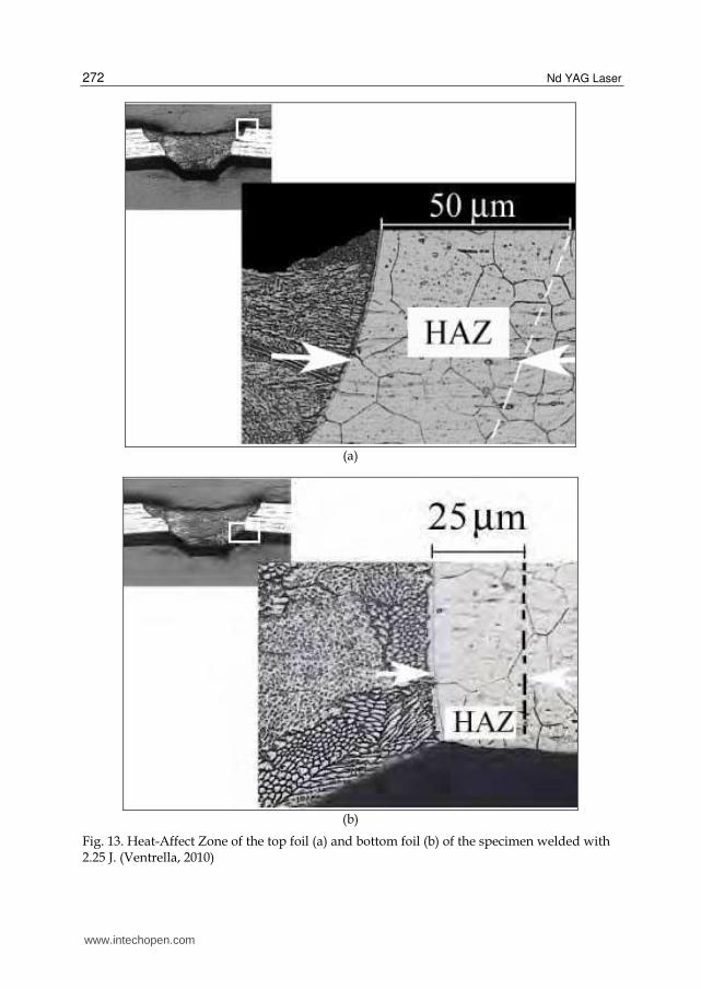
Analyses of the Heat-Affect Zone (HAZ) showed that it increased as the pulse energy increased. For all tested specimens the top foil HAZ is larger than the bottom foil HAZ, as shown in Figs. 13a and 13b. This is strongly dependent with the beam energy, conductive heat transfer and with a perfect contact between couple (presence or not of air gap). It is different processing material with a determined thickness than two foils of the same material with half of the thickness in a lap joint configuration. Air gap acts as a barrier to heat transfer. In this situation most of the beam energy can be consumed on the side exposed to the laser beam, which results in a large heat-affected zone or bead perforation.
Figure 14 shows a microscopic examination of the heat-affect zone extension of the top and
bottom foils of the specimen welded with 2.25 J. The grains in HAZ are coarsened, and the
extension of the heat-affected zone is approximately 50 and 25 µm at the top and bottom
foils, respectively. This observation in thin foils seems to contradict the expected narrow
heat-affected zone for the laser welding process. The top and bottom HAZ width of the
weld becomes obviously larger when the pulse energy (Ep) increases. The HAZ width
difference between the top and the bottom becomes smaller as the pulse energy increases, so
the cooling rate decreases with increasing pulse energy. Therefore, when the pulse energy is
higher, a higher volume of metal is melted and the welding heat has more time to be
conducted into the bottom from the top.
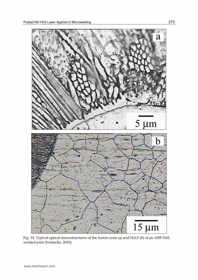
Light micrographs of the specimens showed a fine-grained microstructure that is essentially cellular-dendritic in the fusion zone. This type of microstructure is a result of high cooling rates, which are typical of the laser welding process. The formation of a given solidification structure morphology is determined by the G/R ratio (G=temperature gradient, R=growth rate) during solidification. Cellular growth structures form rather than dendritic structure if G/R ratio is high (Molian, 2007).
Figure 14a shows the fusion line solidification structure at the top of the weld where the un-
melted base metal grains act as substrates for nucleation of the fusion zone columnar grains
(epitaxial growth), which are perpendicular to the fusion boundary. Figure 14b shows the
heat affected zone at the bottom of the joint where the effects of the large thermal gradient in
this region are evident. Comparing thin and thick foil welding, it can be concluded that the
grains in the solid state coarsen with decreasing parent metal thickness. This shows that the
volume of the parent metal plays an important role during the welding thermal cycle. As the
material volume decreases, the time to cooling increases and the heat-affected zone
appearance coarsens. This indicates that in thin foil welding, heat-affected zone control is of
considerable importance for welded joint quality.
www.intechopen.com
Nd YAG Laser
272
(a)
(b)
Fig. 13. Heat-Affect Zone of the top foil (a) and bottom foil (b) of the specimen welded with 2.25 J. (Ventrella, 2010)
www.intechopen.com
Pulsed Nd:YAG Laser Applied in Microwelding
273
Fig. 14. Typical optical microstructures of the fusion zone (a) and HAZ (b) of an AISI 316L welded joint (Ventrella, 2010).
www.intechopen.com
Nd YAG Laser
274
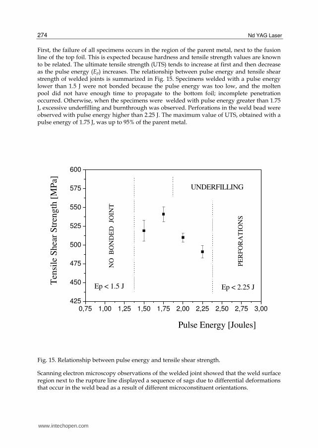
First, the failure of all specimens occurs in the region of the parent metal, next to the fusion line of the top foil. This is expected because hardness and tensile strength values are known to be related. The ultimate tensile strength (UTS) tends to increase at first and then decrease as the pulse energy (Ep) increases. The relationship between pulse energy and tensile shear strength of welded joints is summarized in Fig. 15. Specimens welded with a pulse energy lower than 1.5 J were not bonded because the pulse energy was too low, and the molten pool did not have enough time to propagate to the bottom foil; incomplete penetration occurred. Otherwise, when the specimens were welded with pulse energy greater than 1.75 J, excessive underfilling and burnthrough was observed. Perforations in the weld bead were observed with pulse energy higher than 2.25 J. The maximum value of UTS, obtained with a pulse energy of 1.75 J, was up to 95% of the parent metal.
Fig. 15. Relationship between pulse energy and tensile shear strength.
Scanning electron microscopy observations of the welded joint showed that the weld surface region next to the rupture line displayed a sequence of sags due to differential deformations that occur in the weld bead as a result of different microconstituent orientations.
www.intechopen.com
Pulsed Nd:YAG Laser Applied in Microwelding
275
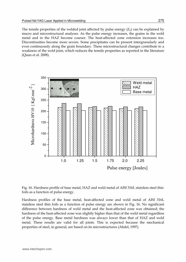
The tensile properties of the welded joint affected by pulse energy (Ep) can be explained by macro and microstructural analyses. As the pulse energy increases, the grains in the weld metal and in the HAZ become coarser. The heat-affected zone extension increases too. Discontinuities become more severe. Some precipitates can be present intergranularly and even continuously along the grain boundary. These microstructural changes contribute to a weakness of the weld joint, which reduces the tensile properties as reported in the literature (Quan et al. 2008).
0
50
100
150
200
250
300
350
Mic
rohar
dnes
s H
V10
[ K
gf.
mm
-2 ]
Pulse energy [Joules]
Weld metal
HAZ
Base metal
1.0 1.25 1.5 1.75 2.0 2.25
Fig. 16. Hardness profile of base metal, HAZ and weld metal of AISI 316L stainless steel thin foils as a function of pulse energy.
Hardness profiles of the base metal, heat-affected zone and weld metal of AISI 316L
stainless steel thin foils as a function of pulse energy are shown in Fig. 16. No significant
difference between hardness of weld metal and the heat-affected zone was obtained; the
hardness of the heat-affected zone was slightly higher than that of the weld metal regardless
of the pulse energy. Base metal hardness was always lower than that of HAZ and weld
metal. These results are valid for all joints. This is expected because the mechanical
properties of steel, in general, are based on its microstructures (Abdel, 1997).
www.intechopen.com
Nd YAG Laser
276
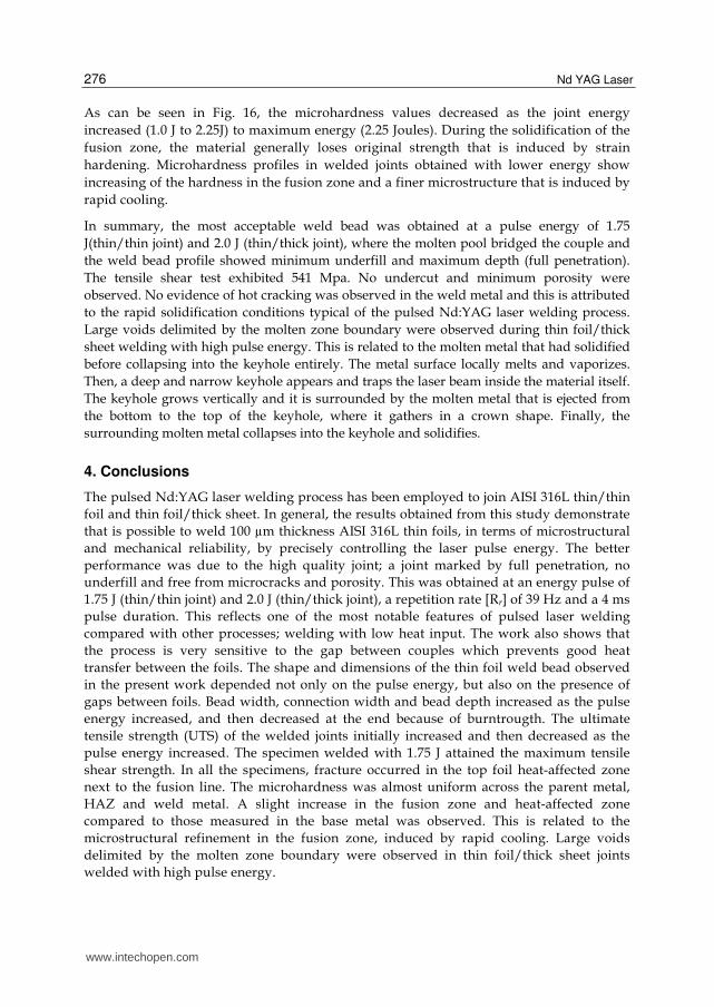
As can be seen in Fig. 16, the microhardness values decreased as the joint energy
increased (1.0 J to 2.25J) to maximum energy (2.25 Joules). During the solidification of the
fusion zone, the material generally loses original strength that is induced by strain
hardening. Microhardness profiles in welded joints obtained with lower energy show
increasing of the hardness in the fusion zone and a finer microstructure that is induced by
rapid cooling.
In summary, the most acceptable weld bead was obtained at a pulse energy of 1.75
J(thin/thin joint) and 2.0 J (thin/thick joint), where the molten pool bridged the couple and
the weld bead profile showed minimum underfill and maximum depth (full penetration).
The tensile shear test exhibited 541 Mpa. No undercut and minimum porosity were
observed. No evidence of hot cracking was observed in the weld metal and this is attributed
to the rapid solidification conditions typical of the pulsed Nd:YAG laser welding process.
Large voids delimited by the molten zone boundary were observed during thin foil/thick
sheet welding with high pulse energy. This is related to the molten metal that had solidified
before collapsing into the keyhole entirely. The metal surface locally melts and vaporizes.
Then, a deep and narrow keyhole appears and traps the laser beam inside the material itself.
The keyhole grows vertically and it is surrounded by the molten metal that is ejected from
the bottom to the top of the keyhole, where it gathers in a crown shape. Finally, the
surrounding molten metal collapses into the keyhole and solidifies.
4. Conclusions
The pulsed Nd:YAG laser welding process has been employed to join AISI 316L thin/thin
foil and thin foil/thick sheet. In general, the results obtained from this study demonstrate
that is possible to weld 100 µm thickness AISI 316L thin foils, in terms of microstructural
and mechanical reliability, by precisely controlling the laser pulse energy. The better
performance was due to the high quality joint; a joint marked by full penetration, no
underfill and free from microcracks and porosity. This was obtained at an energy pulse of
1.75 J (thin/thin joint) and 2.0 J (thin/thick joint), a repetition rate [Rr] of 39 Hz and a 4 ms
pulse duration. This reflects one of the most notable features of pulsed laser welding
compared with other processes; welding with low heat input. The work also shows that
the process is very sensitive to the gap between couples which prevents good heat
transfer between the foils. The shape and dimensions of the thin foil weld bead observed
in the present work depended not only on the pulse energy, but also on the presence of
gaps between foils. Bead width, connection width and bead depth increased as the pulse
energy increased, and then decreased at the end because of burntrougth. The ultimate
tensile strength (UTS) of the welded joints initially increased and then decreased as the
pulse energy increased. The specimen welded with 1.75 J attained the maximum tensile
shear strength. In all the specimens, fracture occurred in the top foil heat-affected zone
next to the fusion line. The microhardness was almost uniform across the parent metal,
HAZ and weld metal. A slight increase in the fusion zone and heat-affected zone
compared to those measured in the base metal was observed. This is related to the
microstructural refinement in the fusion zone, induced by rapid cooling. Large voids
delimited by the molten zone boundary were observed in thin foil/thick sheet joints
welded with high pulse energy.
www.intechopen.com
Pulsed Nd:YAG Laser Applied in Microwelding
277
5. Acknowledgments
The authors gratefully acknowledge the financial support of CNPq and Mechanical
Engineering Department of Sao Paulo State University - UNESP.
6. References
Abdel, M.B., 1997. Effect of laser parameters on fusion zone shape and solidification
structure of austenitic stainless steels. Materials Letters. 32, 155-163.
Abe, N., Funada, Y., Imanada, T., Tsukamoto, M., 2005. Microwelding of thin stainless steel
foil with a direct diode laser. Transaction of JWRI. 34, 19-23,
InTech ChinaUnit 405, Office Block, Hotel Equatorial Shanghai No.65, Yan An Road (West), Shanghai, 200040, China
Phone: +86-21-62489820 Fax: +86-21-62489821
Discovered almost fifty years ago at Bell Labs (1964), the Nd:YAG laser has undergone an enormousevolution in the years, being now widely used in both basic research and technological applications. Nd:YAGLaser covers a wide range of topics, from new systems (diode pumping, short pulse generation) andcomponents (a new semiorganic nonlinear crystal) to applications in material processing (coating, welding,polishing, drilling, processing of metallic thin films), medicine (treatment, drug administration) and other variousfields (semiconductor nanotechnology, plasma spectroscopy, laser induced breakdown spectroscopy).
How to referenceIn order to correctly reference this scholarly work, feel free to copy and paste the following:
Vicente Afonso Ventrella (2012). Pulsed Nd:YAG Laser Applied in Microwelding, Nd YAG Laser, Dr. Dan C.Dumitras (Ed.), ISBN: 978-953-51-0105-5, InTech, Available from: http://www.intechopen.com/books/nd-yag-laser/pulsed-nd-yag-laser-applied-in-microwelding