The Auto – Interactive Design Environment Easy to learn and logical to use Pulsonix has been developed with an easy to understand user interface using Microsoft standards, look and feel. The menu structure is logical and intuitive moving from left to right as you progress through your design process.The toolbars and keyboard keys are fully configurable so that at all times you have shortcut keys and tools to hand,making the design process more efficient. Training needs kept to a minimum A key principle in the design of Pulsonix was to create a product where the need for structured user training could be minimised.This has been implemented and you will find that you are productive with Pulsonix in a very short time. Pulsonix is delivered with an informative Users Guide and up to date, context sensitive on-line HTML help. Designed with the future in mind Pulsonix is built on the latest concepts in software design, hence it has many years of development life and expansion ahead. With the need for constant growth of a product through customer feedback and market demands, Pulsonix is well positioned to grow with any technology or trends that are being developed, and even some that are years ahead! Pulsonix - Setting the new standard in PCB layout Pulsonix is a PCB design & layout suite of tools developed to meet the changing needs for PCB layout in the 21st century. The first completely new,high level combined Schematics Capture & PCB layout product for many years,this exciting software tool has been developed from the ground up by PCB Design industry professionals using the very latest techniques in graphics and data handling. Pulsonix has been designed based on key criteria: Easy to use – by way of an intuitive user interface Designed for the casual user and the professional Imports design and library data from key EDA products
Transcript
The Auto –InteractiveDesignEnvironment
Easy to learn and logical to usePulsonix has been developed with an easy to understand user interface using Microsoft
standards, look and feel.
The menu structure is logical and intuitive moving from left to right as you progress through
your design process.The toolbars and keyboard keys are fully configurable so that at all times
you have shortcut keys and tools to hand, making the design process more efficient.
Training needs kept to a minimumA key principle in the design of Pulsonix was to create a product where the need for
structured user training could be minimised.This has been implemented and you will find
that you are productive with Pulsonix in a very short time. Pulsonix is delivered with an
informative Users Guide and up to date, context sensitive on-line HTML help.
Designed with the future in mindPulsonix is built on the latest concepts in software design, hence it has many years of
development life and expansion ahead.
With the need for constant growth of a product through customer feedback and market
demands, Pulsonix is well positioned to grow with any technology or trends that are being
developed, and even some that are years ahead!
Pulsonix - Setting the new standard in PCB layoutPulsonix is a PCB design & layout suite of tools developed to meet the changing needs forPCB layout in the 21st century.
The first completely new, high level combined Schematics Capture & PCB layout product formany years, this exciting software tool has been developed from the ground up by PCBDesign industry professionals using the very latest techniques in graphics and data handling.
Pulsonix has been designed based on key criteria:
Easy to use – by way of an intuitive user interfaceDesigned for the casual user and the professional Imports design and library data from key EDA products
Pin types can be userdefined then selectedin the componentlibrary definition.Permutations of pintype connections maythen be selected in theElectrical RulesChecker to determineError or Warningsituations when addingconnections to thedesign.
Where design rule errors are produced, abrowser displays the errors by layer andtype for easy identification. By selecting themarker from the list, the design area movesto the element in error.
Intuitive Graphical User Interface
Pulsonix has an immediately familiar feelsimilar to that of your existing Officeproducts.This means you’ll be productive in a much shorter space of time.
Part Creation Wizard The Part Wizard is used to create all kindsof parts within Pulsonix.This useful tooltakes you through the process of partcreation step-by-step, thereby avoiding thepotential for any errors and automating thisprocess.
Fully Customisable Toolbars andShortcut keysUsing standard Windows technology, youmay relocate icons from one toolbar toanother. New icons with tools of your choicemay be added to the toolbars. All existingshortcut keys may be changed and newones added at will.
Import BitmapBitmap images may be imported into yourdesigns.These may be your company logoor other bitmaps and symbols required toannotate the design.The design can alsobe exported to bitmap and WMF formatsfor documentation purposes.
Easy to learn and useDesigned to be extremely easy to learn anduse for both the casual user and PCB layoutprofessional. New customers usually pick-upPulsonix within a day or so of use.
Status Bar Gives you an instant Property status on anyselected item in the design without the needto use a Query or Properties dialog.
32 Bit Windows applicationfully supported on:
Windows® 2000, XP and Vista
Windows Style Interface
Similar to Microsoft Office applications,you immediately know where to findcommon Windows menu items.
Windows Drag & DropEasy, pick, drag and drop operation, noadditional ‘modes’ to click or enter beforebeing able to move items.
Directly Imports Schematic &PCB Designs and Libraries from:
OrCAD Capture / LayoutPADS PowerPCB/Logic/PowerViewAccel EDACadstar For WindowsAltiumProtel 98/99SEP-CAD MasterDesigner/2000-2006UltiBoard and UltiCapEagleEdWinIntegra Mentor DxDesignerZuken Visula CADIF PCB formatZuken System Designer EDIF
Modal CursorsWith the modal cursor option on, you aregiven an indication of any available modesby a symbol appearing with the cursor.Thisprovides you with instant feedback of theoption available during key operations.
Component Push Mode
An outstanding feature of Pulsonix is theplacement ‘push’ mode.This enablesComponent placement by ‘pushing’ otherComponents out of the way as it isdragged.
Flat Sheet and Multi-levelHierarchical DesignPulsonix provides ‘top down’ design:breaking blocks into functional elementsallowing you to define the detail of eachelement, and bottom-up’ design: facilitatingthe re-use of commonly used circuitelements using pre-defined blocks to builda solution.
Support For Net Class RulesNet Class rules can be defined in theSchematic design and automaticallypassed through to the PCB design editor.This means rule definitions are setfurther forward in the design process.
Schematic Symbol WizardTakes you through creation of the symbol ina step-by-step sequence to easily produceregular symbols. The pin sizes, positions andnumbering is selected to make symbolcreation so simple and error free.
Design Variants
Using the Variant Manager, any number ofvariants may be defined at either theSchematic or the PCB design stage. If usingthe Schematic as the master, the variantinformation will be automatically transferedto the PCB design.
Cross-Probing between theSchematic and PCB design editorsInstant selection of parts & connections inSchematics with the highlighting ofcorresponding tracks and footprints in PCBand vice-versa.
You can easily zoom straight to an ERCerror. In this case ‘P’ denotes a single pinnet error on the output and ‘Co’ aconnection error, as the connectionbetween components is broken.
User Definable ERC Rules
ERC/DRC Error Viewer
Auto DimThis powerful option enables items whichare not selected during editing to be‘dimmed’ or low lighted so they becomeunobtrusive while editing the area ofconcern.This is especially useful when editing largemulti-layer designs, which can be veryconfusing due to the volume of items beingpresented in the design window at any onetime. Import/Export DXF and IDF
Data FormatsImport and Export of both DXF and IDFformats are available, this enables you tocommunicate intelligently with yourmechanical CAD system.
Workbook Mode The Workbook tabs allow you to quicklyidentify open designs and libraries byname. Clicking on the tabs enables quickswitching between any open window.
Schematics Electrical RulesChecking (ERC)On-line and batch checking setup using atable of ERC rules in Technology Includesuser definable rules.
Reverse Engineer Where a PCB design exists but theSchematic doesn’t, use the Reverse Engineerfeature to rebuild the Schematic. Using part-based symbols, the design can be rebuilt tothe Component Bin ready for placement, orit can be fully placed and routed.Thisfeature will save you many hours of work.
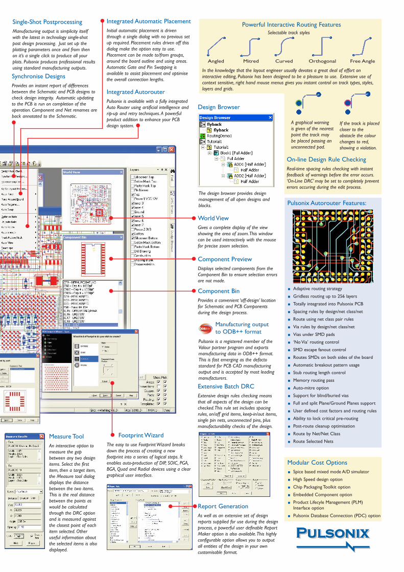
Manufacturing output to ODB++ format
Pulsonix is a registered member of theValour partner program and exportsmanufacturing data in ODB++ format.This is fast emerging as the defactostandard for PCB CAD manufacturingoutput and is accepted by most leadingmanufacturers.
Synchronise DesignsProvides an instant report of differencesbetween the Schematic and PCB designs tocheck design integrity. Automatic updatingto the PCB is run on completion of theoperation. Component and Net renames areback annotated to the Schematic.
Report GenerationAs well as an extensive set of designreports supplied for use during the designprocess, a powerful user definable ReportMaker option is also available.This highlyconfigurable option allows you to outputall entities of the design in your owncustomisable format.
Extensive Batch DRCExtensive design rules checking meansthat all aspects of the design can bechecked.This rule set includes spacingrules, on/off grid items, keep-in/out items,single pin nets, unconnected pins, plusmanufacturability checks of the design.
Design Browser
Component BinProvides a convenient ‘off-design’ locationfor Schematic and PCB Componentsduring the design process.
Footprint Wizard The easy to use Footprint Wizard breaksdown the process of creating a newfootprint into a series of logical steps. Itenables auto-production of DIP, SOIC, PGA,BGA, Quad and Radial devices using a cleargraphical user interface.
On-line Design Rule CheckingReal-time spacing rules checking with instantfeedback of warnings before the error occurs.‘On-Line DRC’ may be set to completely preventerrors occuring during the edit process.
Measure ToolAn interactive option tomeasure the gapbetween any two designitems. Select the firstitem, then a target item,the Measure tool dialogdisplays the distancebetween the two items.This is the real distancebetween the points aswould be calculatedthrough the DRC optionand is measured againstthe closest point of eachitem selected. Otheruseful information aboutthe selected items is alsodisplayed.
If the track is placedcloser to theobstacle the colourchanges to red,showing a violation.
A graphical warning is given of the nearestpoint the track maybe placed passing anunconnected pad.
Adaptive routing strategy
Gridless routing up to 256 layers
Totally integrated into Pulsonix PCB
Spacing rules by design/net class/net
Route using net class pair rules
Via rules by design/net class/net
Vias under SMD pads
‘No Via’ routing control
SMD escape fanout control
Routes SMDs on both sides of the board
Automatic breakout pattern usage
Stub routing length control
Memory routing pass
Auto-mitre option
Support for blind/buried vias
Full and split Plane/Ground Planes support
User defined cost factors and routing rules
Ability to lock critical pre-routing
Post-route cleanup optimisation
Route by Net/Net Class
Route Selected Nets
Powerful Interactive Routing Features
Angled Mitred Curved Orthogonal Free Angle
In the knowledge that the layout engineer usually devotes a great deal of effort oninteractive editing, Pulsonix has been designed to be a pleasure to use. Extensive use ofcontext sensitive, right hand mouse menus gives you instant control on track types, styles,layers and grids.
Selectable track styles
Component PreviewDisplays selected components from theComponent Bin to ensure selection errorsare not made.
Single-Shot PostprocessingManufacturing output is simplicity itselfwith the latest in technology single-shotpost design processing. Just set up theplotting parameters once and from then on it’s a single click to produce all yourplots. Pulsonix produces professional resultsusing standard manufacturing outputs.
Pulsonix Autorouter Features:
Integrated Automatic PlacementInitial automatic placement is driventhrough a single dialog with no previous setup required. Placement rules driven off thisdialog make the option easy to use.Placement can be made to/from groups,around the board outline and using areas.Automatic Gate and Pin Swapping isavailable to assist placement and optimisethe overall connection lengths.
Integrated AutorouterPulsonix is available with a fully integratedAuto Router using artificial intelligence andrip-up and retry techniques. A powerfulproduct addition to enhance your PCBdesign system.
World View Gives a complete display of the viewshowing the area of zoom.This windowcan be used interactively with the mousefor precise zoom selection.
The design browser provides designmanagement of all open designs andblocks.
Modular Cost OptionsSpice based mixed mode A/D simulator
General Features32 bit Windows application Ultra-fast bitmap graphics Supported under Windows 2000/XP & VistaDatabase resolution to 1/100th micron
Object Oriented MosaicTM ArchitectureConnective data structure (not net-list driven)Rotation to 1/100th degreeStandard interface for Schematic/PCBFully integrated design environmentComponent Bin with previewWorld View of designDesign status barCustomisable Toolbars/ShortcutsDockable and Floating ToolbarsTechnology files for fast start-upComprehensive Parts libraryIntegrated library editorsDynamic Pan, Zoom In/outRight mouse shortcut menus Drag and Drop methodology Intelligent copy, paste & duplicate Output to bitmap for documentationUpdate/edit Parts on-the-flyMulti-level Undo and RedoTransient and Persistant GroupsFull and flexible report generationStar/Delta point support for multiple signalsComprehensive item property reportingModal cursorsPowerful Measure toolDesign & Part Assembly VariantsSupport for Windows graphics driver library Floating Network Licensing available Import Schematic, PCB Design and library datafrom many other systems
Schematic CaptureDesign in Imperial or MetricTrue connectivity during all operationsFully customisable interfaceSave and Load Technology filesSymbol creation wizardGraphical symbol and Part editorsSupport for multi-gate logic and irregular devices,such as relaysSave and Load Drawing profilesUses common Parts libraries with PCB editor forsmooth transition from SCM to PCBFlat sheet or Multi-level hierarchySingle or multi-instance of the design blockSupport for FPGA devices built in as standardAutomatic security copy and backup of designsIntelligent Open and Closed BussesReuse of designs using blocks or copy/pasteDynamic drag & drop move, rotate and mirrorParts or groupsDangle Component in mid-air and autoweldfunctionsItem Align functionPredefined and user defined attribute fields forcustom title blocks and auto-updated detailAutomatic/manual Component & Net rename
Electrical Design Rules checking including: presetand user definable rules design integrity rulesOn-line Electrical Rules Checking (ERC)Electrical rules error browserDesign browser showing all sheet levels includinghierarchical blocksNet Class rules definition passed through to PCBdesign editorSave Load Colour filesTruetype fonts support for display and printingCross sheet referencesPower and ground labelsInsert shapesOptimise gatesTestpoint Part and notation insertionForward annotation of changes to the PCBSynchronise design at any time to check designintegrity between SCM and PCB designsBack annotation changes from PCBWindows and pen plotter outputsDXF Import and ExportExport NetlistsUser definable Parts and Netlist outputPredefined drawing profiles supplied
Spice Based A/D Mixed Mode Simulator(optional)
Fully integrated into Pulsonix design environmentUses industry standard modelsPowerful and flexible commerical grade simulator
PCB LayoutDesign area up to 10.0m by 10.0m (393” by 393”)Design in Imperial or Metric Unlimited number of User Defined LayersSupports SMT, through-hole, mixed and slotted-hole technologiesSMDs both sides of the boardBlind and buried via supportSupports embedded component technologyAngles in degrees or radiansIntegrated Schematics & PCBDynamic drag and dropWizards for:Data TransferFootprint creationParts creationPlotting and printingTrack/Via breakouts on footprintsWire jumpers/jumper partsManual Placement ‘push’ and ‘return’ modeIntegrated Autoplace (with Autorouter package)Keep in/out areas use in AutoplacementPlacement areas defined in FootprintOn-line and Batch Design Rules Checking (DRC)On-line Display Clearances Design rules error browserConstruction linesManual Routing angle modes Free angled, 45degree, Orthogonal and CurvedManual Routing modes:Auto Corner, Auto MitreSingle track Auto RouterIntegrated Auto Router (optional)Keep In/Out areas on Autorouting
Support for Teardrops on pads and viasNet Testability and Testpoint AnalysisReverse Engineer, rebuild SCM design from PCBNet Find, Highlight and select browserRelative and Absolute coordinate systemDynamic Net OptimisationMany Report outputs including Parts list & BOMUser definable Report WriterIntegrated Copper Pour with HatchingAutomatic component renameAutomatic Gate and Pin SwappingDynamic DimensioningChange Components on-the-flyDesign CalculatorsGerber Photo-plotter to RS-274-D and RS-274-X (extended aperture format)ODB++ Format exporterAutomatic generation of power plane plotsSupports true split Power PlanesIPC 356 test format outputOutput to GENCam formatWindows printer outputsBuilt-in PDF driver for active PDF filesPlotting to HPGL plottersExcellon NC Drill output and drill drawingsPlotting of solder masks, resist and othermanufacturing plotsIntegrated LPKF Interface DXF Mechanical Design Input/Output IDF Mechanical Design Input/OutputImport Schematic Netlists using: EDIF 2.0.0,OrCAD,Viewdraw, EWB and other vendorsLinks to external autorouters available (Specctra)
High Speed routing (optional)Constraints driven net length managementGraphical length feature and head-up display
Chip-on-board (COB) Design Suite (optional)Die and Bond pad supportIndependently floating bond pads on componentsBond Wire supportInsulated and Cross-over rules for bond wiresMin/Max bond wire length rulesDesign rules checking for COB rulesWire report outputReport maker output of COB entities
Embedded Component Suite (optional)Allows ‘normal’ components to be embeddedonto inner layersContains additional inner layer build dataUsed for embedded and flexi-rigid designsAllows component types for printed resistors/capacitors, planar transformers and spiralinductors
Pulsonix Database Connection (PDC)(optional)
Connect to your corporate database for up-to-date Part information