1-1. Shaft seal (1) Above ground pump (2) Drainage pump ● Gland packing type Gland packing installed Gland packing Photo shows Teflon (white) Mechanical seal Mechanical seal installed ●メカニカルシール Inside of motor: Air Inside the oil chamber: Lubricating oil Inside the casing: Drainage Mechanical seal sliding part (top) Mechanical seal sliding part (bottom) Fig.3 S KSPS LS SM LS SP KH LS2 MKHS LS2 M SP SP3 MSP KSP GV Single-stage direct coupled type Multi-stage direct coupled type Single-stage direct coupled type Multi-stage direct coupled type Single-stage direct coupled type Single-stage direct coupled type Multi-stage direct coupled type Direct coupled type Belt drive type Single-stage motor type Single stage line type Single-stage coupling direct connection type Multi-stage motor type Multi-stage coupling direct connection type Single-stage motor type Single-stage coupling direct connection type Single-stage motor type Single-stage motor type Coupling direct connection type Coupling direct connection type Stainless steel Stainless steel Cast iron Cast iron Cast iron Gear type Self-suction cascade type Resin fabrication Stainless steel Cast iron Gear type Volute pump Single suction volute pump Cascade pump Oil pump Type Model SKJ LP SJ4S SJM3 SJ4 GPM2 SJMS SLP2 SJS NX SVM SJM2 SJ ESPM MTP OKS GPL2 Volute pump Product name: Self-suction type Oil pump Type Model Pump structure Fig.1 Fig.2 Table 1. Representative models Table 2. Representative models In an environment where some leakage is allowed, it is used as a shaft seal for handling fluid. In general, repair and replacement of the shaft seal can be done without disassembling the pump. For this reason, normal maintenance is possible even for beginners of machines. It is used in handling fluids and environments where leakage is not allowed, and in applications where leakage should be eliminated as much as possible. Though the gland packing which is easy to handle was mainly used for pumps for equipment in the past, the mechanical seal has recently become the mainstream due to customers’ advanced needs. Technical data
Transcript
1-1. Shaft seal
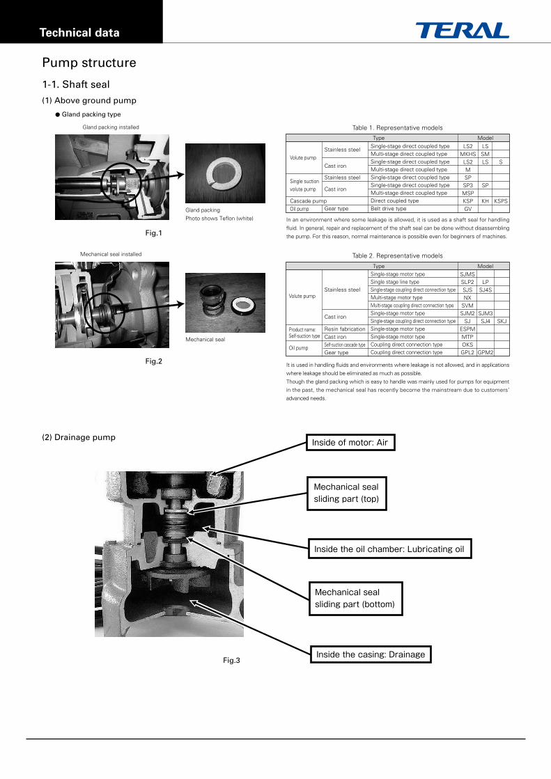
(1) Above ground pump
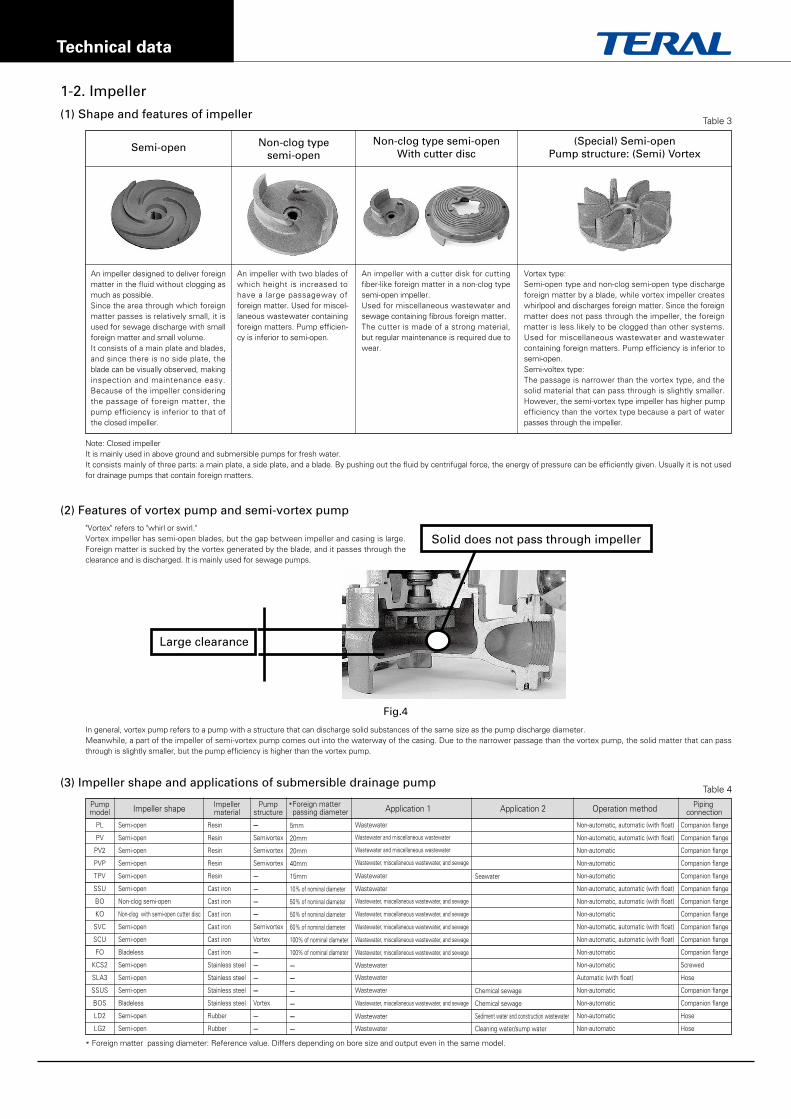
(2) Drainage pump
● Gland packing type
Gland packing installed
Gland packing
Photo shows Teflon (white)
Mechanical seal
Mechanical seal installed
●メカニカルシール
Inside of motor: Air
Inside the oil chamber: Lubricating oil
Inside the casing: Drainage
Mechanical seal sliding part (top)
Mechanical seal sliding part (bottom)
Fig.3
S
KSPS
LSSMLS
SP
KH
LS2MKHS
LS2MSPSP3MSPKSPGV
Single-stage direct coupled typeMulti-stage direct coupled typeSingle-stage direct coupled typeMulti-stage direct coupled typeSingle-stage direct coupled typeSingle-stage direct coupled typeMulti-stage direct coupled typeDirect coupled typeBelt drive type
Single-stage motor typeSingle stage line typeSingle-stage coupling direct connection typeMulti-stage motor typeMulti-stage coupling direct connection typeSingle-stage motor typeSingle-stage coupling direct connection typeSingle-stage motor typeSingle-stage motor typeCoupling direct connection typeCoupling direct connection type
Stainless steel
Stainless steel
Cast iron
Cast iron
Cast iron
Gear typeSelf-suction cascade type
Resin fabrication
Stainless steel
Cast iron
Gear type
Volute pump
Single suction volute pump
Cascade pumpOil pump
Type Model
SKJ
LPSJ4S
SJM3SJ4
GPM2
SJMSSLP2SJSNX
SVMSJM2
SJESPMMTPOKSGPL2
Volute pump
Product name: Self-suction type
Oil pump
Type Model
Pump structure
Fig.1
Fig.2
Table 1. Representative models
Table 2. Representative models
In an environment where some leakage is allowed, it is used as a shaft seal for handling
fluid. In general, repair and replacement of the shaft seal can be done without disassembling
the pump. For this reason, normal maintenance is possible even for beginners of machines.
It is used in handling fluids and environments where leakage is not allowed, and in applications
where leakage should be eliminated as much as possible.
Though the gland packing which is easy to handle was mainly used for pumps for equipment
in the past, the mechanical seal has recently become the mainstream due to customers’
advanced needs.
Technical data
1-2. Impeller
(1) Shape and features of impeller
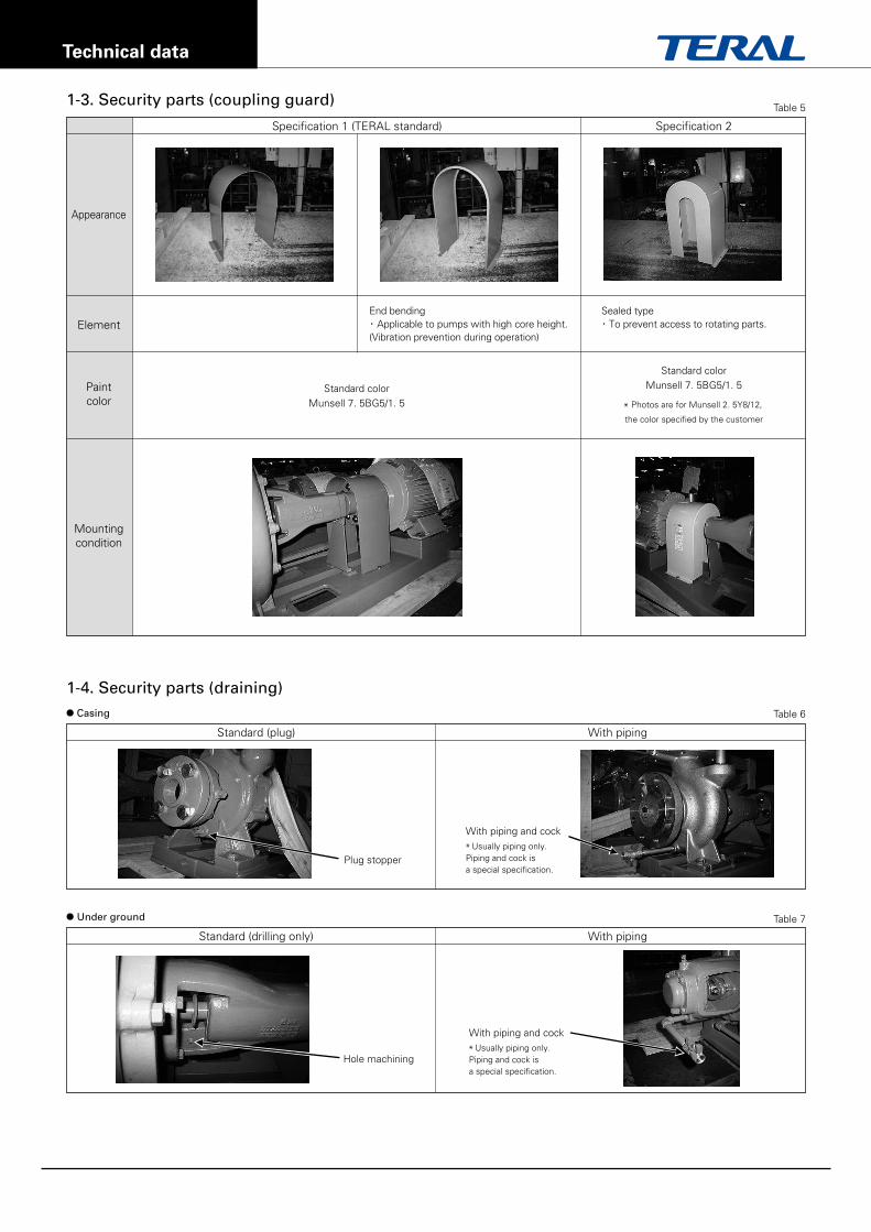
(2) Features of vortex pump and semi-vortex pump
(3) Impeller shape and applications of submersible drainage pump
Semi-open Non-clog typesemi-open
Non-clog type semi-openWith cutter disc
(Special) Semi-openPump structure: (Semi) Vortex
"Vortex" refers to "whirl or swirl."Vortex impeller has semi-open blades, but the gap between impeller and casing is large. Foreign matter is sucked by the vortex generated by the blade, and it passes through the clearance and is discharged. It is mainly used for sewage pumps.
In general, vortex pump refers to a pump with a structure that can discharge solid substances of the same size as the pump discharge diameter.Meanwhile, a part of the impeller of semi-vortex pump comes out into the waterway of the casing. Due to the narrower passage than the vortex pump, the solid matter that can pass through is slightly smaller, but the pump efficiency is higher than the vortex pump.
Note: Closed impellerIt is mainly used in above ground and submersible pumps for fresh water.It consists mainly of three parts: a main plate, a side plate, and a blade. By pushing out the fluid by centrifugal force, the energy of pressure can be efficiently given. Usually it is not used for drainage pumps that contain foreign matters.
Large clearance
Solid does not pass through impeller
Fig.4
Table 3
Table 4
An impeller designed to deliver foreign matter in the fluid without clogging as much as possible.Since the area through which foreign matter passes is relatively small, it is used for sewage discharge with small foreign matter and small volume.It consists of a main plate and blades, and since there is no side plate, the blade can be visually observed, making inspection and maintenance easy. Because of the impeller considering the passage of foreign matter, the pump efficiency is inferior to that of the closed impeller.
An impeller with two blades of which height is increased to have a large passageway of foreign matter. Used for miscel-laneous wastewater containing foreign matters. Pump efficien-cy is inferior to semi-open.
An impeller with a cutter disk for cutting fiber-like foreign matter in a non-clog type semi-open impeller.Used for miscellaneous wastewater and sewage containing fibrous foreign matter.The cutter is made of a strong material, but regular maintenance is required due to wear.
Vortex type:Semi-open type and non-clog semi-open type discharge foreign matter by a blade, while vortex impeller creates whirlpool and discharges foreign matter. Since the foreign matter does not pass through the impeller, the foreign matter is less likely to be clogged than other systems. Used for miscellaneous wastewater and wastewater containing foreign matters. Pump efficiency is inferior to semi-open.Semi-voltex type:The passage is narrower than the vortex type, and the solid material that can pass through is slightly smaller. However, the semi-vortex type impeller has higher pump efficiency than the vortex type because a part of water passes through the impeller.
* Foreign matter passing diameter: Reference value. Differs depending on bore size and output even in the same model.
Technical data
1-4. Security parts (draining)● Casing
Standard (plug)
Plug stopper
With piping and cock
* Usually piping only.Piping and cock isa special specification.
With piping and cock
* Usually piping only.Piping and cock isa special specification.
With piping
● Under ground
Standard (drilling only)
Hole machining
With piping
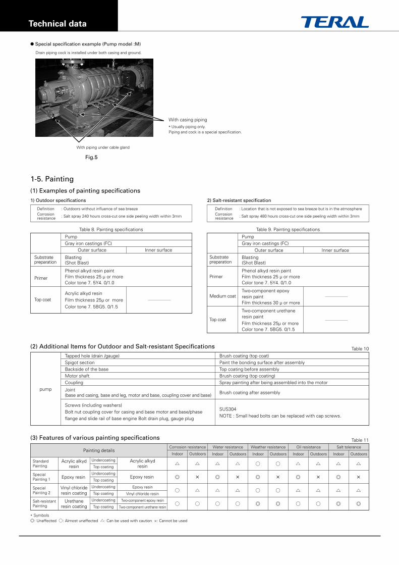
1-3. Security parts (coupling guard)
Standard colorMunsell 7. 5BG5/1. 5
Standard colorMunsell 7. 5BG5/1. 5
* Photos are for Munsell 2. 5Y8/12,
the color specified by the customer
Specification 1 (TERAL standard)
Appearance
Element
Paintcolor
Mountingcondition
Specification 2
Table 5
Table 6
Table 7
End bending・ Applicable to pumps with high core height. (Vibration prevention during operation)
Sealed type・ To prevent access to rotating parts.
Technical data
Table 10
Table 11
pump
Tapped hole (drain /gauge)Spigot sectionBackside of the baseMotor shaftCoupling
Joint(base and casing, base and leg, motor and base, coupling cover and base)
Screws (including washers)Bolt nut coupling cover for casing and base motor and base/phase flange and slide rail of base engine Bolt drain plug, gauge plug
* Symbols◎: Unaffected ○: Almost unaffected △: Can be used with caution ×: Cannot be used
Brush coating (top coat)Paint the bonding surface after assemblyTop coating before assemblyBrush coating (top coating)Spray painting after being assembled into the motor
Brush coating after assembly
SUS304NOTE : Small head bolts can be replaced with cap screws.
Undercoating
Top coating
Undercoating
Top coating
Undercoating
Top coating
Undercoating
Top coating
Acrylic alkydresin
Epoxy resin
Epoxy resin
Vinyl chloride resin
Two-component epoxy resin
Two-component urethane resin
△
◎
○
○
△
×
△
○
△
◎
△
○
△
×
△
○
○
◎
○
◎
○
×
○
◎
△
◎
△
○
△
×
△
○
△
◎
△
◎
△
×
△
◎
Acrylic alkydresin
Epoxy resin
Vinyl chlorideresin coating
Urethaneresin coating
Painting detailsCorrosion resistance
Indoor Outdoors
Water resistance
Indoor Outdoors
Weather resistance
Indoor Outdoors
Oil resistance
Indoor Outdoors
Salt tolerance
Indoor Outdoors
(2) Additional Items for Outdoor and Salt-resistant Specifications
(3) Features of various painting specifications
1-5. Painting
1) Outdoor specifications
Table 8. Painting specifications
Substratepreparation
Primer
Top coat
Substratepreparation
Primer
Medium coat
Top coat
PumpGray iron castings (FC)
Blasting(Shot Blast)
Phenol alkyd resin paintFilm thickness 25 µ or moreColor tone 7. 5Y4. 0/1.0
Acrylic alkyd resin Film thickness 25µ or moreColor tone 7. 5BG5. 0/1.5
Outer surface Inner surface
2) Salt-resistant specification
Table 9. Painting specifications
PumpGray iron castings (FC)
Blasting(Shot Blast)
Phenol alkyd resin paintFilm thickness 25 µ or moreColor tone 7. 5Y4. 0/1.0
Two-component epoxy resin paint Film thickness 30 µ or more
Two-component urethaneresin paint Film thickness 25µ or moreColor tone 7. 5BG5. 0/1.5
Outer surface Inner surface
(1) Examples of painting specifications
● Special specification example (Pump model :M)
With piping under cable gland
Drain piping cock is installed under both casing and ground.
Fig.5
With casing piping
* Usually piping only.Piping and cock is a special specification.
Definition : Outdoors without influence of sea breezeCorrosion : Salt spray 240 hours cross-cut one side peeling width within 3mmresistance
Definition : Location that is not exposed to sea breeze but is in the atmosphereCorrosion : Salt spray 480 hours cross-cut one side peeling width within 3mmresistance
StandardPainting
SpecialPainting 1
SpecialPainting 2
Salt-resistant Painting
Technical data
Fig.6
Fig.7
Fig.8
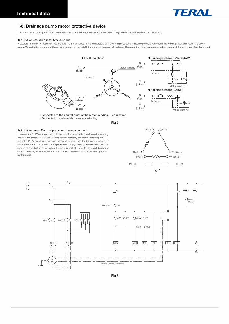
1-6. Drainage pump motor protective device
V(white)
U(Red)
Sub
Motor winding
Protector
● For single-phase (0.4kW)
V(white)
U(Red)
Sub
Motor winding
Protector
● For single-phase (0.15, 0.25kW)● For three-phase
V(white)
U(Red)
Protector
Motor winding
W(Black)
(white) X
(Red) U
(Red) Z
Y (Black)
V (white)
W (Black)
P2P1
RF
TT
X
ResetButton
T
OFF
MCD
MCD MCS
MCM
MCM
Thermal protector lead wire
MCS MCD RT X
OL
T
RT RT
ON
MCM
E
IM3~
U1
V1
W1
V2
W2
U2
MCD MCS
ST
The motor has a built-in protector to prevent burnout when the motor temperature rises abnormally due to overload, restraint, or phase loss.
1) 7.5kW or less: Auto-reset type auto-cutProtectors for motors of 7.5kW or less are built into the windings. If the temperature of the winding rises abnormally, the protector will cut off the winding circuit and cut off the power
supply. When the temperature of the winding drops after the cutoff, the protector automatically returns. Therefore, the motor is protected independently of the control panel on the ground.
2) 11 kW or more: Thermal protector (b-contact output)For motors of 11 kW or more, the protector is built in a separate circuit from the winding
circuit. If the temperature of the winding rises abnormally, the circuit containing the
protector (P1-P2 circuit) is cut off, and the circuit returns when the temperature drops. To
protect the motor, the ground control panel must supply power when the P1-P2 circuit is
connected and shut off power when the circuit is shut off. Refer to the circuit diagram of
control panel (Fig.8). This allows the motor to be protected by a protector and a ground
control panel.
* Connected to the neutral point of the motor winding ( λ connection)* Connected in series with the motor winding
Main
Main
Technical data
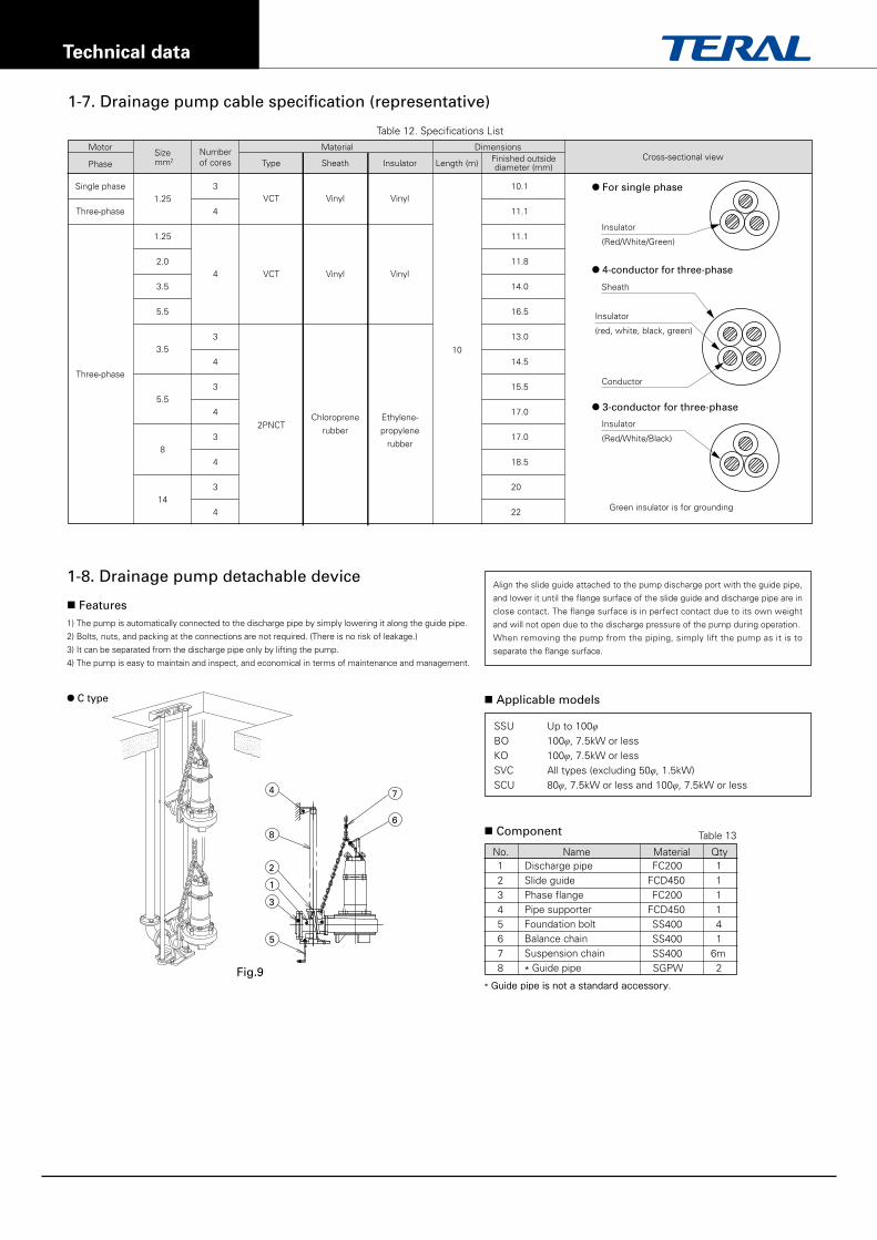
1-8. Drainage pump detachable device
Table 13
Fig.9
Align the slide guide attached to the pump discharge port with the guide pipe,
and lower it until the flange surface of the slide guide and discharge pipe are in
close contact. The flange surface is in perfect contact due to its own weight
and will not open due to the discharge pressure of the pump during operation.
When removing the pump from the piping, simply lift the pump as it is to
PL All typesPV All typesBO 65φ/80φ/100φ, 11kW or more, and 125φ or moreKO 65φ/80φ, 11kW or moreSVC (50φ, 1.5kW only)SCU 80φ, 11kW or more, and 100φ,11kW or more
NOTE) 1. *1 Nominal Dia. shows piping diameters. 2. *2 In case of changing side discharge to upper discharge, discharge bend (flange: JIS10K equivalent type) is available as a special accessory. 3. *3 The diameter is 65 for 7.5kW or more of BO,KO pump and SVC pump. 4. *4 The nominal dia. is obtained with the companion flange.
Operation control panel Required Not required Not required
Appearance
Used for spring water tanks and small water tanks. Used as a set of 2 units in a large water tank.
For non-automatic pumps, one or two pumps are actually combined with a control panel, float switch, etc. to perform automatic operation based on
the water level. The control panel may be provided by TERAL (BD3L type or BD3S type) or may be arranged at the site including electrical work.
How to use
1. When two pumps, type A and type T, are used together, automatic alternate parallel operation can be performed with the float switch supplied with the pump without using the control panel.
2. The power supply capacity is required for two pumps.
3. Required wiring is just connecting the pump to the power supply. Be sure to also connect the ground wire.
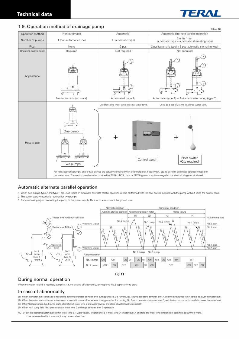
During normal operation
In case of abnormality
When the water level B is reached, pump No.1 turns on and off alternately, giving pump No.2 opportunity to start.
(1) When the water level continues to rise due to abnormal increase of water level during pump No.2 is running, No.1 pump also starts at water level A, and the two pumps run in parallel to lower the water level.
(2) When the water level continues to rise due to abnormal increase of water level during pump No.1 is running, No.2 pump also starts at water level D, and the two pumps run in parallel to lower the water level.
(3) WhenNo.2 pump fails, No.1 pump starts alternately at water level B and water level A, and stops at water level C repeatedly.
(4) When No.1 pump fails, No.2 pump starts at water level D and stops at water level E repeatedly.
Water level A (abnormal start) No.1 abnormal start
Water level B(Start) No.1 start
Water level D (start)
Normal operation Abnormal condition
Automatic alternate operation Abnormal increase in water Pump failure
No.2 start
Water level E (Stop) No.2 stopWater level C
(Stop)No.1 stop
No.1pump(type TParent
No.2pump
(type A)Child No.1 pump ON ON ON ON ON ONOFF OFF OFF OFF OFF OFF
No.2 pump OFF OFF OFF OFF OFFON ON ON ON ON
Pump operationNo.2 pump No.2 pump
No.2 failure No.1 failure
Automatic alternate parallel operation
(1) (2) (3) (4)
NOTE) Set the operating water level so that water level E < water level C < water level B < water level D < water level A, and take the water level difference of each float to 50mm or more.
If the set water level is not normal, it may cause malfunction.