16
1 January 2013 • heavy duty • low odour • fire rated • pure epoxy anchoring adhesive • low VOC content Edition: January 2013 [ Previously marketed as “PF PRO” ]
| Date post: | 22-Jul-2016 |
| Category: |
Documents |
| Upload: | sayed-diab-alsayed |
| View: | 4 times |
| Download: | 1 times |

1January 2013
• heavy duty • low odour • fire rated• pure epoxy anchoring adhesive
• low VOC content
Edition: January 2013
[ Previously marketed as “PF PRO” ]

2January 2013
Powers offers the widest range of mechanical and adhesive fasteners in the market place.Powers products cover the full traditional anchoring range while specialising in innovative products that provide the architect, engineer and end user with aesthetic, high performance, labour saving fastening solutions.
For fast technical advice, free samples and free on site demonstrations,visit our website www.powers.com.au
Other Powers adhesive systems
KF2
Economical
Easy to apply
AC100e
Standard caulking gun
Easy to apply
Environmentally friendly
AC100® PRO
High performance.
Fast curing
Styrene free
National On Site
Service
Powers Training
Vehicles (PTV)
National on Site
Anchor Testing
Service
In-house Product &
Application Testing
Service
Melbourne
Support
In House Product
Training Facility
Melbourne
V12
High performance
Economical
Versatile
Vinyl ester resin
PURE150-PRO
3January 2013
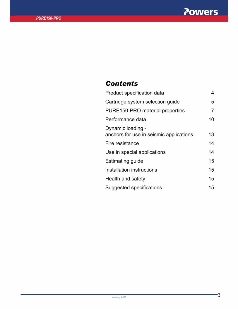
Contents
Cartridge system selection guide 5
PURE150-PRO material properties 7
Performance data 10
Dynamic loading -
anchors for use in seismic applications 13
Estimating guide 15
Installation instructions 15
Health and safety 15
PURE150-PRO

4January 2013
PURE150-PRO epoxy injection adhesive is a new and improved two component structural epoxy packaged in a specially designed cartridge. The cartridge is made from an engineered plastic and is used with either a manual or pneumatically operated injection tool. The new epoxy is a low odour, premium, high strength pure epoxy, which contains low levels of volatile organic compounds (VOCs) and has a proven track record. The mixed adhesive is now a red colour, for easy inspection on site.PURE150-PRO has longer gel/working time and easier handling (extrudes better) when compared to Power-Fast®PLUS. PURE150-PRO epoxy injection adhesive is designed for use in anchoring threaded rod, bolts, and reinforcing bars into concrete
In addition to anchoring applications, PURE150-PRO epoxy injection adhesive can be used for bonding steel and cured concrete to cured concrete. It can also be used
PURE150-PRO
Introduction
PURE150-PRO Cartridge
The design of the PURE150-PRO cartridge eliminates the leakage and dispensing problems often found with other systems. Supplied in a 385ml or 585ml capacity, each
One tube contains the Component A - Base Resin while the other tube contains the Component B - Hardener. The tubes are separated to keep the components out of contact until they are ready to be dispensed. Each cartridge is formed from an engineered plastic using a special high tolerance molding process. At the front end of each cartridge is a reinforced retention cap and a threaded manifold. A set of plastic pushers is inserted into the rear of each tube to pressurise the epoxy during dispensing. This provides the user with a cartridge which is easy to dispense, yet durable.
Product specification data
PURE150-PRO Mixing nozzles
To ensure complete and proper mixing of the epoxy components, the PURE150-PRO system use a static mixing nozzle. This reduces the possibility of mixing errors which are common with hand mixed pourable grout materials. The mixing nozzles have been designed with a unique tapered extension tip that allows for easy assembly of the extension nozzle. The assembled nozzle system can be used to inject epoxy into most anchor hole sizes. Each nozzle contains a series of stationary components
position as the epoxy components are pumped through the nozzle. As the components are pumped through the nozzle, they are progressively divided and recombined by the stationary mixing elements to ensure precise automatic mixing of the components.
PURE150-PRO
PART NO DESCRIPTION QUANTITY
PFPN Mixing nozzle for PF PRO, includes extension nozzle 10

5January 2013
PURE150-PRO
PURE150-PRO Cartridge
PART NO DESCRIPTION QUANTITY
PURE150PRO-385 385ml Cartridge + 2 mixing nozzles 1
PURE150PRO-585 585ml Cartridge + 2 mixing nozzles 1
Threaded Rod (STMTM studs)
Powers Fasteners supplies a range of adhesive anchor studs (STMTM) for use based on standard embedment depth applications. For alternate embedment depths, studs
Powers Fasteners must be from a reputable source and material properties should
Powers Fasteners supplies studs in stainless steel, galvanised steel and zinc plated steel, environmental factors and application factors should be considered carefully prior to selecting the correct stud.
STMTM – Chisel Point Stud 5.8
Carbon Steel Yellow Passivated
PART NO. DESCRIPTION mm mm mm QTY QTY
STM8110 8 x 110 with Nut and Washer 10 80 17 10 200
STM10130 10 x 130 with Nut and Washer 12 90 28 10 200
STM12160 12 x 160 with Nut and Washer 14 110 36 10 100
STM16190 16 x 190 with Nut and Washer 18 125 42 10 50
STM20260 20 x 260 with Nut and Washer 24 170 72 5 25
STM24300 24 x 300 with Nut and Washer 28 210 66 5 20
STMTM – Chisel Point Stud Galvanised Class 5.8
Carbon Steel Galvanised
PART NO. DESCRIPTION mm mm mm QTY QTY
STM8110G 8 x 110 with Nut and Washer 10 80 17 10 200
STM10130G 10 x 130 with Nut and Washer 12 90 28 10 200
STM12160G 12 x 160 with Nut and Washer 14 110 36 10 100
STM16190G 16 x 190 with Nut and Washer 18 125 42 10 50
STM20260G 20 x 260 with Nut and Washer 24 170 72 5 25
STM24300G 24 x 300 with Nut and Washer 28 210 66 5 20
Cartridge system selection guide

6January 2013
PURE150-PRO
STMTM – Chisel Point Stud 316 Stainless Steel
316 Stainless Steel
PART NO. DESCRIPTION mm mm mm QTY QTY
STM8110SS 8 x 110 with Nut and Washer 10 80 17 10 200
STM10130SS 10 x 130 with Nut and Washer 12 90 28 10 200
STM12160SS 12 x 160 with Nut and Washer 14 110 36 10 100
STM16190SS 16 x 190 with Nut and Washer 18 125 42 10 50
STM20260SS 20 x 260 with Nut and Washer 24 170 72 5 25
STM24300SS 24 x 300 with Nut and Washer 28 210 66 5 20
Manual injection tools
The CG 585 manual injection tool is designed with a pump style drive mechanism which has a high pump ratio to provide fast dispensing. The base unit and the handle assembly is manufactured from a precision steel casting for long life. A specially designed wear compensation mechanism ensures consistent pumping over the life of the tool. The tool is designed for use with the 385ml and 585ml cartridge only.
mechanism which has a high pump ratio to provide fast dispensing. The base unit is a unique design which allows for the dispensing of different cartridge sizes consisting
PART NO DESCRIPTION QTY
CG585 Dispensing gun for 385ml and 585ml cartridge 1
CGPRO-4 Dispensing gun for all Powers adhesives 1
Pneumatic injection tool
The pneumatic injection tool is designed for large jobs. The main cylinder is formed using top quality aluminum to provide a lightweight, durable tool. The dispensing trigger is designed to provide instant pressure relief from the cartridge which reduces waste.
PART NO DESCRIPTION QUANTITY
CGPN585 Pneumatic Dispensing gun for 385ml and 585ml cartridge 1
Maximum Operating Pressure - 110 psi
Normal Operating Range - 80 to 100 psi
Maximum Free Air Required - 1 CFM based on average use
CG585
CGPRO-4
7January 2013
PURE150-PRO material properties
PURE150-PRO
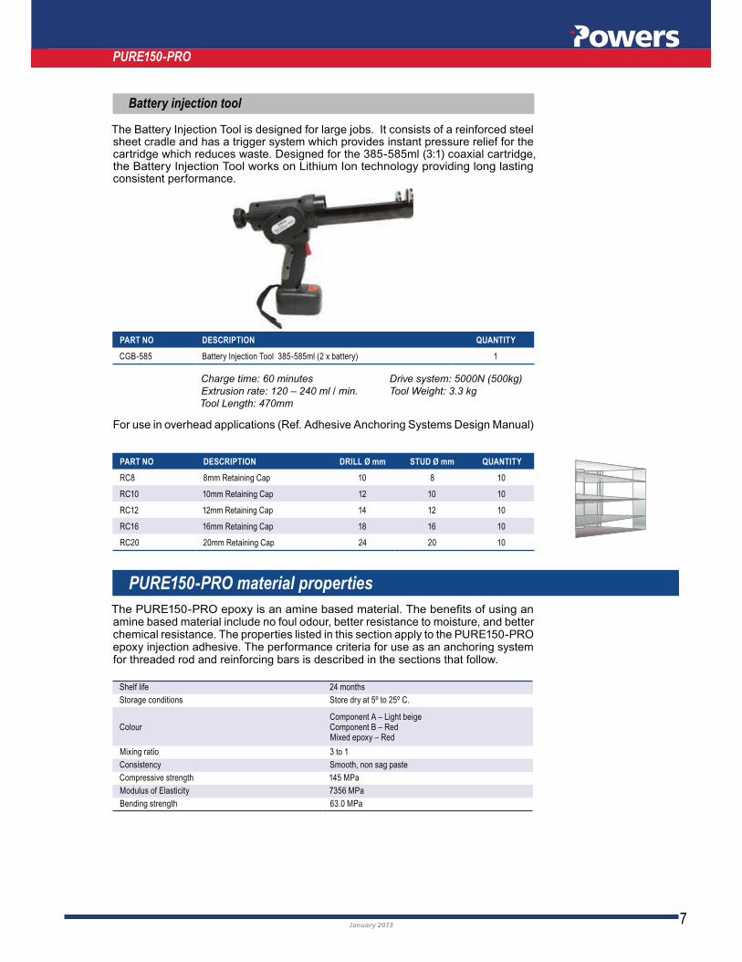
Battery injection tool
The Battery Injection Tool is designed for large jobs. It consists of a reinforced steel sheet cradle and has a trigger system which provides instant pressure relief for the
the Battery Injection Tool works on Lithium Ion technology providing long lasting consistent performance.
Charge time: 60 minutes Drive system: 5000N (500kg)
Extrusion rate: 120 – 240 ml / min. Tool Weight: 3.3 kg
Tool Length: 470mm
PART NO DESCRIPTION QUANTITY
CGB-585 Battery Injection Tool 385-585ml (2 x battery) 1
For use in overhead applications (Ref. Adhesive Anchoring Systems Design Manual)
PART NO DESCRIPTION DRILL Ø mm STUD Ø mm QUANTITY
RC8 8mm Retaining Cap 10 8 10
RC10 10mm Retaining Cap 12 10 10
RC12 12mm Retaining Cap 14 12 10
RC16 16mm Retaining Cap 18 16 10
RC20 20mm Retaining Cap 24 20 10
amine based material include no foul odour, better resistance to moisture, and better chemical resistance. The properties listed in this section apply to the PURE150-PRO epoxy injection adhesive. The performance criteria for use as an anchoring system for threaded rod and reinforcing bars is described in the sections that follow.
Shelf life 24 months
Storage conditions Store dry at 5º to 25º C.
ColourComponent A – Light beigeComponent B – RedMixed epoxy – Red
Mixing ratio 3 to 1
Consistency Smooth, non sag paste
Compressive strength 145 MPa
Modulus of Elasticity 7356 MPa
Bending strength 63.0 MPa

8January 2013
PURE150-PRO Epoxy injection gel setting time
The setting times listed for the PURE150-PRO epoxy vary according to the volume of epoxy used and the base material temperature. The working time is the maximum time during which the epoxy can be dispensed before it begins to set. The full curing time is the minimum time required for the epoxy to reach its published physical properties.
BASE MATERIALTEMP. ( C)
MAXIMUM WORKING TIME(MINUTES)
FULL CURING TIME(HOURS)
0 180 50
10 120 24
20 30 10
30 20 6
40 12 4
PURE150-PRO Quality control procedures
PURE150-PRO epoxy injection adhesive is packaged individually. Each cartridge contains a manufacture date which provides traceability of the components back to the original manufacturing batch. Every batch of material is subjected to extensive physical and chemical property testing during manufacture. Each combination of base resin and hardener material batches is tested as an installed anchor to ensure that the proper bond strength is developed. These procedures ensure consistent, top quality performance
VOC Content certification
Powers PURE150-PRO Injection System has been tested in accordance with SCAQMD
materials as referenced by South Coast Air Quality Management Division (SCAQMD) Rule 1168.The VOC content of Powers PURE150-PRO has been determined and the product
NOTE: For wet concrete curing times must be doubled
PURE150-PRO
9January 2013
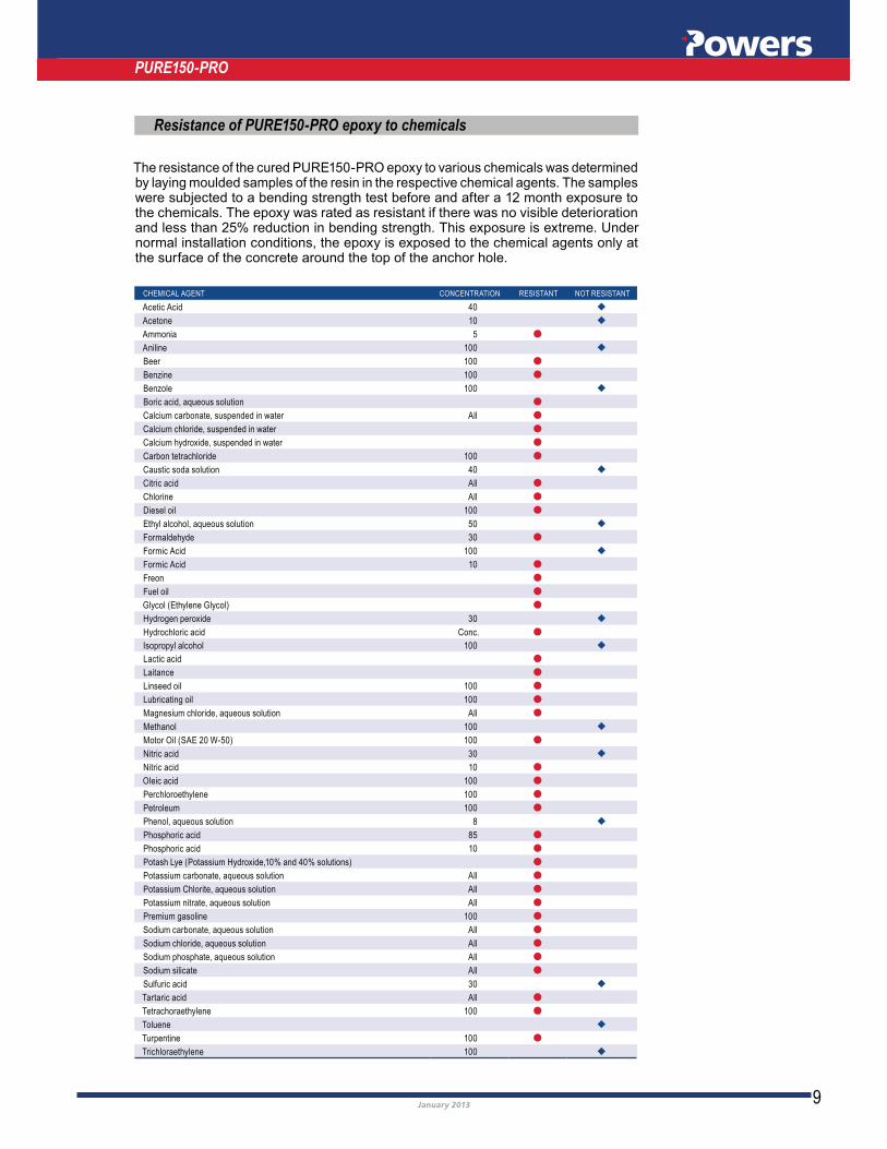
Resistance of PURE150-PRO epoxy to chemicals
The resistance of the cured PURE150-PRO epoxy to various chemicals was determined by laying moulded samples of the resin in the respective chemical agents. The samples were subjected to a bending strength test before and after a 12 month exposure to the chemicals. The epoxy was rated as resistant if there was no visible deterioration and less than 25% reduction in bending strength. This exposure is extreme. Under normal installation conditions, the epoxy is exposed to the chemical agents only at the surface of the concrete around the top of the anchor hole.
CHEMICAL AGENT CONCENTRATION RESISTANT NOT RESISTANT
Acetic Acid 40 ◆
Acetone 10 ◆
Ammonia 5 ●
Aniline 100 ◆
Beer 100 ●
Benzine 100 ●
Benzole 100 ◆
Boric acid, aqueous solution ●
Calcium carbonate, suspended in water All ●
Calcium chloride, suspended in water ●
Calcium hydroxide, suspended in water ●
Carbon tetrachloride 100 ●
Caustic soda solution 40 ◆
Citric acid All ●
Chlorine All ●
Diesel oil 100 ●
Ethyl alcohol, aqueous solution 50 ◆
Formaldehyde 30 ●
Formic Acid 100 ◆
Formic Acid 10 ●
Freon ●
Fuel oil ●
Glycol (Ethylene Glycol) ●
Hydrogen peroxide 30 ◆
Hydrochloric acid Conc. ●
Isopropyl alcohol 100 ◆
Lactic acid ●
Laitance ●
Linseed oil 100 ●
Lubricating oil 100 ●
Magnesium chloride, aqueous solution All ●
Methanol 100 ◆
Motor Oil (SAE 20 W-50) 100 ●
Nitric acid 30 ◆
Nitric acid 10 ●
Oleic acid 100 ●
Perchloroethylene 100 ●
Petroleum 100 ●
Phenol, aqueous solution 8 ◆
Phosphoric acid 85 ●
Phosphoric acid 10 ●
Potash Lye (Potassium Hydroxide,10% and 40% solutions) ●
Potassium carbonate, aqueous solution All ●
Potassium Chlorite, aqueous solution All ●
Potassium nitrate, aqueous solution All ●
Premium gasoline 100 ●
Sodium carbonate, aqueous solution All ●
Sodium chloride, aqueous solution All ●
Sodium phosphate, aqueous solution All ●
Sodium silicate All ●
Sulfuric acid 30 ◆
Tartaric acid All ●
Tetrachoraethylene 100 ●
Toluene ◆
Turpentine 100 ●
Trichloraethylene 100 ◆
PURE150-PRO

10January 2013
PURE150-PRO
Performance data
Working stress design
Allowable working loads are based on the lesser of the allowable bond strength and allowable steel strength.
ALLOWABLE BOND STRENGTHCONCRETE – TENSION
ALLOWABLE STEEL STRENGTH(min)
ANCHOR SIZEmm
DRILLSIZEmm
EMBED.DEPTH
mm
TORQUERANGE
Nm
15MPa
kN
32MPa
kN
40MPa
kN
TENSIONkN
Class 5.8
TENSIONkN
Class 8.8
TENSIONkN
316 S/S(A4-50)
M8 10 10 7.6 11.7 8.140 3.6 5.1 6.5
60 5.7 7.7 9.6
80 7.9 9.5 12.2
M10 12
40
20
4.4 6.4 7.4
12.1 18.6 12.860 6.6 9.9 11.5
90 11.1 13.9 17.1
115 13.7 16.6 20.1
M12 14
50
40
6.8 10.6 11.6
17.5 27.0 18.675 10.9 15.4 17.8
110 16.0 22.7 25.9
150 21.8 28.9 34.2
M16 18
65
80
11.4 13.3 17.2
32.7 50.0 34.595 17.0 22.8 26.4
125 23.1 32.1 37.1
190 35.5 46.5 56.8
M20 24
75
120
13.2 15.2 18.5
51.0 81.2 53.9115 23.8 26.8 35.1
170 38.6 54.6 59.7
230 52.4 65.3 76.6
M24 28
100
160
27.4 34.1 41.4
73.4 117.2 77.9150 40.9 51.4 56.8
210 56.3 77.4 88.5
300 87.3 118.4 136.5
M30 35
125
180
37.0 52.3 60.4
116.7 186.4 123.4190 56.0 79.6 91.9
270 79.9 113.1 130.6
380 123.8 175.2 202.4
M36 40
140
200
47.3 67.0 77.4
169.9 271.2 179.7210 71.0 100.6 116.0
330 112.6 159.6 184.3
420 150.0 212.2 245.0
ALLOWABLE BOND STRENGTHCONCRETE – SHEAR
ALLOWABLE STEEL STRENGTH(min)
ANCHOR SIZEmm
DRILLSIZEmm
EMBED.DEPTH
mm
TORQUERANGE
Nm
15MPa
kN
32MPa
kN
40MPa
kN
SHEARkN
Class 5.8
SHEARkN
Class 8.8
SHEARkN
316 S/S(A4-50)
M8 10 40 10 5.6 4.2 6.5 5.0
M10 12 40 20 7.7 6.7 10.4 7.9
M12 14 50 40 13.2 9.8 15.1 11.5
M16 18 65 80 20.9 18.6 28.6 21.4
M20 24 75 120 34.7 29.0 46.3 33.4
M24 28 100 160 63.0 41.8 66.7 48.3
M30 35 125 180 99.7 66.9 115.5 76.5
M36 40 140 200 116.5 97.9 168.2 111.4
Tension
Incorporated Safety Factors(Tension and shear):Allowable bond strength(concrete)f
sc=3
Allowable steel strength fss
=2.5
Incorporated Safety Factors(Tension and shear):Allowable bond strength(concrete)f
sc=3
Allowable steel strength fss
=2.5
Shear
NOTE:The allowable Working Loadused should be the lesser of the bond or steel strength.
Spacing and
Edge Distance
For anchor spacing, edge distance and combined loading information,
edge distance Rs e(t & s)
11January 2013
PURE150-PRO
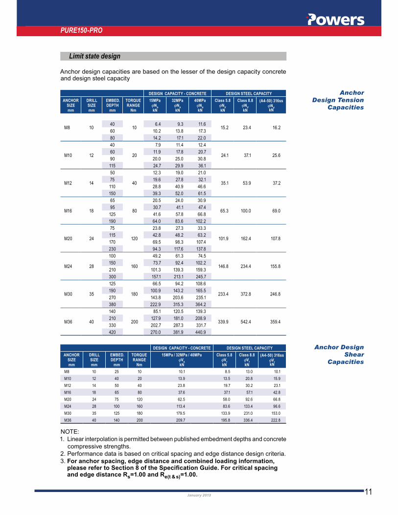
Limit state design
DESIGN CAPACITY - CONCRETE DESIGN STEEL CAPACITY
ANCHOR SIZEmm
DRILLSIZEmm
EMBED.DEPTH
mm
TORQUERANGE
Nm
15MPaφN
A
kN
32MPaφN
A
kN
40MPaφN
A
kN
Class 5.8φN
tf
kN
Class 8.8φN
tf
kN
(A4-50) 316ssφN
tfkN
M8 10 10 15.2 23.4 16.240 6.4 9.3 11.6
60 10.2 13.8 17.3
80 14.2 17.1 22.0
M10 12
40
20
7.9 11.4 12.4
24.1 37.1 25.660 11.9 17.8 20.7
90 20.0 25.0 30.8
115 24.7 29.9 36.1
M12 14
50
40
12.3 19.0 21.0
35.1 53.9 37.275 19.6 27.8 32.1
110 28.8 40.9 46.6
150 39.3 52.0 61.5
M16 18
65
80
20.5 24.0 30.9
65.3 100.0 69.095 30.7 41.1 47.4
125 41.6 57.8 66.8
190 64.0 83.6 102.2
M20 24
75
120
23.8 27.3 33.3
101.9 162.4 107.8115 42.8 48.2 63.2
170 69.5 98.3 107.4
230 94.3 117.6 137.8
M24 28
100
160
49.2 61.3 74.5
146.8 234.4 155.8150 73.7 92.4 102.2
210 101.3 139.3 159.3
300 157.1 213.1 245.7
M30 35
125
180
66.5 94.2 108.6
233.4 372.8 246.8190 100.9 143.2 165.5
270 143.8 203.6 235.1
380 222.9 315.3 364.2
M36 40
140
200
85.1 120.5 139.3
339.9 542.4 359.4210 127.9 181.0 208.9
330 202.7 287.3 331.7
420 270.0 381.9 440.9
DESIGN CAPACITY - CONCRETE DESIGN STEEL CAPACITY
ANCHOR SIZEmm
DRILLSIZEmm
EMBED.DEPTH
mm
TORQUERANGE
Nm
15MPa / 32MPa / 40MPaφV
A
kN
Class 5.8φV
f
kN
Class 8.8φV
f
kN
(A4-50) 316ssφV
fkN
M8 10 25 10 10.1 8.5 13.0 10.1
M10 12 40 20 13.9 13.5 20.8 15.9
M12 14 50 40 23.8 19.7 30.2 23.1
M16 18 65 80 37.6 37.1 57.1 42.8
M20 24 75 120 62.5 58.0 92.6 66.8
M24 28 100 160 113.4 83.6 133.4 96.6
M30 35 125 180 179.5 133.9 231.0 153.0
M36 40 140 200 209.7 195.8 336.4 222.8
Anchor
Design Tension
Capacities
Anchor Design
Shear
Capacities
Anchor design capacities are based on the lesser of the design capacity concrete and design steel capacity
1. Linear interpolation is permitted between published embedment depths and concrete
compressive strengths.
2. Performance data is based on critical spacing and edge distance design criteria.
3. For anchor spacing, edge distance and combined loading information,
and edge distance Rs e(t & s)

12January 2013
PURE150-PRO
Design for strength limit state
Reinforcing bar limit state design data
Design is based on the lesser of the concrete and steel capacities.
N* ≤ φNA,tf
Tension
V* ≤ φVA,f
Shear
(N*/φNA,tf
)5/3 + (V* / φVA,f
)5/3 ≤ 1 Combined loading
N* = Design tension force (kN)
V* = Design shear force (kN)
φNA,tf
= Anchor design tension capacity (kN)
φVAf
= Anchor design shear capacity (kN)
NA = Characteristic ultimate tension load capacity (kN)
VA = Characteristic ultimate shear load capacity (kN)
φ = 0.6 [Strength reduction factor]– tension and shear
Ntf = Nominal tension capacity of steel (kN)
Vf = Nominal shear capacity of steel (kN)
φ = 0.8 [Capacity factor – tension and shear]
BAR Ø
mm
DRILLØ
mmANCHOR DESIGN TENSION CAPACITIES (CONCRETE / BOND) (φN
A)
BAR DEVELOPMENT STRENGTH (kN)
(Fsy
)
DEVELOPMENTLENGTH
Lsy,t
N10 12 24.6 30.8 36.9 46.0 39.3 128
N12 15 30.8 38.5 46.1 57.6 69.1 56.5 147
N16 20 51.3 57.7 72.1 86.5 100.5 114.9 100.5 210
N20 25 58.1 69.7 87.1 104.5 122.0 139.4 157.0 174.3 157.0 270
N24 30 86.5 108.2 129.8 151.4 173.0 194.7 216.3 251.4 226.0 314
N28 35 100.9 126.2 151.4 176.6 201.9 227.1 252.4 294.4 335.2 308.0 366
N32 40 139.4 167.3 195.2 223.0 250.9 278.8 325.3 371.7 463.7 402.0 433
N36 44 149.1 178.9 208.7 238.6 268.4 298.2 347.9 397.6 497.0 596.7 510.0 513
N40 50 249.9 281.2 312.4 364.5 416.6 520.7 628.5 733.0 630.0 605
INSTALLED LENGTHL
inst
80 100 120 150 180 210 240 270 300 350 400 500 600 700 mm
1 Anchor Design Tension Capacities φ NA incorporate a strength reduction
factor φ
2 ƒ′c=32MPa minimum (For ƒ′
c > 32 MPa assume C
f=1.0, where C
f=Compressive
Strength Factor
3 Capacities based on Grade 500N rebar, in accordance with
of 8 x d and edge distance (tension) of 6 x d. Where d = Bar Diameter.
5 Base Material Thickness (BMT) must be minimum 150% of anchor embedment
when rebars are utilised as anchors. For reinforcing applications, the requirements
Development Length and Splicing of Reinforcement for Stress Development
applications, LHS of equation 13.1.2.2 (with k1 = 1, for post-installed bars) and
13January 2013
development length. The greater of the development length as per AS3600-
for design purposes to satisfy the code/standard requirements.
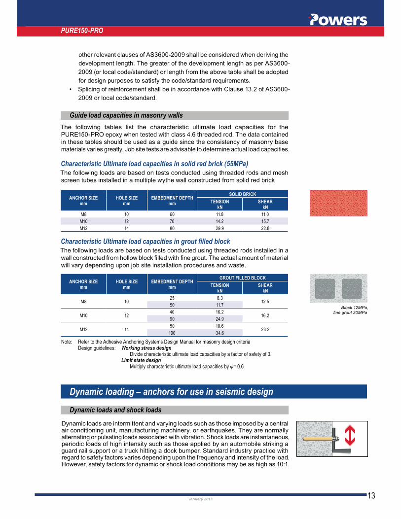
Block 12MPa,fine grout 20MPa
PURE150-PRO
Guide load capacities in masonry walls
The following tables list the characteristic ultimate load capacities for the
in these tables should be used as a guide since the consistency of masonry base
materials varies greatly. Job site tests are advisable to determine actual load capacities.
Characteristic Ultimate load capacities in solid red brick (55MPa) The following loads are based on tests conducted using threaded rods and mesh
screen tubes installed in a multiple wythe wall constructed from solid red brick
ANCHOR SIZEmm
HOLE SIZEmm
EMBEDMENT DEPTHmm
SOLID BRICK
TENSION kN
SHEARkN
M8 10 60 11.8 11.0
M10 12 70 14.2 15.7
M12 14 80 29.9 22.8
Characteristic Ultimate load capacities in grout filled block The following loads are based on tests conducted using threaded rods installed in a
will vary depending upon job site installation procedures and waste.
ANCHOR SIZEmm
HOLE SIZEmm
EMBEDMENT DEPTHmm
GROUT FILLED BLOCK
TENSION kN
SHEARkN
M8 1025 8.3
12.550 11.7
M10 1240 16.2
16.290 24.9
M12 1450 18.6
23.2100 34.6
Note: Refer to the Adhesive Anchoring Systems Design Manual for masonry design criteria Design guidelines: Working stress design Divide characteristic ultimate load capacities by a factor of safety of 3. Limit state design Multiply characteristic ultimate load capacities by φ= 0.6.
Dynamic loading – anchors for use in seismic design
Dynamic loads and shock loads
Dynamic loads are intermittent and varying loads such as those imposed by a central air conditioning unit, manufacturing machinery, or earthquakes. They are normally alternating or pulsating loads associated with vibration. Shock loads are instantaneous, periodic loads of high intensity such as those applied by an automobile striking a guard rail support or a truck hitting a dock bumper. Standard industry practice with regard to safety factors varies depending upon the frequency and intensity of the load.

14January 2013
PURE150-PRO
Diamond cored holes
Some adhesive systems experience a considerable reduction in performance due to shrinkage during curing thus making them unsuitable for installation in diamond core-drilled holes. The PURE150-PRO epoxy injection system does not experience any shrinkage during curing and performs equally well in both rotary hammer-drilled and diamond core-drilled holes.
Drinking water system components certification
for use in contact with drinking water.).
Earthquake loads) should be conducted by a design professional. Powers Fasteners have tested various epoxy injection systems under seismic conditions as outlined in
Installed Adhesive Anchors in Concrete Elements. Procedure outline of seismic testing, including results, available upon request.
Anchors for use in seismic design
Designation Powers PURE150-PRO
Fire resistance timet
u
(minutes)
Maximum tensile load*F
(kN)
M8 M10 M12 M16 M20 M24 M27 M30
Minimum set depth(mm)
80 90 110 125 170 210 250 280
30 0.90 3.20 4.20 8.25 17.25 24.85 32.30 39.50
60 0.50 1.80 2.30 5.30 10.20 14.75 19.15 23.40
90 0.30 1.10 1.40 3.80 6.70 9.70 12.60 15.40
120 0.20 0.75 0.90 3.00 5.00 7.20 9.30 11.35
Fire resistance of PURE150-PRO injection system in combination with anchor rods of sizes M8 to M30 in CLASS 5.8 galvanised steel. Fire resistance relates to maximum allowable tension loads for various durations of time in solid reinforced concrete of minimum strength 25MPa.
NOTE: For report details please contact Powers Fasteners Technical Department
Fire resistance
Use in special applications
Installation of anchors under water
PURE150-PRO epoxy injection adhesive can be used for the installation of threaded anchor rod or reinforcing bars in submerged applications under water provided some installation and design criteria are followed. The anchor holes should be prepared following the standard installation instructions with the following exceptions.
Special care should be taken to clean the anchor hole as a slurry of concrete paste tends to form on the walls of the anchor hole when drilling under water. To inject the epoxy, insert the mixing nozzle to the bottom or rear of the anchor hole. Slowly
completely with epoxy prior to inserting the anchor rod.

15January 2013
The setting time of the PURE150-PRO epoxy in submerged applications depends upon the base material temperature as listed in the material properties section.
the ultimate tension load capacity can be expected for an anchor which is installed under water. The design professional should include this reduction in their calculations.
PURE150-PRO
Adhesive anchor functioning for removability
Many temporary anchoring applications which require high load capacities, also need to be removable. Adhesive systems often provide the highest load capacities, but have not been easily removable. When using the PURE150-PRO epoxy injection adhesive, Powers has developed a method that has several advantages over those offered by competitive systems. Typically, a removable installation requires the use of a steel insert sleeve. A large hole size is required to accommodate the sleeve. The sleeve is expensive, and it must be left in the concrete which can cause corrosion problems. These problems are easily eliminated when using PURE150-PRO epoxy
be removed after the PURE150-PRO epoxy has set, leaving threads formed from epoxy completely intact in the anchor hole. The bolt or rod can be re-threaded into the anchor and still achieve a high load capacity.
Pick proof applications
PURE150-PRO epoxy injection adhesive is commonly used for pick proof applications in prisons and security projects.
Installation of anchors overhead
PURE150-PRO epoxy injection adhesive can be used for the installation of threaded anchor rod overhead. Anchor holes should be prepared in accordance with the overhead
Powers Specification Guide.
Health and safety
Suggested specification
website.
PURE150-PRO epoxy injection system
Stud/Re-Bar Size + Length (Specify plating + material grade)
Drill Size (mm)
Embedment Depth (mm)
Installation instructions
For installation instructions refer to the Adhesive Anchoring Systems Design Manual.
Estimating guide
Refer to Powers website, , downloads section and under software you can download the latest Powers Adhesive Volume Calculator.
Contact Powers Fasteners for CAD Specification file.

16January 2013April 2011
Distributor:
Contact Information for Powers Fasteners Australasia
Head Office Address : Factory 3, 205 Abbotts Road Dandenong South VIC 3175
Telephone : (03) 8795 4600 Fax : (03) 8787 5899
Website : www.powers.com.au
E-mail : [email protected]
The content of this document is Copyright © 2013 Powers Fasteners Australasia Pty Ltd (Powers). All rights reserved.


![The Electrochemical Characteristics of Cr30Mo2 Ultra Pure ...electrochemsci.org/papers/vol8/80100887.pdfgrades ferritic stainless steels (w [C+N]≤150×10-6). Ultra purity Cr18Mo2,](https://static.documents.pub/doc/80x56/60cf6aa9d287ae2aa841a4b2/the-electrochemical-characteristics-of-cr30mo2-ultra-pure-grades-ferritic-stainless.jpg)


