51
PV Elite Quick Start Version 2017 (19.0) November 2016

PV Elite Quick Start
Version 2017 (19.0) November 2016

PV Elite Quick Start 2
Copyright
Copyright © 2012-2016 Intergraph CAS, Inc. All Rights Reserved. Intergraph is part of Hexagon.
Including software, file formats, and audiovisual displays; may be used pursuant to applicable software license agreement; contains confidential and proprietary information of Intergraph and/or third parties which is protected by copyright law, trade secret law, and international treaty, and may not be provided or otherwise made available without proper authorization from Intergraph Corporation.
Contains RealDWG™ by Autodesk, Inc. Copyright © 1998-2015 Autodesk, Inc. All rights reserved.
Portions of the user interface copyright © 2012-2015 Telerik AD.
U.S. Government Restricted Rights Legend
Use, duplication, or disclosure by the government is subject to restrictions as set forth below. For civilian agencies: This was developed at private expense and is "restricted computer software" submitted with restricted rights in accordance with subparagraphs (a) through (d) of the Commercial Computer Software - Restricted Rights clause at 52.227-19 of the Federal Acquisition Regulations ("FAR") and its successors, and is unpublished and all rights are reserved under the copyright laws of the United States. For units of the Department of Defense ("DoD"): This is "commercial computer software" as defined at DFARS 252.227-7014 and the rights of the Government are as specified at DFARS 227.7202-3.
Unpublished - rights reserved under the copyright laws of the United States.
Intergraph Corporation 305 Intergraph Way Madison, AL 35758
Documentation
Documentation shall mean, whether in electronic or printed form, User's Guides, Installation Guides, Reference Guides, Administrator's Guides, Customization Guides, Programmer's Guides, Configuration Guides and Help Guides delivered with a particular software product.
Other Documentation
Other Documentation shall mean, whether in electronic or printed form and delivered with software or on Intergraph Smart Support, SharePoint, or box.net, any documentation related to work processes, workflows, and best practices that is provided by Intergraph as guidance for using a software product.
Terms of Use
a. Use of a software product and Documentation is subject to the End User License Agreement ("EULA") delivered with the software product unless the Licensee has a valid signed license for this software product with Intergraph Corporation. If the Licensee has a valid signed license for this software product with Intergraph Corporation, the valid signed license shall take precedence and govern the use of this software product and Documentation. Subject to the terms contained within the applicable license agreement, Intergraph Corporation gives Licensee permission to print a reasonable number of copies of the Documentation as defined in the applicable license agreement and delivered with the software product for Licensee's internal, non-commercial use. The Documentation may not be printed for resale or redistribution.
b. For use of Documentation or Other Documentation where end user does not receive a EULA or does not have a valid license agreement with Intergraph, Intergraph grants the Licensee a non-exclusive license to use the Documentation or Other Documentation for Licensee’s internal non-commercial use. Intergraph Corporation gives Licensee permission to print a reasonable number of copies of Other Documentation for Licensee’s internal, non-commercial use. The Other Documentation may not be printed for resale or redistribution. This license contained in this subsection b) may be terminated at any time and for any reason by Intergraph Corporation by giving written notice to Licensee.
Disclaimer of Warranties
Except for any express warranties as may be stated in the EULA or separate license or separate terms and conditions, Intergraph Corporation disclaims any and all express or implied warranties including, but not limited to the implied warranties of merchantability and fitness for a particular purpose and nothing stated in, or implied by, this document or its contents shall be considered or deemed a modification or amendment of such disclaimer. Intergraph believes the information in this publication is accurate as of its publication date.
The information and the software discussed in this document are subject to change without notice and are subject to applicable technical product descriptions. Intergraph Corporation is not responsible for any error that may appear in this document.
The software, Documentation and Other Documentation discussed in this document are furnished under a license and may be used or copied only in accordance with the terms of this license. THE USER OF THE SOFTWARE IS EXPECTED TO MAKE THE FINAL EVALUATION AS TO THE USEFULNESS OF THE SOFTWARE IN HIS OWN ENVIRONMENT.

PV Elite Quick Start 3
Intergraph is not responsible for the accuracy of delivered data including, but not limited to, catalog, reference and symbol data. Users should verify for themselves that the data is accurate and suitable for their project work.
Limitation of Damages
IN NO EVENT WILL INTERGRAPH CORPORATION BE LIABLE FOR ANY DIRECT, INDIRECT, CONSEQUENTIAL INCIDENTAL, SPECIAL, OR PUNITIVE DAMAGES, INCLUDING BUT NOT LIMITED TO, LOSS OF USE OR PRODUCTION, LOSS OF REVENUE OR PROFIT, LOSS OF DATA, OR CLAIMS OF THIRD PARTIES, EVEN IF INTERGRAPH CORPORATION HAS BEEN ADVISED OF THE POSSIBILITY OF SUCH DAMAGES.
UNDER NO CIRCUMSTANCES SHALL INTERGRAPH CORPORATION’S LIABILITY EXCEED THE AMOUNT THAT INTERGRAPH CORPORATION HAS BEEN PAID BY LICENSEE UNDER THIS AGREEMENT AT THE TIME THE CLAIM IS MADE. EXCEPT WHERE PROHIBITED BY APPLICABLE LAW, NO CLAIM, REGARDLESS OF FORM, ARISING OUT OF OR IN CONNECTION WITH THE SUBJECT MATTER OF THIS DOCUMENT MAY BE BROUGHT BY LICENSEE MORE THAN TWO (2) YEARS AFTER THE EVENT GIVING RISE TO THE CAUSE OF ACTION HAS OCCURRED.
IF UNDER THE LAW RULED APPLICABLE ANY PART OF THIS SECTION IS INVALID, THEN INTERGRAPH LIMITS ITS LIABILITY TO THE MAXIMUM EXTENT ALLOWED BY SAID LAW.
Export Controls
Intergraph Corporation’s software products and any third-party Software Products obtained from Intergraph Corporation, its subsidiaries, or distributors (including any Documentation, Other Documentation or technical data related to these products) are subject to the export control laws and regulations of the United States. Diversion contrary to U.S. law is prohibited. These Software Products, and the direct product thereof, must not be exported or re-exported, directly or indirectly (including via remote access) under the following circumstances:
a. To Cuba, Iran, North Korea, Sudan, or Syria, or any national of these countries.
b. To any person or entity listed on any U.S. government denial list, including but not limited to, the U.S. Department of Commerce Denied Persons, Entities, and Unverified Lists, http://www.bis.doc.gov/complianceandenforcement/liststocheck.htm, the U.S. Department of Treasury Specially Designated Nationals List, http://www.treas.gov/offices/enforcement/ofac/, and the U.S. Department of State Debarred List, http://www.pmddtc.state.gov/compliance/debar.html.
c. To any entity when Licensee knows, or has reason to know, the end use of the Software Product is related to the design, development, production, or use of missiles, chemical, biological, or nuclear weapons, or other un-safeguarded or sensitive nuclear uses.
d. To any entity when Licensee knows, or has reason to know, that an illegal reshipment will take place.
Any questions regarding export or re-export of these Software Products should be addressed to Intergraph Corporation’s Export Compliance Department, Huntsville, Alabama 35894, USA.
Trademarks
Intergraph, the Intergraph logo, Intergraph Smart, PDS, SmartPlant, SmartMarine, FrameWorks, I-Sketch, IntelliShip, Isogen, SmartSketch, SPOOLGEN, SupportManager, and SupportModeler are trademarks or registered trademarks of Intergraph Corporation or its subsidiaries in the United States and other countries. Microsoft and Windows are registered trademarks of Microsoft Corporation. MicroStation is a registered trademark of Bentley Systems, Inc. Other brands and product names are trademarks of their respective owners.
PV Elite Quick Start 4
Contents PV Elite Quick Start ..................................................................................................................................... 5
What's New in PV Elite and CodeCalc ................................................................................................... 6 Introduction ............................................................................................................................................. 9 Seminars ................................................................................................................................................. 9 Intergraph CAS Technical Support ......................................................................................................... 9 Licensing ............................................................................................................................................... 11
ESL Installation ............................................................................................................................... 12 SmartPlant License Manager Installation ....................................................................................... 15
Using the SmartPlant License Checkout Utility .................................................................................... 17 Install SmartPlant License Checkout Utility .................................................................................... 17 License Checkout Utility Dialog Box ............................................................................................... 18 Check Out a License ...................................................................................................................... 19
Installation ............................................................................................................................................. 20 Before You Begin PV Elite Installation ........................................................................................... 20 Installing PV Elite from the Product Media ..................................................................................... 21 Installing PV Elite in Silent Mode .................................................................................................... 22 Verifying the Installed Product Program Structure ......................................................................... 23
A Quick Look Around ................................................................................................................................ 25
Component Buttons .............................................................................................................................. 27 Building the Vessel from the Bottom Up ............................................................................................... 28 Dimensions ........................................................................................................................................... 29 Material Specification ............................................................................................................................ 33 Updating the Other Components in the Vessel .................................................................................... 35 The Status Bar at the Bottom of the Screen ......................................................................................... 36 The Output Processor ........................................................................................................................... 36 Generating and Printing the Final Pressure Vessel Report .................................................................. 38 Data Input – Other information .............................................................................................................. 39 Design Constraints (Global Settings in PV Elite) .................................................................................. 40 Inserting a Component .......................................................................................................................... 45 Deleting a Component .......................................................................................................................... 46 Node Numbers ...................................................................................................................................... 46 Adding a Nozzle to the Model ............................................................................................................... 47 Nozzle Orientation Around the Vessel .................................................................................................. 48 Flip Model Orientation ........................................................................................................................... 49
Index ........................................................................................................................................................... 50

PV Elite Quick Start 5
S E C T I O N 1
The PV Elite Quick Start provides you with a basic introduction to the PV Elite software, as well as details about licensing and installation. The second section of the Quick Start introduces you to important features of the interface and shows you the steps required to build a basic model. For more complete information about PV Elite, see the PV Elite User’s Guide installed with your software.
In This Section What's New in PV Elite and CodeCalc .......................................... 6 Introduction .................................................................................... 9 Seminars ........................................................................................ 9 Intergraph CAS Technical Support ................................................ 9 Licensing ........................................................................................ 11 Using the SmartPlant License Checkout Utility ............................. 17 Installation ...................................................................................... 20
PV Elite Quick Start

PV Elite Quick Start 6
What's New in PV Elite and CodeCalc The latest PV Elite and CodeCalc releases deliver a number of significant new and extended capabilities in response to current market requirements, as well as direct feedback from the growing PV Elite/CodeCalc user community. The following changes have been made to PV Elite and CodeCalc.
PV Elite and CodeCalc 2017 (Version 19.00.00.0000)
Code Updates
Updated to support the 2015 ASME Section VIII, Division 2 code for jackets, half-pipe jackets, large openings, and heat exchangers.
Updated to support the 2004 EN 1998-1 seismic code.
Updated to support the 2015 IS 875 seismic code.
Updated to support the 2016 edition of Parts 4, 5 and 6 of the API 579-1 code.
Configuration
Added a Reduce the MDMT due to Lower Membrane Stress option on the Configuration dialog. You can use this option to calculate the reduced MDMT value according to UCS 66.1.
Updated PV Elite by adding an option to allow you to select whether to perform B31.3 stress checks on nozzles. The No B31.3 Stress Checks on Nozzles (ASME) option was added to the Configuration dialog, to allow you to indicate whether to analyze external and pressure loads on nozzles according to ASME B31.3. If you select this option, a message displays on the Nozzle Calcs output report(s) stating the analysis was not performed at the user's request.
Updated PV Elite by adding the ability to set the impact tested temperature of tubesheet materials. You can now enter impact test temperatures for tubesheet materials on the Set Impact Test Exemption Temperatures dialog box accessed from the Configuration dialog.
Added a Level of Precision (Equations and Substitutions) option to the Configuration dialog in PV Elite. You can use this option to specify the number of significant values (from 0 to 5) the software displays in equations and substitutions on output reports.
Input Processor & Analysis
PV Elite 2017 features a News Feed tab where you can find out product information (such as hotfixes to previous version and the latest version of the software available). In addition, refer to the news channel for upcoming events, product training opportunities, and future webinars. Use the quick icon links at the bottom to get to the product web pages, the latest newsletter/blog postings, and Intergraph CAS social media sites.
You can now export files to .stp format using the Export to STEP File option on the File > Import/Export menu. You can then import your .stp files into various programs, such as Solidworks.
Added Undo and Redo buttons to the Quick Access Toolbar in PV Elite to allow you to quickly remove or restore modifications to your vessel in an incremental fashion.

PV Elite Quick Start
PV Elite Quick Start 7
Updated PV Elite by replacing the text file that contains nozzle loads with a Microsoft Excel spreadsheet. The new spreadsheet allows you to more easily create user-defined nozzle load values.
Updated PV Elite by replacing the text file that contains saddle structural data with a Microsoft Excel spreadsheet. The new spreadsheet allows you to more easily update saddle structural data. You can now select the Excel icon on the Saddle Dialog to update the SaddleData.xls file.
Updated CodeCalc by allowing the software to perform the distance from flange calculations by pressing the Enter key. Previously, when users entered a value in Distance from Flange Top to Flange/Head Intersection, they had to click the ellipsis button to calculate the value in Distance from Flange Centroid to Head Centerline. The ellipsis button has been removed, and you now must press the Enter key to perform the calculation.
Updated PV Elite by displaying the name of the specified material for which a temperature violation warning message displays. When you enter a temperature in Temp. for Internal Pressure that is higher than a material's maximum allowed temperature, PV Elite now displays the material name in the heading of the temperature violation warning message.
Updated PV Elite by isng the allowable stress of the internal temperature to determine the hydrotest stress ratio for stiffening rings.
Added the Set Default Tray Weight option on the Tray Dialog to set the value in Tray Weight Per Unit Area as the default weight for each new tray set you add to a cylinder.
Revised how PV Elite calculates the lining weight of heads to a more tangible result.
Output Processor & Reports
Added the Generate PDF File option to the Output Processor which allows you to publish all output reports to PDF in one click.
Updated the Lifting Lugs report in PV Elite to display the values used to calculate the load on the lifting lug. The Computed Results section of the Lifting Lugs report now contains values for Total Vessel Weight (No Liquid), Design Reaction Force at the Tailing Lug, and Design Reaction Force at the Lifting Lug.
Updated PV Elite and CodeCalc to display derivation calculations for the certain factors for the thickness of a floating head. The Flohead Analysis report now displays the last iterative calculations for the F and J factors for the required thickness of the main flange.
Updated the nozzle/clip design pressure output string on an output report in PV Elite. Updated the Input Echo report to display the full name of the Nozzle/Clip Design Pressure options from the Load Cases tab.
Updated PV Elite by only requiring groove weld details for integrally reinforced nozzles with an F-1 ASME weld type. Previously, the software considered fillet weld details and groove weld details when analyzing these nozzle configurations. Since fillet weld details are not required for these calculations, the software has been updated to no longer consider those details for the calculations. In addition to this update, a new note was added to the Nozzle Calcs report to remind users that this nozzle configuration requires a full penetration weld between the nozzle and vessel shell.
Updated PV Elite by displaying a warning message when certain tubesheet material requirements were not met. PV Elite now displays a warning message on the ASME TS Calc report when the thickness of your tubesheet material does not meet the requirements of UCS-6(b) (3).

PV Elite Quick Start
PV Elite Quick Start 8
Added a note that clarifies software behavior when you define diameter limits for a nozzle analyzed according to Appendix 1-10. If you enter a Limits (Diameter) value on the Nozzle Input/Analysis dialog, the software displays a note on the Nozzle Calcs report for the nozzle indicating that PV Elite ignores the user-defined value in accordance with Appendix 1-10(c) of ASME VIII, Division 1.
Updated PV Elite by removing the units from the Thickness Correction Factor Ce per EN 13445 value on the Fatigue Analysis report.
Updated PV Elite to indicate on the Nozzle Schedule report when a nozzle is an FVC nozzle. The Nozzle Schedule report now contains a Schd or FVC Type column, which displays the nozzle schedule or the Connection Type selection from the FVC Selection dialog. This column provides a clear indication of the type of nozzle you are analyzing.
Updated the MDMT Summary Report in PV Elite to include a Warmest MDMT row which displays the warmest MDMT values for a material in the Basic MDMT and Reduced MDMT columns.
Updated PV Elite to display a warning message on the ASME Fl-TS Calc report when you enter different thicknesses between the floating tubesheet and stationary tubesheet plates.
PV Elite Quick Start 9
S E C T I O N 2
Introduction PV Elite® is a package of 19 applications that work together to design and analyze pressure vessels and heat exchangers. The PV Elite software provides you with easy-to-use, technically-sound, and well-documented calculations that expedite and simplify vessel-design and re-rating tasks. The software also provides recent, industry-accepted analyses of the designs.
Calculations in PV Elite are based upon the latest editions of national codes, such as the ASME Boiler and Pressure Vessel Code or other relevant industry standards that are not covered directly by ASME VIII-1.
PV Elite Development Team continuously enhances the software to add new functionality and to modify existing procedures as industry codes are updated. For more information on the most recent changes to PV Elite, see What's New in PV Elite and CodeCalc (on page 6).
Seminars Intergraph CAS periodically offers seminars to augment your knowledge of PV Elite and of vessel and heat exchanger design and analysis. The general seminar is held in our Houston office and covers three days of material. This seminar emphasizes understanding the theories of analysis, the ASME code rules for certain components, and the design of components using the software.
Custom seminars held at client locations are also available. For additional seminar details, please contact the support staff at: [email protected].
Intergraph CAS Technical Support For the latest support information for this product:
Technical Support Email:
[email protected] (mailto:[email protected]?subject=ICAS Support Request)
ICAS Dealer Support:
http://www.coade.com/Support/Dealers.shtml http://www.coade.com/Support/Dealers.shtml
Phone: 1-800-766-7701
Fax: 281-890-3301

PV Elite Quick Start
PV Elite Quick Start 10
Web Sites: http://www.coade.com (http://www.coade.com) http://www.intergraph.com/ppm/analysis.aspx (http://www.intergraph.com/ppm/analysis.aspx)
Address: Intergraph CAS 7840 N. Sam Houston Pkwy. W. Suite 100 Houston, TX 77064
Sales Email: [email protected]
Knowledge-Based Articles/Tutorials (US & Canada only):
https://smartsupport.intergraph.com
Also, you can submit any documentation comments or suggestions you might have on the Intergraph support site.

PV Elite Quick Start 11
S E C T I O N 3
Licensing PV Elite supports the following types of licensing:
Local External Software Lock (ESL)
Hardware-based licensing using a green USB dongle. A local ESL can be moved between computers (such as between desktops and laptops).
Network External Software Lock (ESL)
Hardware-based licensing using a red USB dongle. A network ESL is installed on a computer that is network accessible from the computer, or multiple computers, running PV Elite.
License Manager
Software-based licensing using SmartPlant License Manager (SPLM). For more information, see SmartPlant License Manager Installation (on page 15). Refer to the SmartPlant License Manager documentation for complete installation and configuration instructions.
External Software Lock (ESL) Keys
The External Software Lock (ESL) is the security protection method used by Intergraph CAS, Inc. The software cannot execute unless an appropriate ESL (green or red USB key) is connected locally to the computer, or to another computer in the network (red USB key).
The ESL contains the PV Elite licensing data, and other client-specific information. This information includes the client company name and user ID number. Additional data may be stored on the ESL depending on the specific program and the specific client.
There are two different ESL types, local and network. Both types of ESLs are intended to be attached to the USB ports of the applicable computers. The appropriate ESL(s) are shipped with your product according to the licensing type purchase.
Local ESLs provide the maximum flexibility in using the software in that they can be moved between computers (for example, between desktops and laptops).
Network ESLs must be attached to a computer on the network, either a computer or the server. In order for the network to respond to software requests for the ESL, the NetHASP License Manager utility must also be running on the computer where the network ESL is attached.
The HASP drivers for ESL usage can be found in the sub-directory, ASSIDRV, beneath the analysis products program directory. However, for CADWorx the HASP drivers for ESL usage can be found in the sub-directory, Utilities. The documentation files in this sub-directory contain instructions for a variety of networks and operating systems. Note that there are periodic updates to these ESL drivers and they can be downloaded from the Intergraph Smart Support (https://smartsupport.intergraph.com) website.
Do not connect two locks to the same computer. The software finds the first lock and returns its code. For example, you have a lock for CAESAR II and CADWorx and plug both into the same computer. You start CAESAR II, but the software might find the CADWorx lock first and return an error. If the same computer is going to run more than one Intergraph CAS, Inc. product, then contact Intergraph CAS by sending an email to

PV Elite Quick Start
PV Elite Quick Start 12
[email protected] to request that both products be licensed from the same lock.
ESL Installation
The following topics explain how to install the different hardware locks supported by PV Elite.
What do you want to do?
Install a local lock (on page 12)
Install a network lock (on page 12)
Install a local lock
1. Open Windows Explorer.
2. If you are installing CAESAR II, PV Elite, or TANK, navigate to c:\Program Files\Intergraph CAS\Product\Assidrv and double-click HASPUserSetup.exe.
-OR-
If you are installing CADWorx, navigate to C:\CADWorx Version\Utilities and double-click HaspHLDriverSetup.exe
3. Follow the on-screen instructions to install the driver.
Install a network lock
The following list details general information about Legacy HASP network (red) ESLs.
If you are using an SRM/LDK network (red) ESL, refer to Managing SRM Network Licenses.
The red network ESL should be set up by a Network Administrator or someone familiar with Windows-based networks. If you are not familiar with concepts such as network protocols, broadcast, IP addresses, TCP, UDP, and Windows Services, please do not attempt to setup the red network ESL.
The red network ESL does not have to be attached to the network server. We recommend attaching the red network ESL to a computer that is always up and running, can be re-booted without impact to users, and is not the primary computer for any user on the network.
If you install an Intergraph CAS product on a network drive for multiple users to access, assign read/write privileges for all users to the [Product Folder]\System folder. Intergraph CAS applications write temporary files to the [Product Folder]\System folder that pertains to the installation. The [Product Folder]\System folder also needs to have read/write privileges for all users.
If you are using other network protocols, such as NetBIOS or IPX, check the SafeNet web site for instructions. The only protocol tested with Intergraph CAS products is TCP/IP.
PV Elite Quick Start
PV Elite Quick Start 13
The information provided in the analysis products Help file is a supplement to the NetHasp User's Guide, which is delivered as a PDF(_NETHASP.pdf) in Assidrv folder. CADWorx delivers this _NETHASP.pdf in the Utilities folder. Review the PDF file for any issues not addressed in the Help file.
Notes on Network ESLs
A network ESL has advantages and disadvantages. One big advantage is that many client computers can access the software from a single server. Additional points for consideration are listed below.
Depending on the number of licenses allowed by the network ESL, some users may receive error messages when attempting to access the software. For example, if the ESL has been configured to allow four simultaneous users, an error message stating that no licenses are available when the fifth user attempts to access the software. Consequently, the fifth user is not able to access the software until one of the first four users exits the software and releases a license.
Because of the communication procedures between the client computer and the file server, memory access to the network ESL is much slower than to a local ESL. This access time delay only occurs when the software is first started after installation.
Because there is no network specific version of the software, the software looks first for a local ESL, and then for a network ESL. This allows both a network ESL and several local ESLs to be used on the same system. This transparent ESL access procedure allows a single version of the software to be used on the network and on remote computers.
We recommend that only 70 to 80 percent of the required licenses be assigned to a network ESL, with the remaining 20 to 30 percent assigned to local ESLs. This enables the local ESL to be moved between computers. If all of the licenses are on the network ESL, a user must be logged into the network to access the software. As such, a few local ESLs provide much greater operating flexibility.
NetHASP License Manager / NETHASP.INI Instructions
You must have Administrator privileges to perform the following procedure.
1. Attach the red network hardware lock to the parallel port or USB port of the computer.
2. On the computer where the hardware lock is attached, navigate to the analysis products' Assidrv folder, and then double-click Lmsetup.exe. For CADWorx, navigate to the [Product Folder]\Utilities to access LMsetup.exe. Follow the on-screen instructions to install the NetHASP License Manager as a service.
3. The NetHasp License Manager starts automatically each time you re-boot the computer. This occurs because the NetHasp License Manager is set up as a start up service inside Windows 7/8. To verify that the service is running, click Start > Control Manager > Administrative Services, and then double-click Services. In the Services dialog box, locate HASP Loader in the Name list. The HASP Loader Service starts even if no one logs into the computer.
4. Determine what protocols the NetHasp License Manager is listening to. The NetHasp License Manager displays a message similar to those list below:
Server is listening to IPX : Loaded
Server is listening to TCP/IP : Loaded

PV Elite Quick Start
PV Elite Quick Start 14
Server is listening to NetBIOS : Loaded
Loaded means that this protocol is active on the computer.
5. Open the Activity Log menu. This displays the activity log that confirms which protocols are loaded. Do not be alarmed if the activity log reports that the NHSRV.ini file is not found.
6. Use the box in the top-left corner of the activity log to display only the information specific to each protocol. Open the activity log for the protocol you want to use, and verify that it contains no error messages.
7. For TCP/IP protocol, the activity log should report something similar to the following:
Server IP address: 111.111.111.111
Server Host Name: PDC_NT01
8. To speed up response time to the network key, use the Remove menu to unload any protocols that you are not planning to use with the NetHasp License Manager.
Modify NetHASP.ini for TCP/IP Protocol
If you still cannot access the network ESL you need to configure this NetHASP.ini file. You must know the IP address of the computer where the red network hardware lock is attached. All lines with a semi-colon at the start are considered not used.
1. Modify the NetHASP.ini file, located in the analysis products' Assidrv folder and in CADWorx's Utilities folder under [NH_COMMON], as follows:
a. NH_TCPIP = Enabled
AND under [NH_TCPIP]
b. NH_SERVER_ADDR = 111.111.111.111
c. NH_USE_BROADCAST = Disabled
You may also have to modify other entries in the [NH_TCPIP] section depending on your network setup. The most common entry to modify is NH_TCPIP_METHOD.
2. Copy the NetHASP.ini file to the AutoCAD folder.
Example: C:\Program Files\AutoCAD
Example: C:\Program Files\Autodesk\AutoCAD
3. For CADWorx Design Review, copy the NetHASP.ini file to the [Product Folder]\Intergraph CAS\CADWorx Design Review folder.
4. Start PV Elite.

PV Elite Quick Start
PV Elite Quick Start 15
Troubleshooting Network Locks
1. Verify that the NetHasp License Manager is running on the computer where the red network ESL is attached.
2. Verify the protocols that NetHasp License Manager is broadcasting. Make sure that these protocols are installed on the client computers.
3. Install and run the Monitor Utility. You can find the NetHASPMonitorSetup.exe located in the analysis products' Assidrv folder. For CADWorx, you can find the NetHASPMonitorSetup.exe in the [Product Folder]\Utilities. If NetHASP Monitor cannot find the red network ESL, then PV Elite cannot find the red network ESL.
SmartPlant License Manager Installation
Before beginning the product installation, refer to the delivered SmartPlant License Manager readme file for the latest product installation updates. The readme file is delivered in the top level product folder of the product media. Be sure you have the latest version of the SmartPlant License Manager software before beginning the installation. If you do not have the latest version of the software, you can download it from Intergraph Smart Support Online (https://smartsupport.intergraph.com).
SmartPlant License Manager 2010 (v11) can be upgraded to SmartPlant License Manager 2012 (v12). Any existing license key will be invalidated after the upgrade to SmartPlant License Manager 2012 (v12). You will need to generate a new machine ID and request a new key.
Quick Installation Workflow
Use this workflow for all products that require SmartPlant License Manager licensing. The System Administrator completes or gives guidance about most of these steps. Administrator rights are required to install and set up SmartPlant License Manager. If you need more information, follow the detailed procedures in the other sections. For more information, refer to Functions of SmartPlant License Manager: License Machine and Appendix G: Error Messages and Troubleshooting.
Please refer to the delivered SmartPlant License Manager Readme for all the latest product installation updates.
1. Designate a computer as the SmartPlant License Manager license machine. This computer must be on the network and have a name with no spaces and a static IP address.
2. Install SmartPlant License Manager using the License Machine option on the license machine and generate a machine ID.
3. Request a license key from the Intergraph Order Desk or generate a license key using eLicense (https://ppmapps.intergraph.com/elicensev3).
4. Click Start > Programs > Intergraph SmartPlant License Manager > SmartPlant License Manager.
5. Click Install and Remove and Install License Key commands.
6. Enter the license key you received. If the license key installs correctly, the SmartPlant License Manager software automatically closes.

PV Elite Quick Start
PV Elite Quick Start 16
7. Next, install SmartPlant License Manager using the License Client option on each client computer.
8. Click Start > Programs > Intergraph SmartPlant License Manager > SmartPlant License Manager.
9. Click Configure and Test and Select License Machine for Client.
10. Enter the SmartPlant License Manager license machine name. Exit SmartPlant License Manager.
11. Install the software that requires licensing, for example, SmartPlant Review, PDS, or SmartPlant P&ID. Use that product's installation and configuration guides to install each product.
12. Use the Test Seat Reservation and Test Seat Release commands to ensure that communication is working between the license machine and the client. Successful messages show appropriate communication.
13. Click Test Seat Reservation. Select the license machine name and Batch or Interactive mode. Note the seat number in the SmartPlant License Manager Information dialog box to enter.
14. Click Test Seat Release and enter the seat designated in the SmartPlant License Manager Information dialog box.
15. Start the software product that requires SmartPlant License Manager licensing.
16. For information about firewalls, please refer to Appendix E: Microsoft Windows Firewall and SmartPlant License Manager.
Frequently Asked Questions (FAQ)
For the most current questions and answers about SmartPlant License Manager, see Intergraph Smart Support Online (https://smartsupport.intergraph.com). Type your question in the Search Answers page, and click Search.
PV Elite Quick Start 17
S E C T I O N 4
Using the SmartPlant License Checkout Utility The SmartPlant License Checkout utility allows you to obtain licenses for ICAS for use on a non-networked computer (for example, a remote laptop). Using this utility allows you to run ICAS without a network connection to the license machine. Each user on a server can check out a license on that machine. When you check out a license, the license and expiration information are stored for use by the application. Your Intergraph application determines the license information location and whether the checkout operation applies to all users or a single user on the same system.
Each time you start the product during the checkout period, a message displays the expiration date for the checked out license. When the checkout period for the license expires, the application attempts to request a license using SmartPlant License Manager the next time you start the product. For example, after the license expires at 11:59 PM on the expiration date, the next time you start the product, it attempts to access the SmartPlant License Manager license machine for base and module licenses prior to running.
For information on products supported by the SmartPlant License Checkout Utility, see the Intergraph PPM Compatibility Matrix - Product Report: Intergraph Smart Support Online (https://smartsupport.intergraph.com).
You must install and configure SmartPlant License Manager before checking out a license.
You must have administrator privileges to setup and install the utility.
Install SmartPlant License Checkout Utility
Do not uninstall the version of the SmartPlant License Checkout Utility that is currently on your system if you (a) are installing a new product that includes the latest version of the SmartPlant License Checkout Utility, or (b) have other Intergraph applications loaded on your machine. You can have both versions of the Checkout Utility installed on your system. The older version of the SmartPlant License Checkout Utility is required to work with your currently-loaded applications. Refer to the compatibility matrix chart on Smart Support for information on application versions and their required version of the SmartPlant License Checkout Utility.
The SmartPlant License Checkout Utility version that is supported by your purchased Intergraph product is included in the product delivery.
Install the Utility
1. Insert the product CD or DVD. If the installation does not start automatically, double-click setup.exe in the main folder.
The required version of the SmartPlant License Checkout Utility is included with each supported product installation and setup.

PV Elite Quick Start
PV Elite Quick Start 18
For ICAS products, locate the SmartPlant License Checkout Utility installation program in the Other Installs folder of the product DVD.
2. Click SmartPlant License Checkout Utility Installation, and from the Welcome screen click Next.
3. Type your name and the organization or company name, and then click Next.
4. Click Display to read and accept the license agreement, and then click Yes.
You must have a PDF reader to view the license agreement.
5. Specify the destination folder, and then click Next.
6. Click Install to start the installation process.
7. Click Finish.
You can uninstall the License Checkout utility at any time, even if you are currently running a product in remote license mode.
If you installed the latest version of the SmartPlant License Checkout Utility, it is installed along with the older version. Both versions display from the Start menu as shown in the following example:
License Checkout Utility Dialog Box
Specifies the product for which you want to check out a license.
Application Group
Displays the installed products available for license checkout. Select the product for which you want to check out licenses.
If the Application Group list is empty, your application requires an older version of the checkout utility. Please check your original product installation media for the compatible version of the utility.
Available Modules
Displays any modules or add-ins available with your product. If no modules appear in the list, either your product contains no supported modules, or no modules have been installed. Check the box beside the module for which you want to check out a license, and then click Check Out. If you want to check out only the base product, do not check any of the modules.
License Expiration
Specifies the date that you want the checkout to expire. When the checkout period for the license expires, the product returns to normal and connected license operation using the SmartPlant License Manager the next time you start the product.
For PV Elite, a license can be checked out for a maximum of 90 days.
PV Elite Quick Start
PV Elite Quick Start 19
Check Out a License
1. Make sure SmartPlant License Manager (SPLM) is set up on your computer.
2. Click Start > Programs > Intergraph SmartPlant License Checkout Utility > License Checkout Utility.
License Checkout Utility Dialog Box (on page 18)
3. In the Application Group list, select your product.
4. In the Available Modules list, select the module to use.
5. If required, select an expiration from the License Expiration list, and then click Check Out.
The minimum length of time you can have a license checked out is for approximately 24 hours. You can cut this time down to approximately 12 hours if you check out the license just before mid-day. For product-specific check out information, refer to the installation guide provided with your product.
Each time you start PV Elite while using remote license mode, the software displays a message informing you when the checked out licenses expire. The first time that you run PV Elite after the checked out licenses expire, the software displays a message informing you that the checked out licenses have expired and that the software is reverting to the standard connected license mode and attempting to get licenses from SmartPlant License Manager.
When running in remote license mode, you cannot use setup to modify the product installation until the following conditions are met:
The checkout duration expires.
The system is working with SmartPlant License Manager in connected license mode once again.
In other words, you cannot install or remove modules while running in remote license mode.
If PV Elite is running in remote license mode but is unable to confirm for any reason that it is running in that mode, PV Elite automatically returns to connected license mode and attempts to obtain the licenses from SmartPlant License Manager. PV Elite notifies you if it is unable to obtain licenses from SmartPlant License Manager.

PV Elite Quick Start 20
S E C T I O N 5
Installation Prior to installing PV Elite, verify that your computer meets the required hardware and software requirements. For more information, see Before You Begin PV Elite Installation (on page 20)
The PV Elite installation DVD contains the following options:
Install PV Elite- Launches the main installation process, which installs PV Elite, the HASP drivers, and all associated documentation.
PV Elite Information - Opens the PV Elite Product Details page on the Intergraph CAS web site.
ReadMe File - Opens a text file discussing the installation steps, the system requirements, and the DVD contents.
License Agreement - Opens an RTF file containing the PV Elite License Agreement.
HASP Network Licensing Overview - Opens a DOC file containing a summary of the Aladdin (SafeNet) HASP Licensing System.
HASP Trouble Shooting - Opens a DOC file containing troubleshooting procedures for issues with HASP licensing.
DVD Content:
Browse the DVD - Displays the DVD contents in Windows Explorer.
Additional Products - Displays additional Intergraph CAS products.
Contact Intergraph - Displays contact information for Intergraph CAS Support.
Services:
Training - Opens the PV Elite Course Details page on the Intergraph CAS web site.
Support Forum - Opens the PV Elite Discussion Forum on the Intergraph CAS web site.
Before You Begin PV Elite Installation
Verify that your system meets the requirements before installing PV Elite.
Close all other software before running the PV Elite installer. Most unsuccessful installations are caused by other software running at the same time as the installer.
Note that the product installation is a DVD. The product DVD is not readable in a CD drive.
Verify that the software and hardware requirements are met.
Operating System
Windows 7/8/8.1/10 Ultimate, Enterprise, or Professional (32-bit/64-bit)
You must enable .NET 3.5 prior to installing PV Elite on Windows 8/8.1 machines.

PV Elite Quick Start
PV Elite Quick Start 21
Windows Server versions are only supported for the installation of network licensing systems (NetHASP License Manager).
PV Elite is a native 32-bit application that runs with Windows 64-bit.
PV Elite does not support Windows Vista and Home versions of Windows 7/8/8.1 (i.e., Starter, Home Basic, Home Premium).
Processor
Intel Pentium IV or higher AMD Athlon dual-core processor or higher
3.0 GHz or higher
Memory
4 GB RAM or higher for Windows 7/8/8.1
Display
Video card with at least 256 MB video RAM
Video card support for OpenGL 1.1 or later and DirectX 9.0 or later
Video card drivers updated with the latest manufacturer's drivers (Motherboard-intergrated video cards not recommended for desktop systems.)
Motherboard-integrated video cards are not recommended for desktop systems.
1280 x 1024 minimum resolution or higher with True Color
Software
Adobe Reader 8.0 or later.
Installing PV Elite from the Product Media
Close all other software before running the PV Elite installer. Most unsuccessful installations are caused by other software running at the same time as the installer.
The installation DVD is not readable in a CD drive.
1. Insert the Intergraph PV Elite DVD. If the DVD does not start automatically, double-click CDSpawn.exe in the root folder of the DVD.
The PV Elite launch screen opens in your default internet browser.
2. Click Install PV Elite.
3. Click Next on the Welcome to the Installation Wizard for PV Elite screen.
4. On the License Agreement screen, carefully read the license agreement.
5. Click I accept the terms in the license agreement, and then click Next.

PV Elite Quick Start
PV Elite Quick Start 22
6. On the Customer Information page, enter information in the User Name, Organization, and Serial number boxes. The serial number is provided to you by Intergraph CAS in your product shipment.
7. On the Destination Folder page, review the default folder path. If needed, click Change and select the folder location. Click Next.
8. On the Select License Type page, select the needed license type: network ESL, local ESL, or SPLM license. For more information, see Licensing (on page 11).
9. On the Ready to Install the Application screen, click Install to begin installing the software.
As the installation progresses, the status displays in a series of progress bars. If an ESL license type was selected, the Aladdin device driver installation begins. Click OK on each dialog box.
10. Click Finish to exit the installer.
11. In the Installer Information dialog box, click OK to restart the computer and complete the installation.
You must restart your computer for PV Elite to run correctly.
Installing PV Elite in Silent Mode
You can use the Windows Installer to install and uninstall PV Elite using a command line instead of the normal installer interface. You can then perform an unattended installation without dialog boxes, such as when performing a network installation or a corporate repackaging. The following command line arguments and parameters can be used with Windows Installer (msiexec.exe) and the PV Elite setup (setup.exe) to perform a silent installation of the product.
1. Click Start > All Programs > Accessories > Command Prompt.
The Command Prompt screen opens.
2. Enter the drive letter where the PV Elite DVD is located. For example, type:
E:
3. Change the path to the PV Elite folder where Setup.exe is located on the DVD. For example, type:
cd PVElite_2011
4. Enter the installation command:
For silent installation with English language and green ESL color, type:
Setup.exe /v"/qb INSTALL_SILENT="Yes" LANG="Eng" ESL_COLOR="Green""
For silent installation with Red ESL color and ESL installed locally, type:
Setup.exe /v"/qb INSTALL_SILENT="Yes" LANG="Eng" ESL_COLOR="Red"
ESL_ON_MACHINE="Yes""
For silent installation with SPLM, type:
Setup.exe /v"/qb INSTALL_SILENT="Yes" LANG="Eng" ESL_COLOR="SPLM"
SERIALNUMBER="<serial number>""

PV Elite Quick Start
PV Elite Quick Start 23
Arguments
/v - Pass msi commands
/qb - Silent installation with basic user interface
Parameters for Setup.exe
INSTALL_SILENT - Sets silent installation.
Yes - Installation is silent.
No - Normal installation dialog boxes appear.
LANG - The language to install.
Eng - English
Span - Spanish
Ger - German
Fren - French
SERIALNUMBER - The product serial number provided to you by Intergraph CAS.
ESL_COLOR - The ESL license type.
Red - Network ESL
Green - Local ESL
SPLM - SmartPlant License Manager (no ESL)
ESL_ON_MACHINE - Only used when ESL_COLOR is Red. Identifies the ESL location.
Yes - ESL is on the local machine.
No - ESL is on the server.
INSTALLDIR - The path to load the installation files.
The general format of the command is:
setup.exe /v"/qb PROPERTY_NAME="value" PROPERTY_NAME2="Value""
For a complete list of command line arguments for msiexec.exe, type the following in a
Command Prompt window: msiexec.exe /?
For a complete list of command line arguments for setup.exe, type the following in a
Command Prompt window: setup.exe /?
Verifying the Installed Product Program Structure
A typical PV Elite hard disk configuration is structured as follows after PV Elite completes installation:
PVELITE: Root Installation PV Elite directory
Project #1: Data files for Project #1

PV Elite Quick Start
PV Elite Quick Start 24
Project #2: Data files for Project #2
\SYSTEM: Program database & control files
\EXAMPLES: Sample input files
Most files in the data subfolders are identified by a user-defined filename with a given extension. The remaining files hold data controlling the software's operation. These files and their description follow:
jobname.pvdb PV Elite input file
jobname.PVU Form information results file
jobname.TAB Temporary results file
jobname.T80 Results file used by the output review processor
jobname.CCI Input file for component analysis
units.FIL User units file (relating user's units and program units)
*.BIN PV Elite Material Database
UMAT1.BIN Binary file holding the user-defined materials

PV Elite Quick Start 25
S E C T I O N 6
This section shows you the most important features of the new interface, and shows the step-by-step procedures required to build a model. Not every aspect of the data entry is covered, but this section of the guide gives you enough information to understand the basic principles. Refer to the PV Elite documentation for more information about the different fields in the interface.
After you have PV Elite running, you will see this screen:
A Quick Look Around
A Quick Look Around
PV Elite Quick Start 26
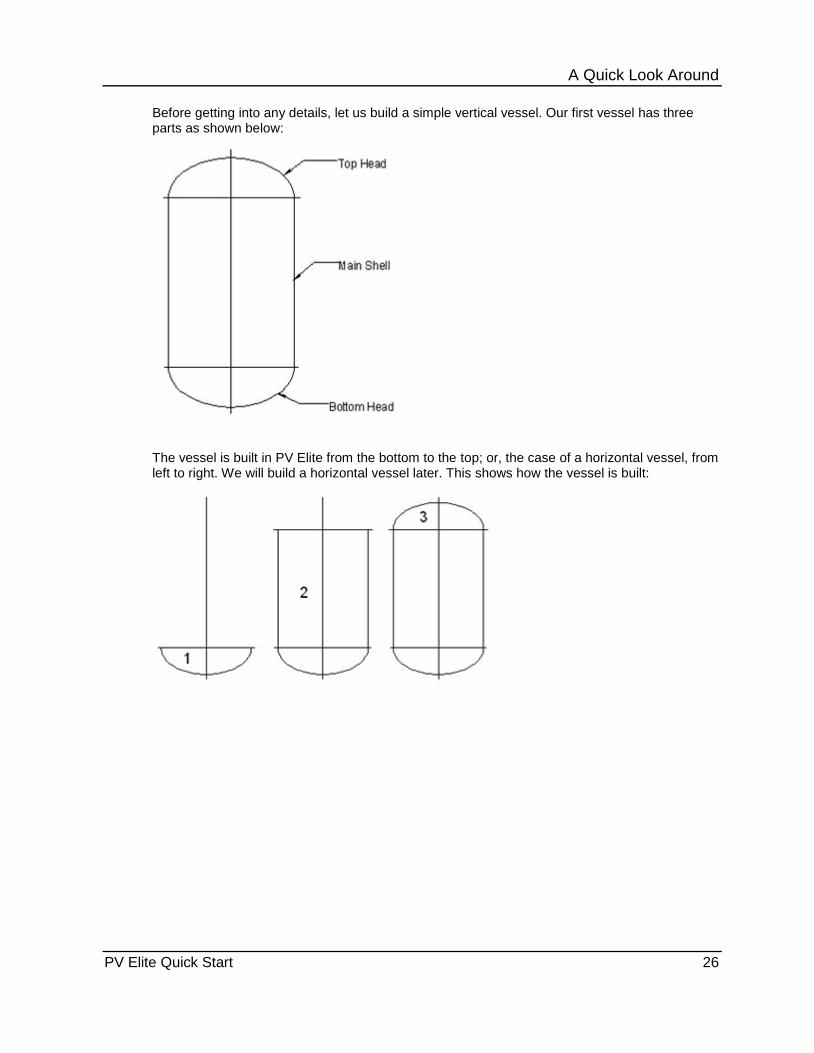
Before getting into any details, let us build a simple vertical vessel. Our first vessel has three parts as shown below:
The vessel is built in PV Elite from the bottom to the top; or, the case of a horizontal vessel, from left to right. We will build a horizontal vessel later. This shows how the vessel is built:
A Quick Look Around
PV Elite Quick Start 27
In This Section Component Buttons ....................................................................... 27 Building the Vessel from the Bottom Up ........................................ 28 Dimensions .................................................................................... 29 Material Specification ..................................................................... 33 Updating the Other Components in the Vessel ............................. 35 The Status Bar at the Bottom of the Screen .................................. 36 The Output Processor .................................................................... 36 Generating and Printing the Final Pressure Vessel Report ........... 38 Data Input – Other information ...................................................... 39 Design Constraints (Global Settings in PV Elite) ........................... 40 Inserting a Component .................................................................. 45 Deleting a Component ................................................................... 46 Node Numbers ............................................................................... 46 Adding a Nozzle to the Model ........................................................ 47 Nozzle Orientation Around the Vessel ........................................... 48 Flip Model Orientation .................................................................... 49
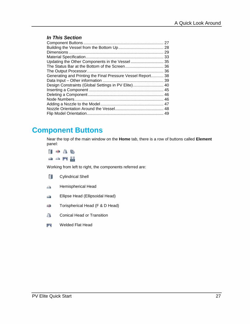
Component Buttons Near the top of the main window on the Home tab, there is a row of buttons called Element panel:
Working from left to right, the components referred are:
Cylindrical Shell
Hemispherical Head
Ellipse Head (Ellipsoidal Head)
Torispherical Head (F & D Head)
Conical Head or Transition
Welded Flat Head

A Quick Look Around
PV Elite Quick Start 28
We will talk about the remaining commands later as I am sure you are anxious to start building your first vessel. Before we leave this subject however, if you let your mouse cursor hover over any of the buttons, you will get a ‘tool tip’, which briefly describes the function of the button:
Building the Vessel from the Bottom Up 1. Click Ellipse to place the bottom head.
2. Click Cylinder to place the main shell.
3. Click Ellipse again to place the top head.
If you look at the window to the right, the software displays a 3D view of the model.

A Quick Look Around
PV Elite Quick Start 29
4. You can switch to the 2D view by selecting the 2D View tab under the model representation.
5. If you want to go back to the 3D view, click the 3D View tab.
Dimensions PV Elite populates the height and other dimensions for your vessel with sample data, which you can alter to your vessel specifics. PV Elite made certain assumptions as you built the model, including diameter, thicknesses, lengths, and materials.
1. Before we look at the dimensions, select the bottom head in either the 2D or 3D model. This will select the bottom head as the current component.
If you look at the 2D model, you will see that the bottom head is a lighter color.

A Quick Look Around
PV Elite Quick Start 30
2. Let us look at the dimensions PV Elite chose for the current component (the lighter color in the illustration above). The details will look like this:
Here are the major assumptions for this example:
Inside Diameter: 96 inches Straight Flange: 0.1667 feet (which is 2 inches) Finished Thickness: 0.25 inches Internal Corrosion: 0.125 inches External Corrosion: 0 Internal Pressure: 100 psi External Pressure: 15 psi Temperatures: 100 °F Head Aspect Ratio: 2 (Head Factor)
There is other information, but let us make some changes to suit our vessel. First we change the dimensions and the pressure:
A Quick Look Around
PV Elite Quick Start 31
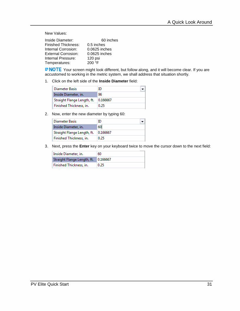
New Values:
Inside Diameter: 60 inches Finished Thickness: 0.5 inches Internal Corrosion: 0.0625 inches External Corrosion: 0.0625 inches Internal Pressure: 120 psi Temperatures: 200 °F
Your screen might look different, but follow along, and it will become clear. If you are accustomed to working in the metric system, we shall address that situation shortly.
1. Click on the left side of the Inside Diameter field:
2. Now, enter the new diameter by typing 60:
3. Next, press the Enter key on your keyboard twice to move the cursor down to the next field:

A Quick Look Around
PV Elite Quick Start 32
4. If you do not want to change the straight flange, press Enter again, and it will move to the next field. You should be able to complete the entries for your new dimensions:

A Quick Look Around
PV Elite Quick Start 33
Material Specification Now we are going to change the material from SA-516 70 to SA 240 316L.
1. In the Material Name field, type SA240316L. Don't worry about spaces or dashes.
A new dialog displays.

A Quick Look Around
PV Elite Quick Start 34
2. Select the first entry in the list.
The Material Properties dialog displays.
This screen gives you information about the material you have chosen.
3. Click Select and the material for your bottom head will change as follows:

A Quick Look Around
PV Elite Quick Start 35
Updating the Other Components in the Vessel So far, we have entered the new data for the bottom head element. Also, if you look at the screen you will see the geometry difference of your bottom head to the rest of the elements:
The vessel looks like this because we have not updated the remaining components (main shell and top head) data fields. We are going to use a shortcut to copy the values for the bottom to the remaining components.
1. Click Share Information located in the Utility panel of the Home tab.
The Data Share Dialog displays.
Notice the boxes that have been checked. The checked items will be shared with all the other upper components. Make sure you have checked only the boxes shown in this example.

A Quick Look Around
PV Elite Quick Start 36
2. Click OK.
PV Elite updates all the components with the new data.
Your model now looks more realistic. You can see that at least the diameter of the bottom head has been shared with the main shell and top head.
The Status Bar at the Bottom of the Screen So far we have only entered the data relevant to our vessel, and produced the model on the screen. In this section, you'll understand the Status Bar fields.
1. Select the main shell in either the 2D or 3D view.
The main shell element is highlighted.
2. Look at the bottom of the screen to the status bar:
The status bar gives us a lot of information for the selected component. Let us consider the fields from left to right:
El# 2 of 3 : Component number 2 of 3 components (from the bottom) Fr: 0.00 To: 4.00 ft : Element spans from 0.00 ft to 4.00 ft from the datum line Up: : Element orientation Tr: 0.3420 : Computed thickness for the internal pressure (120 psi) Mawp: 206.8 : MAWP for this element (206.8 psi) MAPnc: 275.6 : Maximum allowable pressure new and cold (275.6 psi) Trext: 0.328 : Computed thickness for the external pressure Slen: 22.7 ft : Maximum unsupported length for the external pressure
Let us now see what happens when there is a problem with an element.
3. Go to Finished Thickness field, and change the thickness from 0.5 inches to 0.2 inches.
4. Now look at the status bar at the bottom of the screen:
The required thickness for the internal and external pressures now appears in red, indicating that there is a problem. In our case, the problem is the thickness.
5. Change the thickness back to 0.5 inches to fix the problem.
The Output Processor Now that we have built our simple model, we need to get the complete details of the calculations performed by PV Elite.
Click Save and save your model using the name My Vertical Vessel.

A Quick Look Around
PV Elite Quick Start 37
1. Click Analyze .
When the analysis finishes, the Output Processor displays.
Your screen may look different, but it can easily be changed to look like the illustration above.
The left window has the heading Report List. In the right window is the prompt Select one or more reports from the Report List to view or print.
2. Click Internal Pressure Calculations from the list.
The right pane now shows the results of the item you selected in the left window pane. The output window now looks as shown below.
3. You can scroll up and down to look at the complete calculation for the internal pressure computations.

A Quick Look Around
PV Elite Quick Start 38
Generating and Printing the Final Pressure Vessel Report
Now that we have looked at the output for the Internal Pressure Calculations, we will learn how to include different items in your final report.
1. While holding down the CTRL key on your keyboard, click on the items that you want
included from the Report List (left) window.
2. After you select the items, we are ready to generate the report.
3. If you want to send the output to a printer, then click Print . This prints the report immediately with page numbers and headings on each page.
There are other options. For example, you might find it convenient to send the output to Microsoft Word® if you have it installed on your computer. This feature allows you to edit the results and add your own notes or comments.
You can send the output to a text file by selecting Print to file. You are prompted for a file name. This will be a text file with a filename extension of .txt. You will be able to access this file with any text editor such as Notepad, or Microsoft Word. When you send the output to a text file, all the colored text will be lost, and will simply be in black font color.
You can also the output to a PDF file by clicking Print to PDF on the Preview/Print pane of the File tab. Bookmarks are created for each report included in the file, so you can easily select the report you wish to view. If you select Insert 2D Page or Insert 3D Page, you can also include the model of the vessel in the PDF file.
A Quick Look Around
PV Elite Quick Start 39
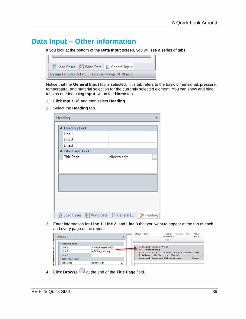
Data Input – Other information If you look at the bottom of the Data Input screen, you will see a series of tabs:
Notice that the General Input tab is selected. This tab refers to the basic dimensional, pressure, temperature, and material selection for the currently selected element. You can show and hide
tabs as needed using Input on the Home tab.
1. Click Input , and then select Heading.
2. Select the Heading tab.
3. Enter information for Line 1, Line 2, and Line 3 that you want to appear at the top of each and every page of the report.
4. Click Browse at the end of the Title Page field.
A Quick Look Around
PV Elite Quick Start 40
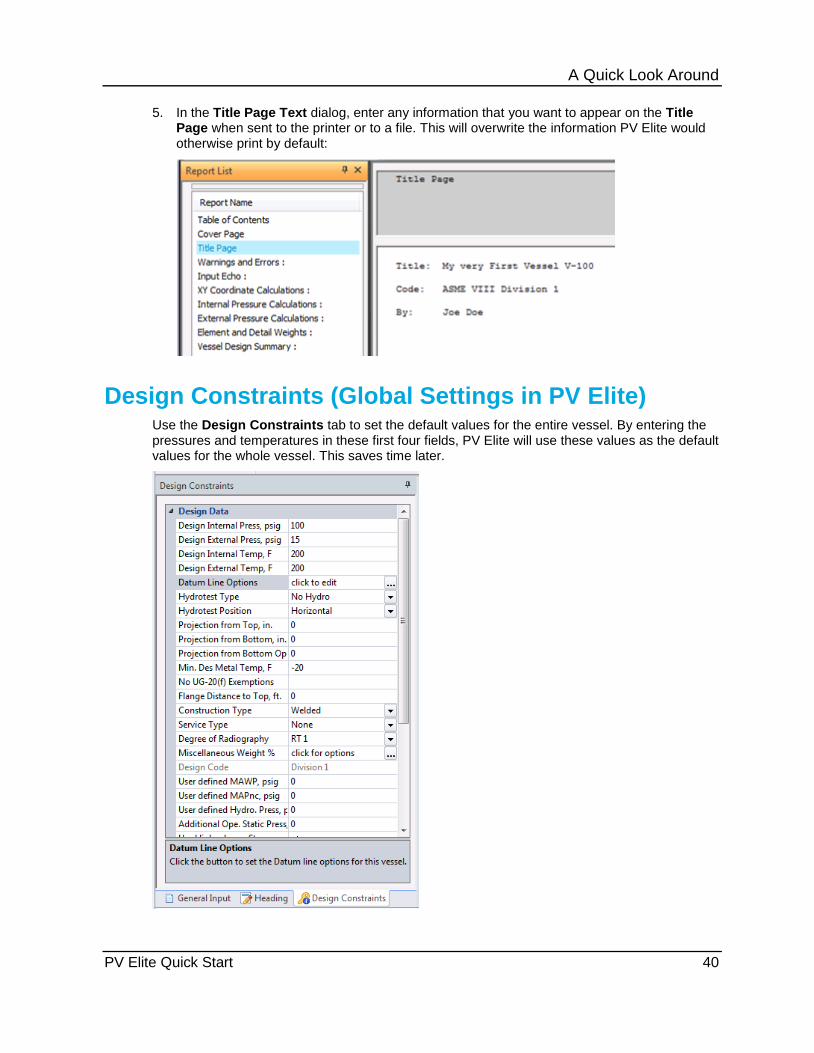
5. In the Title Page Text dialog, enter any information that you want to appear on the Title Page when sent to the printer or to a file. This will overwrite the information PV Elite would otherwise print by default:
Design Constraints (Global Settings in PV Elite) Use the Design Constraints tab to set the default values for the entire vessel. By entering the pressures and temperatures in these first four fields, PV Elite will use these values as the default values for the whole vessel. This saves time later.

A Quick Look Around
PV Elite Quick Start 41
Some of the other design constraints that you might what to consider are discussed below.
Datum Line Options
1. Click the 3D View tab.
PV Elite has located the datum line at the tangent line of the bottom head. We can change the location of the datum line at any time to move it to a more convenient location.
2. Click Browse at the end of the Datum Line Options field.
3. Type 3 for the Vertical Vessels offset, and then click OK. This sets the datum line to 3 feet up from its current location.
After you have a skirt attached to the bottom of the vessel, you might want to move the datum line to the bottom of the skirt.
Hydrotest Type and Position of the Hydrotest
Select the type of hydrotest. For Division 1, the software provides the following methods to determine hydrotest pressure. Select one of the following:
UG-99b - ASME UG-99 (b), Division 1. The hydrotest pressure is 1.3 times (1.5 for pre-99 addenda) the maximum allowable working pressure for the vessel multiplied by the lowest ratio of the stress value S for the test temperature to the stress value S for the design temperature. This type of hydrotest is normally used for non-carbon steel vessels for which the allowable stress changes with temperature, starting even at a somewhat low temperature.
UG-99c - ASME UG-99(c), Division 1. The hydrotest pressure is determined by multiplying the minimum MAP by 1.3 (1.5 for pre-99 addenda) and reducing this value by the hydrostatic head on that part. The hydrostatic head is calculated based on the dimensions of the vessel and by values for Projection from Top, Projection from Bottom, and Projection from Bottom Oper. In addition, Hydrotest Position is used to determine the head pressure.

A Quick Look Around
PV Elite Quick Start 42
UG-99b(36) - ASME UG-99(b), footnote 36, Division 1. The hydrotest pressure is 1.3 times (1.5 for pre-99 addenda) the design pressure for the entire vessel, multiplied by the lowest ratio of the stress value Sa for the test temperature to the stress value S for the design temperature.
UG-100 - ASME UG-100 pneumatic test. The test pressure is 1.1 times (1.25 for pre-99 addenda) the maximum allowable working pressure for the entire vessel, multiplied by the lowest ratio of the stress value Sa for the test temperature to the stress value S for the design temperature.
The stress ratio mentioned above includes bolt allowable stresses for flanges that are designed according to Appendix 2. This allowance usually results in a ratio of 1. See ASME Interpretation VIII-1-83-260 for more information. Click Tools > Configuration to turn off this option, resulting in a ratio greater than one in cases in which the operating and ambient stresses for the vessel parts are not the same.
No Hydro - No hydrotest pressure.
User Entered Pressure
1.43 * MAWP (PED)
App. 27-4 - ASME Appendix 27-4, Division 1. The hydrotest pressure is 1.3 times the maximum allowable working pressure for the vessel multiplied by the lowest ratio of the stress value S for the test temperature to the stress value S for the design temperature. This type of hydrotest is normally used for glass-lined vessels.
For Division 2, the software provides the following methods to determine hydrotest pressure. Select one of the following:
AT-300 - ASME AT-300, Division 2, based on vessel design pressure. The hydrotest pressure is 1.25 times the design pressure marked on the vessel, multiplied by the lowest ratio of the stress intensity value Sm for the test temperature to the stress intensity value Sm for the design temperature. This type of hydrotest is normally used for non-carbon steel vessels for which the allowable stress changes with temperature starting even at a somewhat low temperature.
AT-301 - ASME AT-301, Division 2, based on calculated pressure. A hydrostatic test based on a calculated pressure is allowed by agreement between the user and the manufacturer. The hydrostatic test pressure at the top of the vessel is the minimum of the test pressures calculated by multiplying the basis for calculated test pressure for each element by 1.25 and then reducing this value by the hydrostatic head on that element.
AT-410 - ASME AT-410, Division 2, based on vessel design pressure. The pneumatic test pressure shall be no less than 1.15 times the design pressure multiplied by the lowest ratio of the stress value S for the test temperature to the stress value S for the design temperature.
Hydrostatic
Pneumatic
No Hydro - No hydrotest pressure.
User Entered Pressure
The next box lets you specify which position the vessel will be during the hydrotest:
Select a hydrotest position. This input is required so that the total static head can be

A Quick Look Around
PV Elite Quick Start 43
determined and subtracted when UG-99c is selected for Hydrotest Type. This value is used in conjunction with Projection from Top, Projection from Bottom, and Flange Distance to Top to determine the total static head. Select from the following:
Vertical - The vessel is tested in the upright or vertical position. This is not common.
Horizontal - The vessel is tested in the horizontal position. This is common for most vessels. The vessel is on its side (in the case of a vertical vessel) or in its normal position (for a horizontal vessel).
Tall towers for example, are usually hydrotested in the horizontal position. PV Elite has to compute the hydrostatic pressure from the water in the vessel at hydrotest time. If the vessel is tested in the vertical positions, the pressure at the bottom of the vessel will be greater than if the vessel is tested in the horizontal position. Give careful consideration to the position that is appropriate to your situation.
Miscellaneous Weight %
Click to open the Miscellaneous Weight Percent Inclusion dialog box. This dialog box lets you specify to increase the mass of various elements and their details. There are three methods for applying the percentage of extra weight to use:
1. Use a single percentage for all components - Increases all metallic elements of the vessel by a certain percentage. In the Miscellaneous Weight Percent for all Items box, type a percentage value to include additional weight which accounts for vessel attachments and internal items not otherwise included in the vessel. Typical values are 3.0 or 5.0. The software multiplies the total weight of the vessel by 1.0 plus this value converted to a decimal value (such as 1.03 or 1.05). Type 0 if no additional weight is needed.
2. Use individual percentages for the different components - Increases the weight of an item by the percentage specified for the item in the Miscellaneous Weight Percentages section.
3. Add percentages to increase weights of shells and heads - Increases the weights of the shells and heads by the sum of the percentage increase for nozzles, clips, and piping.
If you use this option and model the nozzles or clips, the weight will be excessive.
When using this option, the software calculates the weight of platforms automatically. You only need to specify the following information:
Is There a Top Head Platform? - Enables the additional weight fields.
Top Head Platform Uniform Weight - Specifies the grating weight from which the top head platform is constructed.
Circular Platform Uniform Weight - Specifies the grating weight from which the circular platforms are constructed.
Ladder Uniform Weight - Indicates the weight of the ladder per unit length.
The top head platform, if specified, is square. The width the software uses to calculate the area is the larger of 4.5 feet (1.3716 meters) or the vessel inside diameter at the top
A Quick Look Around
PV Elite Quick Start 44
head. Ultimately, the software adds the weight of the platform to the weight of the top head.
Circular platforms are placed every 20 feet (6.096 meters) along the height of the vessel. The platforms are 3.5 feet (1.0668 meters) wide and sweep 180 degrees. PV Elite calculates the weights of the platforms. The software then adds the value to the mass of the element on which the platforms would theoretically exist, based on the dimension from the base of the skirt.
The software also calculates the total weight of ladders along the vessel. In addition, PV Elite proportions the total ladder weight to each element based on the element's length.
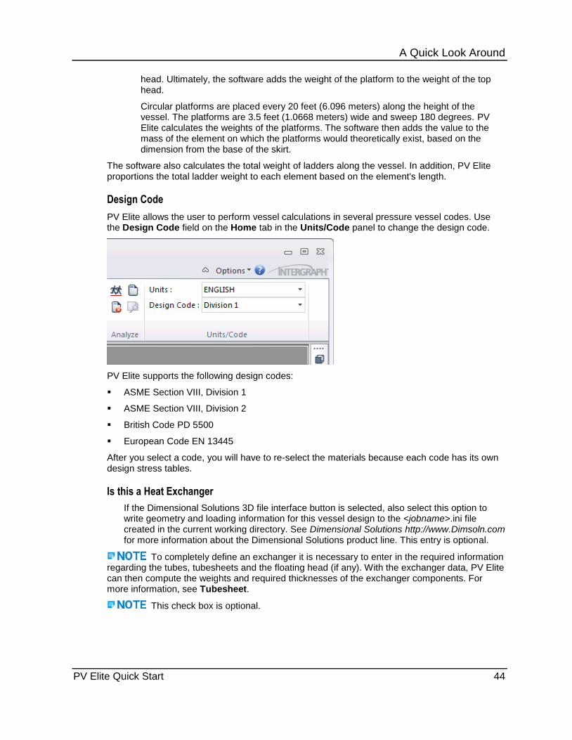
Design Code
PV Elite allows the user to perform vessel calculations in several pressure vessel codes. Use the Design Code field on the Home tab in the Units/Code panel to change the design code.
PV Elite supports the following design codes:
ASME Section VIII, Division 1
ASME Section VIII, Division 2
British Code PD 5500
European Code EN 13445
After you select a code, you will have to re-select the materials because each code has its own design stress tables.
Is this a Heat Exchanger
If the Dimensional Solutions 3D file interface button is selected, also select this option to write geometry and loading information for this vessel design to the <jobname>.ini file created in the current working directory. See Dimensional Solutions http://www.Dimsoln.com for more information about the Dimensional Solutions product line. This entry is optional.
To completely define an exchanger it is necessary to enter in the required information regarding the tubes, tubesheets and the floating head (if any). With the exchanger data, PV Elite can then compute the weights and required thicknesses of the exchanger components. For more information, see Tubesheet.
This check box is optional.

A Quick Look Around
PV Elite Quick Start 45
ASME Steel Stack
Select to perform an ASME steel stack analysis, based on the ASME recommended guidelines for Steel Stacks STS-2000 with addenda. This analysis is for circular stacks that meet the design requirements in the steel stack guidelines. The results are shown in the ASME STS Stack Calculations report. If Design Code is not set to Division 1 (ASME VIII-1), the stack analysis is not performed.
Also select this option if you are analyzing a steel stack and want to check it against ANSI/ASME STS-2000/STS-1a-2003. After the software completes the calculation, the program generates the Stress Due to Combined Loads report with a listing of the stack calculations. Compressive allowables in the report are calculated based on Section 4.4.
When selected, expand ASME Steel Stack and enter values for ASCE Wind Exposure, Factor of Safety, Mean Hourly Wind Speed, Is the Stack Lined?, and Importance Factor.
Read and understand the ASME stack guidelines. This is not a code like ASME Division 1 or 2, but a set of design guidelines for designers and engineers.
The following paragraphs from the stack guidelines are addressed:
4.4 Allowable Stresses
4.4.1 Longitudinal Compression, equations 4.7,4.8 and 4.9
4.4.2 Longitudinal Compression and Bending
4.4.3 Circumferential Stresses
4.4.4 Combined Longitudinal and Circumferential Compressive Stresses
4.4.5 Circumferential Compression in Stiffeners, equations 4.14, 4.15, 4.16
4.4.7 Minimum Structural Plate Thickness
5.2.2 Wind Responses, equations 5.3, 5.4 and (1),(2) and (3), (b) equations 5.5, 5.6 and 5.7
Design Modification
If any of the modifications is set to yes, PV Elite will correct the item should it fail in the analysis. For example, if Select Wall Thickness for Internal Pressure was set to Yes, PV Elite will automatically increase the thickness of a component should it not be thick enough.
Inserting a Component 1. In the 2D View, select the component below or above where you want to insert the new
component.
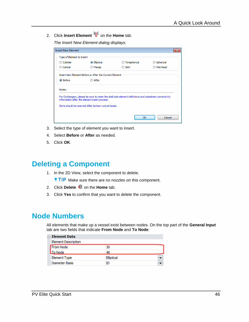
A Quick Look Around
PV Elite Quick Start 46
2. Click Insert Element on the Home tab.
The Insert New Element dialog displays.
3. Select the type of element you want to insert.
4. Select Before or After as needed.
5. Click OK.
Deleting a Component 1. In the 2D View, select the component to delete.
Make sure there are no nozzles on this component.
2. Click Delete on the Home tab.
3. Click Yes to confirm that you want to delete the component.
Node Numbers All elements that make up a vessel exist between nodes. On the top part of the General Input tab are two fields that indicate From Node and To Node:

A Quick Look Around
PV Elite Quick Start 47
Every main element (not attachments such as nozzles) has two nodes. Consider these two vessels shown below:
Notice that every element from the bottom to the top or from the left to the right exists between two node numbers. There is a From Node, and there is a To Node. In the case of the bottom (or left) head, the nodes are situated at the tangent line and the weld line.
Adding a Nozzle to the Model 1. Switch to the 2D View.
2. Select the component into which you want to add the nozzle.
3. Click Nozzle Input on the Home tab.
The Nozzle Input/Analysis dialog box displays.
Different nozzle configurations can be considered. The choices are basically nozzles without pads, nozzles with pads, protruding nozzles without pads, and protruding nozzles with pads. There are also special forged nozzles available for analysis.
4. Select the default nozzle attachment.
5. Click on the nozzle description field and change the description name of your nozzle to N1.
6. Select the next fields or press ENTER on your keyboard past the Diameter field to run your nozzle calculation. If your inputs fail the design code, you will notice the red warnings on the status bar at the bottom of the dialog box.

A Quick Look Around
PV Elite Quick Start 48
Also at the bottom of the Nozzle Analysis dialog box, you will see a calculator button below the status bar.
7. Click the calculator button to open the Quick Results Dialog. This screen will give you a quick calculation report of your current nozzle:
Nozzle Orientation Around the Vessel Let's look at the orientation of the nozzle around the vessel.

A Quick Look Around
PV Elite Quick Start 49
From the example shown above, the 0º position is at the top (North) and the nozzle at position 90º is to the right. Therefore, the angles of the nozzle increase in the clockwise direction. However the zero position can occupy the North, West or East position as you need. The angle can increase in the clockwise or the counter-clockwise direction. The controls are on the Configuration dialog screen. To get the Configuration dialog screen, go to the Tools tab, click Set Configuration Parameters, and then select the Set Default Values tab.
Flip Model Orientation If a new model is built in the vertical position and it needs to change orientation to the horizontal position for different analysis purposes; PV Elite is able to flip the model with a single button
found on the Tools tab, Flip Model Orientation .

PV Elite Quick Start 50
A A Quick Look Around • 25 Adding a Nozzle to the Model • 48
B Before You Begin PV Elite Installation • 20 Building the Vessel from the Bottom Up • 28
C Check Out a License • 19 Component Buttons • 27
D Data Input – Other information • 40 Deleting a Component • 47 Design Constraints (Global Settings in PV
Elite) • 41 Dimensions • 29
E ESL Installation • 12
F Flip Model Orientation • 51 Frequently Asked Questions (FAQ) • 16
G Generating and Printing the Final Pressure
Vessel Report • 39
I Inserting a Component • 46 Install a local lock • 12 Install a network lock • 12 Install SmartPlant License Checkout Utility •
17 Installation • 20 Installing PV Elite from the Product Media •
21 Installing PV Elite in Silent Mode • 22 Intergraph CAS Technical Support • 9 Introduction • 9
L License Checkout Utility Dialog Box • 18 Licensing • 11
M Material Specification • 32
N NetHASP License Manager / NETHASP.INI
Instructions • 13 Node Numbers • 47 Notes on Network ESLs • 13 Nozzle Orientation Around the Vessel • 50
P PV Elite Quick Start • 5
Q Quick Installation Workflow • 15
S Seminars • 9 SmartPlant License Manager Installation •
15
T The Output Processor • 37 The Status Bar at the Bottom of the Screen
• 37 Troubleshooting Network Locks • 15
U Updating the Other Components in the
Vessel • 35 Using the SmartPlant License Checkout
Utility • 17
V Verifying the Installed Product Program
Structure • 23
W What's New in PV Elite and CodeCalc • 6
Index

Index
PV Elite Quick Start 51


