52
PV System Components EE 495/695 Spring 2011

PV System Components
EE 495/695Spring 2011

Main Components of Grid-Connected PV systems
• Battery storage is added to some grid-tied PV systems.
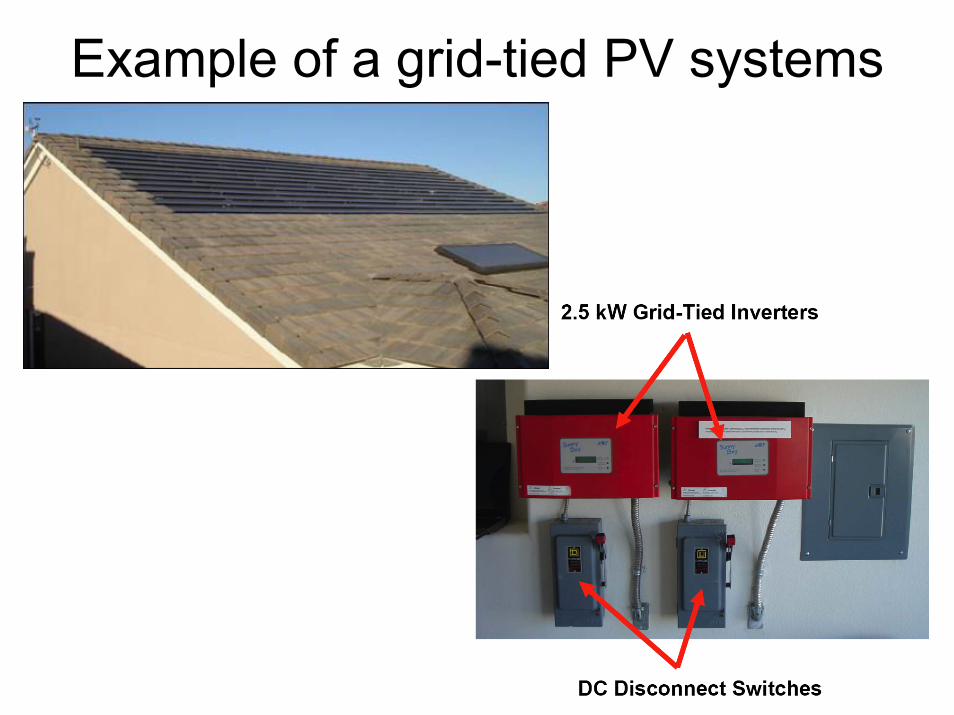
Example of a grid-tied PV systems
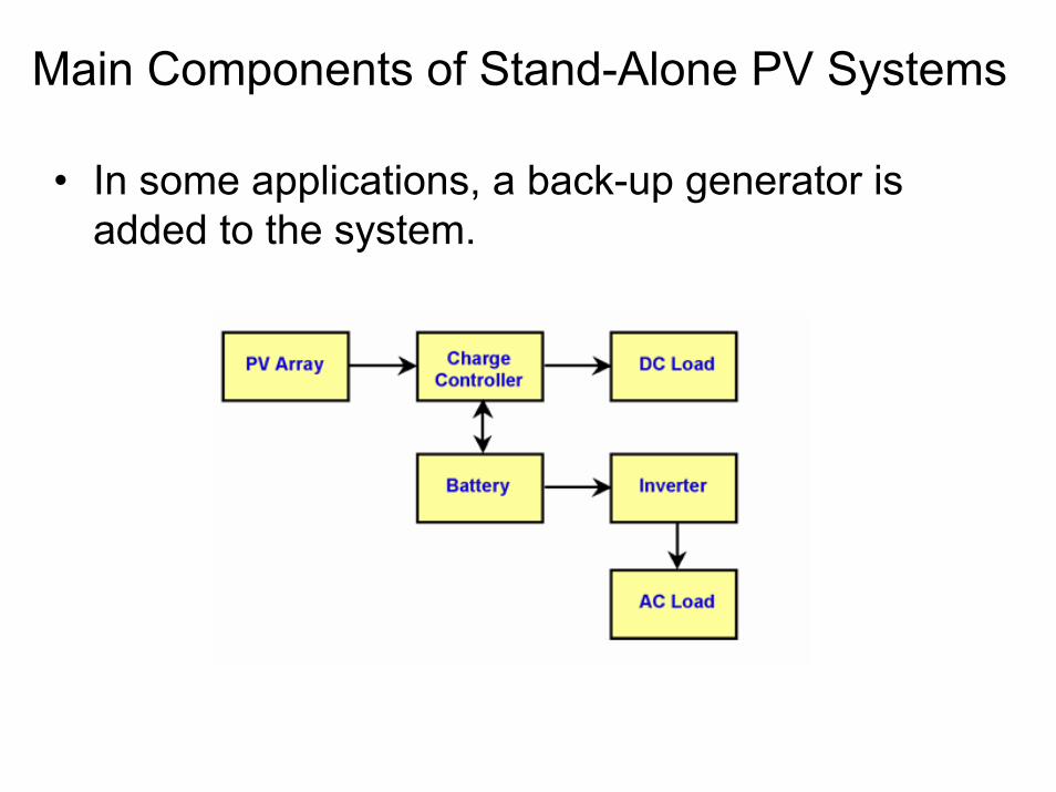
Main Components of Stand-Alone PV Systems
• In some applications, a back-up generator is added to the system.

Example of a stand-alone PV system

Additional Components (BOS)
• Wires, interconnect cables, switches, combiner boxes, circuit breakers, fuses and receptacles
• Ground fault, surge and lightning protection• Grounding devices

PV CellPV Cell

Diode Equation: Ideal Diode• The diode equation gives an expression for the current
through a diode as a function of voltage.
where:I = the net current flowing through the diode; I0 = "dark saturation current", V = applied voltage across the terminals of the diode; q = absolute value of electron charge = 1.60× 10⁻¹⁹ Ck = Boltzmann's constant = 1.38 × 10⁻²³ J/KT = absolute temperature (K).
• The "dark saturation current" (I0) is an extremely important parameter which differentiates one diode from another.
• Important Note: I0 increases with T.

DIODE I-V CURVE

Cell I-V Curve• The I-V curve of a solar cell is the superposition of the I-
V curve of the solar cell diode in the dark with the light-generated current IL. The equation for the I-V curve in the first quadrant is:
where IL = light generated current, and n is the ideality factor (n=1 for ideal cases)
• The light has the effect of shifting the I-V curve down into the fourth quadrant where power can be extracted from the diode.
• The -1 term in the above equation can usually be neglected since the exponential term is usually >> 1.

SHIFT OF I-V CURVE

SHIFT OF I-V CURVE

Final I-V Curve

SHORT CIRCUIT CURRENT• The short-circuit current is the current through the solar cell
when the voltage across the solar cell is zero (i.e., when the solar cell is short circuited).
• The short-circuit current is due to the generation and collection of light-generated carriers. Therefore, the short-circuit current is the largest current which may be drawn from the solar cell.
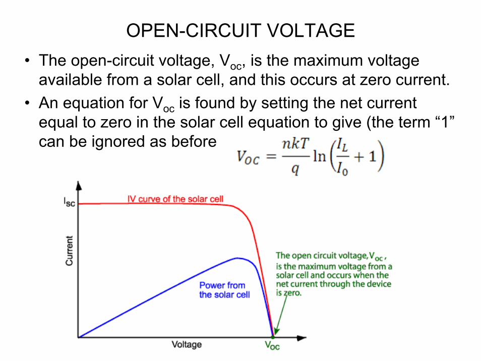
OPEN-CIRCUIT VOLTAGE• The open-circuit voltage, Voc, is the maximum voltage
available from a solar cell, and this occurs at zero current. • An equation for Voc is found by setting the net current
equal to zero in the solar cell equation to give (the term “1”can be ignored as before

FILL FACTOR• The "fill factor", more commonly known by its abbreviation
"FF", is a parameter which, in conjunction with Voc and Isc, determines the maximum power from a solar cell.
• Graphically, the FF is a measure of the "squareness" of the solar cell curve.
• Mathematically, the FF is defined as the maximum power divided by the product of Isc with Voc, i.e.,

• A commonly used expression for the FF can be determined empirically as:
where voc is defined as a "normalized Voc”
• Silicon cells have a FF ranging between 0.82 and 0.85.• GaAs solar cell may have a FF approaching 0.89.

Effect of Temperature• Like all other semiconductor
devices, solar cells are sensitive to temperature.
• In a solar cell, the parameter most affected by an increase in temperature is the open-circuit voltage.
• The open-circuit voltage decreases with temperature because of the temperature dependence of I0 .
• For silicon devices, the open circuit voltage drops by approximately -2.2 mV/oC.
• The short-circuit current increases slightly with temperature. However, this is a small effect (≈ +0.6 mA/oC)

Effect of Light Intensity• Changing the light intensity incident on a solar cell changes all
solar cell parameters, including the short-circuit current, the open-circuit voltage, the FF, and the efficiency.
• The light intensity on a solar cell is often called the number of suns, where 1 sun corresponds to standard illumination at AM1, or 1 kW/m2.
• For example a system with 10 kW/m2 incident on the solar cell would be operating at 10 suns, or at 10X.
• A PV module designed to operate under 1 sun conditions is called a "flat plate" module while those using concentrated sunlight are called "concentrators".

CELL EFFICIENCY• The efficiency is the most commonly used parameter to
compare the performance of one solar cell to another. Efficiency is defined as the ratio of energy output from the solar cell to input energy from the sun.
• In addition to reflecting the performance of the solar cell itself, the efficiency depends on the spectrum and intensity of the incident sunlight and the temperature of the solar cell.
• Therefore, conditions under which efficiency is measured must be carefully controlled in order to compare the performance of one device to another. Terrestrial solar cells are measured under AM1.5 conditions and at a temperature of 25°C.

Trend in Cell Efficiencies

PV ModulePV Module• To obtain sufficient voltage, current and power, the cells are
connected together in series to form a PV module (or panel). • The cells are encapsulated to protect them and their interconnecting
wires from the typically harsh environment.• The voltage of a PV module is usually chosen to be compatible with
a 12V battery. Hence, many modules contain 36 solar cells in series.
• This gives an open-circuit voltage of about 21V under standard test conditions, and an operating voltage at maximum power and operating temperature of about 17 or 18V.

IV Curve of PV ModuleIV Curve of PV Module• If all the N solar cells in a module have identical electrical
characteristics, and they all experience the same irradiance andtemperature, then all the cells will be operating at exactly thesame current and voltage.
• In this case, the I-V curve of the PV module has the same shape as that of the individual cells, except that the voltage is increase N times.
ISC
N VOC

Electrical Specs. of SM50W (13”x48”x1.3”)

Heat Generation in PV Modules• A PV module exposed to sunlight
generates heat as well as electricity. • For a typical commercial PV module
operating at its maximum power point, only 10 to 15% of the incident sunlight is converted into electricity, with much of the remainder being converted into heat.
• The factors which affect the heating of the module are: – the reflection from the top surface of
the module; – the electrical operating point of the
module; – absorption of sunlight by the PV
module in regions which are not covered by solar cells;
– the packing density of the solar cells.

PV Module Temperature• The encapsulation alters the heat flow into and out
of the PV module, thereby increasing the operating temperature of the PV module. – These increases in temperature have a major impact on
the PV module by reducing its voltage, thereby lowering the output power.
– In addition, elevated temperatures increase stresses associated with thermal expansion and also increase degradation rates by a factor of about two for each 10°C increase in temperature.
• The operating temperature of a module is determined by the equilibrium between the heat produced by the PV module, the heat lost to the environment and the ambient operating temperature.

Heat Loss in PV Modules• The heat lost to the environment can proceed via one of
three mechanisms: conduction, convection and radiation. • These loss mechanisms depend on the thermal resistance
of the module materials, the emissive properties of the PV module, and the ambient conditions (especially wind speed).
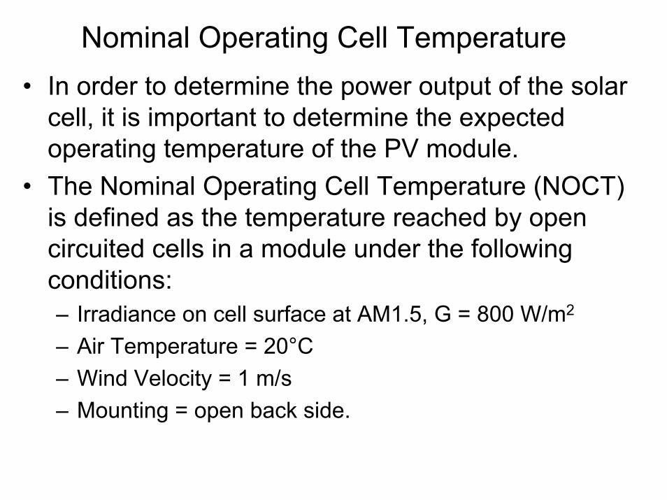
Nominal Operating Cell Temperature• In order to determine the power output of the solar
cell, it is important to determine the expected operating temperature of the PV module.
• The Nominal Operating Cell Temperature (NOCT) is defined as the temperature reached by open circuited cells in a module under the following conditions:– Irradiance on cell surface at AM1.5, G = 800 W/m2
– Air Temperature = 20°C – Wind Velocity = 1 m/s– Mounting = open back side.

Cell Temperature• NOCT: The best case include
aluminium fins at the rear of the module for cooling which reduces the thermal resistance and increases the surface area for convection.
• The best module operated at a NOCT of 33°C, the worst at 58°C and the typical module at 48°C respectively.
• An approximate expression for calculating the cell temperature is given by
• Module temperature will be lower than this when wind velocity is high, but higher under still conditions.
NOCT for best case, worst case and average PV modules
GNOCTTT Ac 8.020−
+=

PV Array
• In applications requiring large amounts of power, several PV modules are connected in series and/or parallel to form a PV array.
• A series-connected set of solar cells or modules is called a "string". – A series connection builds up the
voltage.– A parallel connection builds up the
current.• Example: Refer to the array to the right with
4 strings. Each string consists of 6 panels. The open circuit voltage and short circuit current of each panel is 21 V and 3.5 A. the rated power of each panel is 48 W. calculate – The rated power of the array – The open circuit voltage of the array– The short-circuit current of the array

Functions of Storage in PV Systems
• In stand alone electricity generating systems, some form of storage is needed unless the load is exactly matched to the time during which the sun is shining (e.g., water pumping for irrigation).
• In stand alone systems, energy storage is needed to– power loads at night, – allow a load to operate during cloudy weather (the number of
days of storage needed depends on the weather pattern at a particular location, with cloudier locations needing more storage).
– buffer the system against periods of low insolation, such as in winter,
– provide higher currents to the load than the array alone can provide during sunny conditions. This is especially useful for motor who have a high current draw on start-up.

Energy Storage in PV Systems• There are numerous types of energy storage. By far the
most common type of storage in PV systems is chemical storage, in the form of a battery.
• Because of large impact of batteries in a stand-alone photovoltaic system, understanding the properties of batteries is critical.
• An ideal battery would be able to be charged and discharged indefinitely under arbitrary charging-discharging regimes, would have no losses and no self discharge. However, in practice, no battery can achieve these requirements.

Battery Basics• A battery converts energy stored in the chemical bonds of
a material into electrical energy via a set or oxidation/reduction (redox) reactions. – Redox reactions are chemical reactions in which an
electron is either required or produced by the chemical reaction.
• For primary batteries, this is a one-way process – the chemical energy is converted to electrical energy, but the process is not reversible and electrical energy cannot be converted to chemical energy. These batteries cannot be recharged.
• In a secondary battery, the conversion process between electrical and chemical energy is reversible, – chemical energy is converted to electrical energy, and electrical energy can be converted to chemical energy, allowing the battery to be recharged.
• For photovoltaic systems, batteries must be rechargeable.

Starting Batteries and Deep Cycle Batteries• Starting batteries:
– Lead acid batteries designed for starting automotive engines are not designed for deep discharge. They have a large number of thin plates designed for maximum surface area, and therefore maximum current output, but can easily be damaged by deep discharge.
– Repeated deep discharges will result in capacity loss and ultimately in premature failure, as the electrodes disintegrate due to mechanical stresses that arise from cycling.
• Deep cycle batteries– Specially designed deep-cycle cells are much less
susceptible to degradation due to cycling, and are required for applications where the batteries are regularly discharged, such as photovoltaic systems, electric vehicles (golf carts, electric cars).
– These batteries have thicker plates that can deliver less peak current, but can withstand frequent discharging.

Lead Acid Batteries• Lead acid batteries are available in vented (flooded) and
non-vented (sealed).• Gel cells are sealed batteries where silica is added to the
electrolyte.• Absorbed Glass Mat (AGM) are also sealed and have a
highly absorbent glass mat separators between the plates to bind the electrolyte.

Operation of Lead Acid Batteries• A lead acid battery consists of a negative electrode (made
of porous lead to facilitate the formation and dissolution of lead), and a positive electrode which consists of lead oxide. Both electrodes are immersed in a electrolytic solution of sulfuric acid and water.
• Lead acid batteries store energy by the reversible chemical reaction shown below. The overall chemical reaction is:
• At the negative terminal the charge and discharge reactions are:
• At the positive terminal the charge and discharge reactions are:

Battery discharging
• Discharging a battery causes the formation of lead sulfate crystals at both the negative and positive terminals, as well as the release of electrons due to the change in valence charge of the lead.
• The formation of this lead sulfate uses sulfate from the sulfuric acid electrolyte surrounding the battery. As a result the electrolyte becomes less concentrated.
• Full discharge would result in both electrodes being covered with lead sulfate, and water (rather than sulfuric acid) surrounding the electrodes. In practice, however, discharging stops at the cutoff voltage, long before this point.
• If the battery is left at low states of charge for extended periods of time, large lead sulfate crystals can grow, which permanently reduces battery capacity. These larger crystals are difficult to convert back into lead.

Battery Charging• The charging reaction converts the lead sulfate at the
negative electrode to lead. At the positive terminal the reaction converts the lead to lead oxide. – During the first part of the charging cycle, the
conversion of lead sulfate to lead and lead oxide is the dominant reaction.
– However, as charging proceeds and most of the lead sulfate is converted to either lead or lead dioxide, the charging current electrolyzes the water from the electrolyte and both hydrogen and oxygen gas are evolved, a process known as the "gassing" of the battery.
• If current is being provided to the battery faster than lead sulfate can be converted, then gassing begins before all the lead sulfate is converted, that is, before the battery is fully charged.

Battery Charging• Gassing introduces several problems into a lead acid
battery:– Not only does the gassing of the battery raise safety
concerns, due to the explosive nature of the hydrogen produced, but also reduces the water in the battery, which must be manually replaced, introducing a maintenance component.
– In addition, gassing may cause the shedding of active material from the electrolyte, thereby permanently reducing battery capacity. For these reasons, the battery should not regularly be charged above the voltage which causes gassing.

Battery Charging methods• Constant Voltage A constant voltage charger is basically a DC
power supply which in its simplest form may consist of a step down transformer from the mains with a rectifier to provide the DC voltage to charge the battery. Such simple designs are often found in cheap car battery chargers.
• Constant Current Constant current chargers vary the voltage they apply to the battery to maintain a constant current flow, switching off when the voltage reaches the level of a full charge.
• Pulsed charge Pulsed chargers feed the current to the battery in pulses. The charging rate can be precisely controlled by varying the width of the pulses. During the charging process, short rest periods of 20 to 30 ms, between pulses allow the chemical actions in the battery to stabilize.
• Negative Pulse Charging is used in conjunction with pulse charging. it applies a very short discharge pulse during the charging rest period to dislodge any gas bubbles which have built up on the electrodes during fast charging, speeding up theoverall charging process.

Battery Charging methods (cont.)• IUI Charging. In here, the battery initially is charged at a
constant (I) rate until the cell voltage reaches a preset value - near gassing. Then the charger switches into constant voltage (U) phase and the current drawn by the battery will gradually drop until it reaches another preset level. Finally, the charger switches again into constant current mode (I) and the voltage continues to rise up to a new higher preset limit when the charger is switched off.
• Trickle charge Trickle charging is designed to compensate for the self discharge of the battery.

Flooded Lead acid batteries require boost charging (or equalization charging)
• Flooded lead acid batteries require periodic maintenance. Not only must the level of water in the electrolyte be regularly monitored by measuring its specific gravity, but these batteries also require "boost charging“ which involves short periodic overcharging to preventing stratification of the electrolyte in the battery.
• In addition, boost charging also assists in keeping all batteries at the same capacity.
• Sealed or valve regulated lead acid batteries do not need boost charging. However, these batteries typically require a more precise and lower voltage charging regime (to minimize gassing). In addition, these batteries are more sensitive to temperature variations, hence the charging regime does require some sort of temperature compensation.

Impact of charging regime• The charging regime also plays an important part in
determining battery lifetime. Overcharging or undercharging the battery results in either the shedding of active material or the sulfation of the battery, thus greatly reducing battery life.

Battery Capacity• The battery capacity C is a measure of the amount of
charge. The fundamental units of battery capacity is Amp-hrs (Ah).
• Battery capacity depends on the discharge rate and battery temperature.
• The battery capacity that battery manufacturers print on a battery is usually the product of 20 hours multiplied by the maximum constant current that a new battery can supply for 20 hours at 75 F°, down to a predetermined terminal voltage .

Effect of discharge rate and temperature on battery capacity
C/x refers to the battery discharge in x hours.

Voltage variation during charge and discharge
• A lead acid battery will experience a gradual change in the voltage during charging and discharging.
• Typical variation of cell voltage and specific gravity during discharge and charge:

Typical 12V battery voltage as function of SOC

Battery voltage and State Of Charge (SOC)
• Battery voltage level is commonly used to determine approximately the battery’s state of charge.
• The most accurate way to determine the battery’s SOC is by measuring the specific gravity of the electrolyte.

Depth Of Discharge (DOD) • Relation between DOD and SOC:
DOD = 100 – SOC• The DOD in conjunction with the battery capacity is a
fundamental parameter in the design of a battery bank for a PV system, as the energy which can be extracted from the battery is found by multiplying the battery capacity by the depth of discharge.
• Impact of daily DOD on battery life:

Battery Lifetime• Over time, battery capacity degrades due to sulfation of the
battery and shedding of active material. The degradation of battery capacity depends most strongly on the interrelationship between the following parameters: – the charging/discharging regime which the battery has
experienced; – the DOD of the battery over its life; – the average temperature of the battery over its lifetime.

Safety• Batteries are potentially very dangerous and users should
be aware of three main hazards: – The sulfuric acid in the electrolyte is corrosive.
Protective clothing in addition to foot and eye protection are essential when working with batteries.
– Batteries have a high current generating capability.If a metal object is accidentally placed across the terminals of a battery, high currents can flow through this object. Working tools should have insulated handles.
– Explosion hazards due to evolution of hydrogen and oxygen gas. During charging, particularly overcharging, batteries may evolve a potentially explosive mixture of hydrogen and oxygen gas. To reduce the risk of explosion, ventilation is used to prevent the buildup of these gasses and potential ignition sources should be eliminated from the battery enclosure.

Battery charge/discharge trends• In general, the larger the amount of storage included, the
less sensitive the system will be to periods of low insolation, and the more reliable the power will be.
Battery state of charge over a year showing the battery discharge overnight, during cloudy weather and seasonal variations.


