82
Service Manual Trucks Group 35 Lighting Control Module (LCM) Fault Codes VN, VHD VERSION2 PV776-20 033682
| Date post: | 25-Oct-2015 |
| Category: |
Documents |
| Upload: | registr-registr |
| View: | 1,252 times |
| Download: | 21 times |

Service ManualTrucks
Group 35Lighting Control Module (LCM) Fault Codes
VN, VHD VERSION2
PV776-20 033682


Foreword
The descriptions and service procedures contained in this manual are based on designsand methods studies carried out up to August 2005.
The products are under continuous development. Vehicles and components producedafter the above date may therefore have different specifications and repair methods.When this is believed to have a significant bearing on this manual, supplementaryservice bulletins will be issued to cover the changes.
The new edition of this manual will update the changes.
In service procedures where the title incorporates an operation number, this is areference to an V.S.T. (Volvo Standard Times).
Service procedures which do not include an operation number in the title are for generalinformation and no reference is made to an V.S.T.
Each section of this manual contains specific safety information and warnings whichmust be reviewed before performing any procedure. If a printed copy of a procedure ismade, be sure to also make a printed copy of the safety information and warnings thatrelate to that procedure. The following levels of observations, cautions and warningsare used in this Service Documentation:
Note: Indicates a procedure, practice, or condition that must be followed in order to havethe vehicle or component function in the manner intended.
Caution: Indicates an unsafe practice where damage to the product could occur.
Warning: Indicates an unsafe practice where personal injury or severe damage to theproduct could occur.
Danger: Indicates an unsafe practice where serious personal injury or death could occur.
Volvo Trucks North America, Inc.Greensboro, NC USA
Order number: PV776-20 033682
© 2005 Volvo Trucks North America, Inc., Greensboro, NC USA
All rights reserved. No part of this publication may be reproduced, stored inretrieval system, or transmitted in any forms by any means, electronic,mechanical, photocopying, recording or otherwise, without the prior writtenpermission of Volvo Trucks North America, Inc..
USA17886


ContentsSpecifications ....................................................................................... 3
Lighting Control Module (LCM), Signal Descriptions ........................... 3Lighting Control Switch, Signal Descriptions ....................................... 7
Tools ...................................................................................................... 9Special tools ........................................................................................ 9Other special equipment ...................................................................... 9
Troubleshooting ................................................................................... 11MID 216 Light Control Module, Fault Codes ........................................ 11MID 216 SID 240 Program Memory .................................................... 14MID 216 SID 250 J1587/J1708 Information Link ................................. 15MID 216 SID 253 Calibration Memory EEPROM ................................ 16MID 216 SID 254 Control Unit ............................................................. 17MID 216 PSID 1 High Beam (Left Side) .............................................. 18MID 216 PSID 2 Low Beam (Left Side) ............................................... 19MID 216 PSID 3 High Beam (Right Side) ............................................ 20MID 216 PSID 4 Low Beam (Right Side) ............................................. 21MID 216 PSID 5 Fog Lights (Front) ..................................................... 22MID 216 PSID 7 Driving Lights ............................................................ 23MID 216 PSID 8 Reverse Lights .......................................................... 24MID 216 PSID 10 Brake Lights (Left Side) .......................................... 25MID 216 PSID 11 Brake Lights (Right Side) ........................................ 26MID 216 PSID 12 Brake Lights, Trailer ................................................ 27MID 216 PSID 13 Direction Indicator (Left Front) ................................ 28MID 216 PSID 14 Direction Indicator (Right Front) .............................. 29MID 216 PSID 17 Direction Indicator, Trailer (Left Side) ...................... 30MID 216 PSID 18 Direction Indicator, Trailer (Right Side) ................... 31MID 216 PSID 19 Relay, Intermittent Wiper ......................................... 32MID 216 PSID 19 Relay, Intermittent Wiper, Check ............................. 33MID 216 PSID 20 Dash Dimmer Control ............................................. 36MID 216 PSID 27 Snow Plow Lights ................................................... 37MID 216 PSID 28 Hazard Alarm .......................................................... 39MID 216 PSID 29 Hazard Light Indicator ............................................. 40MID 216 PSID 30 Hazard Light Switch ................................................ 41MID 216 PSID 29/30/42 Lighting Control Switch, Check ..................... 42MID 216 PSID 33 Stalk Switch High/Low Beam .................................. 53MID 216 PSID 34 Power Supply 1 ....................................................... 54MID 216 PSID 35 Power Supply 2 ....................................................... 55MID 216 PSID 36 Power Supply 3 ....................................................... 56MID 216 PSID 37 Power Supply 4 ....................................................... 57MID 216 PSID 38 Power Supply 5 ....................................................... 58MID 216 PSID 39 Power Supply 6 ....................................................... 59MID 216 PSID 40 Power Supply, Ignition ON ...................................... 60MID 216 PSID 41 Stalk Switch Direction Indicator .............................. 61MID 216 PSID 42 Rheostat, Dash Dimmer Control ............................. 62MID 216 PSID 45 Side Repeater (Right Side) ..................................... 63MID 216 PSID 46 Side Repeater (Left Side) ....................................... 64MID 216 PSID 48 Park and License Plate Lights, Tractor ................... 65MID 216 PSID 49 Roof Marker/Clearance Lights, Tractor ................... 66MID 216 PSID 50 Park Lights, Tractor Front ........................................ 67MID 216 PSID 51 Park Lights Relay, Trailer ........................................ 68MID 216 PSID 52 Retarder Indicator LED ........................................... 69MID 216 PSID 53 Marker (ICC) Trailer Relay ...................................... 70
1

MID 216 PSID 54 Marker Interrupt ...................................................... 71MID 216 PSID 55 Headlamp Interrupt ................................................. 72MID 216 PSID 57 Back of Cab Lights .................................................. 73MID 216 PSID 200 J1939 Data Link Interruption, Engine ECU ........... 74MID 216 PSID 201 J1939 Data Link Interruption, Vehicle ECU .......... 74
Operation Numbers
2

Group 35 Light Control Module (LCM) Specifications
Specifications
Lighting Control Module (LCM), Signal Descriptions
PC1 & LC1
W3005335
Conditions:
• Breakout box 9998699 connected to adapter 9990025between the Light Control Module and wire harness.
• Ignition key in the drive position.
• Measuring voltage.
V = direct current voltage (V)
Vbat = battery voltage
Termi-nal
Circuitnumber
Signal type Measurementpoints
Nominal value Other
LC1_1 Not connected
LC1_2 Not connected
LC1_3 Not connected
LC1_4 48 Light switch 1 (LC_4 - PC1_21) V≈ 0 V Position 0 orparking lights
LC1_5 Not connected
LC1_6 Not connected
LC1_7 A125 Allison retarder (LC1_7 - PC1_21)
LC1_8 52L Marker interrupt (LC1_8 - PC1_21)
LC1_9 Not connected
V≈ 0 V Position parkinglights
LC1_10 47 Light switch 2 (LC1_10 - PC1_21)
V ≈ 3.5-Vbat V Position 0
LC1_11 122L Switch, hazard lights (LC1_11 - PC1_21) V≈ 0 V Switch depressed
V ≈ 3.5-Vbat VLC1_12 964 Contact, brake light (LC1_12 - PC1_21)
V≈ 0 V Brake pedaldepressed
V ≈ 3.5-Vbat VLC1_13 33A Stalk switch, high / low beams,switching
(LC1_13 - PC1_21)
V≈ 0 V Stalk switch inswitch position
LC1_14 33C Headlamp interrupt (LC1_14 - PC1_21)
V ≈ 3.5-Vbat V Secondary switchLC1_15 Contact, brake light (LC1_15 - PC1_21)
V≈ 0 V Brake pedaldepressed
V≈ 0 V Left-hand positionLC1_16 112 Switch, turn signal light,left-hand position
(LC1_16 - PC1_21)
V ≈ 3.5-Vbat V Rest position
3

Group 35 Light Control Module (LCM) Specifications
Termi-nal
Circuitnumber
Signal type Measurementpoints
Nominal value Other
V≈ 0 V Right-hand positionLC1_17 113 Switch, turn signal light,right-hand position
(LC1_17 - PC1_21)
V ≈ 3.5-Vbat V Rest position
V ≈ 3.5-Vbat VLC1_18 567A Brake light information, ECVfeedback
(LC1_18 - PC1_21)
V≈ 0 V Brake pedaldepressed
PC1_1 1G Power supply 4 (PC1_1 - PC1_21) V ≈ Vbat
PC1_2 33L High beam, left (PC1_2 - PC1_21) V ≈ Vbat High beamsactivated
V ≈ Vbat Ignition key in thedrive position
PC1_3 196L Ignition key in the drive position (PC1_3 - PC1_21)
V≈ 0 V Ignition key in theoff position / radioposition / driveposition
PC1_4 113C Turn signal light, right, trailer (PC1_4 - PC1_21) V ≈ Vbat / 0 V(switching)
Right turn signallight activated,trailer connected
PC1_5 113A-A Side repeater, right (PC1_5 - PC1_21) V ≈ Vbat / 0 V(switching)
Right turn signallight activated
PC1_6 Not connected
PC1_7 37 Driving lights (PC1_7 - PC1_21) V ≈ Vbat LCP in "Drive +"position and highbeams activated
PC1_8 52X Central tire inflation day/nightindication
(PC1_8 - PC1_21)
PC1_9 1HA Power supply 1 (PC1_9 - PC1_21) V ≈ Vbat
PC1_10 90 Parking lights, tractor (PC1_10 - PC1_21) V ≈ Vbat Parking lights,activated
PC1_11 32R Low beam, right (PC1_11 - PC1_21) V ≈ Vbat Low beam,activated
PC1_12 Not connected
PC1_13 410 Back-up lights (PC1_13 - PC1_21) V ≈ Vbat Back-up lightsactivated
PC1_14 389B Intermittent wiper relay output (PC1_14 - PC1_21) V ≈ Vbat Windshield wipers
PC1_15 Not connected
PC1_16 1HE Power supply 6 (PC1_16 - PC1_21) V ≈ Vbat
PC1_17 52 Marker/clearance lights, tractor,front
(PC1_17 - PC1_21) V ≈ Vbat Parking light, active
PC1_18 Not connected
PC1_19 113A Turn signal light, right, front (PC1_19 - PC1_21) V ≈ Vbat / 0 V(switching)
Right turn signallight activated
PC1_20 112A Turn signal light, left, front (PC1_20 - PC1_21) V ≈ Vbat / 0 V(switching)
Left turn signal lightactivated
PC1_21 0XL Ground terminal, control unit (PC1_21 - ground) V≈ 0 V
4
Group 35 Light Control Module (LCM) Specifications
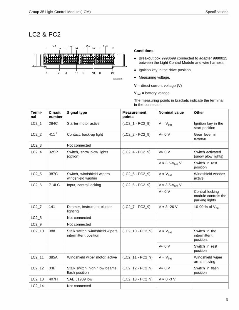
LC2 & PC2
W3005335
Conditions:
• Breakout box 9998699 connected to adapter 9990025between the Light Control Module and wire harness.
• Ignition key in the drive position.
• Measuring voltage.
V = direct current voltage (V)
Vbat = battery voltage
The measuring points in brackets indicate the terminalin the connector.
Termi-nal
Circuitnumber
Signal type Measurementpoints
Nominal value Other
LC2_1 284C Starter motor active (LC2_1 - PC2_9) V ≈ Vbat Ignition key in thestart position
LC2_2 411 1 Contact, back-up light (LC2_2 - PC2_9) V≈ 0 V Gear lever inreverse
LC2_3 Not connected
V≈ 0 V Switch activated(snow plow lights)
LC2_4 32SP Switch, snow plow lights(option)
(LC2_4 - PC2_9)
V ≈ 3.5-Vbat V Switch in restposition
LC2_5 387C Switch, windshield wipers,windshield washer
(LC2_5 - PC2_9) V ≈ Vbat Windshield washeractive
V ≈ 3.5-Vbat VLC2_6 714LC Input, central locking (LC2_6 - PC2_9)
V≈ 0 V Central lockingmodule controls theparking lights
LC2_7 141 Dimmer, instrument clusterlighting
(LC2_7 - PC2_9) V ≈ 3 -26 V 10-90 % of Vbat
LC2_8 Not connected
LC2_9 Not connected
V ≈ Vbat Switch in theintermittentposition.
LC2_10 388 Stalk switch, windshield wipers,intermittent position
(LC2_10 - PC2_9)
V≈ 0 V Switch in restposition
LC2_11 385A Windshield wiper motor, active (LC2_11 - PC2_9) V ≈ Vbat Windshield wiperarms moving
LC2_12 33B Stalk switch, high / low beams,flash position
(LC2_12 - PC2_9) V≈ 0 V Switch in flashposition
LC2_13 407H SAE J1939 low (LC2_13 - PC2_9) V ≈ 0 -3 V
LC2_14 Not connected
5

Group 35 Light Control Module (LCM) Specifications
Termi-nal
Circuitnumber
Signal type Measurementpoints
Nominal value Other
V ≈ 0 V / Vbat(switching)
Warning light activeLC2_15 122A Indicator light, warning light (LC2_15 - PC2_9)
V ≈ 10 -20 V
LC2_16 406H SAE J1939 High (LC2_16 - PC2_9) V ≈ 2 -5 V
LC2_17 400E SAE J1587/J1708 (+) (LC2_17 - PC2_9) V ≈ 2 -5 V
LC2_18 401E SAE J1587/J1708 (-) (LC2_1 8- PC2_9) V ≈ 0 -3 V
PC2_1 35 Fog lights (PC2_1 - PC2_9) V ≈ Vbat LCP in the "Drive+" position and lowbeams activated
PC2_2 1HC Power supply 3 (PC2_2 - PC2_9) V ≈ Vbat
PC2_3 75 Brake light relay, trailer (PC2_3 - PC2_9) V ≈ Vbat Brake lights, active
PC2_4 56F Parking light, tractor, front (PC2_4 - PC2_9) V ≈ Vbat Parking light active
PC2_5 32L Low beam, left (PC2_5 - PC2_9) V ≈ Vbat Low beam active
PC2_6 Not connected
PC2_7 139B Back of cab lights (PC2_7 - PC2_9) V ≈ Vbat Back of cab lights,active
PC2_8 141A Dashboard dimming, backlight (PC2_8 - PC2_9) V ≈ 3 -26 V 10-90 % of Vbat
PC2_9 0XL Ground terminal, control unit (PC2_9 - ground) V≈ 0 V
PC2_10 112C Turn signal light, left, trailer (PC2_10 - PC2_9) V ≈ Vbat / 0 V(switching)
Left turn signal lightactivated
PC2_11 50 Parking light, trailer relay (PC2_11 - PC2_9) V ≈ Vbat Parking light, active
PC2_12 75A Allison retarder indicator (PC2_12 - PC2_9) V ≈ Vbat Retarder active
PC2_13 116 Brake light, tractor (PC2_13 - PC2_9) V ≈ Vbat Brake lights active
PC2_14 53A Marker (ICC) lights, trailer (PC2_14 - PC2_9) V ≈ Vbat Parking light, active
PC2_15 1HD Power supply 5 (PC2_15 - PC2_9) V ≈ Vbat
PC2_16 115 Turn signal light, left, tractor (PC2_16 - PC2_9) V ≈ Vbat / 0 V(switching)
Left turn signal lightactivated
PC2_17 112A Side repeater, left (PC2_17 - PC2_9) V ≈ Vbat / 0 V(switching)
Left turn signal lightactivated
PC2_18 33 Relay, snow plow light (PC2_18 - PC2_9) V ≈ Vbat Snow plow lightactivated
PC2_19 1HB Power supply 2 (PC2_19 - PC2_9) V ≈ Vbat
PC2_20 33R High Beam, right (PC2_20 - PC2_9) V ≈ Vbat high beams active
PC2_21 121 Audible indication, warning light (PC2_21 - PC2_9) V ≈ Vbat Warning lightactivated
1 A113 w/Allison transmission
6

Group 35 Light Control Module (LCM) Specifications
Lighting Control Switch, Signal Descriptions
T3015733
Conditions:
• Breakout box 9998699 with adapter 9813194connected between the Light Control Panel and wireharness.
• Ignition key in the drive position.
• Measuring voltage.
V = direct current voltage (V)
Vbat = battery voltage
The measuring points in brackets indicate the terminalin the connector.
Termi-nal
Circuitnumber
Signal type Measure-ment points
Nominal value Other
V≈ 3.5-Vbat V Position 0 or driving lights1 47 Light switch 1 (1 - 16)
V≈ 0 V Position parking lights orspot lights
V≈ 0 V Position 0 or parkinglights
2 48 Light switch 2 (2 - 16)
V ≈ 3.5-Vbat V Position driving lights orspot lights
3 Not connected
4 Not connected
5 Not connected
6 Not connected
7 Not connected
8 122L Switch, hazard warning lights (8 - 16) V≈ 0 V Button depressed
9 122A Indicator light, warning light (9 - 16) V≈ 6 -9 V Background lighting(30 % of Vbat)
10 Not connected
11 141A Background lighting (11 - 16) V≈ 2 -26 V
12 196L Power supply, instrumentlighting
(12 - 16) V≈ Vbat Ignition power, fuse F65
13 141 Rheostat, instrument lighting (13 - ground) V≈ 2 -26 V
14 Not connected
15 Not connected
16 0XL Ground terminal (16 - ground) V≈ 0 V
7

8

Group 35 Light Control Module (LCM) Tools
Tools
Special tools
9990025 9998699 85104410
Adapter Breakout box Overlay used with adapter 9990025
Other special equipment
J-39200 9813194 85104407
Multimeter Adapter Overlay used with adapter 9813194
9

10

Group 35 Light Control Module (LCM) Troubleshooting
Troubleshooting
MID 216 Light Control Module, Fault CodesMID:Message Identification Description (identification ofcontrol unit).
PID:Parameter Identification Description (identification ofparameter (value)).
PPID:Proprietary Parameter Identification Description (Volvounique identification of parameter (value)).
SID:Subsystem Identification Description (identification ofcomponent).
PSID:Proprietary Subsystem Identification Description(Volvo-unique identification of component).
FMI:Failure Mode Identifier (identification of fault type). See“FMI table” page 13.
For more detailed information concerning thesedesignations, see service information group 0 “VehicleElectronics”.
Fault code 7 Component / function FMI Section
MID 216 SID 240 Program memory 2 “MID 216 SID 240 Program Memory”page 14
MID 216 SID 250 SAE J1587/1708 Information link 2, 3, 4, 9 “MID 216 SID 250 J1587/J1708Information Link” page 15
MID 216 SID 253 Calibration memory, EEPROM 2, 13 “MID 216 SID 253 Calibration MemoryEEPROM” page 16
MID 216 SID 254 Control unit 12 “MID 216 SID 254 Control Unit” page 17
MID 216 PSID 1 High beam, left 5, 6 “MID 216 PSID 1 High Beam (Left Side)”page 18
MID 216 PSID 2 Low beam, left 5, 6 “MID 216 PSID 2 Low Beam (Left Side)”page 19
MID 216 PSID 3 High beam, right 5, 6 “MID 216 PSID 3 High Beam (RightSide)” page 20
MID 216 PSID 4 Low beam, right 5, 6 “MID 216 PSID 4 Low Beam (Right Side)”page 21
MID 216 PSID 5 Fog lights 5, 6 “MID 216 PSID 5 Fog Lights (Front)”page 22
MID 216 PSID 7 Driving lights 5, 6 “MID 216 PSID 7 Driving Lights” page 23
MID 216 PSID 8 Reverse lights 5, 6 “MID 216 PSID 8 Reverse Lights” page24
MID 216 PSID 10 Brake light, left 5, 6 “MID 216 PSID 10 Brake Lights (LeftSide)” page 25
MID 216 PSID 11 Brake light, right 5, 6 “MID 216 PSID 11 Brake Lights (RightSide)” page 26
MID 216 PSID 12 Brake lights, trailer 3, 4 “MID 216 PSID 12 Brake Lights, Trailer”page 27
MID 216 PSID 13 Direction indicator, left front 5, 6 “MID 216 PSID 13 Direction Indicator(Left Front)” page 28
MID 216 PSID 14 Direction indicator, right front 5, 6 “MID 216 PSID 14 Direction Indicator(Right Front)” page 29
MID 216 PSID 17 Direction indicator trailer, left side 5, 6 “MID 216 PSID 17 Direction Indicator,Trailer (Left Side)” page 30
11

Group 35 Light Control Module (LCM) Troubleshooting
Fault code 7 Component / function FMI Section
MID 216 PSID 18 Direction indicator trailer, right side 5, 6 “MID 216 PSID 18 Direction Indicator,Trailer (Right Side)” page 31
MID 216 PSID 19 Relay, intermittent wiper 3, 4 “MID 216 PSID 19 Relay, IntermittentWiper” page 32
MID 216 PSID 20 Dashboard dimming 4 “MID 216 PSID 20 Dash Dimmer Control”page 36
MID 216 PSID 27 Snow plow lights 4 “MID 216 PSID 27 Snow Plow Lights”page 37
MID 216 PSID 28 Hazard sound indication 3 “MID 216 PSID 28 Hazard Alarm” page39
MID 216 PSID 29 Indicator light, warning light 4 “MID 216 PSID 29 Hazard Light Indicator”page 40
MID 216 PSID 30 Light switch, warning light 12 “MID 216 PSID 30 Hazard Light Switch”page 41
MID 216 PSID 33 Stalk switch high/low beam 12 “MID 216 PSID 33 Stalk Switch High/LowBeam” page 53
MID 216 PSID 34 Power supply 1 3, 4 “MID 216 PSID 34 Power Supply 1” page54
MID 216 PSID 35 Power supply 2 3, 4 “MID 216 PSID 35 Power Supply 2” page55
MID 216 PSID 36 Power supply 3 3, 4 “MID 216 PSID 36 Power Supply 3” page56
MID 216 PSID 37 Power supply 4 3, 4 “MID 216 PSID 37 Power Supply 4” page57
MID 216 PSID 38 Power supply 5 3, 4 “MID 216 PSID 38 Power Supply 5” page58
MID 216 PSID 39 Power supply 6 3, 4 “MID 216 PSID 39 Power Supply 6” page59
MID 216 PSID 40 Power supply, ignition key in drivingposition
3 “MID 216 PSID 40 Power Supply, IgnitionON” page 60
MID 216 PSID 41 Stalk switch direction indicator 12 “MID 216 PSID 41 Stalk Switch DirectionIndicator” page 61
MID 216 PSID 42 Rheostat, instrument lighting 3, 4 “MID 216 PSID 42 Rheostat, DashDimmer Control” page 62
MID 216 PSID 45 Side repeater, right 5, 6 “MID 216 PSID 45 Side Repeater (RightSide)” page 63
MID 216 PSID 46 Side repeater, left 5, 6 “MID 216 PSID 46 Side Repeater (LeftSide)” page 64
MID 216 PSID 48 Park and licence plate lights, tractor rear 5, 6 “MID 216 PSID 48 Park and LicensePlate Lights, Tractor” page 65
MID 216 PSID 49 Tractor roof marker/clearance lamps 5, 6 “MID 216 PSID 49 Roof Marker/ClearanceLights, Tractor” page 66
MID 216 PSID 50 Tractor front park lights 5, 6 “MID 216 PSID 50 Park Lights, TractorFront” page 67
MID 216 PSID 51 Trailer park lights 3, 4 “MID 216 PSID 51 Park Lights Relay,Trailer” page 68
MID 216 PSID 52 Allison retarder indicator LED 4 “MID 216 PSID 52 Retarder IndicatorLED” page 69
12

Group 35 Light Control Module (LCM) Troubleshooting
Fault code 7 Component / function FMI Section
MID 216 PSID 53 Marker (ICC) trailer 6 “MID 216 PSID 53 Marker (ICC) TrailerRelay” page 70
MID 216 PSID 54 Marker interrupt 12 “MID 216 PSID 54 Marker Interrupt” page71
MID 216 PSID 55 Headlamp interrupt 12 “MID 216 PSID 55 Headlamp Interrupt”page 72
MID 216 PSID 57 Back of cab lights 5, 6 “MID 216 PSID 57 Back of Cab Lights”page 73
MID 216 PSID 200 SAE J1939 Open-circuit, data link,engine control unit
9 “MID 216 PSID 200 J1939 Data LinkInterruption, Engine ECU” page 74
MID 216 PSID 201 SAE J1939 Open-circuit, data link,vehicle control unit
9 “MID 216 PSID 201 J1939 Data LinkInterruption, Vehicle ECU” page 74
FMI tableFMI Display text SAE text
0 Value too high Data applicable, but above normal operating range.
1 Value too low Data applicable, but below normal operating range.
2 Incorrect data Intermittent or incorrect data.
3 Electrical fault Abnormally high voltage or short-circuit to higher voltage.
4 Electrical fault Abnormally low voltage or short-circuit to lower voltage.
5 Electrical fault Abnormally low current or open-circuit.
6 Electrical fault Abnormally high current or short-circuit to ground.
7 Mechanical fault Incorrect response from the mechanical system.
8 Mechanical or electricalfault
Abnormal frequency.
9 Communication fault Abnormal update rate.
10 Mechanical or electricalfault
Abnormally high variations.
11 Unknown fault Unidentifiable fault.
12 Component fault Defective unit or component.
13 Incorrect calibration Values outside calibration values.
14 Unknown fault Special instructions.
15 Unknown fault Reserved for future use.
13

Group 35 Light Control Module (LCM) Troubleshooting
MID 216 SID 240 Program Memory
T3014623
General informationThe program memory contains rules for the light controlfunctions.
Component: Light Control Module (A27).
Fault code
FMI 2Intermittent or incorrect data.
Conditions for fault code:• If the Light Control Module (LCM) cannot use the
software, the LCM interprets this as an error and afault code is stored.
Possible cause:• Fault during programming.
Noticeable external symptoms:• The LCM is not working.
Appropriate check:• Reprogram the LCM.
14

Group 35 Light Control Module (LCM) Troubleshooting
MID 216 SID 250 J1587/J1708 Information LinkGeneral informationThe SAE J1587/1708 data link is used to communicatewith other control units to share information and functionas a backup in case the J1939 Control data link hasproblems (the engine and brake control units for example).
Component: Light Control Module (A27).
Fault code
FMI 2Intermittent or incorrect data.
Conditions for fault code:• If the Light Control (LCM) cannot interpret information
through the SAE J1587/1708 data link the LCMinterprets this as an error and a fault code is stored.
Possible cause:• Incorrect message.• Interferences with the SAE J1587/1708 Information
link.
Noticeable external symptoms:• Warning light illuminated.
Appropriate check:• Check whether the same fault is present in other
control units.
FMI 3Abnormally high voltage or short-circuit to higher voltage.
Conditions for fault code:• If the Light Control Module (LCM) detects a short-circuit
to power supply in any of the terminals for the SAEJ1587/1708 information link the LCM interprets this asan error and a fault code is stored.
Possible cause:• Short-circuit to power in the wiring harness between
the LCM and other control units.
Noticeable external symptoms:• Warning light illuminated.
Appropriate check:• Checks the voltage on the LCM terminals for the SAE
J1587/1708 information link, see “Lighting ControlModule (LCM), Signal Descriptions” page 3 .
FMI 4Abnormally low voltage or short-circuit to lower voltage.
Conditions for fault code:• If the Light Control Module (LCM) detects a
short-circuit to ground in any of the terminals for theSAE J1587/1708 information link, the LCM interpretsthis as an error and a fault code is stored.
Possible cause:• Short-circuit to ground in the wiring harness between
the LCM and other control units.
Noticeable external symptoms:• Warning light illuminated.
Appropriate check:• Checks the voltage on the LCM terminals for the SAE
J1587/1708 information link, see “Lighting ControlModule (LCM), Signal Descriptions” page 3 .
FMI 9Abnormal update rate.
Conditions for fault code:• If messages do not arrive at the SAE J1587/1708
information link within a reasonable period, the LightControl Module (LCM) interprets this as an error and afault code is stored.
Possible cause:• Open-circuit in the wiring harness between the LCM
and other control units.
Noticeable external symptoms:• Warning light illuminated.
Appropriate check:• Checks the voltage on the LCM terminals for the SAE
J1587/1708 information link, see “Lighting ControlModule (LCM), Signal Descriptions” page 3 .
15

Group 35 Light Control Module (LCM) Troubleshooting
MID 216 SID 253 Calibration Memory EEPROM
T3014623
General informationThe calibration memory is used to store temporary data(fault codes for example).
Component: Light Control Module (A27).
Fault code
FMI 2Intermittent or incorrect data.
Conditions for fault code:• If the checksum in the Light Control Module (LCM)
EEPROM is not correct, the LCM interprets this as anerror and a fault code is stored.
Possible cause:• Fault when programming software, data sets or
parameters.• Fault when storing a fault code.
Noticeable external symptoms:• Warning light illuminated.
Appropriate check:• Reprogram the LCM.
FMI 13Values outside calibration values.
Conditions for fault code:• If the Light Control Module (LCM) EEPROM is empty,
the LCM interprets this as an error and a fault codeis stored.
Possible cause:• Fault when programming software, data sets or
parameters.• Fault when storing a fault code.
Noticeable external symptoms:• Warning light illuminated.
Appropriate check:• Reprogram the LCM.
16

Group 35 Light Control Module (LCM) Troubleshooting
MID 216 SID 254 Control Unit
T3014623
General informationComponent: Light Control Module (A27).
Fault code
FMI 12Defective unit or component.
Conditions for fault code:• If internal checks detect faults a fault code is stored.
Possible cause:• Unknown fault.
Noticeable external symptoms:• Warning light illuminated.• Only parking lights, low beam and warning lights are
illuminated; no lighting control possible.
Appropriate check:• Disconnect the power supply to the Light Control
Module for at least 5 minutes.
17

Group 35 Light Control Module (LCM) Troubleshooting
MID 216 PSID 1 High Beam (Left Side)
W3005553
General informationPower for the left high beam bulb is supplied by a separateterminal in the Light Control Module when high beam isactivated.
Component: Bulb, high beam, left (E01L); Light ControlModule (A27).
Fault code
FMI 5Abnormally low current or open-circuit.
Conditions for fault code:• If the bulbs connected to the left high beam output on
the Light Control Module (LCM) draw less than 2 W(0.1 A), the LCM interprets this as an error and a faultcode is stored.
Possible cause:• Defective bulb.• Open-circuit in the wiring harness between the LCM
and the left high beam bulb.• Open-circuit in the wiring harness between the left high
beam bulb and ground.
Noticeable external symptoms:• Information light illuminated.• Warning light “Bulb failure warning sensor” illuminated.• A message is shown in the display.• Left high beam does not light.
Appropriate check:• Replace left high beam bulb.• Check for an open circuit 33L between the left high
beam bulb and the LCM. Use the wiring diagram. Forthe terminals on the LCM and their nominal values, see“Lighting Control Module (LCM), Signal Descriptions”page 3 .
• Check for an open ground circuit for the left high beambulb. Use the wiring diagram.
FMI 6Abnormally high current or short-circuit to ground.
Conditions for fault code:• If the bulb connected to the left high beam output on
the Light Control Module (LCM) draws more than103 W (8.56A), the LCM interprets this as an error anda fault code is stored.
Note: If the voltage to the LCM is more than 16V a faultcode is not stored.
Possible cause:• Short to ground in the wiring harness between the
LCM and the left high beam bulb.
Noticeable external symptoms:• Information light illuminated.• A message is shown in the display.• Left high beam does not light.
Appropriate check:• Check for a short to ground in circuit 33L between
the left high beam bulb and the LCM. Use the wiringdiagram. For the terminals on the LCM and theirnominal values, see “Lighting Control Module (LCM),Signal Descriptions” page 3 .
18

Group 35 Light Control Module (LCM) Troubleshooting
MID 216 PSID 2 Low Beam (Left Side)
W3005553
General informationPower for the left low beam bulb is supplied by a separateterminal in the Light Control Module when low beam isactivated.
Component: Bulb, low beam, left (E02L); Light ControlModule (A27).
Fault code
FMI 5Abnormally low current or open-circuit.
Conditions for fault code:• If the bulbs connected to the left low beam output on
the Light Control Module (LCM) draw less than 2 W(0.1 A), the LCM interprets this as an error and a faultcode is stored.
Possible cause:• Defective bulb.• Open-circuit in the wiring harness between the LCM
and the left low beam bulb.• Open-circuit in the wiring harness between the left low
beam bulb and ground.
Noticeable external symptoms:• Information light illuminated.• Warning light “Bulb failure warning sensor” illuminated.• A message is shown in the display.• Left low beam does not light.
Appropriate check:• Replace left low beam bulb.• Check for an open circuit 32L between the left low
beam bulb and the LCM. Use the wiring diagram. Forthe terminals on the LCM and their nominal values, see“Lighting Control Module (LCM), Signal Descriptions”page 3 .
• Check for an open ground circuit for the left low beambulb. Use the wiring diagram.
FMI 6Abnormally high current or short-circuit to ground.
Conditions for fault code:• If the bulbs connected to the left low beam output on
the Light Control Module (LCM) draw more than 79 W(6.56 A), the LCM interprets this as an error and a faultcode is stored.
Note: If the voltage to the LCM is more than 16V a faultcode is not stored.
Possible cause:• Short-circuit to ground in the wiring harness between
the LCM and the left low beam bulb.
Noticeable external symptoms:• Information light illuminated.• A message is shown in the display.• Left low beam does not light.
Appropriate check:• Check for a short to ground in circuit 32L between
the left high beam bulb and the LCM. Use the wiringdiagram. For the terminals on the LCM and theirnominal values, see “Lighting Control Module (LCM),Signal Descriptions” page 3 .
19

Group 35 Light Control Module (LCM) Troubleshooting
MID 216 PSID 3 High Beam (Right Side)
W3005553
General informationPower for the right high beam bulb is supplied by aseparate terminal in the Light Control Module when highbeam is activated.
Component: Bulb, high beam, right (E01R); Light ControlModule (A27).
Fault code
FMI 5Abnormally low current or open-circuit.
Conditions for fault code:• If the bulbs connected to the right high beam output on
the Light Control Module (LCM) draw less than 2 W(0.1 A), the LCM interprets this as an error and a faultcode is stored.
Possible cause:• Defective bulb.• Open-circuit in the wiring harness between the LCM
and the right high beam bulb.• Open-circuit in the wiring harness between the right
high beam bulb and ground.
Noticeable external symptoms:• Information light illuminated.• Warning light “Bulb failure warning sensor” illuminated.• A message is shown in the display.• Right high beam does not light.
Appropriate check:• Replace right high beam bulb.• Check for an open circuit 33R between the right high
beam bulb and the LCM. Use the wiring diagram. Forthe terminals on the LCM and their nominal values, see“Lighting Control Module (LCM), Signal Descriptions”page 3 .
• Check for an open ground circuit for the right highbeam bulb. Use the wiring diagram.
FMI 6Abnormally high current or short-circuit to ground.
Conditions for fault code:• If the bulbs connected to the right high beam output on
the Light Control Module (LCM) draw more than 103 W(8.56 A), the LCM interprets this as an error and a faultcode is stored.
Note: If the voltage to the LCM is more than 16V a faultcode is not stored.
Possible cause:• Short-circuit to ground in the wiring harness between
the LCM and the right high beam bulb.
Noticeable external symptoms:• Information light illuminated.• A message is shown in the display.• Right high beam does not light.
Appropriate check:• Check for a short to ground in circuit 33R between
the right high beam bulb and the LCM. Use the wiringdiagram. For the terminals on the LCM and theirnominal values, see “Lighting Control Module (LCM),Signal Descriptions” page 3 .
20

Group 35 Light Control Module (LCM) Troubleshooting
MID 216 PSID 4 Low Beam (Right Side)
W3005553
General informationPower for the right low beam bulb is supplied by aseparate terminal in the Light Control Module when lowbeam is activated.
Component: Bulb, low beam, right (E02R); Light ControlModule (A27).
Fault code
FMI 5Abnormally low current or open-circuit.
Conditions for fault code:• If the bulbs connected to the right low beam output on
the Light Control Module (LCM) draw less than 2 W(0.1 A), the LCM interprets this as an error and a faultcode is stored.
Possible cause:• Defective bulb.• Open-circuit in the wiring harness between the LCM
and the right low beam bulb.• Open-circuit in the wiring harness between the right
low beam bulb and ground.
Noticeable external symptoms:• Information light illuminated.• Warning light “Bulb failure warning sensor” illuminated.• A message is shown in the display.• Right low beam does not light.
Appropriate check:• Replace right low beam bulb.• Check for an open circuit 32R between the right low
beam bulb and the LCM. Use the wiring diagram. Forthe terminals on the LCM and their nominal values, see“Lighting Control Module (LCM), Signal Descriptions”page 3 .
• Check for an open ground circuit for the right low beambulb. Use the wiring diagram.
FMI 6Abnormally high current or short-circuit to ground.
Conditions for fault code:• If the bulbs connected to the right low beam output on
the Light Control Module (LCM) draw more than 79 W(6.56 A), the LCM interprets this as an error and a faultcode is stored.
Note: If the voltage to the LCM is more than 16V a faultcode is not stored.
Possible cause:• Short-circuit to ground in the wiring harness between
the LCM and the right low beam bulb.
Noticeable external symptoms:• Information light illuminated.• A message is shown in the display.• Right low beam does not light.
Appropriate check:• Check for a short to ground in circuit 32R between
the right low beam bulb and the LCM. Use the wiringdiagram. For the terminals on the LCM and theirnominal values, see “Lighting Control Module (LCM),Signal Descriptions” page 3 .
21

Group 35 Light Control Module (LCM) Troubleshooting
MID 216 PSID 5 Fog Lights (Front)
W3005554
General informationPower for the fog lights is supplied by a separate terminalin the Light Control Module when the high beam isactivated and the light switch is in the drive plus position.
Component: Bulb, fog light (E07), Light Control Module(A27).
Fault code
FMI 5Abnormally low current or open-circuit.
Conditions for fault code:• If the bulbs connected to the front fog light output on
the Light Control Module (LCM) draw less than 2 W(0.1 A), the LCM interprets this as an error and a faultcode is stored.
Possible cause:• Both front fog light bulbs defective.• Open-circuit in the wiring harness between the LCM
and both front fog light bulbs.• Open-circuit in the wiring harness between ground and
both front fog light bulbs.
Noticeable external symptoms:• Information light illuminated.• Warning light “Bulb failure warning sensor” illuminated.• A message is shown in the display.• Front fog light does not light.
Appropriate check:• Check both front fog light bulbs.• Check for an open circuit 35 between the front fog light
bulbs and the LCM. Use the wiring diagram. For theterminals on the LCM and their nominal values, see“Lighting Control Module (LCM), Signal Descriptions”page 3 .
• Check for an open ground circuit for both front fog lightbulbs. Use the wiring diagram.
FMI 6Abnormally high current or short-circuit to ground.
Conditions for fault code:• If the bulbs connected to the front fog light output on
the Light Control Module (LCM) draw more than 133 W(11.08 A), the LCM interprets this as an error and afault code is stored.
Note: If the voltage to the control unit is more than 16Va fault code is not stored.
Possible cause:• Short-circuit to ground in the wiring harness between
the LCM and the front fog light bulb.• Too many/powerful bulbs directly connected to the
LCM.
Noticeable external symptoms:• Information light illuminated.• A message is shown in the display.• Front fog light does not light.
Appropriate check:• Check for a short to ground in circuit 35 between
both front fog light bulbs and the LCM. Use the wiringdiagram. For the terminals on the control unit and theirnominal values, see “Lighting Control Module (LCM),Signal Descriptions” page 3 .
22

Group 35 Light Control Module (LCM) Troubleshooting
MID 216 PSID 7 Driving Lights
W3005554
General informationPower for the driving light is supplied by a separateterminal in the Light Control Module (LCM) when the highbeam is activated and the light switch is in the drive plusposition.
Component: Bulb, driving light (E08), Light ControlModule (A27).
Fault code
FMI 5Abnormally low current or open-circuit.
Conditions for fault code:• If the bulbs connected to the driving light output on
the Light Control Module (LCM) draw less than 2 W(0.1 A), the LCM interprets this as an error and a faultcode is stored.
Possible cause:• Both driving lights in the headlight modules defective.• Open-circuit in the wiring harness between the LCM
and both driving lights in the headlight modules.• Open-circuit in the wiring harness between both driving
lights in the headlight modules and ground.
Noticeable external symptoms:• Information light illuminated.• Warning light “Bulb failure warning sensor” illuminated.• A message is shown in the display.• Driving lights in the headlight module not illuminated.
Appropriate check:• Check both driving lights in the headlight module.• Check for an open circuit 37 between both driving
lights and the LCM. Use the wiring diagram. For theterminals on the LCM and their nominal values, see“Lighting Control Module (LCM), Signal Descriptions”page 3 .
• Check for an open ground circuit for both driving lights.Use the wiring diagram.
FMI 6Abnormally high current or short-circuit to ground.
Conditions for fault code:• If the bulbs connected to the driving light output on the
Light Control Module (LCM) draw more than 133 W(11.08 A), the LCM interprets this as an error and afault code is stored.
Note: If the voltage to the LCM is more than 16V a faultcode is not stored.
Possible cause:• Short-circuit to ground in the wiring harness between
the LCM and driving lights.• Too many/powerful bulbs directly connected to the
LCM.
Noticeable external symptoms:• Information light illuminated.• A message is shown in the display.• Driving lights not illuminated.
Appropriate check:• Check for a short to ground in circuit 37 between both
driving lights and the LCM. Use the wiring diagram. Forthe terminals on the LCM and their nominal values, see“Lighting Control Module (LCM), Signal Descriptions”page 3 .
23

Group 35 Light Control Module (LCM) Troubleshooting
MID 216 PSID 8 Reverse Lights
W3005555
General informationPower for the tractor reverse light bulbs is supplied bya separate terminal in the Light Control Module whenreverse gear is selected.
Component: Bulb, reverse light (E06), Light ControlModule (A27), Reversing warning unit, acoustic (H03).
Fault code
FMI 5Abnormally low current or open-circuit.
Conditions for fault code:• If the bulbs connected to the reversing light output on
the Light Control Module (LCM) draw less than 2 W(0.1 A), the LCM interprets this as an error and a faultcode is stored.
Possible cause:• Both reversing light bulbs defective.• Open-circuit in the wiring harness between the LCM
and both reverse light bulbs.• Open-circuit in the wiring harness between both
reverse light bulbs and ground.• Defective acoustic warning device, if installed.
Noticeable external symptoms:• Information light illuminated.• Warning light “Bulb failure warning sensor” illuminated.• A message is shown in the display.• Reverse lights not illuminated.
Appropriate check:• Check both reverse light bulbs.• “3646-06-02-03 Position switch backup (reversing)
lamp, test”.• Check for an open circuit 410 between both reverse
light bulbs and the LCM. Use the wiring diagram. Forthe terminals on the LCM and their nominal values, see“Lighting Control Module (LCM), Signal Descriptions”page 3 .
• Check for an open ground circuit for both reverse lightbulbs. Use the wiring diagram.
FMI 6Abnormally high current or short-circuit to ground.
Conditions for fault code:• If the bulbs connected to the reverse light output on
the Light Control Module (LCM) draw more than 76 W(6.33 A), the LCM interprets this as an error and a faultcode is stored.
Note: If the voltage to the LCM is more than 16V a faultcode is not stored.
Possible cause:• Short-circuit to ground in the wiring harness between
the LCM and reverse light bulb.• Too many/powerful bulbs directly connected to the
LCM.• Defective acoustic warning device, if installed.
Noticeable external symptoms:• Information light illuminated.• A message is shown in the display.• Reverse lights not illuminated.
Appropriate check:• “3646-06-02-03 Position switch backup (reversing)
lamp, test”.• Check for a short to ground in circuit 410 between
the reverse light bulbs and the LCM. Use the wiringdiagram. For the terminals on the LCM and theirnominal values, see “Lighting Control Module (LCM),Signal Descriptions” page 3 .
24

Group 35 Light Control Module (LCM) Troubleshooting
MID 216 PSID 10 Brake Lights (Left Side)
W3005556
General informationPower for the left tractor brake light bulbs is supplied by aseparate terminal in the Light Control Module when thebrakes are applied.
Component: Bulb, brake light (E09), Light Control Module(A27).
Fault code
FMI 5Abnormally low current or open-circuit.
Conditions for fault code:• If the bulbs connected to the left brake light output on
the Light Control Module (LCM) draw less than 2 W(0.1 A), the LCM interprets this as an error and a faultcode is stored.
Possible cause:• Left brake light bulb defective.• Open-circuit in the wiring harness between the LCM
and the left brake light bulb.• Open-circuit in the wiring harness between the left
brake light bulb and ground.
Noticeable external symptoms:• Information light illuminated.• Warning light “Bulb failure warning sensor” illuminated.• A message is shown in the display.• Left brake light does not light.
Appropriate check:• Replace left brake light bulb.• Check for an open circuit 115 between the left brake
light bulb and the LCM. Use the wiring diagram. Forthe terminals on the LCM and their nominal values, see“Lighting Control Module (LCM), Signal Descriptions”page 3 .
• Check for an open ground circuit for the left brake lightbulb. Use the wiring diagram.
FMI 6Abnormally high current or short-circuit to ground.
Conditions for fault code:• If the bulbs connected to the left brake light output on
the Light Control Module (LCM) draw more than 126 W(10.45A), the LCM interprets this as an error and afault code is stored.
Note: If the voltage to the LCM is more than 16V a faultcode is not stored.
Possible cause:• Short-circuit to ground in the wiring harness between
the LCM and the left brake light bulb.• Too many/powerful bulbs directly connected to the
LCM.
Noticeable external symptoms:• Information light illuminated.• A message is shown in the display.• Left brake light does not light.
Appropriate check:• Check for a short to ground in circuit 115 between
the left brake light bulb and the LCM. Use the wiringdiagram. For the terminals on the LCM and theirnominal values, see “Lighting Control Module (LCM),Signal Descriptions” page 3 .
25

Group 35 Light Control Module (LCM) Troubleshooting
MID 216 PSID 11 Brake Lights (Right Side)
W3005556
General informationPower for the right tractor brake light bulbs is suppliedby a separate terminal in the Light Control Module whenthe brakes are applied.
Component: Bulb, brake light (E09), Light Control Module(A27).
Fault code
FMI 5Abnormally low current or open-circuit.
Conditions for fault code:• If the bulbs connected to the right brake light output on
the Light Control Module (LCM) draw less than 2 W(0.1 A), the LCM interprets this as an error and a faultcode is stored.
Possible cause:• Right brake light bulb defective.• Open-circuit in the wiring harness between the LCM
and the right brake light bulb.• Open-circuit in the wiring harness between the right
brake light bulb and ground.
Noticeable external symptoms:• Information light illuminated.• Warning light “Bulb failure warning sensor” illuminated.• A message is shown in the display.• Right brake light does not light.
Appropriate check:• Replace right brake light bulb.• Check for an open circuit 116 between the right brake
light bulb and the LCM. Use the wiring diagram. Forthe terminals on the LCM and their nominal values, see“Lighting Control Module (LCM), Signal Descriptions”page 3 .
• Check for an open ground circuit for the right brakelight bulb. Use the wiring diagram.
FMI 6Abnormally high current or short-circuit to ground.
Conditions for fault code:• If the bulbs connected to the right brake light output on
the Light Control Module (LCM) draw more than 126 W(10.45A), the LCM interprets this as an error and afault code is stored.
Note: If the voltage to the LCM is more than 16V a faultcode is not stored.
Possible cause:• Short-circuit to ground in the wiring harness between
the LCM and the right brake light bulb.• Too many/powerful bulbs directly connected to the
LCM.
Noticeable external symptoms:• Information light illuminated.• A message is shown in the display.• Right brake light does not light.
Appropriate check:• Check for a short to ground in circuit 116 between
the right brake light bulb and the LCM. Use the wiringdiagram. For the terminals on the LCM and theirnominal values, see “Lighting Control Module (LCM),Signal Descriptions” page 3 .
26

Group 35 Light Control Module (LCM) Troubleshooting
MID 216 PSID 12 Brake Lights, Trailer
W3005557
General informationThe trailer brake light output circuit drives the trailer stoprelay (RLY03).
Power for the trailer brake light bulbs is controlled by thetrailer stop relay (RLY03), which is actuated by a separateterminal in the Light Control Module when the brakesare applied.
Note: Fault codes are erased when the trailer isuncoupled.
Note: The fault code is not stored when a bulb isdefective.
Component: Relay, trailer stop (RLY03); Light ControlModule (A27); Trailer connector, 7-pin (X04).
Fault code
FMI 3Voltage above normal or shorted high.
Conditions for fault code:• If the bulbs connected to the trailer brake light output
on the control unit draw less than 2 W (0.1 A), thecontrol unit interprets this as an error and a fault codeis stored.
Possible cause:• Short-circuit to higher voltage in the wiring harness
between the LCM and the trailer brake light relay.• Damaged wire harness.• The trailer brake light relay is defective.
Noticeable external symptoms:• Information light illuminated.• A message is shown in the display.• Trailer brake lights on all the time.
Appropriate check:• Check for a short to battery in circuit 75 between the
LCM and the trailer stop relay (RLY03). Use the wiringdiagram. For the terminals on the control unit and theirnominal values, see “Lighting Control Module (LCM),Signal Descriptions” page 3 .
FMI 4Voltage below normal or shorted low.
Conditions for fault code:• If the bulbs connected to the trailer brake light output
on the control unit draw more than 6 W (0.5 A), thecontrol unit interprets this as an error and a fault codeis stored.
Possible cause:• Short-circuit to ground in the wire harness between the
LCM and trailer brake relay.• Damaged wire harness.
Noticeable external symptoms:• Information light illuminated.• A message is shown in the display.• Trailer brake lights do not light.
Appropriate check:• Check for a short to ground in circuit 75 between the
LCM and the trailer stop relay (RLY03). Use the wiringdiagram. For the terminals on the control unit and theirnominal values, see “Lighting Control Module (LCM),Signal Descriptions” page 3 .
27

Group 35 Light Control Module (LCM) Troubleshooting
MID 216 PSID 13 Direction Indicator (Left Front)
W3005558
General informationPower for the left front tractor turn signal light bulbsis supplied by a separate terminal in the Light ControlModule when the left turn signal light is activated.
Component: Bulb, turn signal light (E13), Light ControlModule (A27).
Fault code
FMI 5Abnormally low current or open-circuit.
Conditions for fault code:• If the bulbs connected to the left front turn signal light
output of the Light Control Module (LCM) draw lessthan 2 W (0.1 A), the LCM interprets this as an errorand a fault code is stored.
Possible cause:• Both left front turn signal light bulbs are defective.• Open-circuit in the wiring harness between the LCM
and both left front turn signal light bulbs.• Open-circuit in the wiring harness between both left
front turn signal light bulbs and ground.
Noticeable external symptoms:• Information light illuminated.• Warning light “Bulb failure warning sensor” illuminated.• A message is shown in the display.• Left front turn signal light does not light.• Indicator light in the instrument cluster flashing at twice
the normal rate.
Appropriate check:• Check both left front turn signal light bulbs.• Check for an open in circuit 112A between the LCM
and the left front turn signal light bulbs. Use the wiringdiagram. For the terminals on the LCM and theirnominal values, see “Lighting Control Module (LCM),Signal Descriptions” page 3 .
• Check for an open ground circuit for the left front turnsignal light bulbs. Use the wiring diagram.
FMI 6Abnormally high current or short-circuit to ground.
Conditions for fault code:• If the bulbs connected to the left front turn signal light
output of the Light Control Module (LCM) draw morethan 36 W (2.99 A), the LCM interprets this as an errorand a fault code is stored.
Note: If the voltage to the LCM is more than 16V a faultcode is not stored.
Possible cause:• Short-circuit to ground in the wiring harness between
the LCM and the left front turn signal light bulb.• Too many/powerful bulbs directly connected to the
LCM.
Noticeable external symptoms:• Information light illuminated.• A message is shown in the display.• Left front turn signal light does not light.
Appropriate check:• Check for a short to ground in circuit 112A between the
LCM and the left front turn signal light bulbs. Use thewiring diagram. For the terminals on the control unitand their nominal values, see “Lighting Control Module(LCM), Signal Descriptions” page 3 .
28

Group 35 Light Control Module (LCM) Troubleshooting
MID 216 PSID 14 Direction Indicator (Right Front)
W3005558
General informationPower for the right front tractor turn signal light bulbsis supplied by a separate terminal in the Light ControlModule when the right turn signal light is activated.
Component: Bulb, turn signal light (E13), Light ControlModule (A27).
Fault code
FMI 5Abnormally low current or open-circuit.
Conditions for fault code:• If the bulbs connected to the right front turn signal light
output of the Light Control Module (LCM) draw lessthan 2 W (0.1 A), the LCM interprets this as an errorand a fault code is stored.
Possible cause:• Both right front turn signal light bulbs are defective.• Open-circuit in the wiring harness between the LCM
and both right front turn signal light bulbs.• Open-circuit in the wiring harness between both right
front turn signal light bulbs and ground.
Noticeable external symptoms:• Information light illuminated.• Warning light “Bulb failure warning sensor” illuminated.• A message is shown in the display.• Right front turn signal light does not light.• Indicator light in the instrument cluster flashing at twice
the normal rate.
Appropriate check:• Check both right front turn signal light bulbs.• Check for an open in circuit 113A between the LCM
and the right front turn signal light bulbs. Use thewiring diagram. For the terminals on the LCM and theirnominal values, see “Lighting Control Module (LCM),Signal Descriptions” page 3 .
• Check for an open ground circuit for the right front turnsignal light bulbs. Use the wiring diagram.
FMI 6Abnormally high current or short-circuit to ground.
Conditions for fault code:• If the bulbs connected to the right front turn signal light
output of the Light Control Module (LCM) draw morethan 36 W (2.99 A), the LCM interprets this as an errorand a fault code is stored.
Note: If the voltage to the LCM is more than 16V a faultcode is not stored.
Possible cause:• Short-circuit to ground in the wiring harness between
the LCM and the right front turn signal light bulb.• Too many/powerful bulbs directly connected to the
LCM.
Noticeable external symptoms:• Information light illuminated.• A message is shown in the display.• Right front turn signal light does not light.
Appropriate check:• Check for a short to ground in circuit 113A between the
LCM and the right front turn signal light bulbs. Use thewiring diagram. For the terminals on the control unitand their nominal values, see “Lighting Control Module(LCM), Signal Descriptions” page 3 .
29

Group 35 Light Control Module (LCM) Troubleshooting
MID 216 PSID 17 Direction Indicator, Trailer (Left Side)
W3005559
General informationPower for the left trailer turn signal light bulbs is suppliedby a separate terminal in the Light Control Module whenthe left turn signal light is activated.
Note: Fault codes are erased when the trailer isuncoupled.
Note: The fault code is not stored when a bulb isdefective.
Component: Light Control Module (A27); Trailerconnector, 7-pin (X04).
Fault code
FMI 5Abnormally low current or open-circuit.
Conditions for fault code:• If the bulbs connected to the left trailer turn signal light
output on the Light Control Module (LCM) draw lessthan 2 W (0.1 A), the LCM interprets this as an errorand a fault code is stored.
Possible cause:
• Left trailer turn signal light bulbs are defective.• Open-circuit in the wiring harness between the LCM
and the left trailer turn signal light bulbs.• Open-circuit in the wiring harness between the left
trailer turn signal light bulbs and ground.
Noticeable external symptoms:• Information light illuminated.• Warning light “Bulb failure warning sensor” illuminated.• A message is shown in the display.• Left trailer turn signal light does not light.
Appropriate check:• Check the left trailer turn signal light bulbs.• Check for an open in circuit 112C between the LCM
and the left trailer turn signal light bulbs. Use thewiring diagram. For the terminals on the LCM and theirnominal values, see “Lighting Control Module (LCM),Signal Descriptions” page 3 .
• Check for an open ground circuit for the left trailer turnsignal light bulbs. Use the wiring diagram.
FMI 6Abnormally high current or short-circuit to ground.
Conditions for fault code:• If the bulbs connected to the left trailer turn signal light
output on the Light Control Module (LCM) draw morethan 225 W (18.7 A), the LCM interprets this as anerror and a fault code is stored.
Note: If the voltage to the LCM is more than 16V a faultcode is not stored.
Possible cause:• Short-circuit to ground in the wiring harness between
the LCM and the left trailer turn signal light bulbs.• Too many/powerful bulbs directly connected to the
LCM.
Noticeable external symptoms:• Information light illuminated.• A message is shown in the display.• Left trailer turn signal light does not light.
Appropriate check:• Check for a short to ground in circuit 112C between the
LCM and the left trailer turn signal light bulbs. Use thewiring diagram. For the terminals on the control unitand their nominal values, see “Lighting Control Module(LCM), Signal Descriptions” page 3 .
30

Group 35 Light Control Module (LCM) Troubleshooting
MID 216 PSID 18 Direction Indicator, Trailer (Right Side)
W3005559
General informationPower for the right trailer turn signal light bulbs is suppliedby a separate terminal in the Light Control Module whenthe right turn signal light is activated.
Note: Fault codes are erased when the trailer isuncoupled.
Note: The fault code is not stored when a bulb isdefective.
Component: Light Control Module (A27); Trailerconnector, 7-pin (X04).
Fault code
FMI 5Abnormally low current or open-circuit.
Conditions for fault code:• If the bulbs connected to the right trailer turn signal
light output on the Light Control Module (LCM) drawless than 2 W (0.1 A), the LCM interprets this as anerror and a fault code is stored.
Possible cause:
• Open-circuit in the wiring harness between the LCMand the right trailer turn signal light bulbs.
• Open-circuit in the wiring harness between the righttrailer turn signal light bulbs and ground.
• Right trailer turn signal light bulbs are defective.
Noticeable external symptoms:• Information light illuminated.• Warning light “Bulb failure warning sensor” illuminated.• A message is shown in the display.• Right trailer turn signal light does not light.
Appropriate check:• Check the left trailer turn signal light bulbs.• Check for an open in circuit 113C between the LCM
and the right trailer turn signal light bulbs. Use thewiring diagram. For the terminals on the LCM and theirnominal values, see “Lighting Control Module (LCM),Signal Descriptions” page 3 .
• Check for an open ground circuit for the right trailerturn signal light bulbs. Use the wiring diagram.
FMI 6Abnormally high current or short-circuit to ground.
Conditions for fault code:• If the bulbs connected to the right trailer turn signal
light output on the Light Control Module (LCM) drawmore than 225 W (18.7 A), the LCM interprets this asan error and a fault code is stored.
Note: If the voltage to the LCM is more than 16V a faultcode is not stored.
Possible cause:• Short-circuit to ground in the wiring harness between
the LCM and the right trailer turn signal light bulbs.• Too many/powerful bulbs directly connected to the
LCM.
Noticeable external symptoms:• Information light illuminated.• A message is shown in the display.• Right trailer turn signal light does not light.
Appropriate check:• Check for a short to ground in circuit 113C between the
LCM and the right trailer turn signal light bulbs. Usethe wiring diagram. For the terminals on the controlunit and their nominal values, see “Lighting ControlModule (LCM), Signal Descriptions” page 3 .
31

Group 35 Light Control Module (LCM) Troubleshooting
MID 216 PSID 19 Relay, Intermittent Wiper
W3005560
General informationThe Light Control Module (LCM) controls the windshieldwiper intermittent function and the wiping combined withwindshield washer function.
The LCM receives a signal when the windshield wiperswitch is in the washer or intermittent positions. The signalis transmitted by the windshield wiper switch. When theLCM logic activates the windshield wipers, the intermittentwiper relay is grounded through terminal PC1_14. Theintermittent wiper relay supplies power to the windshieldwiper motor through the windshield wiper switch.
Component: Relay, intermittent wiper (RLY12); LightControl Module (A27); Fuse (F26); Windshield wiperswitch (S06); Windshield wiper motor (M01); Windshieldwasher pump (M02).
Fault code
FMI 3Abnormally high voltage or short-circuit to higher voltage.
Conditions for fault code:• If the voltage at the output on the Light Control Module
(LCM) for the intermittent wiper relay is more than 1.0Vwhen the LCM activates the relay, the LCM interpretsthis as an error and a fault code is stored.
Possible cause:• Open-circuit in the wiring harness between the LCM
and the intermittent wiper relay.
Noticeable external symptoms:• Information light illuminated.• A message is shown in the display.• Intermittent wiping, and wiping combined with
windshield washer do not function.
Note: Constant wiping still functions.
Appropriate check:• “MID 216 PSID 19 Relay, Intermittent Wiper, Check”
page 33.
FMI 4Abnormally low voltage or short-circuit to ground.
Conditions for fault code:• If the voltage at the terminal on the Light Control
Module (LCM) for the intermittent wiper relay is lessthan 1.2V when the relay should be inactive, the LCMinterprets this as an error and a fault code is stored.
Possible cause:• Short-circuit to ground in the wiring harness between
the LCM and intermittent wiper relay.
Noticeable external symptoms:• Information light illuminated.• A message is shown in the display.• The windshield wipers run constantly.
Appropriate check:• “MID 216 PSID 19 Relay, Intermittent Wiper, Check”
page 33.
32

Group 35 Light Control Module (LCM) Troubleshooting
3500-21-02-01MID 216 PSID 19 Relay, Intermittent Wiper, Check
You must read and understand the precautions andguidelines in Service Information, group 30, "GeneralSafety Practices", before performing this procedure.If you are not properly trained and certified in thisprocedure, ask your supervisor for training beforeyou perform it.
Special tools: 9998699, 9990025Other special equipment: J-39200
NOTE• During fault-tracing check the relevant connectors.
Check for loose connections, contact resistanceand oxidation. For a more detailed description offault-tracing cables and connectors, see serviceinformation group 371.
• Do not use the chassis as a ground when takingreadings. Use the door stop or ground plate in therear combined light.
Appropriate tests in the PC toolThe following tests are useful for a closer examination ofthe component function:
• “3630-08–02–01 Intermittent Wiper, test”
Measurement at control unit1
Conditions:
• Adapter 9990025 with breakout box 9998699 betweenthe Light Control Module and wiring harness connectorPC1 (brown 21 pin connector).
• Measuring voltage using the multimeter.
• Ignition key in the drive position.
• Windshield wipers in rest position
Measuring points Nominal value
PC1_14 - PC1_21 V ≈ Vbat
9998699 , 9990025J-39200
33

Group 35 Light Control Module (LCM) Troubleshooting
2
Conditions:
• Adapter 9990025 with breakout box 9998699 betweenthe Light Control Module and wiring harness connectorPC1 (brown 21 pin connector).
• Measuring voltage using the multimeter.
• Ignition key in the drive position.
• Windshield wipers moving.
•Note: The terminal is supplied with power for a shortperiod during activation. Use the “Min Max” functionon the multimeter and check that the “Min” voltagesis correct.
Measuring points Nominal value
PC1_14 - PC1_21 V ≈ 0V
9998699 , 9990025J-39200
Measurement at component (wiperrelay)1
Conditions:
• Measuring voltage using the multimeter.
• Ignition key in the drive position.
• Windshield wiper stalk switch in rest position.
Measuring points at thewiper relay
Nominal value
85–Ground V ≈ Vbat
J-39200
34

Group 35 Light Control Module (LCM) Troubleshooting
2
Conditions:
• Measuring voltage using the multimeter.
• Ignition key in the drive position.
• Windshield wipers activated by Light Control Module.
Note: The terminal is supplied with power for a shortperiod during activation. Use the “Min Max” functionon the multimeter and check that the “Min” voltagesis correct.
Measuring points at thewiper relay
Nominal value
85–Ground V ≈ 0 V
J-39200
VerificationCheck that the error has been corrected by checking thewindshield wiper function or by using the tester in VCADSPro (see “Appropriate tests in the PC tool” page 33).
35

Group 35 Light Control Module (LCM) Troubleshooting
MID 216 PSID 20 Dash Dimmer Control
W3005269
W3005721
General informationThe Light Control Module (LCM) controls the instrumentpanel lamps dimmer function.
Component: Light switch (S01), Light Control Module(A27).
Fault code
FMI 4Abnormally low voltage or short-circuit to lower voltage.
Conditions for fault code:• If the Light Control Module (LCM) detects a short-circuit
to ground, the LCM interprets this as an error and afault code is stored.
Possible cause:• Open-circuit in the power supply in the wiring harness
between the LCM and dashboard lights.• Open-circuit in the wiring harness between the LCM
and the dashboard lights.• Short-circuit to ground in the wiring harness between
the LCM and dashboard lights.• Contact resistance or oxidation.
Note: If by chance the dimmer control is not functioning,check fuse (F65) for being blown/missing. This fusesupplies the light switch with power for instrument lighting.
Noticeable external symptoms:• Information light illuminated.
Appropriate check:• “MID 216 PSID 29/30/42 Lighting Control Switch,
Check” page 42.
36

Group 35 Light Control Module (LCM) Troubleshooting
MID 216 PSID 27 Snow Plow Lights
W3006786
General informationWhen switching the snow plow switch the LCM turns offhigh and low beam headlamps, driving and fog lights. TheLCM activates the snow plough relay output in case offlash to pass or high beam is activated and drive the highbeam headlights by a relay. Interrupter functions have noinfluence on this function.
Component: Snow Plow Lamps Fuse RH (F35), SnowPlow Lamps Fuse LH (F33), Snow Plow Lamp Switch(S12), Snow Plow LCM Input Relay (RLY28), Snow plow,RH relay (RLY27), Snow plow, LH relay (RLY26), LightControl Module (A27), Snow Plow Lamp (E31L), SnowPlow Lamp (E31R).
37

Group 35 Light Control Module (LCM) Troubleshooting
Fault code
FMI 4Abnormally low voltage or short-circuit to ground.
Conditions for fault code:• If the voltage at the terminal on the Light Control
Module (LCM) for the snow plow lights relay is lessthan 1.2V when the relay should be active, the LCMinterprets this as an error and a fault code is stored.
Possible cause:• Short-circuit to ground in the wiring harness between
the LCM and snow plow lights relay.
Noticeable external symptoms:• Information light illuminated.• A message is shown in the display.• The snow plow lights on constantly.
Appropriate check:• Check for an short to ground in circuit 33 between the
LCM and left/right snow plow high beam relay (RLY26/27). Use the wiring diagram. For the terminalson the LCM and their nominal values, see “LightingControl Module (LCM), Signal Descriptions” page 3 .
38

Group 35 Light Control Module (LCM) Troubleshooting
MID 216 PSID 28 Hazard Alarm
W3005563
General informationDuring activation of the hazard function the LCM shallindicate to the cluster a hazard sound indication. Thisis done by pulsing PC2-21 high and low with the samefrequency as the external loads. High level means activeloads and low level means inactive loads.
Component: Light Control Module (A27), InstrumentCluster (A03).
Fault code
FMI 3Abnormally high voltage or short-circuit to higher voltage.
Conditions for fault code:• If the buzzer, in the dash, connected to the hazard
sound indication output on the Light Control Module(LCM) draws less than 0.5 A, the LCM interprets thisas an error and a fault code is stored.
Possible cause:• Open-circuit in the cable harness between the LCM
and dash cluster.• Instrument cluster input from the LCM is defective.
Noticeable external symptoms:• Information light illuminated.• A message is shown in the display.• Hazard sound buzzer does not work.• No cluster wake-up when hazard is activated.
Appropriate check:• Check for an open in circuit 121 between the LCM and
dash cluster. Use the wiring diagram. For the terminalson the LCM and their nominal values, see “LightingControl Module (LCM), Signal Descriptions” page 3 .
39

Group 35 Light Control Module (LCM) Troubleshooting
MID 216 PSID 29 Hazard Light Indicator
W3005269
W3006789
General informationThe warning indicator light in the light control panel isactivated by the Light Control Module when the hazardswitch is depressed.
Component: Light switch (S01), Light Control Module(A27).
Fault code
FMI 4Abnormally low voltage or short-circuit to lower voltage.
Conditions for fault code:• If the warning light indicator light draws more than 2 W
(0.5 A), the Light Control Module (LCM) interprets thisas an error and a fault code is stored.
Possible cause:• Short-circuit to ground in the wiring harness between
the light control module and the main lighting switch.
Noticeable external symptoms:• Information light illuminated.• Warning light indicator does not light.
Appropriate check:• “3646-06-02-01 Switch lamp, test”.• “MID 216 PSID 29/30/42 Lighting Control Switch,
Check” page 42.
40

Group 35 Light Control Module (LCM) Troubleshooting
MID 216 PSID 30 Hazard Light Switch
W3005269
W3006789
General informationThe light switch controls which outer lighting should beilluminated. When the warning light switch is depressed,power is supplied to an input on the control unit which inturn activates the warning light.
Component: Light switch (S01), Light Control Module(A27).
Fault code
FMI 12Defective unit or component.
Conditions for fault code:• If the warning light switch is held in for more than
60 seconds the control unit interprets this as an errorand a fault code is stored.
Possible cause:• User error.• Defective light switch.• Short-circuit to ground in the cable harness between
the control unit and switch.
Noticeable external symptoms:• Information light illuminated.• The warning light goes out after 60 seconds.
Appropriate check:• “3646-06-02-01 Switch lamp, test”.• “MID 216 PSID 29/30/42 Lighting Control Switch,
Check” page 42.
41

Group 35 Light Control Module (LCM) Troubleshooting
3500-21-03-02MID 216 PSID 29/30/42 Lighting Control Switch, Check
You must read and understand the precautions andguidelines in Service Information, group 30, "GeneralSafety Practices", before performing this procedure.If you are not properly trained and certified in thisprocedure, ask your supervisor for training beforeyou perform it.
Special tools: 9998699, 9990025Other special equipment: J-39200, 9813194
NOTE• During fault-tracing check the relevant connectors.
Check for loose connections, contact resistanceand oxidation. For a more detailed description offault-tracing cables and connectors, see serviceinformation group 371.
• Do not use the chassis as a ground when takingreadings. Use the door stop or ground plate in thedistribution box.
Appropriate tests in the PC toolThe following tests are useful for a closer examination ofthe component function:
• “3646-06-02-01 Switch lamp, test”.
Measurement at the componentbetween the component and thecontrol unit
Position 0
1
Conditions:
• Adapter 9813194 with breakout box 9998699 betweenthe light switch and cable harness.
• Measuring voltage using the multimeter.
• Ignition key in the drive position.
• Light switch in position 0.
Measuring points Nominal value
1–16 V ≈ 3.5–16 V
2–16 V ≈ 0 V
9998699 9813194, J-39200
42

Group 35 Light Control Module (LCM) Troubleshooting
Position parking lights
2
Conditions:
• Adapter 9813194 with breakout box 9998699 betweenthe light switch and cable harness.
• Measuring voltage using the multimeter.
• Ignition key in the drive position.
• Light switch in the parking light position .
Measuring points Nominal value
1–16 V ≈ 0 V
2–16 V ≈ 0 V
9998699 9813194, J-39200
Drive position
3
Conditions:
• Adapter 9813194 with breakout box 9998699 betweenthe light switch and cable harness.
• Measuring voltage using the multimeter.
• Ignition key in the drive position.
• Light switch in the Drive position .
Measuring points Nominal value
1–16 V ≈ 3.5–16 V
2–16 V ≈ 3.5–16 V
9998699 9813194, J-39200
43

Group 35 Light Control Module (LCM) Troubleshooting
Drive plus position
4
Conditions:
• Adapter 9813194 with breakout box 9998699 betweenthe light switch and cable harness.
• Measuring voltage using the multimeter.
• Ignition key in the drive position.
• Light switch in the Drive plus position .
Measuring points Nominal value
1–16 V ≈ 0 V
2–16 V ≈ 3.5–16 V
9998699 9813194, J-39200
Hazard warning lights
5
Conditions:
• Adapter 9813194 with breakout box 9998699 betweenthe light switch and cable harness.
• Measuring voltage using the multimeter.
• Ignition key in the drive position.
• Warning light switch depressed.
Measuring points Nominal value
8–16 V ≈ 0 V
9–16 V ≈ Vbat / 0 V (Switching)V ≈ 6–9 V (Backgroundlighting)
9998699 9813194, J-39200
44

Group 35 Light Control Module (LCM) Troubleshooting
Rheostat, Instrument Cluster Lighting
6
Conditions:
• Adapter 9813194 with breakout box 9998699connected to the light switch.
• Measuring voltage using the multimeter.
• Ignition key in the drive position.
• Light switch in the driving lights position.
Measuring points Nominal value
12–16 V ≈ Vbat (12V input)
13–16 V ≈ 2–16 V (Rotate thumbwheel control)
9998699 9813194, J-39200
Background lighting (dashswitches/components, etc.)
7
Conditions:
• Adapter 9813194 with breakout box 9998699connected to the light switch.
• Measuring voltage using the multimeter.
• Ignition key in the drive position.
• Light switch in the driving lights position .
Measuring points Nominal value
11–16 V ≈ 4–16 V (Rotate thumbwheel control)
9998699 9813194, J-39200
45

Group 35 Light Control Module (LCM) Troubleshooting
Checking component
Position 0
8
Conditions:
• Adapter 9813194 with breakout box 9998699connected to the light switch.
• Cable harness disconnected.
• Measuring resistance using a multimeter.
• Ignition key in off position.
• Light switch in position 0.
Measuring points Nominal value
1–16 R ≈ O.L.
2–16 R ≈ 0
9998699 9813194, J-39200
Position parking lights
9
Conditions:
• Adapter 9813194 with breakout box 9998699connected to the light switch.
• Cable harness disconnected.
• Measuring resistance using a multimeter.
• Ignition key in off position.
• Light switch in the parking light position .
Measuring points Nominal value
1–16 R ≈ 0
2–16 R ≈ 0
9998699 9813194, J-39200
46

Group 35 Light Control Module (LCM) Troubleshooting
Drive position
10
Conditions:
• Adapter 9813194 with breakout box 9998699connected to the light switch.
• Cable harness disconnected.
• Measuring resistance using a multimeter.
• Ignition key in off position.
• Light switch in the Drive position .
Measuring points Nominal value
1–16 R ≈ O.L.
2–16 R ≈ O.L.
9998699 9813194, J-39200
Drive plus position
11
Conditions:
• Adapter 9813194 with breakout box 9998699connected to the light switch.
• Cable harness disconnected.
• Measuring resistance using a multimeter.
• Ignition key in off position.
• Light switch in the Drive plus position .
Measuring points Nominal value
1–16 R ≈ 0
2–16 R ≈ O.L.
9998699 9813194, J-39200
47

Group 35 Light Control Module (LCM) Troubleshooting
Hazard warning lights
12
Conditions:
• Adapter 9813194 with breakout box 9998699connected to the light switch.
• Cable harness disconnected.
• Measuring resistance using a multimeter.
• Ignition key in off position.
• Warning light switch depressed.
Measuring points Nominal value
8–16 R ≈ 0
9998699 , 9813194J-39200
Rheostat, instrument cluster lighting
13
Conditions:
• Adapter 9813194 with breakout box 9998699connected to the light switch.
• Cable harness disconnected.
• Measuring resistance using a multimeter.
• Ignition key in off position.
Measuring points Nominal value
12–16 R ≈ 5.0 k
13–16 R ≈ 0.5–5.0 k
9998699 , 9813194J-39200
48

Group 35 Light Control Module (LCM) Troubleshooting
Checking sub-systems
Position 0
14
Conditions:
• Adapter 9990025 with breakout box 9998699 betweenthe Light Control Module and wiring harness connectorPC1 and LC1.
• Measuring voltage using the multimeter.
• Ignition key in the drive position.
• Light switch in position 0.
Measuring points Nominal value
LC1_4 - PC1_21 V ≈ 0 V
LC1_10 - PC1_21 V ≈ 3.5-16 V
9998699 , 9990025J-39200
Position parking lights
15
Conditions:
• Adapter 9990025 with breakout box 9998699 betweenthe Light Control Module and wiring harness connectorPC1 and LC1.
• Measuring voltage using the multimeter.
• Ignition key in the drive position.
• Light switch in the parking light position .
Measuring points Nominal value
LC1_4 - PC1_21 V ≈ 0 V
LC1_10 - PC1_21 V ≈ 0 V
9998699 , 9990025J-39200
49

Group 35 Light Control Module (LCM) Troubleshooting
Drive position
16
Conditions:
• Adapter 9990025 with breakout box 9998699 betweenthe Light Control Module and wiring harness connectorPC1 and LC1.
• Measuring voltage using the multimeter.
• Ignition key in the drive position.
• Light switch in the Drive position .
Measuring points Nominal value
LC1_4 - PC1_21 V ≈ 3.5-16 V
LC1_10 - PC1_21 V ≈ 3.5-16 V
9998699 , 9990025J-39200
Drive plus position
17
Conditions:
• Adapter 9990025 with breakout box 9998699 betweenthe Light Control Module and wiring harness connectorPC1 and LC1.
• Measuring voltage using the multimeter.
• Ignition key in the drive position.
• Light switch in the Drive plus position .
Measuring points Nominal value
LC1_4 - PC1_21 V ≈ 3.5-16 V
LC1_10 - PC1_21 V ≈ 0 V
9998699 , 9990025J-39200
50

Group 35 Light Control Module (LCM) Troubleshooting
Hazard warning lights
18
Conditions:
• Adapter 9990025 with breakout box 9998699 betweenthe Light Control Module and wiring harness connectorPC1 and LC1 or PC2 and LC2.
• Measuring voltage using the multimeter.
• Ignition key in the drive position.
• Warning light switch depressed.
Measuring points Nominal value
LC1_11 - PC1_21 V ≈ 0 V
LC2_15 - PC2_9 V ≈ Vbat (Flashing)
9998699 , 9990025J-39200
Rheostat, instrument cluster lighting
19
Conditions:
• Adapter 9990025 with breakout box 9998699 betweenthe Light Control Module and wiring harness connectorPC2 and LC2.
• Measuring voltage using the multimeter.
• Ignition key in the drive position.
Measuring points Nominal value
LC2_7 - PC2_9 V ≈ 2-16 V
9998699 , 9990025J-39200
51

Group 35 Light Control Module (LCM) Troubleshooting
Background lighting (dashswitches/components, etc.)
20
Conditions:
• Adapter 9990025 with breakout box 9998699 betweenthe Light Control Module and wiring harness connectorPC2.
• Measuring voltage using the multimeter.
• Ignition key in the drive position.
Measuring points Nominal value
PC2_12 - PC2_9 V ≈ 4-16 V
9998699 , 9990025J-39200
VerificationCheck that the error has been remedied using the tester inPC tool (see “Appropriate tests in the PC tool” page 42).
52

Group 35 Light Control Module (LCM) Troubleshooting
MID 216 PSID 33 Stalk Switch High/Low Beam
W3005565
General informationThe high/low beam stalk switch supplies power to an inputon the light control module when switching between highand low beam.
Component: Stalk switch, high/low beam (S13), LightControl Module (A27).
Fault code
FMI 12Defective unit or component.
Conditions for fault code:• If the high/low beam switch is held in the switching
position (grounded) for more than 60 seconds the LightControl Module (LCM) interprets this as an error and afault code is stored.
Possible cause:• User error.• Defective switch.• Short-circuit to ground in the cable harness between
the LCM and bulb.
Noticeable external symptoms:• Information light illuminated.• High beam goes out after 60 seconds, low beam
remains illuminated.
Appropriate check:• “3646-06-02-04 Lever switch high beam/low beam,
test”• Fault-trace the cable harness for a short-circuit to
ground between the control unit and the switch. Usethe wiring diagram. For the terminals on the LCM andtheir nominal values, see “Lighting Control Module(LCM), Signal Descriptions” page 3 .
53

Group 35 Light Control Module (LCM) Troubleshooting
MID 216 PSID 34 Power Supply 1
W3006787
Note: 30A circuit breakers are installed in thefollowing fuse locations: F8, F10, F16, F42, F45and F49.
General informationThe Light control Module (LCM) is powered at all timesby six main power supply pins and is activated by theignition switch, also whenever any wake up functions areactivated. Each of the six pins supports various lampfunctions.
Note: The fault code is stored for one power supply at atime. If there are faults in several power supplies at thesame time the active fault code must be corrected beforethe next one can be read off/checked.
Power supply 1 is protected by a 30A circuit breaker.
Component: LCM1, Circuit Breaker (F8); Light ControlModule (A27).
Fault code
FMI 3Abnormally high voltage or short-circuit to higher voltage.
Conditions for fault code:• If the voltage at the power supply 1 (PC1-9) input on
the Light Control Module (LCM) is more than 16V,the LCM interprets this as an error and a fault codeis stored.
Possible cause:• Alternator fault.• Jump starting has been used.
Noticeable external symptoms:• Information light illuminated.• Lighting does not function.
Appropriate check:• Check whether other control units have power supply
fault codes. If so perform a charging test on the vehicleto see if the high voltage is due to battery or alternatorproblems.
FMI 4Abnormally low voltage or short-circuit to lower voltage.
Conditions for fault code:• If the voltage at the power supply 1 (PC1-9) input on the
Light Control Module (LCM) is less than 8V, the LCMinterprets this as an error and a fault code is stored.
Possible cause:• Open circuit breaker (F8).• Open-circuit in the wiring harness between the
fuse/relay center and the LCM.• Short-circuit to ground in the wiring harness between
the fuse/relay center and LCM.• Low battery voltage.
Noticeable external symptoms:• Information light illuminated.• Certain bulbs do not operate.
Appropriate check:• Check battery voltage.• Fault-trace the power supply for an open-circuit or
short-circuit to ground between the fuse/relay centerand LCM. Use the wiring diagram. For the terminals onthe control unit and their nominal values, see “LightingControl Module (LCM), Signal Descriptions” page 3 .
54

Group 35 Light Control Module (LCM) Troubleshooting
MID 216 PSID 35 Power Supply 2
W3006787
Note: 30A circuit breakers are installed in thefollowing fuse locations: F8, F10, F16, F42, F45and F49.
General informationThe Light control Module (LCM) is powered at all timesby six main power supply pins and is activated by theignition switch, also whenever any wake up functions areactivated. Each of the six pins supports various lampfunctions.
Note: The fault code is stored for one power supply at atime. If there are faults in several power supplies at thesame time the active fault code must be corrected beforethe next one can be read off/checked.
Power supply 2 (PC2:19) is protected by a 30A circuitbreaker.
Component: LCM2, Circuit Breaker (F10); Light ControlModule (A27).
Fault code
FMI 3Abnormally high voltage or short-circuit to higher voltage.
Conditions for fault code:• If the voltage at the power supply 2 (PC2:19) input
on the Light Control Module (LCM) is more than 16V,the LCM interprets this as an error and a fault codeis stored.
Possible cause:• Alternator fault.• Jump starting has been used.
Noticeable external symptoms:• Information light illuminated.• Lighting does not function.
Appropriate check:• Check whether other control units have power supply
fault codes. If so perform a charging test on the vehicleto see if the high voltage is due to battery or alternatorproblems.
FMI 4Abnormally low voltage or short-circuit to lower voltage.
Conditions for fault code:• If the voltage at the power supply 2 (PC2:19) input
on the Light Control Module (LCM) is less than 8V,the LCM interprets this as an error and a fault codeis stored.
Possible cause:• Open circuit breaker (F10).• Open-circuit in the wiring harness between the
fuse/relay center and the LCM.• Short-circuit to ground in the wiring harness between
the fuse/relay center and LCM.• Low battery voltage.
Noticeable external symptoms:• Information light illuminated.• Certain bulbs do not operate.
Appropriate check:• Check battery voltage.• Fault-trace the power supply for an open-circuit or
short-circuit to ground between the fuse/relay centerand LCM. Use the wiring diagram. For the terminals onthe control unit and their nominal values, see “LightingControl Module (LCM), Signal Descriptions” page 3 .
55

Group 35 Light Control Module (LCM) Troubleshooting
MID 216 PSID 36 Power Supply 3
W3006787
Note: 30A circuit breakers are installed in thefollowing fuse locations: F8, F10, F16, F42, F45and F49.
General informationThe Light control Module (LCM) is powered at all timesby six main power supply pins and is activated by theignition switch, also whenever any wake up functions areactivated. Each of the six pins supports various lampfunctions.
Note: The fault code is stored for one power supply at atime. If there are faults in several power supplies at thesame time the active fault code must be corrected beforethe next one can be read off/checked.
Power supply 3 (PC2:2) is protected by a 30A circuitbreaker.
Component: LCM3, circuit breaker (F16); Light ControlModule (A27).
Fault code
FMI 3Abnormally high voltage or short-circuit to higher voltage.
Conditions for fault code:• If the voltage at the power supply 3 (PC2:2) input on the
Light Control Module (LCM) is more than 16V, the LCMinterprets this as an error and a fault code is stored.
Possible cause:• Alternator fault.• Jump starting has been used.
Noticeable external symptoms:• Information light illuminated.• Lighting does not function.
Appropriate check:• Check whether other control units have power supply
fault codes. If so perform a charging test on the vehicleto see if the high voltage is due to battery or alternatorproblems.
FMI 4Abnormally low voltage or short-circuit to lower voltage.
Conditions for fault code:• If the voltage at the power supply 3 (PC2:2) input on the
Light Control Module (LCM) is less than 8 V, the LCMinterprets this as an error and a fault code is stored.
Possible cause:• Open circuit breaker (F16).• Open-circuit in the wiring harness between the
fuse/relay center and the LCM.• Short-circuit to ground in the wiring harness between
the fuse/relay center and LCM.• Low battery voltage.
Noticeable external symptoms:• Information light illuminated.• Certain bulbs do not operate.
Appropriate check:• Check battery voltage.• Fault-trace the power supply for an open-circuit or
short-circuit to ground between the fuse/relay centerand LCM. Use the wiring diagram. For the terminals onthe control unit and their nominal values, see “LightingControl Module (LCM), Signal Descriptions” page 3 .
56

Group 35 Light Control Module (LCM) Troubleshooting
MID 216 PSID 37 Power Supply 4
W3006787
Note: 30A circuit breakers are installed in thefollowing fuse locations: F8, F10, F16, F42, F45and F49.
General informationThe Light control Module (LCM) is powered at all timesby six main power supply pins and is activated by theignition switch, also whenever any wake up functions areactivated. Each of the six pins supports various lampfunctions.
Note: The fault code is stored for one power supply at atime. If there are faults in several power supplies at thesame time the active fault code must be corrected beforethe next one can be read off/checked.
Power supply 4 is protected by a 30A fuse.
Component: LCM4, Fuse (F49); Light Control Module(A27).
Fault code
FMI 3Abnormally high voltage or short-circuit to higher voltage.
Conditions for fault code:• If the voltage at the power supply 4 (PC1:1) input on the
Light Control Module (LCM) is more than 16V, the LCMinterprets this as an error and a fault code is stored.
Possible cause:• Alternator fault.• Jump starting has been used.
Noticeable external symptoms:• Information light illuminated.• Lighting does not function.
Appropriate check:• Check whether other control units have power supply
fault codes. If so perform a charging test on the vehicleto see if the high voltage is due to battery or alternatorproblems.
FMI 4Abnormally low voltage or short-circuit to lower voltage.
Conditions for fault code:• If the voltage at the power supply 4 (PC1:1) input on the
Light Control Module (LCM) is less than 8 V, the LCMinterprets this as an error and a fault code is stored.
Possible cause:• Open circuit fuse (F49).• Open-circuit in the wiring harness between the
fuse/relay center and the LCM.• Short-circuit to ground in the wiring harness between
the fuse/relay center and LCM.• Low battery voltage.
Noticeable external symptoms:• Information light illuminated.• Certain bulbs do not operate.
Appropriate check:• Check battery voltage.• Fault-trace the power supply for an open-circuit or
short-circuit to ground between the fuse/relay centerand LCM. Use the wiring diagram. For the terminals onthe control unit and their nominal values, see “LightingControl Module (LCM), Signal Descriptions” page 3 .
57

Group 35 Light Control Module (LCM) Troubleshooting
MID 216 PSID 38 Power Supply 5
W3006787
Note: 30A circuit breakers are installed in thefollowing fuse locations: F8, F10, F16, F42, F45and F49.
General informationThe Light control Module (LCM) is powered at all timesby six main power supply pins and is activated by theignition switch, also whenever any wake up functions areactivated. Each of the six pins supports various lampfunctions.
Note: The fault code is stored for one power supply at atime. If there are faults in several power supplies at thesame time the active fault code must be corrected beforethe next one can be read off/checked.
Power supply 5 is protected by a 30A circuit breaker.
Component: LCM5, Circuit Breaker (F42); Light ControlModule (A27).
Fault code
FMI 3Abnormally high voltage or short-circuit to higher voltage.
Conditions for fault code:• If the voltage at the power supply 5 (PC2:15) input
on the Light Control Module (LCM) is more than 16V,the LCM interprets this as an error and a fault codeis stored.
Possible cause:• Alternator fault.• Jump starting has been used.
Noticeable external symptoms:• Information light illuminated.• Lighting does not function.
Appropriate check:• Check whether other control units have power supply
fault codes. If so perform a charging test on the vehicleto see if the high voltage is due to battery or alternatorproblems.
FMI 4Abnormally low voltage or short-circuit to lower voltage.
Conditions for fault code:• If the voltage at the power supply 5 (PC2:15) input
on the Light Control Module (LCM) is less than 8 V,the LCM interprets this as an error and a fault codeis stored.
Possible cause:• Open circuit breaker (F42).• Open-circuit in the wiring harness between the
fuse/relay center and the LCM.• Short-circuit to ground in the wiring harness between
the fuse/relay center and LCM.• Low battery voltage.
Noticeable external symptoms:• Information light illuminated.• Certain bulbs do not operate.
Appropriate check:• Check battery voltage.• Fault-trace the power supply for an open-circuit or
short-circuit to ground between the fuse/relay centerand LCM. Use the wiring diagram. For the terminals onthe control unit and their nominal values, see “LightingControl Module (LCM), Signal Descriptions” page 3 .
58

Group 35 Light Control Module (LCM) Troubleshooting
MID 216 PSID 39 Power Supply 6
W3006787
Note: 30A circuit breakers are installed in thefollowing fuse locations: F8, F10, F16, F42, F45and F49.
General informationThe Light control Module (LCM) is powered at all timesby six main power supply pins and is activated by theignition switch, also whenever any wake up functions areactivated. Each of the six pins supports various lampfunctions.
Note: The fault code is stored for one power supply at atime. If there are faults in several power supplies at thesame time the active fault code must be corrected beforethe next one can be read off/checked.
Power supply 6 is protected by a 30A circuit breaker.
Component: LCM6, Circuit Breaker (F45); Light ControlModule (A27).
Fault code
FMI 3Abnormally high voltage or short-circuit to higher voltage.
Conditions for fault code:• If the voltage at the power supply 6 (PC1:16) input
on the Light Control Module (LCM) is more than 16V,the LCM interprets this as an error and a fault codeis stored.
Possible cause:• Alternator fault.• Jump starting has been used.
Noticeable external symptoms:• Information light illuminated.• Lighting does not function.
Appropriate check:• Check whether other control units have power supply
fault codes. If so perform a charging test on the vehicleto see if the high voltage is due to battery or alternatorproblems.
FMI 4Abnormally low voltage or short-circuit to lower voltage.
Conditions for fault code:• If the voltage at the power supply 6 (PC1:16) input
on the Light Control Module (LCM) is less than 8 V,the LCM interprets this as an error and a fault codeis stored.
Possible cause:• Open circuit breaker (F45).• Open-circuit in the wiring harness between the
fuse/relay center and the LCM.• Short-circuit to ground in the wiring harness between
the fuse/relay center and LCM.• Low battery voltage.
Noticeable external symptoms:• Information light illuminated.• Certain bulbs do not operate.
Appropriate check:• Check battery voltage.• Fault-trace the power supply for an open-circuit or
short-circuit to ground between the fuse/relay centerand LCM. Use the wiring diagram. For the terminals onthe control unit and their nominal values, see “LightingControl Module (LCM), Signal Descriptions” page 3 .
59

Group 35 Light Control Module (LCM) Troubleshooting
MID 216 PSID 40 Power Supply, Ignition ON
W3006788
General informationThe control unit receives ignition power when the ignitionkey is in the drive position. Ignition power is used toactivate the control unit.
If no ignition signal is received, the control unit is turned offunless terminal 15 (key switch) information is transmittedon the SAE J1587/1708 data link or the vehicle speedon the J1939 control data link is greater than 10 km/h(6 mph).
Component: Fuse, LCM control (F37 or F58), LightControl Module (A27).
Note: Depending on vehicle type, only one fuse willpower the circuit. (F37 or F58)
Fault code
FMI 3Abnormally high voltage or short-circuit to higher voltage.
Conditions for fault code:• If the voltage at the ignition key position input on the
control unit is less than 2V, at the same time at themessage “ignition key in drive position” is transmittedover SAE J1587/1708 or the vehicle speed is greaterthan 10 km/h (6 mph) for more than 60 seconds, thecontrol unit interprets this as an error and a fault codeis stored.
Possible cause:• Defective ignition switch.• Defective fuse “F65”.• Open-circuit in the wiring harness between the
fuse/relay center and the LCM.• Short-circuit to ground in the cable harness between
the fuse/relay center and LCM.• Low battery voltage.
Noticeable external symptoms:• Information light illuminated.• The daytime running light function does not operate.
Appropriate check:• Check fuse “F37 or F58”.• Check battery voltage.• Check voltage at control unit.• Check for a defective ignition switch. Check voltage at
component S15, Ignition switch.• Fault-trace for an open-circuit or short-circuit to ground
between the fuse/relay center and the LCM. Use thewiring diagram.
60

Group 35 Light Control Module (LCM) Troubleshooting
MID 216 PSID 41 Stalk Switch Direction Indicator
W3005565
General informationThe turn signal light stalk switch connects one input onthe Light Control Module to ground when left is selectedand another when right is selected.
Component: Stalk switch, turn signal light (S13), LightControl Module (A27).
Fault code
FMI 12Defective unit or component.
Conditions for fault code:• If the Light Control Module (LCM) detects that the turn
signal light switch is reading both left and right at thesame time, the LCM interprets this as an error and afault code is stored.
Possible cause:• Short-circuit to ground in the wiring harness between
the LCM and turn signal light switch.• Defective turn signal light switch.
Noticeable external symptoms:• Information light illuminated.• The turn signal light does not function.
Appropriate check:• “3646–06–02–05 Lever switch turn signal lamps, test”• Check the turn signal switch at the component for
showing connection to ground on both wire 112 and113 at the same time. This would indicate a defectiveturn signal switch.
• Fault-trace the wiring harness for a short-circuit toground between the LCM and the switch. Use thewiring diagram. For the terminals on the LCM and theirnominal values, see “Lighting Control Module (LCM),Signal Descriptions” page 3 .
61

Group 35 Light Control Module (LCM) Troubleshooting
MID 216 PSID 42 Rheostat, Dash Dimmer Control
W3005269
W3005721
General informationThe Light Control Module receives a signal from the lightswitch that determines light intensity.
Component: Light switch (S01), Light Control Module(A27).
Fault code
FMI 3Abnormally high voltage or short-circuit to higher voltage.
Conditions for fault code:• If the voltage at the background lighting input on the
Light Control Module (LCM) is more than approximately13.5V (90 % of Vbat), the LCM interprets this as anerror and a fault code is stored.
Possible cause:• Short-circuit to voltage in the wiring harness between
the LCM and the lighting control switch.
Noticeable external symptoms:• Information light illuminated.• Back lighting goes to full brightness.
Appropriate check:• “MID 216 PSID 29/30/42 Lighting Control Switch,
Check” page 42.
FMI 4Abnormally low voltage or short-circuit to lower voltage.
Conditions for fault code:• If the voltage at the background lighting input on the
Light Control Module (LCM) is less than approximately1.5V (10 % of Vbat), the LCM interprets this as an errorand a fault code is stored.
Possible cause:• Open-circuit in the power supply in the wiring harness
between the LCM and the lighting control switch.• Open-circuit in the wiring harness between the LCM
and the lighting control switch.• Short-circuit to ground in the wiring harness between
the LCM and the lighting control switch.• Contact resistance or oxidation.
Noticeable external symptoms:• Information light illuminated.• Back lighting goes to full brightness and can not be
adjusted to a lower setting.
Appropriate check:• “MID 216 PSID 29/30/42 Lighting Control Switch,
Check” page 42.
62

Group 35 Light Control Module (LCM) Troubleshooting
MID 216 PSID 45 Side Repeater (Right Side)
W3005568
General informationPower for the right side repeater bulb is supplied by aseparate terminal in the Light Control Module when theright turn signal light is activated.
Component: Lamp, Side Repeater (E11R); Light ControlModule (A27).
Fault code
FMI 5Abnormally low current or open-circuit.
Conditions for fault code:• If the bulb connected to the right side repeater draws
less than 2 W (0.1 A), the LCM interprets this as anerror and a fault code is stored.
Possible cause:• Right side repeater bulb/socket are defective.• Open-circuit in the wiring harness between the LCM
and right side repeater bulb.• Open-circuit in the wiring harness between the right
side repeater bulb and ground.
Noticeable external symptoms:• Information light illuminated.
• Warning light “Bulb failure warning sensor” illuminated.• A message is shown in the display.• Right side repeater does not light.
Appropriate check:• Check right side repeater bulb.• Check for an open in circuit 113A-A between the LCM
and the right side repeater. Use the wiring diagram.For the terminals on the LCM and their nominalvalues, see “Lighting Control Module (LCM), SignalDescriptions” page 3 .
• Check for a properly grounded or open circuit for theright side repeater. Use the wiring diagram.
FMI 6Abnormally high current or short-circuit to ground.
Conditions for fault code:• If the bulb connected to the right side repeater draws
more than 68 W (5.66 A), the LCM interprets this asan error and a fault code is stored.
Note: If the voltage to the LCM is more than 16V a faultcode is not stored.
Possible cause:• Short-circuit to ground in the wiring harness between
the LCM and the right side repeater bulb.• Too many/powerful bulbs directly connected to the
LCM.
Noticeable external symptoms:• Information light illuminated.• A message is shown in the display.• Right side repeater light does not light.
Appropriate check:• Check the bulb/socket for short to ground. Replace
as necessary.• Check for a short to ground in circuit 113A-A between
the LCM and the right side repeater. Use the wiringdiagram. For the terminals on the LCM and theirnominal values, see “Lighting Control Module (LCM),Signal Descriptions” page 3 .
63

Group 35 Light Control Module (LCM) Troubleshooting
MID 216 PSID 46 Side Repeater (Left Side)
W3005568
General informationPower for the left side repeater bulb is supplied by aseparate terminal in the Light Control Module when theleft turn signal light is activated.
Component: Lamp, Side Repeater (E11L); Light ControlModule (A27).
Fault code
FMI 5Abnormally low current or open-circuit.
Conditions for fault code:• If the bulb connected to the left side repeater draws
less than 2 W (0.1 A), the LCM interprets this as anerror and a fault code is stored.
Possible cause:• Left side repeater bulb/socket are defective.• Open-circuit in the wiring harness between the LCM
and left side repeater bulb.• Open-circuit in the wiring harness between the left side
repeater bulb and ground.
Noticeable external symptoms:• Information light illuminated.
• Warning light “Bulb failure warning sensor” illuminated.• A message is shown in the display.• Left side repeater does not light.
Appropriate check:• Check left side repeater bulb.• Check for an open in circuit 112A-A between the LCM
and the left side repeater. Use the wiring diagram. Forthe terminals on the LCM and their nominal values, see“Lighting Control Module (LCM), Signal Descriptions”page 3 .
• Check for a properly grounded or open circuit for theleft side repeater. Use the wiring diagram.
FMI 6Abnormally high current or short-circuit to ground.
Conditions for fault code:• If the bulbs connected to the left side repeater draws
more than 68 W (5.66 A), the LCM interprets this asan error and a fault code is stored.
Note: If the voltage to the LCM is more than 16V a faultcode is not stored.
Possible cause:• Short-circuit to ground in the wiring harness between
the LCM and the left side repeater bulb.• Too many/powerful bulbs directly connected to the
LCM.
Noticeable external symptoms:• Information light illuminated.• A message is shown in the display.• Left side repeater light does not light.
Appropriate check:• Check the bulb/socket for short to ground. Replace
as necessary.• Check for a short to ground in circuit 112A-A between
the LCM and the left side repeater. Use the wiringdiagram. For the terminals on the LCM and theirnominal values, see “Lighting Control Module (LCM),Signal Descriptions” page 3 .
64

Group 35 Light Control Module (LCM) Troubleshooting
MID 216 PSID 48 Park and License Plate Lights, Tractor
W3005569
General informationPower for the rear tractor park lights and license platelight bulbs are supplied by a separate terminal in the LightControl Module.
Component: Lamp, License plate light (E39); LightControl Module (A27).
Fault code
FMI 5Abnormally low current or open-circuit.
Conditions for fault code:• If the bulbs connected to the rear tractor park lights and
license plate light draw less than 2 W (0.1 A), the LCMinterprets this as an error and a fault code is stored.
Possible cause:• Rear tractor park lights and license plate light
bulbs are defective.• Open-circuit in the wiring harness between the LCM
and the rear tractor park lights and license plate lightbulbs.
• Open-circuit in the wiring harness between the reartractor park lights and license plate light bulbs andground.
Noticeable external symptoms:• Information light illuminated.• Warning light “Bulb failure warning sensor” illuminated.• A message is shown in the display.• Rear tractor park lights and license plate light bulbs
do not light.
Appropriate check:• Replace rear tractor park lights or license plate
light bulbs.• Check for an open in circuit 90 between the rear tractor
park lights and license plate light bulbs and the LCM.Use the wiring diagram. For the terminals on the LCMand their nominal values, see “Lighting Control Module(LCM), Signal Descriptions” page 3 .
• Check for an open ground circuit for the rear tractorpark lights and license plate light bulbs. Use the wiringdiagram.
FMI 6Abnormally high current or short-circuit to ground.
Conditions for fault code:• If the bulbs connected to the rear tractor park lights
and license plate light draw more than 119 W (9.9 A),the LCM interprets this as an error and a fault codeis stored.
Note: If the voltage to the LCM is more than 16V a faultcode is not stored.
Possible cause:• Short-circuit to ground in the wiring harness between
the LCM and the rear tractor park lights and licenseplate light bulbs.
• Too many/powerful bulbs directly connected to theLCM.
Noticeable external symptoms:• Information light illuminated.• A message is shown in the display.• Rear tractor park lights and license plate light bulbs
does not light.
Appropriate check:• Check for a short to ground in circuit 90 between the
rear tractor park lights and license plate light bulbs andLCM. Use the wiring diagram. For the terminals on theLCM and their nominal values, see “Lighting ControlModule (LCM), Signal Descriptions” page 3 .
65

Group 35 Light Control Module (LCM) Troubleshooting
MID 216 PSID 49 Roof Marker/Clearance Lights, Tractor
W3005570
General informationPower for the Tractor roof marker/clearance lamps aresupplied by a separate terminal in the Light ControlModule.
Component: Marker Lamp (E12), Lamp Roof Signillumination (E22), Sunvisor Lamp (E36), Light ControlModule (A27).
Fault code
FMI 5Abnormally low current or open-circuit.
Conditions for fault code:• If the bulbs connected to the tractor roof
marker/clearance lamps draw less than 2 W (0.1 A),the LCM interprets this as an error and a fault codeis stored.
Possible cause:• Tractor roof marker/clearance light bulbs are
defective.• Tractor Roof sign light bulbs are defective (If equipped).• Open-circuit in the wiring harness between the LCM
and the tractor roof marker/clearance light bulbs.• Open-circuit in the wiring harness between the tractor
roof marker/clearance light bulbs and ground.
Noticeable external symptoms:• Information light illuminated.• Warning light “Bulb failure warning sensor” illuminated.• A message is shown in the display.• Tractor roof marker/clearance light bulbs do not light.• Tractor roof sign lights do not light as well (If equipped).
Appropriate check:• Replace tractor roof marker/clearance light bulbs.• Replace tractor roof marker/clearance/sign light bulbs
as required.• Check for an open in circuit 52 between the tractor roof
marker/clearance light bulbs and the LCM. Use thewiring diagram. For the terminals on the LCM and theirnominal values, see “Lighting Control Module (LCM),Signal Descriptions” page 3 .
• Check for an open ground circuit for the tractor roofmarker/clearance light bulbs. Use the wiring diagram.
FMI 6Abnormally high current or short-circuit to ground.
Conditions for fault code:• If the bulbs connected to the tractor roof
marker/clearance light draw more than 97 W (8.05 A),the LCM interprets this as an error and a fault codeis stored.
Note: If the voltage to the LCM is more than 16V a faultcode is not stored.
Possible cause:• Short-circuit to ground in the wiring harness between
the LCM and the tractor roof marker/clearance lightbulbs.
• Too many/powerful bulbs directly connected to theLCM.
Noticeable external symptoms:• Information light illuminated.• A message is shown in the display.• Tractor roof marker/clearance/sign light bulbs do not
light.
Appropriate check:• Check for a short to ground in circuit 52 between the
tractor roof marker/clearance/sign light bulbs and LCM.Use the wiring diagram. For the terminals on the LCMand their nominal values, see “Lighting Control Module(LCM), Signal Descriptions” page 3 .
66

Group 35 Light Control Module (LCM) Troubleshooting
MID 216 PSID 50 Park Lights, Tractor Front
W3005571
General informationPower for the Tractor front park lamps are supplied by aseparate terminal in the Light Control Module.
Component: Tractor front park lamps, Light ControlModule (A27).
Fault code
FMI 5Abnormally low current or open-circuit.
Conditions for fault code:• If the bulbs connected to the tractor front park lamps
draw less than 2 W (0.1 A), the LCM interprets this asan error and a fault code is stored.
Possible cause:• Tractor front park lamp bulbs are defective.• Open-circuit in the wiring harness between the LCM
and the tractor front park lamps.• Open-circuit in the wiring harness between the tractor
front park lamps and ground.
Noticeable external symptoms:• Information light illuminated.• Warning light “Bulb failure warning sensor” illuminated.• A message is shown in the display.• Tractor front park light bulbs do not light.
Appropriate check:• Replace tractor front park light bulbs.• Check for an open in circuit 56F between the tractor
front park light bulbs and the LCM. Use the wiringdiagram. For the terminals on the LCM and theirnominal values, see “Lighting Control Module (LCM),Signal Descriptions” page 3 .
• Check for an open ground circuit for the tractor frontpark light bulbs. Use the wiring diagram.
FMI 6Abnormally high current or short-circuit to ground.
Conditions for fault code:• If the bulbs connected to the tractor front park lights
draw more than 110 W (9.2 A), the LCM interprets thisas an error and a fault code is stored.
Note: If the voltage to the LCM is more than 16V a faultcode is not stored.
Possible cause:• Short-circuit to ground in the wiring harness between
the LCM and the tractor front park lamps.• Too many/powerful bulbs directly connected to the
LCM.
Noticeable external symptoms:• Information light illuminated.• A message is shown in the display.• Tractor front park light bulbs do not light.
Appropriate check:• Check for a short to ground in circuit 56F between
the tractor front park light bulbs and LCM. Use thewiring diagram. For the terminals on the LCM and theirnominal values, see “Lighting Control Module (LCM),Signal Descriptions” page 3 .
67

Group 35 Light Control Module (LCM) Troubleshooting
MID 216 PSID 51 Park Lights Relay, Trailer
W3005572
General informationThe trailer park light output circuit from the LCM drivesthe Trailer Parking Relay (RLY02).
Power for the trailer park light bulbs is controlled by thetrailer parking relay (RLY02), which is actuated through aseparate terminal in the Light Control Module when thepark lights are activated.
Note: Fault codes are erased when the trailer isuncoupled.
Note: The fault code is not stored when a bulb isdefective.
Component: Light Control Module (A27); Trailerconnector, 7-pin (X04), Relay Trailer Parking (RLY02).
Fault code
FMI 3Voltage above normal or shorted high.
Conditions for fault code:• If the relay connected to the trailer park light draws less
than (0.1 A), the control unit interprets this as an errorand a fault code is stored.
Possible cause:• Short-circuit to higher voltage in the wiring harness
between the LCM and the trailer brake light relay.• Damaged wire harness.• The trailer park light relay is defective.
Noticeable external symptoms:• Information light illuminated.• A message is shown in the display.• Trailer park lights on all the time.
Appropriate check:• Check for a short to battery in circuit 50 between the
LCM and the trailer park light relay (RLY02). Use thewiring diagram. For the terminals on the control unitand their nominal values, see “Lighting Control Module(LCM), Signal Descriptions” page 3 .
FMI 4Voltage below normal or shorted low.
Conditions for fault code:• If the relay connected to the trailer park light draws
more than 0.5 A (relay), the control unit interprets thisas an error and a fault code is stored.
Possible cause:• Short-circuit to ground in the wire harness between the
LCM and trailer park light relay.• Damaged wire harness.
Noticeable external symptoms:• Information light illuminated.• A message is shown in the display.• Trailer park lights do not light.
Appropriate check:• Check for a short to ground in circuit 50 between the
LCM and the trailer park light relay (RLY02). Use thewiring diagram. For the terminals on the control unitand their nominal values, see “Lighting Control Module(LCM), Signal Descriptions” page 3 .
68

Group 35 Light Control Module (LCM) Troubleshooting
MID 216 PSID 52 Retarder Indicator LED
AllisonGeneral informationWhenever the retarder activates the brake lights, the LightControl Module activates an LED showing the retarderbeing active.
Component: Light switch (S01), Light Control Module(A27), Allison retarder ON/OFF switch (S24C).
Fault code
FMI 4Abnormally low voltage or short-circuit to lower voltage.
Conditions for fault code:• If the Light Control Module (LCM) detects a short-circuit
to ground, the LCM interprets this as an error and afault code is stored.
Possible cause:• Open-circuit in the power supply in the wiring harness
between the LCM and retarder on/off switch.• Open-circuit in the wiring harness between the LCM
and retarder on/off switch.• Short-circuit to ground in the wiring harness between
the LCM and retarder on/off switch.• Contact resistance or oxidation.
Noticeable external symptoms:• Information light illuminated.• LED not illuminating when the retarder is active.
Appropriate check:• Check for a short to ground in circuit 75A between the
LCM and the Allison retarder ON/OFF switch (S24C).Use the wiring diagram. For the terminals on thecontrol unit and their nominal values, see “LightingControl Module (LCM), Signal Descriptions” page 3 .
69
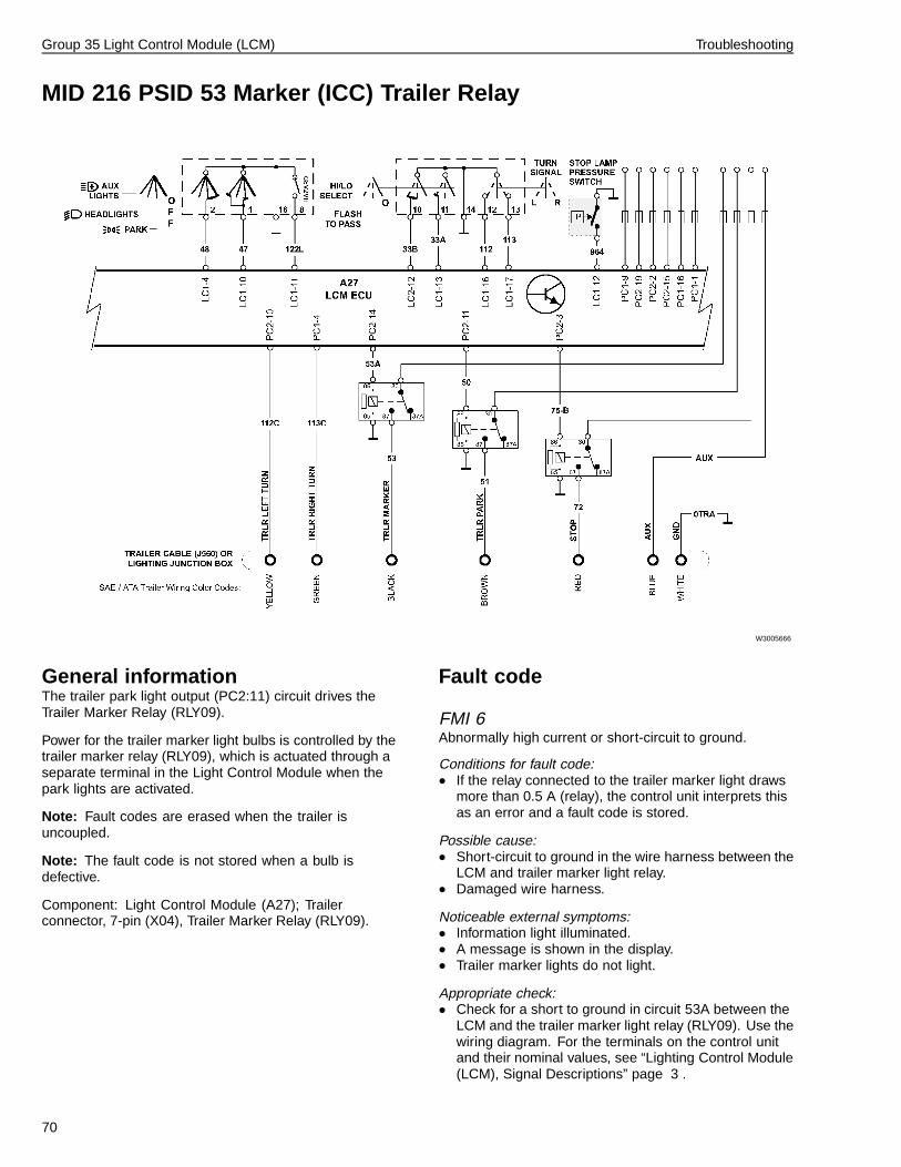
Group 35 Light Control Module (LCM) Troubleshooting
MID 216 PSID 53 Marker (ICC) Trailer Relay
W3005666
General informationThe trailer park light output (PC2:11) circuit drives theTrailer Marker Relay (RLY09).
Power for the trailer marker light bulbs is controlled by thetrailer marker relay (RLY09), which is actuated through aseparate terminal in the Light Control Module when thepark lights are activated.
Note: Fault codes are erased when the trailer isuncoupled.
Note: The fault code is not stored when a bulb isdefective.
Component: Light Control Module (A27); Trailerconnector, 7-pin (X04), Trailer Marker Relay (RLY09).
Fault code
FMI 6Abnormally high current or short-circuit to ground.
Conditions for fault code:• If the relay connected to the trailer marker light draws
more than 0.5 A (relay), the control unit interprets thisas an error and a fault code is stored.
Possible cause:• Short-circuit to ground in the wire harness between the
LCM and trailer marker light relay.• Damaged wire harness.
Noticeable external symptoms:• Information light illuminated.• A message is shown in the display.• Trailer marker lights do not light.
Appropriate check:• Check for a short to ground in circuit 53A between the
LCM and the trailer marker light relay (RLY09). Use thewiring diagram. For the terminals on the control unitand their nominal values, see “Lighting Control Module(LCM), Signal Descriptions” page 3 .
70

Group 35 Light Control Module (LCM) Troubleshooting
MID 216 PSID 54 Marker Interrupt
W3005294
W3005296
General informationComponent: Switch steering wheel push buttons (S34),Control unit SWM (steering functions) (A30), Contact reelair bag (X08), Control unit (LCM) exterior lighting (A27).
Fault code
FMI 12Defective unit or component.
Condition for fault code:
• If “Marker interrupt” button is depressed for longer thanone minute, the control unit will interpret this as anerror and the fault code will be set.
Possible cause:
• Button depressed for longer than one minute.
• Faulty button set.
Reaction from control unit:
• Fault code set.
• Information lamp requested.
• Fault message is sent to the instrument cluster.
• “Marker interrupt” is switched off after 3 seconds.
Noticeable external symptom:
• Information lamp illuminated.
• “Marker interrupt” does not function.
Appropriate inspection:
• Perform the appropriate steering wheel switch test,see service information “Steering Wheel Module FaultCodes”.
71

Group 35 Light Control Module (LCM) Troubleshooting
MID 216 PSID 55 Headlamp Interrupt
W3005294
W3005296
General informationComponent: Switch steering wheel push buttons (S34),Control unit SWM (steering functions) (A30), Contact reelair bag (X08), Control unit (LCM) exterior lighting (A27).
Fault code
FMI 12Defective unit or component.
Condition for fault code:
• If “Headlamp interrupt” button is depressed for longerthan one minute, the control unit will interpret this asan error and the fault code will be set.
Possible cause:
• Button depressed for longer than one minute.
• Faulty button set.
Reaction from control unit:
• Fault code set.
• Information lamp requested.
• Fault message is sent to the instrument cluster.
• “Headlamp interrupt” is switched off after 3 seconds.
Noticeable external symptom:
• Information lamp illuminated.
• “Headlamp interrupt” does not function.
Appropriate inspection:
• Perform the appropriate steering wheel switch test,see service information “Steering Wheel Module FaultCodes”.
72

Group 35 Light Control Module (LCM) Troubleshooting
MID 216 PSID 57 Back of Cab Lights
W3005725
General informationPower for the back of cab lamps are supplied by aseparate terminal in the Light Control Module.
Component: Back of Cab Lamps (E05); Switch, Back ofCab Lamps (S76); Light Control Module (A27).
Fault code
FMI 5Abnormally low current or open-circuit.
Conditions for fault code:• If the bulbs connected to the back of cab lamps draw
less than 2 W (0.1 A), the LCM interprets this as anerror and a fault code is stored.
Possible cause:• Back of cab lamps are defective.• Open-circuit in the wiring harness between the LCM
and the back of cab lamps.• Open-circuit in the wiring harness between the back
of cab lamps and ground.
Noticeable external symptoms:• Information light illuminated.• Warning light “Bulb failure warning sensor” illuminated.• A message is shown in the display.• Back of cab lamps do not light.
Appropriate check:• Replace back of cab light bulbs.• Check for an open in circuit 139 between the back of
cab lamps and the LCM. Use the wiring diagram. Forthe terminals on the LCM and their nominal values, see“Lighting Control Module (LCM), Signal Descriptions”page 3 .
• Check for an open ground circuit for the back of cablamps. Use the wiring diagram.
FMI 6Abnormally high current or short-circuit to ground.
Conditions for fault code:• If the bulbs connected to the back of cab lamps draw
more than 117 W (9.78 A), the LCM interprets this asan error and a fault code is stored.
Note: If the voltage to the LCM is more than 16V a faultcode is not stored.
Possible cause:• Short-circuit to ground in the wiring harness between
the LCM and the back of cab lamps.• Too many/powerful bulbs directly connected to the
LCM.
Noticeable external symptoms:• Information light illuminated.• A message is shown in the display.• Back of cab lamps do not light.
Appropriate check:• Check for a short to ground in circuit 139 between the
back of cab lamps and LCM. Use the wiring diagram.For the terminals on the LCM and their nominalvalues, see “Lighting Control Module (LCM), SignalDescriptions” page 3 .
73

Group 35 Light Control Module (LCM) Troubleshooting
MID 216 PSID 200 J1939 Data Link Interruption, Engine ECUGeneral informationThe control units share important information throughthe J1939 control data link. If a control unit is missing amessage from another control unit this fault code is usedto indicate the control unit that is expected to transmit themessage on the J1939 control data link failed to transmit.
For further information regarding the J1939 control datalink, see service information group 3, “Data Links, FaultTracing”
Note: The fault codes are only stored if the messagedisappears during the operating cycle. The messagemust have been sent earlier during that operating cycle.The control unit automatically configures itself to thecontrol units available in the vehicle.
Fault code
FMI 9Abnormal update rate.
Conditions for fault code:• If the control unit does not receive the message within
a specific period from the engine control unit throughthe J1939 control data link, the LCM interprets this asan error and a fault code is stored.
Possible cause:• Open-circuit in the J1939 control data link between the
LCM and the engine control unit.
Noticeable external symptoms:• Warning light illuminated.
Appropriate check:• Fault-trace the J1939 control data link, see service
information “Data Links, Fault Tracing”.
MID 216 PSID 201 J1939 Data Link Interruption, Vehicle ECUGeneral informationThe control units share important information throughthe J1939 control data link. If a control unit is missing amessage from another control unit this fault code is usedto indicate the control unit that is expected to transmit themessage through the J1939 control data link.
For further information regarding the J1939 control datalink, see service information group 0, “Vehicle Electronics”
Note: The fault codes are only stored if the messagedisappears during the operating cycle. The messagemust have been sent earlier during that operating cycle.The control unit automatically configures itself to thecontrol units available in the vehicle.
Fault code
FMI 9Abnormal update rate.
Conditions for fault code:• If the control unit does not receive the message within
a specific period from the vehicle control unit throughthe J1939 control data link, the LCM interprets this asan error and a fault code is stored.
Possible cause:• Open-circuit in the J1939 control data link between the
LCM and the vehicle control unit.
Noticeable external symptoms:• Warning light illuminated.• Automatic low light function does not function.
Appropriate check:• Fault-trace the J1939 control data link, see service
information “Data Links, Fault Tracing”.
74

Operation Numbers
3500-21-02-01 MID 216 PSID 19 Relay, Intermittent Wiper, Check ................................................................................. 33
3500-21-03-02 MID 216 PSID 29/30/42 Lighting Control Switch, Check ......................................................................... 42


Volvo Trucks North America, Inc.P.O. Box 26115, Greensboro, NC 27402-6115
Volvo Trucks Canada, Ltd.5600A Cancross Court, Mississauga, Ontario L5R 3E9
http://www.volvotrucks.volvo.com
PV776-20 033682 (08.2005) 08.2005 © Volvo Trucks North America, Inc., 2005


