56
Technical Information Electrohydraulic Actuator PVE Series 7 powersolutions.danfoss.com

Technical Information
Electrohydraulic ActuatorPVE Series 7
powersolutions.danfoss.com
Revision history Table of revisions
Date Changed Rev
January 2016 Minor updates 0102
November 2016 First edition 0101
Technical InformationPVE Series 7
2 | © Danfoss | January 2016 BC00000378en-US0102

PVE Electrical ActuatorPVE Electrical Actuator....................................................................................................................................................................5
PVE Variant OverviewPVE Variant Overview......................................................................................................................................................................7
PVEOPVEO Schematics and Dimensions............................................................................................................................................ 9PVEO Technical Data.....................................................................................................................................................................10PVEO Reaction Times....................................................................................................................................................................11PVEO Variants for PVG.................................................................................................................................................................. 11
PVEO-HPPVEO-HP Schematics and Dimensions...................................................................................................................................13PVEO-HP Technical Data..............................................................................................................................................................14PVEO-HP Reaction Times.............................................................................................................................................................15PVEO-HP Variants for PVG...........................................................................................................................................................15
PVEMPVEM Schematics and Dimensions......................................................................................................................................... 16PVEM Technical Data.................................................................................................................................................................... 17PVEM Reaction Times................................................................................................................................................................... 18PVEM Hysteresis and Ripple.......................................................................................................................................................19PVEM Variants for PVG................................................................................................................................................................. 19
PVEAPVEA Schematics and Dimensions.......................................................................................................................................... 20PVEA Technical Data..................................................................................................................................................................... 21PVEA Reaction Times.................................................................................................................................................................... 22PVEA Hysteresis and Ripple........................................................................................................................................................23PVEA Variants for PVG.................................................................................................................................................................. 23
PVEHPVEH Schematics and Dimensions.......................................................................................................................................... 24PVEH Technical Data.....................................................................................................................................................................25PVEH Reaction Times.................................................................................................................................................................... 26PVEH Hysteresis and Ripple........................................................................................................................................................27PVEH Variants for PVG.................................................................................................................................................................. 27
PVESPVES Schematics and Dimensions...........................................................................................................................................29PVES Technical Data......................................................................................................................................................................30PVES Reaction Times.....................................................................................................................................................................31PVES Hysteresis and Ripple........................................................................................................................................................ 32PVES Variants for PVG...................................................................................................................................................................32
Connector OverviewConnector Overview..................................................................................................................................................................... 33
Fault Monitoring and Fault ReactionGeneric Fault Reaction................................................................................................................................................................. 35Fault Reaction Overview..............................................................................................................................................................35
Functionality OverviewStandard and Fixed US 0-10 Vdc.............................................................................................................................................. 36
PWM Voltage Control..............................................................................................................................................................37Ramp (-R)...........................................................................................................................................................................................38Quick Reaction (-Q)........................................................................................................................................................................39Float B-Port (-FLB).......................................................................................................................................................................... 40Float A-Port (-FLA)..........................................................................................................................................................................41Power Save....................................................................................................................................................................................... 41
Special FeaturesDirection Indication (-DI).............................................................................................................................................................42
Technical InformationPVE Series 7
Contents
© Danfoss | January 2016 BC00000378en-US0102 | 3
Dedicated Float Pin (UF)..............................................................................................................................................................44Spool Position (-SP)....................................................................................................................................................................... 45Neutral Power-OFF (-NP)............................................................................................................................................................. 47Disable Mode...................................................................................................................................................................................48
Performance OverviewReaction Times................................................................................................................................................................................49Hysteresis and Ripple................................................................................................................................................................... 50Current Consumption.................................................................................................................................................................. 50Oil Consumption............................................................................................................................................................................ 51
Dimension OverviewDimension Overview.................................................................................................................................................................... 52
Technical InformationPVE Series 7
Contents
4 | © Danfoss | January 2016 BC00000378en-US0102

PVE Electrical Actuator
The analog PVE Series 7 is an electro-hydraulic actuator used to control a single work section of a PVGproportional valve group. The PVE Series 7 actuator program includes variants with differentperformance levels and features for PVG 32/100/120/128/256.
The actuator positions the main spool in a PVG work section in order to control either the flow or thepressure of the oil distributed to/from the work function. The control signal to the actuator is an analogvoltage signal, enabling the user to operate the work function remotely by means of a joystick, acontroller or the similar.
The analog PVE Series 7 actuator program features five different main hydraulic principle variants (PVEO/PVEM/PVEA/PVEH/PVES). The different hydraulic principles combined with the different solenoid valveregulation principles determine whether the actuator controls the spool proportionally according to ademand signal or ON/OFF according to a voltage signal.
The electro-hydraulic solenoid valve bridge of the actuator is available in different designs utilizingdifferent regulation principles, depending on performance variant. The actuator positions the main spoolby distributing pilot oil pressure to either side of it, pressurizing one side by pilot pressure while relievingthe opposite side to tank and vice versa, as illustrated below. All proportional actuators feature a closed-loop spool control and continuous fault monitoring.
PVG 32 with PVEO/PVEM (PVEO without LVDT)
Technical InformationPVE Series 7
PVE Electrical Actuator
© Danfoss | January 2016 BC00000378en-US0102 | 5
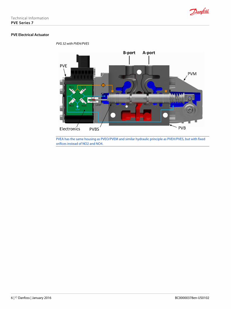
PVG 32 with PVEH/PVES
PVEA has the same housing as PVEO/PVEM and similar hydraulic principle as PVEH/PVES, but with fixedorifices instead of NO2 and NO4.
Technical InformationPVE Series 7
PVE Electrical Actuator
6 | © Danfoss | January 2016 BC00000378en-US0102

PVE Variant Overview
Symbol Description
P109195
PVEOON/OFF voltage control for non-proportional functions.• Neutral position or maximum spool stroke according to control signal• Variants available with 12 Vdc or 24 Vdc supply voltage• Variants available with DEUTSCH, AMP or DIN/Hirschmann connectors• To be used with standard PVE pilot oil pressure of 13.5 bar• LED only indicating Power ON or Power OFF• Variants available with Ramp (-R) or Direction Indication output (-DI) functionality
P109195
PVEO-HPON/OFF voltage control for non-proportional functions.• Neutral position or max. spool stroke acc. to control signal• Variants available for 12 Vdc or 24 Vdc power supply• Variants available with DEUTSCH, AMP or DIN/Hirschmann connectors• To be used with PVH/PVHC pilot oil pressure of 25 bar• LED only indicating Power ON or Power OFF
P109196
PVEMProportional spool control for functions with medium performance demands.• All variants with 9-32 Vdc multi-voltage power supply• Variants only available with DIN/Hirschmann connectors• To be used with standard PVE pilot oil pressure of 13.5 bar• All variants with LED indicating error state and passive fault monitoring• Variants available with Float (-F), Quick Ramp (-R) or Quick Reaction functionality
P109197
PVEAProportional spool control for functions with high performance demands.• All variants with 9-32 Vdc multi-voltage power supply• Variants available with DEUTSCH, AMP or DIN/Hirschmann connectors• To be used with standard PVE pilot oil pressure of 13.5 bar• All variants with LED indicating error state and active or passive fault monitoring• Variants available with Direction Indication output (-DI) or Neutral Power-Off (-NP)
functionality
Technical InformationPVE Series 7
PVE Variant Overview
© Danfoss | January 2016 BC00000378en-US0102 | 7
Symbol Description
P109198
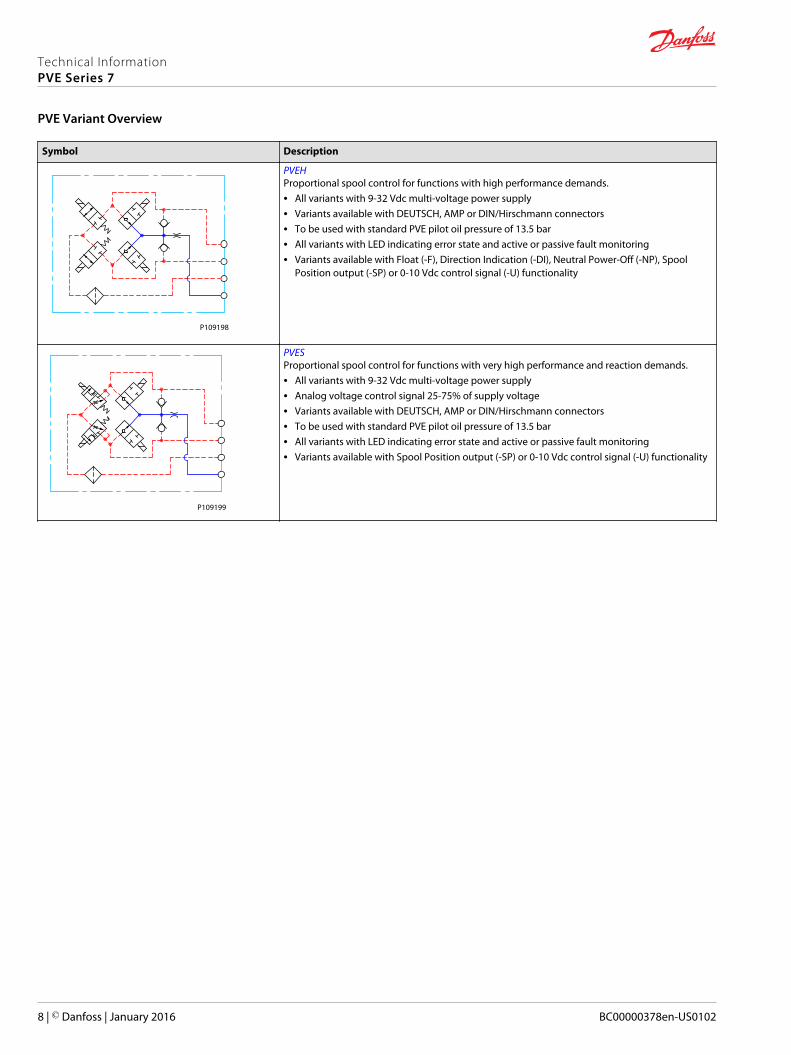
PVEHProportional spool control for functions with high performance demands.• All variants with 9-32 Vdc multi-voltage power supply• Variants available with DEUTSCH, AMP or DIN/Hirschmann connectors• To be used with standard PVE pilot oil pressure of 13.5 bar• All variants with LED indicating error state and active or passive fault monitoring• Variants available with Float (-F), Direction Indication (-DI), Neutral Power-Off (-NP), Spool
Position output (-SP) or 0-10 Vdc control signal (-U) functionality
P109199
PVESProportional spool control for functions with very high performance and reaction demands.• All variants with 9-32 Vdc multi-voltage power supply• Analog voltage control signal 25-75% of supply voltage• Variants available with DEUTSCH, AMP or DIN/Hirschmann connectors• To be used with standard PVE pilot oil pressure of 13.5 bar• All variants with LED indicating error state and active or passive fault monitoring• Variants available with Spool Position output (-SP) or 0-10 Vdc control signal (-U) functionality
Technical InformationPVE Series 7
PVE Variant Overview
8 | © Danfoss | January 2016 BC00000378en-US0102

The PVEO actuator is a non-proportional ON/OFF control actuator with open-loop spool control primarilyused to control simple ON/OFF work functions where a proportional control of speed or oil flow is not arequirement. The PVEO is available in two different performance variants, the standard PVEO and thePVEO-R with ramp.
The standard PVEO functionality includes the simplest electric circuit of the PVE Series 7 actuatorprogram, using a fixed 12 Vdc or 24 Vdc supply voltage or signal voltage and a simple LED circuit tocontrol the LED light indicating Power ON/OFF.
The PVEO-DI variant includes an LVDT spool position monitor and a more advanced electric circuit withan embedded micro-controller and separate power supply to handle the Direction Indicationfunctionality.
An energization of solenoid valve SV1 and a simultaneous de-energization of SV2 will cause the mainspool to move to the right direction and vice versa. If both SV1 and SV2 are energized or de-energizedsimultaneously, the main spool stays locked in its neutral position.
Functionality
PVEO
21 0
Pp
LVDT
LED Circuit /Microcontroller
PowerSupply
PVEO-DI
AB
DI_BDI_A
LED
Udc
Ramp Ramp
SV1 SV2
P109126
PVEO Schematics and Dimensions
Schematics
PVEO PVEO-R
P109195 P109200
Technical InformationPVE Series 7
PVEO
© Danfoss | January 2016 BC00000378en-US0102 | 9
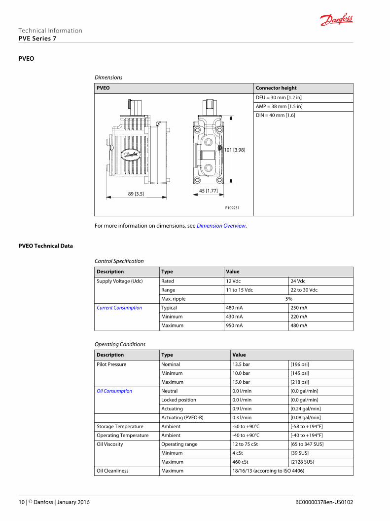
Dimensions
PVEO Connector height
101 [3.98]
45 [1.77]89 [3.5]
P109231
DEU = 30 mm [1.2 in]
AMP = 38 mm [1.5 in]
DIN = 40 mm [1.6]
For more information on dimensions, see Dimension Overview.
PVEO Technical Data
Control Specification
Description Type Value
Supply Voltage (Udc) Rated 12 Vdc 24 Vdc
Range 11 to 15 Vdc 22 to 30 Vdc
Max. ripple 5%
Current Consumption Typical 480 mA 250 mA
Minimum 430 mA 220 mA
Maximum 950 mA 480 mA
Operating Conditions
Description Type Value
Pilot Pressure Nominal 13.5 bar [196 psi]
Minimum 10.0 bar [145 psi]
Maximum 15.0 bar [218 psi]
Oil Consumption Neutral 0.0 l/min [0.0 gal/min]
Locked position 0.0 l/min [0.0 gal/min]
Actuating 0.9 l/min [0.24 gal/min]
Actuating (PVEO-R) 0.3 l/min [0.08 gal/min]
Storage Temperature Ambient -50 to +90°C [-58 to +194°F]
Operating Temperature Ambient -40 to +90°C [-40 to +194°F]
Oil Viscosity Operating range 12 to 75 cSt [65 to 347 SUS]
Minimum 4 cSt [39 SUS]
Maximum 460 cSt [2128 SUS]
Oil Cleanliness Maximum 18/16/13 (according to ISO 4406)
Technical InformationPVE Series 7
PVEO
10 | © Danfoss | January 2016 BC00000378en-US0102

LED Characteristic
Color LED Characteristic Description
Green Power ON
PVEO Reaction Times
100
0Time
T0 T1
T2
P109128
Spool positionDemand Signal (Us)Supply Voltage (U dc)
Spool pos. [%]
Reaction PVEO/PVEO-DI PVEO-R
T0 – Boot-up [ms] 0 0
T1 – Neutral to max. spool stroke @ Power ON [ms] 110 300
T2 – Max. spool stroke to neutral @ Power OFF [ms] 110 110
T1 – Neutral to max. spool stroke @ Constant Udc [ms] 110 300
T2 – Max. spool stroke to neutral @ Constant Udc [ms] 110 110
The stated values are preliminary values and can be subject to change once an increased statistical basisis achieved.
For more information on reaction times, see Reaction Times.
PVEO Variants for PVG
PVG 32/100 Variants
Part number Type Connector IP Udc Functionality
11166843 PVEO 1x4 DEU 67 12 Vdc Standard
11166838 PVEO 1x4 DEU 67 24 Vdc Standard
11166866 PVEO 1x4 AMP 66 12 Vdc Standard
11166837 PVEO 1x4 AMP 66 24 Vdc Standard
11166836 PVEO 1x4 DIN 65 12 Vdc Standard
11166743 PVEO 1x4 DIN 65 24 Vdc Standard
11166753 PVEO-R 1x4 DEU 67 12 Vdc Ramp
11166754 PVEO-R 1x4 DEU 67 24 Vdc Ramp
11166867 PVEO-R 1x4 AMP 66 12 Vdc Ramp
11166776 PVEO-R 1x4 AMP 66 24 Vdc Ramp
11166831 PVEO-R 1x4 DIN 65 12 Vdc Ramp
11166908 PVEO-R 1x4 DIN 65 24 Vdc Ramp
Technical InformationPVE Series 7
PVEO
© Danfoss | January 2016 BC00000378en-US0102 | 11
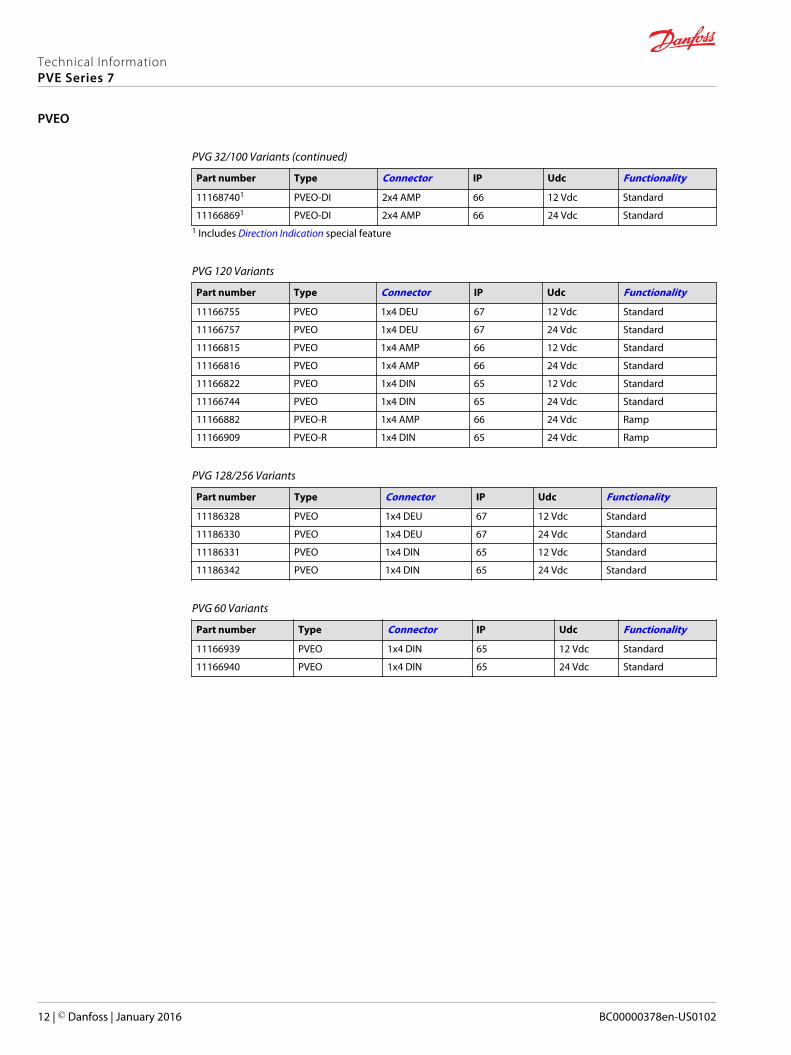
PVG 32/100 Variants (continued)
Part number Type Connector IP Udc Functionality
111687401 PVEO-DI 2x4 AMP 66 12 Vdc Standard
111668691 PVEO-DI 2x4 AMP 66 24 Vdc Standard1 Includes Direction Indication special feature
PVG 120 Variants
Part number Type Connector IP Udc Functionality
11166755 PVEO 1x4 DEU 67 12 Vdc Standard
11166757 PVEO 1x4 DEU 67 24 Vdc Standard
11166815 PVEO 1x4 AMP 66 12 Vdc Standard
11166816 PVEO 1x4 AMP 66 24 Vdc Standard
11166822 PVEO 1x4 DIN 65 12 Vdc Standard
11166744 PVEO 1x4 DIN 65 24 Vdc Standard
11166882 PVEO-R 1x4 AMP 66 24 Vdc Ramp
11166909 PVEO-R 1x4 DIN 65 24 Vdc Ramp
PVG 128/256 Variants
Part number Type Connector IP Udc Functionality
11186328 PVEO 1x4 DEU 67 12 Vdc Standard
11186330 PVEO 1x4 DEU 67 24 Vdc Standard
11186331 PVEO 1x4 DIN 65 12 Vdc Standard
11186342 PVEO 1x4 DIN 65 24 Vdc Standard
PVG 60 Variants
Part number Type Connector IP Udc Functionality
11166939 PVEO 1x4 DIN 65 12 Vdc Standard
11166940 PVEO 1x4 DIN 65 24 Vdc Standard
Technical InformationPVE Series 7
PVEO
12 | © Danfoss | January 2016 BC00000378en-US0102

The PVEO-HP actuator is a high pressure non-proportional ON/OFF control actuator with open-loop spoolcontrol primarily used to control simple ON/OFF work functions where a proportional control of speed oroil flow is not a requirement.
The standard PVEO-HP functionality includes the simplest electric circuit of the PVE Series 7 actuatorprogram, using a fixed 12 Vdc or 24V dc supply voltage or signal voltage and a simple LED circuit tocontrol the LED light indicating Power ON/OFF.
An energization of solenoid valve SV1 and a simultaneous de-energization of SV2 will cause the mainspool to move to the right direction and vice versa. If both SV1 and SV2 are energized or de-energizedsimultaneously, the main spool stays locked in its neutral position.
Functionality
PVEO-HP
21 0
Pp
LED
AB
LED Circuit
SV1 SV2
P109130
PVEO-HP Schematics and Dimensions
Schematics
PVEO-HP
P109195
Technical InformationPVE Series 7
PVEO-HP
© Danfoss | January 2016 BC00000378en-US0102 | 13

Dimensions
PVEO-HP Connector height
101 [3.98]
45 [1.77]89 [3.5]
P109231
DEU = 30 mm [1.2 in]
AMP = 38 mm [1.5 in]
DIN = 40 mm [1.6 in]
For more information on dimensions, please see Dimension Overview.
PVEO-HP Technical Data
Control Specification
Description Type Value
Supply Voltage (Udc) Rated 12 Vdc 24 Vdc
Range 11 to 15 Vdc 22 to 30 Vdc
Max. ripple 5%
Current Consumption Typical 750 mA 380 mA
Minimum 660 mA 340 mA
Maximum 1460 mA 740 mA
Operating Conditions
Description Type Value
Pilot Pressure Nominal 25.0 bar [363 psi]
Minimum 21.0 bar [305 psi]
Maximum 25.0 bar [363 psi]
Oil Consumption Neutral 0.0 l/min [0.0 gal/min]
Locked position 0.0 l/min [0.0 gal/min]
Actuating 0.9 l/min [0.24 gal/min]
Storage Temperature Ambient -50 to +90°C [-58 to +194°F]
Operating Temperature Ambient -40 to +90°C [-40 to +194°F]
Oil Viscosity Operating range 12 to 75 cSt [65 to 347 SUS]
Minimum 4 cSt [39 SUS]
Maximum 460 cSt [2128 SUS]
Oil Cleanliness Maximum 18/16/13 (according to ISO 4406)
Technical InformationPVE Series 7
PVEO-HP
14 | © Danfoss | January 2016 BC00000378en-US0102
LED Characteristic
Color LED Characteristic Description
Green Power ON
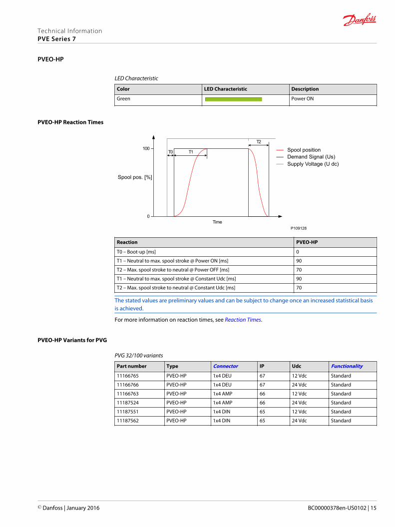
PVEO-HP Reaction Times
100
0Time
T0 T1
T2
P109128
Spool positionDemand Signal (Us)Supply Voltage (U dc)
Spool pos. [%]
Reaction PVEO-HP
T0 – Boot-up [ms] 0
T1 – Neutral to max. spool stroke @ Power ON [ms] 90
T2 – Max. spool stroke to neutral @ Power OFF [ms] 70
T1 – Neutral to max. spool stroke @ Constant Udc [ms] 90
T2 – Max. spool stroke to neutral @ Constant Udc [ms] 70
The stated values are preliminary values and can be subject to change once an increased statistical basisis achieved.
For more information on reaction times, see Reaction Times.
PVEO-HP Variants for PVG
PVG 32/100 variants
Part number Type Connector IP Udc Functionality
11166765 PVEO-HP 1x4 DEU 67 12 Vdc Standard
11166766 PVEO-HP 1x4 DEU 67 24 Vdc Standard
11166763 PVEO-HP 1x4 AMP 66 12 Vdc Standard
11187524 PVEO-HP 1x4 AMP 66 24 Vdc Standard
11187551 PVEO-HP 1x4 DIN 65 12 Vdc Standard
11187562 PVEO-HP 1x4 DIN 65 24 Vdc Standard
Technical InformationPVE Series 7
PVEO-HP
© Danfoss | January 2016 BC00000378en-US0102 | 15

The PVEM actuator is a proportional control actuator with closed-loop spool control primarily used tocontrol work functions with medium performance requirements. The PVEM is available in three differentperformance variants, the standard PVEM, the PVEM-R with ramp and the PVEM-Q with quick reaction.
The PVEM functionality includes an electric circuit with a closed-loop logic. An embedded micro-controller processes the signal voltage and the LVDT feedback signal and regulates the solenoid valvesaccordingly. Features such as passive fault monitoring, LED indicating fault state, error output pin andPower Save are all default PVEM features.
An energization of solenoid valve SV1 and a simultaneous stepwise modulation of SV2 causes the mainspool to move to the right direction and vice versa. When the main spool is stroked to the far right, asimultaneous energization of both SV1 and SV2 locks the main spool in its stroked position. When bothSV1 and SV2 are de-energized the main spool moves back to its neutral position by means of the mainspool neutral spring and the hydraulic principle.
Functionality
PVEM
21 0
Pp
LVDT
SV2SV1
Micro-controller
PowerSupply
UDC
US
ErrorLED
P109132
PVEM Schematics and Dimensions
Schematics
PVEM/PVEM-FLB/PVEM-R PVEM-Q
P109196 P109201
Technical InformationPVE Series 7
PVEM
16 | © Danfoss | January 2016 BC00000378en-US0102
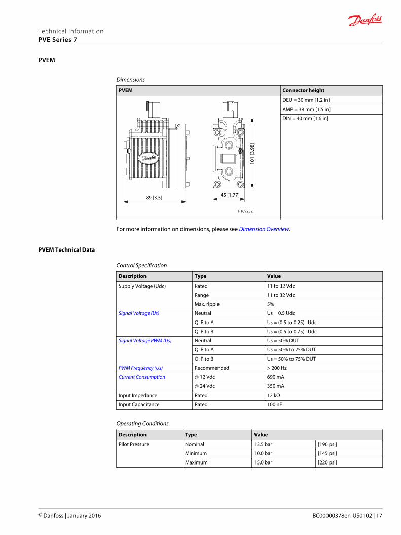
Dimensions
PVEM Connector height
101
[3.9
8]
45 [1.77]89 [3.5]
P109232
DEU = 30 mm [1.2 in]
AMP = 38 mm [1.5 in]
DIN = 40 mm [1.6 in]
For more information on dimensions, please see Dimension Overview.
PVEM Technical Data
Control Specification
Description Type Value
Supply Voltage (Udc) Rated 11 to 32 Vdc
Range 11 to 32 Vdc
Max. ripple 5%
Signal Voltage (Us) Neutral Us = 0.5 Udc
Q: P to A Us = (0.5 to 0.25) · Udc
Q: P to B Us = (0.5 to 0.75) · Udc
Signal Voltage PWM (Us) Neutral Us = 50% DUT
Q: P to A Us = 50% to 25% DUT
Q: P to B Us = 50% to 75% DUT
PWM Frequency (Us) Recommended > 200 Hz
Current Consumption @ 12 Vdc 690 mA
@ 24 Vdc 350 mA
Input Impedance Rated 12 kΩ
Input Capacitance Rated 100 nF
Operating Conditions
Description Type Value
Pilot Pressure Nominal 13.5 bar [196 psi]
Minimum 10.0 bar [145 psi]
Maximum 15.0 bar [220 psi]
Technical InformationPVE Series 7
PVEM
© Danfoss | January 2016 BC00000378en-US0102 | 17
Operating Conditions (continued)
Description Type Value
Oil Consumption Neutral 0.0 l/min [0.0 gal/min]
Locked Position 0.0 l/min [0.0 gal/min]
Actuating 0.5 l/min [0.13 gal/min]
Actuating (PVEM-R) 0.3 l/min [0.07 gal/min]
Actuating (PVEM-Q) 1.0 l/min [0.26 gal/min]
Storage Temperature Ambient -50 to +90°C [-58 to +194°F]
Operating Temperature Ambient -40 to +90°C [-40 to +194°F]
Oil Viscosity Operating range 12 to 75 cSt [65 to 347 SUS]
Minimum 4 cSt [39 SUS]
Maximum 460 cSt [2128 SUS]
Oil Cleanliness Maximum 18/16/13 (according to ISO 4406)
LED Characteristic
Color LED Characteristics Description
Green Operating
Green @ 1.5 Hz Neutral - Power Save
Red Internal fault
Red @ 1.5 Hz External or float fault
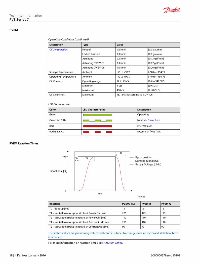
PVEM Reaction Times
100
0Time
T0 T1
T2
P109128
Spool positionDemand Signal (Us)Supply Voltage (U dc)
Spool pos. [%]
Reaction PVEM/-FLB PVEM-R PVEM-Q
T0 – Boot-up [ms] 15 15 15
T1 – Neutral to max. spool stroke @ Power ON [ms] 225 325 125
T2 – Max. spool stroke to neutral @ Power OFF [ms] 110 110 110
T1 – Neutral to max. spool stroke @ Constant Udc [ms] 210 310 110
T2 – Max. spool stroke to neutral @ Constant Udc [ms] 90 90 90
The stated values are preliminary values and can be subject to change once an increased statistical basisis achieved.
For more information on reaction times, see Reaction Times.
Technical InformationPVE Series 7
PVEM
18 | © Danfoss | January 2016 BC00000378en-US0102

PVEM Hysteresis and Ripple
US [%]
100
0
Spool Position [%]
100(0.75 ∙ U dc)
BP
h
50(0.50 ∙ U dc)
vFixed pos.
Spool Position
P109146
Description Type PVEM
Hysteresis (h) Rated [%] 15
Steady state ripple @ fixed US (v) Rated [mm] 0.0
The stated values are preliminary values and can be subject to change once an increased statistical basisis achieved.
For more information on hysteresis and ripple, see Hysteresis and Ripple.
PVEM Variants for PVG
PVG 32/100 Variants
Part number Type Connector IP Fault Monitoring Functionality
11166829 PVEM 1x4 DIN 65 Passive Standard
11166852 PVEM-FLB 1x4 DIN 65 Passive Float B-port
11166845 PVEM-R 1x4 DIN 65 Passive Ramp
11166853 PVEM-Q 1x4 DIN 65 Passive Quick Reaction
Technical InformationPVE Series 7
PVEM
© Danfoss | January 2016 BC00000378en-US0102 | 19
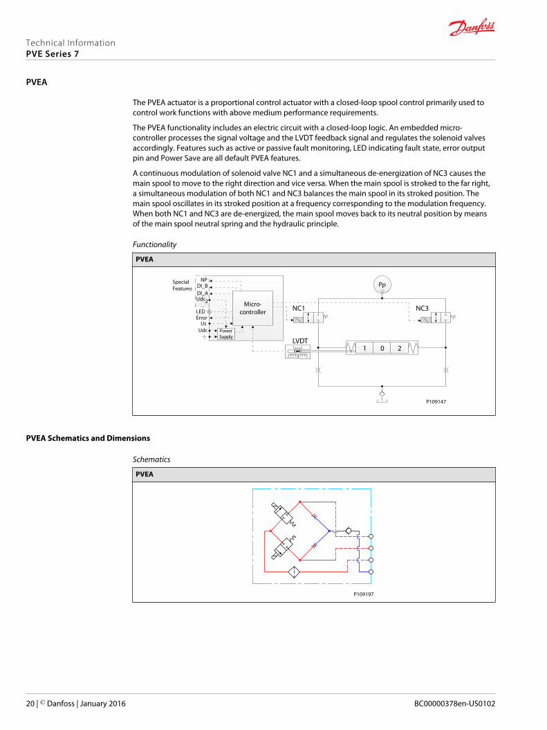
The PVEA actuator is a proportional control actuator with a closed-loop spool control primarily used tocontrol work functions with above medium performance requirements.
The PVEA functionality includes an electric circuit with a closed-loop logic. An embedded micro-controller processes the signal voltage and the LVDT feedback signal and regulates the solenoid valvesaccordingly. Features such as active or passive fault monitoring, LED indicating fault state, error outputpin and Power Save are all default PVEA features.
A continuous modulation of solenoid valve NC1 and a simultaneous de-energization of NC3 causes themain spool to move to the right direction and vice versa. When the main spool is stroked to the far right,a simultaneous modulation of both NC1 and NC3 balances the main spool in its stroked position. Themain spool oscillates in its stroked position at a frequency corresponding to the modulation frequency.When both NC1 and NC3 are de-energized, the main spool moves back to its neutral position by meansof the main spool neutral spring and the hydraulic principle.
Functionality
PVEA
21 0
Pp
Micro-controller
PowerSupply
NPDI_BDI_AUdc
LEDError
UsUdc
2
SpecialFeatures
NC1 NC3
LVDT
P109147
PVEA Schematics and Dimensions
Schematics
PVEA
P109197
Technical InformationPVE Series 7
PVEA
20 | © Danfoss | January 2016 BC00000378en-US0102
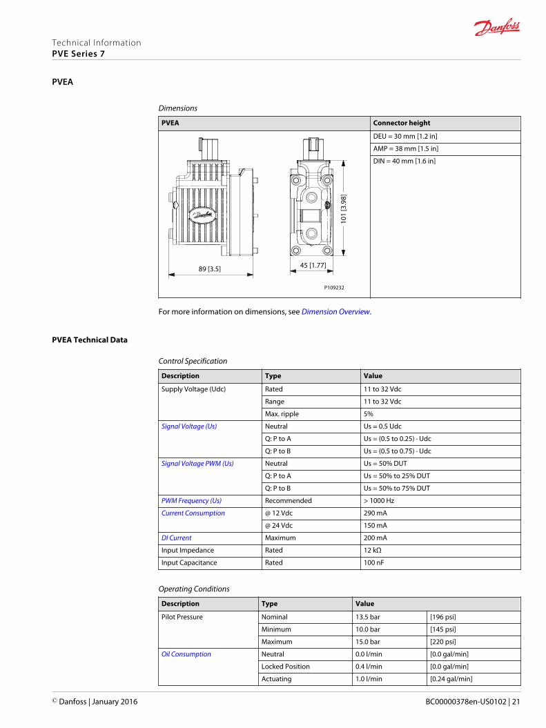
Dimensions
PVEA Connector height
101
[3.9
8]
45 [1.77]89 [3.5]
P109232
DEU = 30 mm [1.2 in]
AMP = 38 mm [1.5 in]
DIN = 40 mm [1.6 in]
For more information on dimensions, see Dimension Overview.
PVEA Technical Data
Control Specification
Description Type Value
Supply Voltage (Udc) Rated 11 to 32 Vdc
Range 11 to 32 Vdc
Max. ripple 5%
Signal Voltage (Us) Neutral Us = 0.5 Udc
Q: P to A Us = (0.5 to 0.25) ∙ Udc
Q: P to B Us = (0.5 to 0.75) ∙ Udc
Signal Voltage PWM (Us) Neutral Us = 50% DUT
Q: P to A Us = 50% to 25% DUT
Q: P to B Us = 50% to 75% DUT
PWM Frequency (Us) Recommended > 1000 Hz
Current Consumption @ 12 Vdc 290 mA
@ 24 Vdc 150 mA
DI Current Maximum 200 mA
Input Impedance Rated 12 kΩ
Input Capacitance Rated 100 nF
Operating Conditions
Description Type Value
Pilot Pressure Nominal 13.5 bar [196 psi]
Minimum 10.0 bar [145 psi]
Maximum 15.0 bar [220 psi]
Oil Consumption Neutral 0.0 l/min [0.0 gal/min]
Locked Position 0.4 l/min [0.0 gal/min]
Actuating 1.0 l/min [0.24 gal/min]
Technical InformationPVE Series 7
PVEA
© Danfoss | January 2016 BC00000378en-US0102 | 21
Operating Conditions (continued)
Description Type Value
Storage Temperature Ambient -50 to +90°C [-58 to +194°F]
Operating Temperature Ambient -40 to +90°C [-40 to +194°F]
Oil Viscosity Operating range 12 to 75 cSt [65 to 347 SUS]
Minimum 4 cSt [39 SUS]
Maximum 460 cSt [2128 SUS]
Oil Cleanliness Maximum 18/16/13 (according to ISO 4406)
LED Characteristic
Color LED Characteristic Description
Green Actuating
Green @ 1.5 Hz Neutral - Power Save
Red Internal fault
Red @ 1.5 Hz External or Float fault
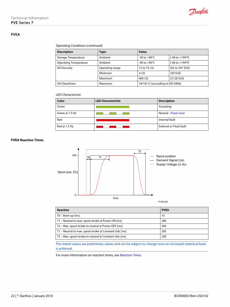
PVEA Reaction Times
100
0Time
T0 T1
T2
P109128
Spool positionDemand Signal (Us)Supply Voltage (U dc)
Spool pos. [%]
Reaction PVEA
T0 – Boot-up [ms] 15
T1 – Neutral to max. spool stroke @ Power ON [ms] 280
T2 – Max. spool stroke to neutral @ Power OFF [ms] 200
T1 – Neutral to max. spool stroke @ Constant Udc [ms] 265
T2 – Max. spool stroke to neutral @ Constant Udc [ms] 200
The stated values are preliminary values and can be subject to change once an increased statistical basisis achieved.
For more information on reaction times, see Reaction Times.
Technical InformationPVE Series 7
PVEA
22 | © Danfoss | January 2016 BC00000378en-US0102

PVEA Hysteresis and Ripple
US [%]
100
0
Spool Position [%]
100(0.75 ∙ U dc)
BP
h
50(0.50 ∙ U dc)
vFixed pos.
Spool Position
P109146
Description Type PVEA
Hysteresis (h) Rated [%] 2
Steady state ripple @ fixed Us (v) Rated [mm] 0.3
The stated values are preliminary values and can be subject to change once an increased statistical basisis achieved.
For more information on hysteresis and ripple, see Hysteresis and Ripple.
PVEA Variants for PVG
PVG 32/100 Variants
Part number Type Connector IP Faultmonitoring
Functionality
11177346 PVEA 1x4 DEU 67 Passive Standard
11177347 PVEA 1x4 DEU 67 Active Standard
11177353 PVEA 1x4 AMP 66 Passive Standard
11177348 PVEA 1x4 AMP 66 Active Standard
111773451 PVEA-NP 1x6 DEU 67 Active Standard
111773572 PVEA-DI 2x4 DEU 67 Active Standard
111773562 PVEA-DI 2x4 AMP 66 Passive Standard
111773552 PVEA-DI 2x4 AMP 66 Active Standard1 Includes Neutral Power-OFF special feature2 Includes Direction Indication special feature
Technical InformationPVE Series 7
PVEA
© Danfoss | January 2016 BC00000378en-US0102 | 23
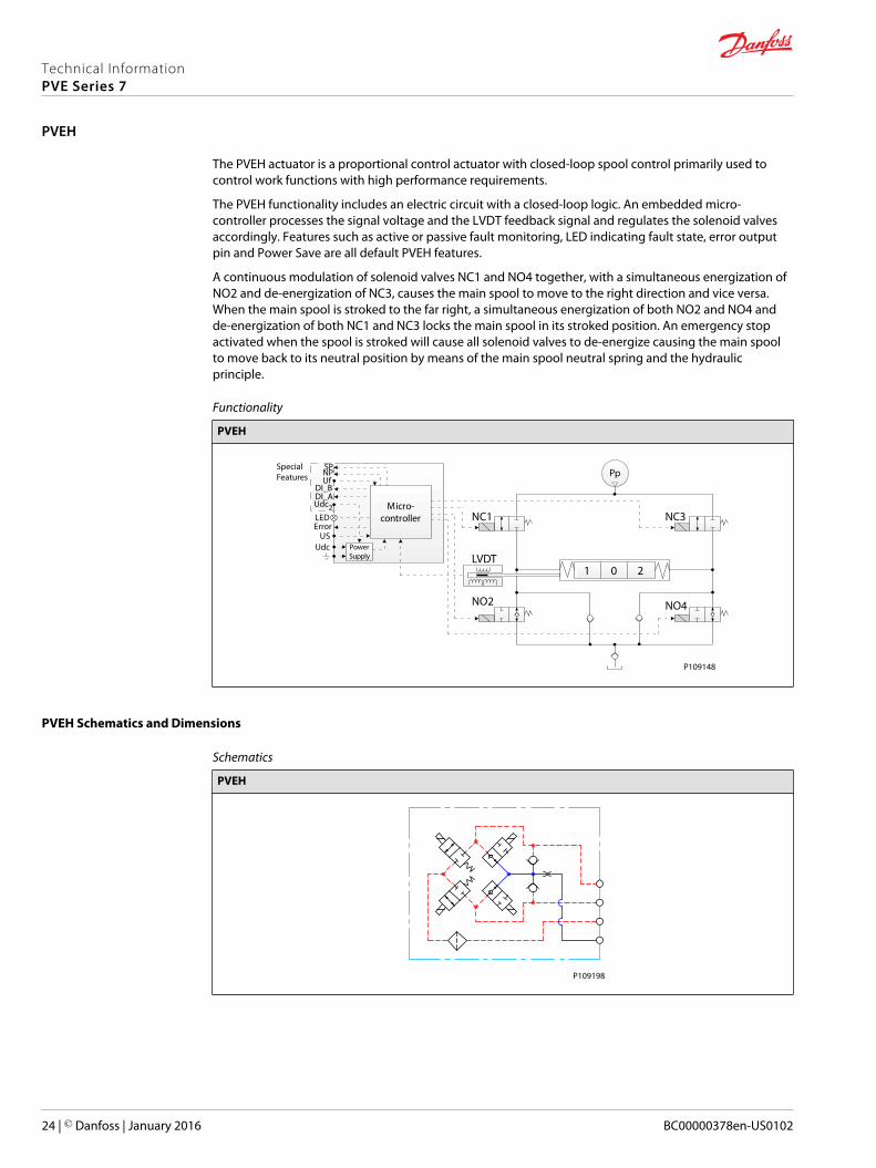
The PVEH actuator is a proportional control actuator with closed-loop spool control primarily used tocontrol work functions with high performance requirements.
The PVEH functionality includes an electric circuit with a closed-loop logic. An embedded micro-controller processes the signal voltage and the LVDT feedback signal and regulates the solenoid valvesaccordingly. Features such as active or passive fault monitoring, LED indicating fault state, error outputpin and Power Save are all default PVEH features.
A continuous modulation of solenoid valves NC1 and NO4 together, with a simultaneous energization ofNO2 and de-energization of NC3, causes the main spool to move to the right direction and vice versa.When the main spool is stroked to the far right, a simultaneous energization of both NO2 and NO4 andde-energization of both NC1 and NC3 locks the main spool in its stroked position. An emergency stopactivated when the spool is stroked will cause all solenoid valves to de-energize causing the main spoolto move back to its neutral position by means of the main spool neutral spring and the hydraulicprinciple.
Functionality
PVEH
21 0
Pp
Micro-controller
PowerSupply
US
SpecialFeatures
SPNPUf
DI_BDI_AUdc2LEDError
Udc
NC1 NC3
NO4NO2
LVDT
P109148
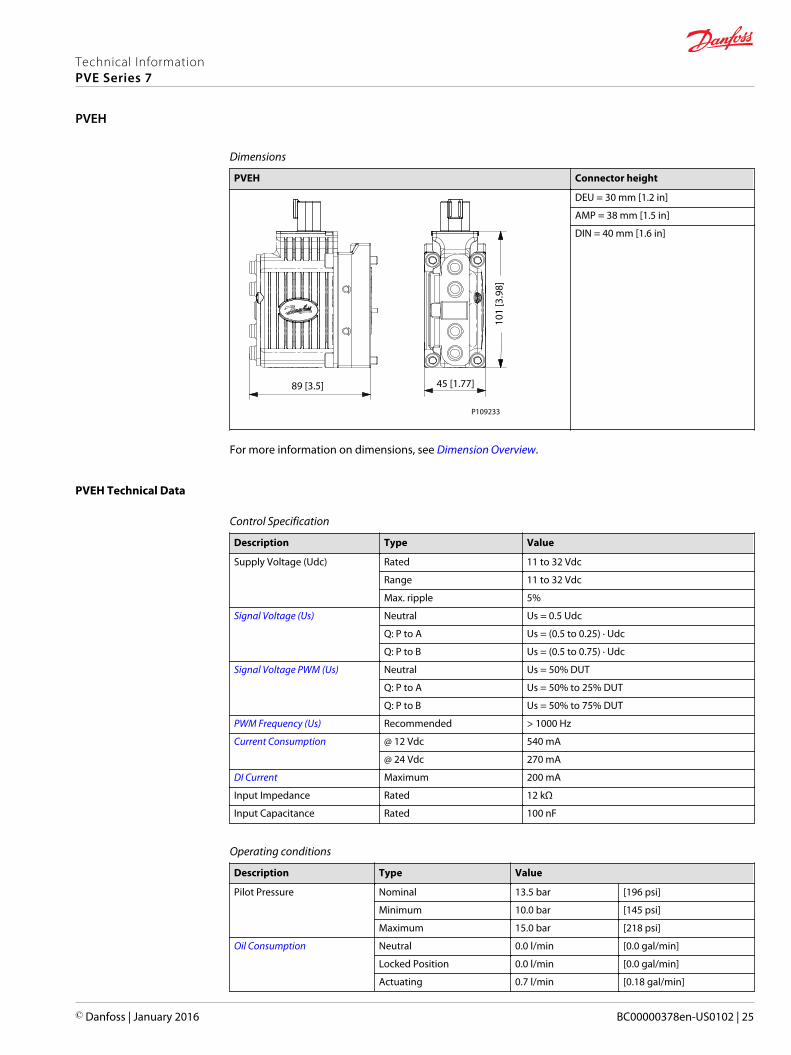
PVEH Schematics and Dimensions
Schematics
PVEH
P109198
Technical InformationPVE Series 7
PVEH
24 | © Danfoss | January 2016 BC00000378en-US0102
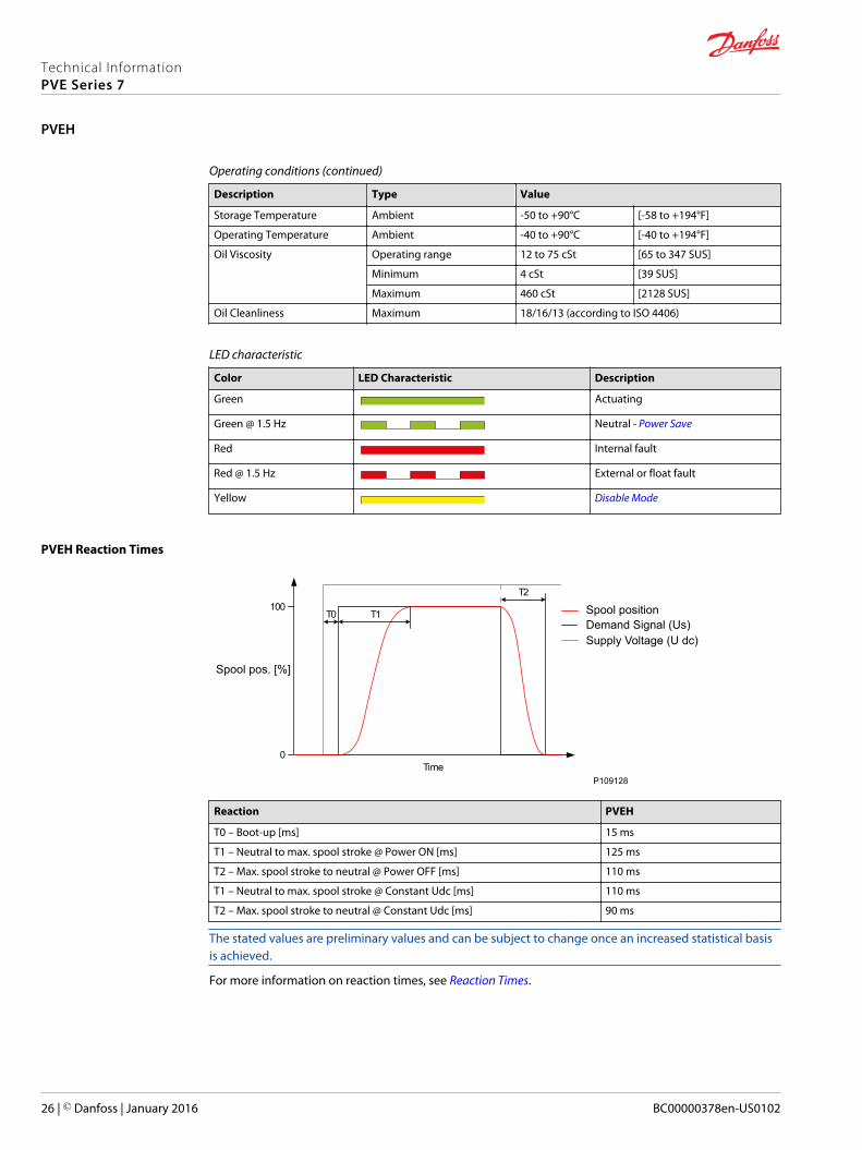
Dimensions
PVEH Connector height
101
[3.9
8]
45 [1.77]89 [3.5]
P109233
DEU = 30 mm [1.2 in]
AMP = 38 mm [1.5 in]
DIN = 40 mm [1.6 in]
For more information on dimensions, see Dimension Overview.
PVEH Technical Data
Control Specification
Description Type Value
Supply Voltage (Udc) Rated 11 to 32 Vdc
Range 11 to 32 Vdc
Max. ripple 5%
Signal Voltage (Us) Neutral Us = 0.5 Udc
Q: P to A Us = (0.5 to 0.25) ∙ Udc
Q: P to B Us = (0.5 to 0.75) ∙ Udc
Signal Voltage PWM (Us) Neutral Us = 50% DUT
Q: P to A Us = 50% to 25% DUT
Q: P to B Us = 50% to 75% DUT
PWM Frequency (Us) Recommended > 1000 Hz
Current Consumption @ 12 Vdc 540 mA
@ 24 Vdc 270 mA
DI Current Maximum 200 mA
Input Impedance Rated 12 kΩ
Input Capacitance Rated 100 nF
Operating conditions
Description Type Value
Pilot Pressure Nominal 13.5 bar [196 psi]
Minimum 10.0 bar [145 psi]
Maximum 15.0 bar [218 psi]
Oil Consumption Neutral 0.0 l/min [0.0 gal/min]
Locked Position 0.0 l/min [0.0 gal/min]
Actuating 0.7 l/min [0.18 gal/min]
Technical InformationPVE Series 7
PVEH
© Danfoss | January 2016 BC00000378en-US0102 | 25
Operating conditions (continued)
Description Type Value
Storage Temperature Ambient -50 to +90°C [-58 to +194°F]
Operating Temperature Ambient -40 to +90°C [-40 to +194°F]
Oil Viscosity Operating range 12 to 75 cSt [65 to 347 SUS]
Minimum 4 cSt [39 SUS]
Maximum 460 cSt [2128 SUS]
Oil Cleanliness Maximum 18/16/13 (according to ISO 4406)
LED characteristic
Color LED Characteristic Description
Green Actuating
Green @ 1.5 Hz Neutral - Power Save
Red Internal fault
Red @ 1.5 Hz External or float fault
Yellow Disable Mode
PVEH Reaction Times
100
0Time
T0 T1
T2
P109128
Spool positionDemand Signal (Us)Supply Voltage (U dc)
Spool pos. [%]
Reaction PVEH
T0 – Boot-up [ms] 15 ms
T1 – Neutral to max. spool stroke @ Power ON [ms] 125 ms
T2 – Max. spool stroke to neutral @ Power OFF [ms] 110 ms
T1 – Neutral to max. spool stroke @ Constant Udc [ms] 110 ms
T2 – Max. spool stroke to neutral @ Constant Udc [ms] 90 ms
The stated values are preliminary values and can be subject to change once an increased statistical basisis achieved.
For more information on reaction times, see Reaction Times.
Technical InformationPVE Series 7
PVEH
26 | © Danfoss | January 2016 BC00000378en-US0102
PVEH Hysteresis and Ripple
US [%]
100
0
Spool Position [%]
100(0.75 ∙ U dc)
BP
h
50(0.50 ∙ U dc)
vFixed pos.
Spool Position
P109146
Description Type PVEH
Hysteresis (h) Rated [%] 4
Steady state ripple @ fixed Us (v) Rated [mm] 0.0
The stated values are preliminary values and can be subject to change once an increased statistical basisis achieved.
For more information on hysteresis and ripple, see Hysteresis and Ripple.
PVEH Variants for PVG
PVG 32/100 variants
Part number Type Connector IP Fault monitoring Functionality
11166732 PVEH 1x4 DEU 67 Passive Standard
11166775 PVEH 1x4 DEU 67 Active Standard
11166825 PVEH 1x4 AMP 66 Passive Standard
11166818 PVEH 1x4 AMP 66 Active Standard
11166824 PVEH 1x4 DIN 65 Passive Standard
11166817 PVEH 1x4 DIN 65 Active Standard
111668321 PVEH-U 1x4 AMP 66 Passive Fixed US 0-10 V dc
111668211 PVEH-U 1x4 AMP 66 Active Fixed US 0-10 V dc
111667701 PVEH-U 1x4 DIN 65 Passive Fixed US 0-10 V dc
111667721 PVEH-U 1x4 DIN 65 Active Fixed US 0-10 V dc
11166840 PVEH-FLB 1x4 DEU 67 Passive Float B-port
11166742 PVEH-FLB 1x4 DEU 67 Active Float B-port
11166839 PVEH-FLB 1x4 DIN 65 Active Float B-port
111668412 PVEH-FLA 1x6 DEU 67 Active Float A-port
111687382 PVEH-FLA 1x6 AMP 66 Passive Float A-port
111687392 PVEH-FLA 1x6 AMP 66 Active Float A-port
111667733 PVEH-SP 1x6 DEU 67 Active Standard
111667504 PVEH-NP 1x6 DEU 67 Fast active Standard
Technical InformationPVE Series 7
PVEH
© Danfoss | January 2016 BC00000378en-US0102 | 27

PVG 32/100 variants (continued)
Part number Type Connector IP Fault monitoring Functionality
111668355 PVEH-DI 2x4 DEU 67 Active Standard
111668205 PVEH-DI 2x4 AMP 66 Passive Standard
111668195 PVEH-DI 2x4 AMP 66 Active Standard1 Includes Disable Mode special feature2 Includes Dedicated Float Pin (UF) special feature3 Includes Spool Position special feature4 Includes Neutral Power-Off special feature5 Includes Direction Indication special feature
PVG 120 variants
Part number Type Connector IP Fault monitoring Functionality
11166760 PVEH 1x4 DEU 67 Passive Standard
11166814 PVEH 1x4 AMP 66 Passive Standard
11166801 PVEH 1x4 AMP 66 Active Standard
11166813 PVEH 1x4 DIN 65 Passive Standard
11166777 PVEH 1x4 DIN 65 Active Standard
111667711 PVEH-U 1x4 DIN 65 Passive Fixed US 0-10 V dc
111667671 PVEH-U 1x4 DIN 65 Active Fixed US 0-10 V dc1 Includes Disable Mode special feature
PVG 128/256 variants
Part number Type Connector IP Fault monitoring Functionality
11186325 PVEH 1x4 DEU 67 Passive Standard
11186326 PVEH 1x4 DEU 67 Active Standard
11186321 PVEH 1x4 DIN 65 Passive Standard
11186322 PVEH 1x4 DIN 65 Active Standard
111863231 PVEH-U 1x4 DIN 65 Passive Fixed US 0-10 Vdc
111863241 PVEH-U 1x4 DIN 65 Active Fixed US 0-10 Vdc
111863272 PVEH-FLA 1x6 DEU 67 Active Float A-port1 Includes Disable Mode special feature2 Includes Dedicated Float Pin (UF) special feature
PVG 60 variants
Part number Type Connector IP Fault monitoring Functionality
11166910 PVEH 1x4 DIN 65 Active Float B-port
Technical InformationPVE Series 7
PVEH
28 | © Danfoss | January 2016 BC00000378en-US0102

The PVES actuator is a proportional control actuator with closed-loop spool control primarily used tocontrol work functions with very high performance requirements.
The PVES functionality includes an electric circuit with a closed-loop logic. An embedded micro-controllerprocesses the signal voltage and the LVDT feedback signal and regulates the solenoid valves accordingly.Features such as active or passive fault monitoring, LED indicating fault state, error output pin and PowerSave are all default PVEH features.
A continuous modulation of solenoid valves NC1 and NO4 together with a simultaneous energization ofNO2 and de-energization of NC3 causes the main spool to move to the right direction and vice versa.When the main spool is stroked to the far right, a simultaneous energization of both NO2 and NO4 andde-energization of both NC1 and NC3 balances the main spool in its stroked position. An emergency stopactivated when the spool is stroked will cause all solenoid valves to de-energize causing the main spoolto move back to its neutral position by means of the main spool neutral spring and the hydraulicprinciple.
Functionality
PVES
21 0
Pp
Micro-controller
PowerSupply
SpecialFeatures
SP
LEDError
UsUdc
NC1 NC3
NO2 NO4
LVDT
P109149
PVES Schematics and Dimensions
Schematic
PVES
P109199
Technical InformationPVE Series 7
PVES
© Danfoss | January 2016 BC00000378en-US0102 | 29

Dimensions
PVES Connector height
101 [3.98]
45 [1.77]89 [3.5]
P109235
DEU = 30 mm [1.2 in]
AMP = 38 mm [1.5 in]
DIN = 40 mm [1.6 in]
For information on dimensions, see Dimension Overview.
PVES Technical Data
Control Specification
Description Type Value
Supply Voltage (Udc) Rated 11 to 32 Vdc
Range 11 to 32 Vdc
Max. ripple 5%
Signal Voltage (Us) Neutral Us = 0.5 Udc
Q: P to A Us = (0.5 to 0.25) ∙ Udc
Q: P to B Us = (0.5 to 0.75) ∙ Udc
Signal Voltage PWM (Us) Neutral Us = 50% DUT
Q: P to A Us = 50% to 25% DUT
Q: P to B Us = 50% to 75% DUT
PWM Frequency (Us) Recommended > 1000 Hz
Current Consumption @ 12 Vdc 560 mA
@ 24 Vdc 280 mA
Input Impedance Rated 12 kΩ
Input Capacitance Rated 100 nF
Operating Conditions
Description Type Value
Pilot Pressure Nominal 13.5 bar [196 psi]
Minimum 10.0 bar [145 psi]
Maximum 15.0 bar [220 psi]
Oil Consumption Neutral 0.3 l/min [0.0 gal/min]
Locked Position 0.1 l/min [0.0 gal/min]
Actuating 0.8 l/min [0.24 gal/min]
Technical InformationPVE Series 7
PVES
30 | © Danfoss | January 2016 BC00000378en-US0102

Operating Conditions (continued)
Description Type Value
Storage Temperature Ambient -50 to +90°C [-58 to +194°F]
Operating Temperature Ambient -40 to +90°C [-40 to +194°F]
Oil Viscosity Recommended 12 to 75 cSt [65 to 347 SUS]
Minimum 4 cSt [39 SUS]
Maximum 460 cSt [2128 SUS]
Oil Cleanliness Maximum 18/16/13 (according to ISO 4406)
LED Characteristic
Color LED Characteristic Description
Green Actuating
Green @ 1.5 Hz Neutral - Power Save
Red Internal fault
Red @ 1.5 Hz External or float fault
Yellow Disable Mode
PVES Reaction Times
100
0Time
T0 T1
T2
P109128
Spool positionDemand Signal (Us)Supply Voltage (U dc)
Spool pos. [%]
Reaction PVES
T0 – Boot-up [ms] 15
T1 – Neutral to max. spool stroke @ Power ON [ms] 125
T2 – Max. spool stroke to neutral @ Power OFF [ms] 110
T1 – Neutral to max. spool stroke @ Constant UDC [ms] 110
T2 – Max. spool stroke to neutral @ Constant UDC [ms] 90
The stated values are preliminary values and can be subject to change once an increased statistical basisis achieved.
For more information on reaction time, see Reaction Times on page 49
Technical InformationPVE Series 7
PVES
© Danfoss | January 2016 BC00000378en-US0102 | 31

PVES Hysteresis and Ripple
US [%]
100
0
Spool Position [%]
100(0.75 ∙ U dc)
BP
h
50(0.50 ∙ U dc)
vFixed pos.
Spool Position
P109146
Description Type PVES
Hysteresis (h) Rated [%] <0.5
Steady state ripple @ fixed US (v) Rated [mm] 0.2
The stated values are preliminary values and can be subject to change once an increased statistical basisis achieved.
For more information on hysteresis and ripple, see Hysteresis and Ripple.
PVES Variants for PVG
PVG 32/100 variants
Part number Type Connector IP Fault monitoring Functionality
11166748 PVES 1x4 DEU 67 Passive Standard
11166864 PVES 1x4 DEU 67 Active Standard
11166859 PVES 1x4 AMP 66 Passive Standard
11166858 PVES 1x4 AMP 66 Active Standard
11166849 PVES 1x4 DIN 65 Passive Standard
11166857 PVES 1x4 DIN 65 Active Standard
111667451 PVES-U 1x4 DEU 67 Passive Fixed Us 0-10 Vdc
111667471 PVES-U 1x4 AMP 66 Active Fixed Us 0-10 Vdc
111667522 PVES-SP 1x6 DEU 67 Passive Standard1 Includes Disable Mode special feature2 Includes Spool Position special feature
PVG 120 variants
Part number Type Connector IP Fault monitoring Functionality
11166761 PVES 1x4 DEU 67 Passive Standard
11166762 PVES 1x4 DIN 65 Passive Standard
Technical InformationPVE Series 7
PVES
32 | © Danfoss | January 2016 BC00000378en-US0102
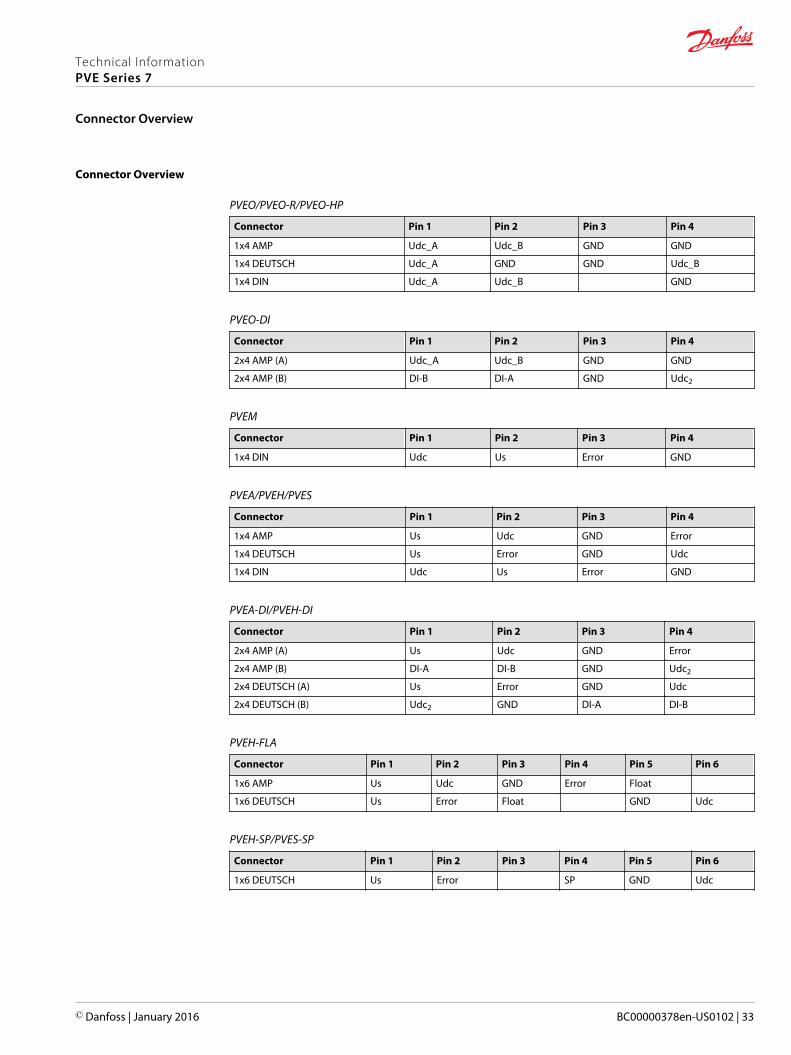
Connector Overview
PVEO/PVEO-R/PVEO-HP
Connector Pin 1 Pin 2 Pin 3 Pin 4
1x4 AMP Udc_A Udc_B GND GND
1x4 DEUTSCH Udc_A GND GND Udc_B
1x4 DIN Udc_A Udc_B GND
PVEO-DI
Connector Pin 1 Pin 2 Pin 3 Pin 4
2x4 AMP (A) Udc_A Udc_B GND GND
2x4 AMP (B) DI-B DI-A GND Udc2
PVEM
Connector Pin 1 Pin 2 Pin 3 Pin 4
1x4 DIN Udc Us Error GND
PVEA/PVEH/PVES
Connector Pin 1 Pin 2 Pin 3 Pin 4
1x4 AMP Us Udc GND Error
1x4 DEUTSCH Us Error GND Udc
1x4 DIN Udc Us Error GND
PVEA-DI/PVEH-DI
Connector Pin 1 Pin 2 Pin 3 Pin 4
2x4 AMP (A) Us Udc GND Error
2x4 AMP (B) DI-A DI-B GND Udc2
2x4 DEUTSCH (A) Us Error GND Udc
2x4 DEUTSCH (B) Udc2 GND DI-A DI-B
PVEH-FLA
Connector Pin 1 Pin 2 Pin 3 Pin 4 Pin 5 Pin 6
1x6 AMP Us Udc GND Error Float
1x6 DEUTSCH Us Error Float GND Udc
PVEH-SP/PVES-SP
Connector Pin 1 Pin 2 Pin 3 Pin 4 Pin 5 Pin 6
1x6 DEUTSCH Us Error SP GND Udc
Technical InformationPVE Series 7
Connector Overview
© Danfoss | January 2016 BC00000378en-US0102 | 33
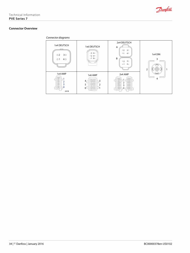
Connector diagrams
1x4 DEUTSCH
2 3
41
1x6 DEUTSCH
123 4
56
2x4 DEUTSCH
3
412
1
2 3
4
A
B
1x4 DIN
1 2
3
4
1x4 AMP
2418
1234
1x6 AMP
1234
56
2x4 AMP
1234
Technical InformationPVE Series 7
Connector Overview
34 | © Danfoss | January 2016 BC00000378en-US0102
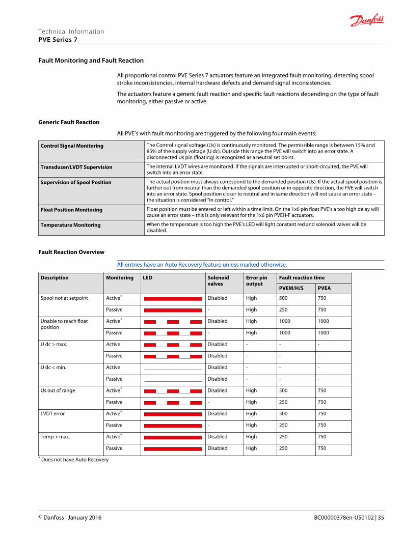
All proportional control PVE Series 7 actuators feature an integrated fault monitoring, detecting spoolstroke inconsistencies, internal hardware defects and demand signal inconsistencies.
The actuators feature a generic fault reaction and specific fault reactions depending on the type of faultmonitoring, either passive or active.
Generic Fault Reaction
All PVE’s with fault monitoring are triggered by the following four main events:
Control Signal Monitoring The Control signal voltage (Us) is continuously monitored. The permissible range is between 15% and85% of the supply voltage (U dc). Outside this range the PVE will switch into an error state. Adisconnected Us pin (floating) is recognized as a neutral set point.
Transducer/LVDT Supervision The internal LVDT wires are monitored. If the signals are interrupted or short-circuited, the PVE willswitch into an error state.
Supervision of Spool Position The actual position must always correspond to the demanded position (Us). If the actual spool position isfurther out from neutral than the demanded spool position or in opposite direction, the PVE will switchinto an error state. Spool position closer to neutral and in same direction will not cause an error state –the situation is considered “in control.”
Float Position Monitoring Float position must be entered or left within a time limit. On the 1x6 pin float PVE’s a too high delay willcause an error state – this is only relevant for the 1x6 pin PVEH-F actuators.
Temperature Monitoring When the temperature is too high the PVE's LED will light constant red and solenoid valves will bedisabled.
Fault Reaction Overview
All entries have an Auto Recovery feature unless marked otherwise.
Description Monitoring LED Solenoidvalves
Error pinoutput
Fault reaction time
PVEM/H/S PVEA
Spool not at setpoint Active* Disabled High 500 750
Passive - High 250 750
Unable to reach floatposition
Active* Disabled High 1000 1000
Passive - High 1000 1000
U dc > max. Active Disabled - - -
Passive Disabled - - -
U dc < min. Active Disabled - - -
Passive Disabled - - -
Us out of range Active* Disabled High 500 750
Passive - High 250 750
LVDT error Active* Disabled High 500 750
Passive - High 250 750
Temp > max. Active* Disabled High 250 750
Passive Disabled High 250 750
* Does not have Auto Recovery
Technical InformationPVE Series 7
Fault Monitoring and Fault Reaction
© Danfoss | January 2016 BC00000378en-US0102 | 35
Standard and Fixed US 0-10 Vdc
All standard proportional actuator variants (PVEM/PVEA/PVEH/PVES) can be controlled by an analogsignal voltage (Us) or a PWM controlled signal voltage (Us) proportional to the supply voltage (Udc).
The PVEH-U and PVES-U variants are controlled by a fixed 0-10 Vdc signal voltage (Us), directlycompatible with standard PLC control.
PVEO
Description Type Value
Supply voltage (Udc) Rated 12 Vdc 24 Vdc
Range 11 to 15 Vdc 22 to 30 Vdc
Max. ripple 5%
PVEM/PVEA/PVEH/PVES
Description Type Value
Supply voltage (Udc) Rated 11 to 32 Vdc
Range 11 to 32 Vdc
Max. ripple 5%
Signal voltage (Us) Neutral Us = 0.5 ∙ Udc
Q: P to A US = (0.5 to 0.25) ∙ Udc
Q: P to B US = (0.5 to 0.75) ∙ Udc
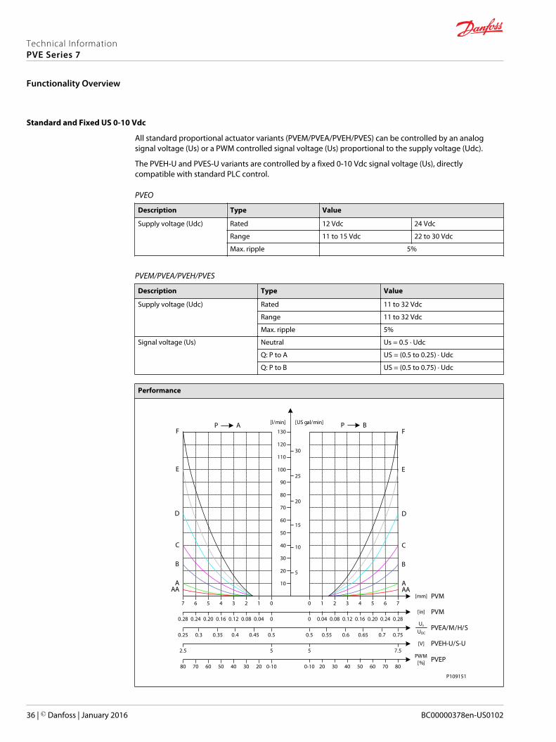
Performance
[mm] PVM
BP
0 1 2 3 4 5 6 7
AP
[in] PVM00.040.080.120.160.200.240.28 0 0.04 0.08 0.12 0.16 0.20 0.24 0.28
PVEA/M/H/S0.50.450.40.350.30.25
Us
UDC0.5 0.55 0.6 0.65 0.7 0.75
PWM[%] PVEP
0-1020304050607080 0-10 20 30 40 50 60 70 80
PVEH-U/S-U52.5 5 7.5
[V]
AAA
B
C
D
E
F
AAA
B
C
D
E
F
10
20
30
40
50
60
70
80
90
100
110
120
130
5
10
15
20
25
30
[l/min] [US gal/min]
01234567
P109151
Technical InformationPVE Series 7
Functionality Overview
36 | © Danfoss | January 2016 BC00000378en-US0102
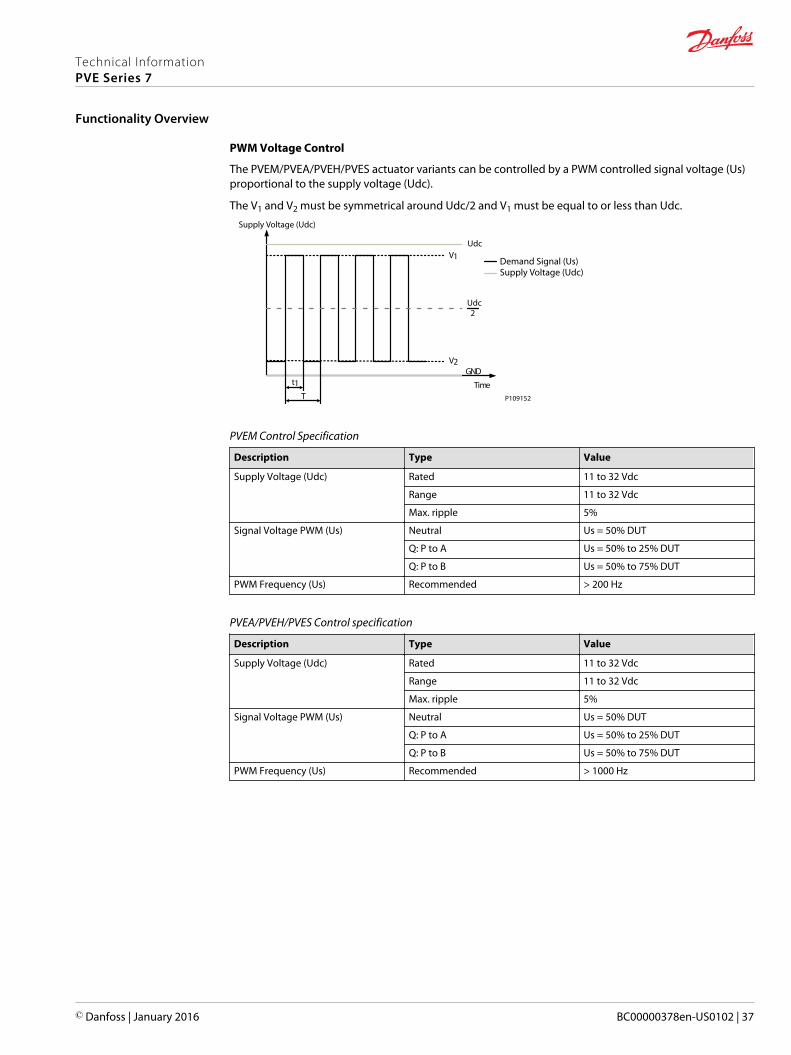
PWM Voltage Control
The PVEM/PVEA/PVEH/PVES actuator variants can be controlled by a PWM controlled signal voltage (Us)proportional to the supply voltage (Udc).
The V1 and V2 must be symmetrical around Udc/2 and V1 must be equal to or less than Udc.
Time
Udc
Udc2
GND
V1
V2
t1T P109152
Demand Signal (Us)Supply Voltage (Udc)
Supply Voltage (Udc)
PVEM Control Specification
Description Type Value
Supply Voltage (Udc) Rated 11 to 32 Vdc
Range 11 to 32 Vdc
Max. ripple 5%
Signal Voltage PWM (Us) Neutral Us = 50% DUT
Q: P to A Us = 50% to 25% DUT
Q: P to B Us = 50% to 75% DUT
PWM Frequency (Us) Recommended > 200 Hz
PVEA/PVEH/PVES Control specification
Description Type Value
Supply Voltage (Udc) Rated 11 to 32 Vdc
Range 11 to 32 Vdc
Max. ripple 5%
Signal Voltage PWM (Us) Neutral Us = 50% DUT
Q: P to A Us = 50% to 25% DUT
Q: P to B Us = 50% to 75% DUT
PWM Frequency (Us) Recommended > 1000 Hz
Technical InformationPVE Series 7
Functionality Overview
© Danfoss | January 2016 BC00000378en-US0102 | 37
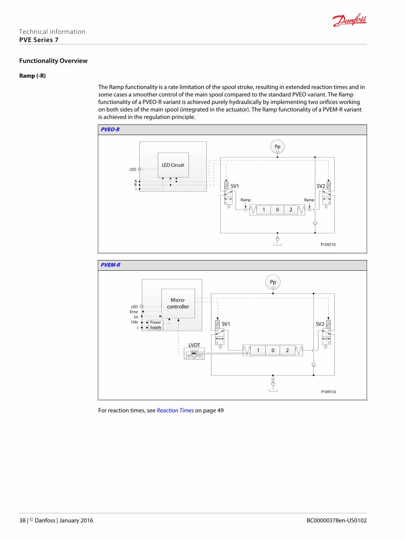
Ramp (-R)
The Ramp functionality is a rate limitation of the spool stroke, resulting in extended reaction times and insome cases a smoother control of the main spool compared to the standard PVEO variant. The Rampfunctionality of a PVEO-R variant is achieved purely hydraulically by implementing two orifices workingon both sides of the main spool (integrated in the actuator). The Ramp functionality of a PVEM-R variantis achieved in the regulation principle.
PVEO-R
21 0
Pp
LED CircuitLED
AB
Ramp Ramp
SV1 SV2
P109210
PVEM-R
21 0
Pp
LVDT
SV2SV1
Micro-controller
PowerSupply
LEDError
UsUdc
P109153
For reaction times, see Reaction Times on page 49
Technical InformationPVE Series 7
Functionality Overview
38 | © Danfoss | January 2016 BC00000378en-US0102

Quick Reaction (-Q)
The Quick Reaction functionality of the PVEM-Q variant results in shorter reaction times and a more rapidor aggressive control of the main spool compared to the standard PVEM variant. The Quick Reactionfunctionality of a PVEM-Q is achieved by replacing the combined orifice and check valve with a checkvalve in the connection to tank and changing the regulation principle.
PVEM-Q
21 0
Pp
LVDT
SV2SV1
Micro-controller
PowerSupply
UDC
US
ErrorLED
For reaction times, see Reaction Times on page 49.
Technical InformationPVE Series 7
Functionality Overview
© Danfoss | January 2016 BC00000378en-US0102 | 39

Float B-Port (-FLB)
The Float B-Port functionality enables the proportional PVEM-FLB/PVEH-FLB actuator variants to enter themain spool into a float position. The PVE actuators with Float B-Port functionality is compatible with thededicated main spools with electronic float in B-port.
PVE Type PVBS Type Standard Flow Control Float Control
PVEM-FLB (1x4 pin) Deadband 1.5 mm Us = (0.35 → 0.65) ∙ Udc Us = 0.75 ∙ Udc
PVEH-FLB (1x4 pin) Max. B-port flow 4.8 mm
[mm] PVM
BP
0 1 2 3 4 5 6 7
10
20
30
40
50
60
70
80
90
100
110
120
130
5
10
15
20
25
30
[l/min] [US gal/min]
[in] PVM0 0.04 0.08 0.12 0.16 0.20 0.24 0.28
PVEM-FLB/H-FLBUs
UDC0.5 0.55 0.6 0.65 0.7
AA
A
B
C
D
E
8
0.31
0.75
P109155
Technical InformationPVE Series 7
Functionality Overview
40 | © Danfoss | January 2016 BC00000378en-US0102
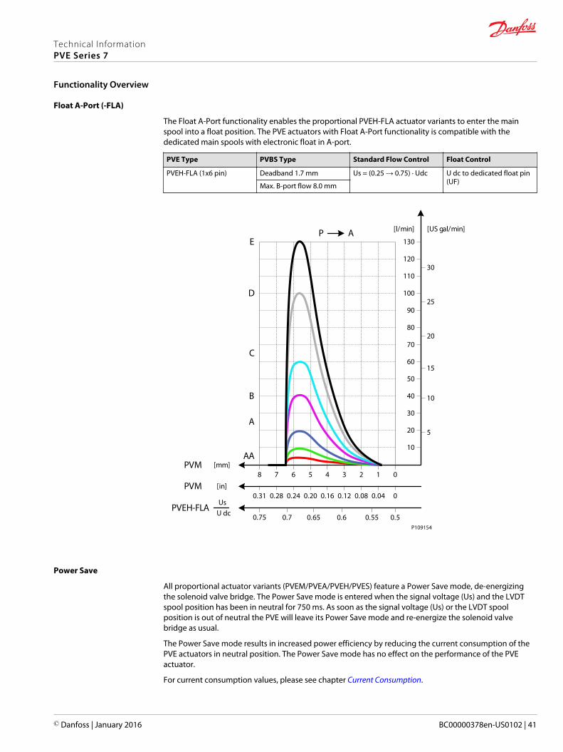
Float A-Port (-FLA)
The Float A-Port functionality enables the proportional PVEH-FLA actuator variants to enter the mainspool into a float position. The PVE actuators with Float A-Port functionality is compatible with thededicated main spools with electronic float in A-port.
PVE Type PVBS Type Standard Flow Control Float Control
PVEH-FLA (1x6 pin) Deadband 1.7 mm Us = (0.25 → 0.75) ∙ Udc U dc to dedicated float pin(UF)Max. B-port flow 8.0 mm
AA
A
B
C
D
EAP
10
20
30
40
50
60
70
80
90
100
110
120
130
5
10
15
20
25
30
[l/min] [US gal/min]
[mm]PVM01234567
[in]PVM00.040.080.120.160.200.240.28
PVEH-FLAUs
U dc 0.50.550.60.650.7
8
0.31
0.75P109154
Power Save
All proportional actuator variants (PVEM/PVEA/PVEH/PVES) feature a Power Save mode, de-energizingthe solenoid valve bridge. The Power Save mode is entered when the signal voltage (Us) and the LVDTspool position has been in neutral for 750 ms. As soon as the signal voltage (Us) or the LVDT spoolposition is out of neutral the PVE will leave its Power Save mode and re-energize the solenoid valvebridge as usual.
The Power Save mode results in increased power efficiency by reducing the current consumption of thePVE actuators in neutral position. The Power Save mode has no effect on the performance of the PVEactuator.
For current consumption values, please see chapter Current Consumption.
Technical InformationPVE Series 7
Functionality Overview
© Danfoss | January 2016 BC00000378en-US0102 | 41

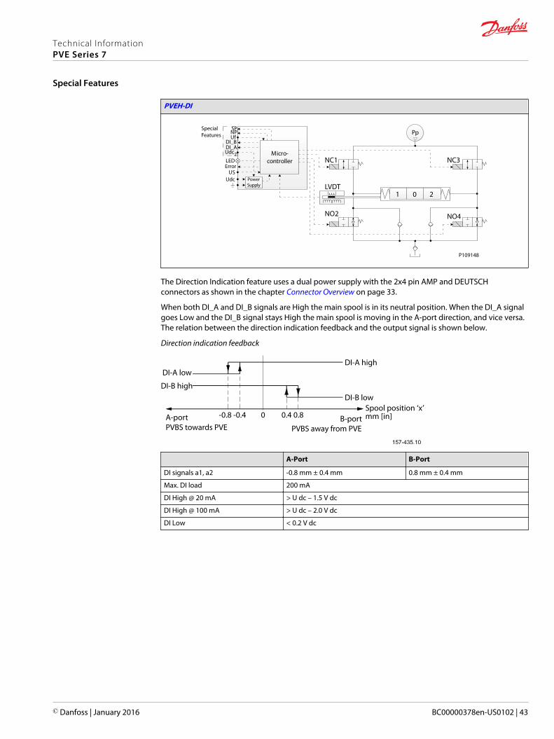
Direction Indication (-DI)
The PVEO-DI/PVEA-DI/PVEH-DI actuator variants feature an integrated Direction Indication outputderived from the LVDT spool position, indicating the state of the main spool (neutral, A-port or B-port).
PVEO-DI
21 0
Pp
LVDT
LED Circuit /Microcontroller
PowerSupply
PVEO-DI
AB
DI_BDI_A
LED
Udc
Ramp Ramp
SV1 SV2
P109126
PVEA-DI
21 0
Pp
Micro-controller
PowerSupply
NPDI_BDI_AUdc
LEDError
UsUdc
2
SpecialFeatures
NC1 NC3
LVDT
P109147
Technical InformationPVE Series 7
Special Features
42 | © Danfoss | January 2016 BC00000378en-US0102
PVEH-DI
21 0
Pp
Micro-controller
PowerSupply
US
SpecialFeatures
SPNPUf
DI_BDI_AUdc2LEDError
Udc
NC1 NC3
NO4NO2
LVDT
P109148
The Direction Indication feature uses a dual power supply with the 2x4 pin AMP and DEUTSCHconnectors as shown in the chapter Connector Overview on page 33.
When both DI_A and DI_B signals are High the main spool is in its neutral position. When the DI_A signalgoes Low and the DI_B signal stays High the main spool is moving in the A-port direction, and vice versa.The relation between the direction indication feedback and the output signal is shown below.
Direction indication feedback
DI-A low
DI-B high
DI-A high
DI-B lowSpool position ‘x’ mm [in]B-port
PVBS away from PVEA-portPVBS towards PVE
0.4 0.8-0.8 -0.4 0
A-Port B-Port
DI signals a1, a2 -0.8 mm ± 0.4 mm 0.8 mm ± 0.4 mm
Max. DI load 200 mA
DI High @ 20 mA > U dc – 1.5 V dc
DI High @ 100 mA > U dc – 2.0 V dc
DI Low < 0.2 V dc
Technical InformationPVE Series 7
Special Features
© Danfoss | January 2016 BC00000378en-US0102 | 43

Dedicated Float Pin (UF)
The Dedicated Float Pin (UF) feature is related to the PVEH-FLA actuator variant described in the chapter Float A-Port. The PVEH-FLA uses 1x6 pin AMP or DEUTSCH connectors, as shown in the chapter ConnectorOverview, enabling the user to move the main spool into its float position by powering a dedicated floatpin (UF).
PVEH-FLA
21 0
Pp
Micro-controller
PowerSupply
US
SpecialFeatures
SPNPUf
DI_BDI_AUdc2LEDError
Udc
NC1 NC3
NO4NO2
LVDT
P109148
Dedicated Float Pin (UF) Specification
Low or not connected Normal operation
High Float
Input range Udc
Max. voltage 32 Vdc
Technical InformationPVE Series 7
Special Features
44 | © Danfoss | January 2016 BC00000378en-US0102

Spool Position (-SP)
The Spool Position (SP) feature available in the PVEH-SP/PVES-SP actuator variants enables the user toderive the position of the main spool by means of an analog voltage signal on the dedicated spoolposition (SP) output pin. The spool position output is derived from the LVDT spool position. The PVEH-SP/PVES-SP uses a 1x6 DEUTSCH connector. For more information on connectors, please see the chapter Connector Overview on page 33.
PVEH-SP
21 0
Pp
Micro-controller
PowerSupply
US
SpecialFeatures
SPNPUf
DI_BDI_AUdc2LEDError
Udc
NC1 NC3
NO4NO2
LVDT
P109148
PVES-SP
21 0
Pp
Micro-controller
PowerSupply
SpecialFeatures
SP
LEDError
UsUdc
NC1 NC3
NO2 NO4
LVDT
P109149
Technical InformationPVE Series 7
Special Features
© Danfoss | January 2016 BC00000378en-US0102 | 45

Spool position feedback (-SP)
Spool travelSpool travel0.5V
7 mm100%B port
7 mm100%A port
0 mmNeutral
2.5V
4.5V
UspUs
Us
Us
Usp
Usp25% UDC
50% UDC
75% UDC
The Spool Position (SP) feedback signal is a 0.5 Vdc to 4.0 Vdc signal, inverted in direction relative to Uswith 2.5 Vdc as the neutral value.
A-Port B-Port
Spool position Neutral to max. stroke [mm] Neutral to max. stroke [mm]
Max. SP load 0.5 mA
Output range 2.5 – 1.25 Vdc 2.5 – 3.75 Vdc
Technical InformationPVE Series 7
Special Features
46 | © Danfoss | January 2016 BC00000378en-US0102

Neutral Power-OFF (-NP)
The Neutral Power-OFF (NP) feature available in the PVEA-NP/PVEH-NP actuator variants enables the userto identify whether the solenoid valves in the actuator are energized or de-energized via a dedicatedneutral power-OFF (NP) output pin. The PVEA-NP/PVEH-NP uses a 1x6 DEUTSCH connector. For moreinformation on connectors, please see the chapter Connector Overview on page 33.
PVEA-NP
21 0
Pp
Micro-controller
PowerSupply
NPDI_BDI_AUdc
LEDError
UsUdc
2
SpecialFeatures
NC1 NC3
LVDT
P109147
PVEH-NP
21 0
Pp
Micro-controller
PowerSupply
US
SpecialFeatures
SPNPUf
DI_BDI_AUdc2LEDError
Udc
NC1 NC3
NO4NO2
LVDT
P109148
The Neutral Power-OFF (NP) signal is defined as shown below.
Solenoid disabling function (-NP) curves
UDC
US
Ground
Sfb
Neutral Power-OFF (NP) Specification
Normal operation > Udc to 2 Vdc
Power Save < 1 Vdc (solenoid valves de-energized)
Max. NP load 50 mA
Technical InformationPVE Series 7
Special Features
© Danfoss | January 2016 BC00000378en-US0102 | 47

Disable Mode
The PVEH-U/PVES-U actuator variants controlled by a fixed 0-10 Vdc signal voltage (Us), feature the abilityto enter a disable mode, deactivating the counteracting force on the main spool created by the solenoidvalve bridge, when using manual override (hand operational mode). The disable mode is entered bysending a signal voltage (Us) of 16.2% of 10 Vdc when in Power Save.
For more information, please see Power Save.
Technical InformationPVE Series 7
Special Features
48 | © Danfoss | January 2016 BC00000378en-US0102

Reaction Times
100
0Time
T0 T1
T2
P109128
Spool positionDemand Signal (Us)Supply Voltage (U dc)
Spool pos. [%]
Reaction
T0 – Boot-up [ms]
T1 – Neutral to max. spool stroke
T2 – Max. spool stroke to neutral
T1 – Neutral to max. spool stroke
T2 – Max. spool stroke to neutral
PVG 32/100 reaction times
Reaction PVEO PVEO-R PVEO-HP PVEM PVEM-R
T0 [ms] 0 0 0 15 15
T1 @ Power ON [ms] 110 300 90 225 325
T2 @ Power OFF [ms] 110 110 70 110 110
T1 @ Constant U dc [ms] 110 300 90 210 310
T2 @ Constant U dc [ms] 110 110 70 90 90
PVG 32/100 reaction times (continued)
Reaction PVEM-Q PVEA PVEH PVES
T0 [ms] 15 15 15 15
T1 @ Power ON [ms] 125 280 125 125
T2 @ Power OFF [ms] 110 200 110 110
T1 @ Constant U dc [ms] 110 265 110 110
T2 @ Constant U dc [ms] 90 200 90 90
PVG 128/256 reaction times
Reaction PVEO PVEH
T0 [ms] 0 ms 80 ms
T1 @ Power ON [ms] 320 ms 350 ms
T2 @ Power OFF [ms] 350 ms 380 ms
T1 @ Constant U dc [ms] 320 ms 320 ms
T2 @ Constant U dc [ms] 350 ms 350 ms
The stated values are preliminary values and can be subject to change once an increased statistical basisis achieved.
Technical InformationPVE Series 7
Performance Overview
© Danfoss | January 2016 BC00000378en-US0102 | 49

Hysteresis and Ripple
US [%]
100
0
Spool Position [%]
100(0.75 ∙ U dc)
BP
h
50(0.50 ∙ U dc)
vFixed pos.
Spool Position
P109146
Type Hysteresis (h) Steady state ripple @ fixed Us (v)
Rated [%] Rated [mm]
PVEM 15 0.0
PVEM-R 15 0.0
PVEM-Q 15 0.0
PVEA 2 0.3
PVEH 4 0.0
PVEH 256 1.5 0.0
PVES 0 0.2
The stated values are preliminary values and can be subject to change once an increased statistical basisis achieved.
Current Consumption
Type Typical Minimum Maximum
[mA]
PVEO @ 12 Vdc 480 430 950
PVEO @ 24 Vdc 250 220 480
PVEO-HP @ 12 Vdc 750 660 1460
PVEO-HP @ 24 Vdc 380 340 740
Type @ 12 Vdc @ 24 Vdc
[mA]
PVEM 690 350
PVEA 290 150
PVEH 540 270
PVES 560 280
The stated values are preliminary values and can be subject to change once an increased statistical basisis achieved.
Technical InformationPVE Series 7
Performance Overview
50 | © Danfoss | January 2016 BC00000378en-US0102
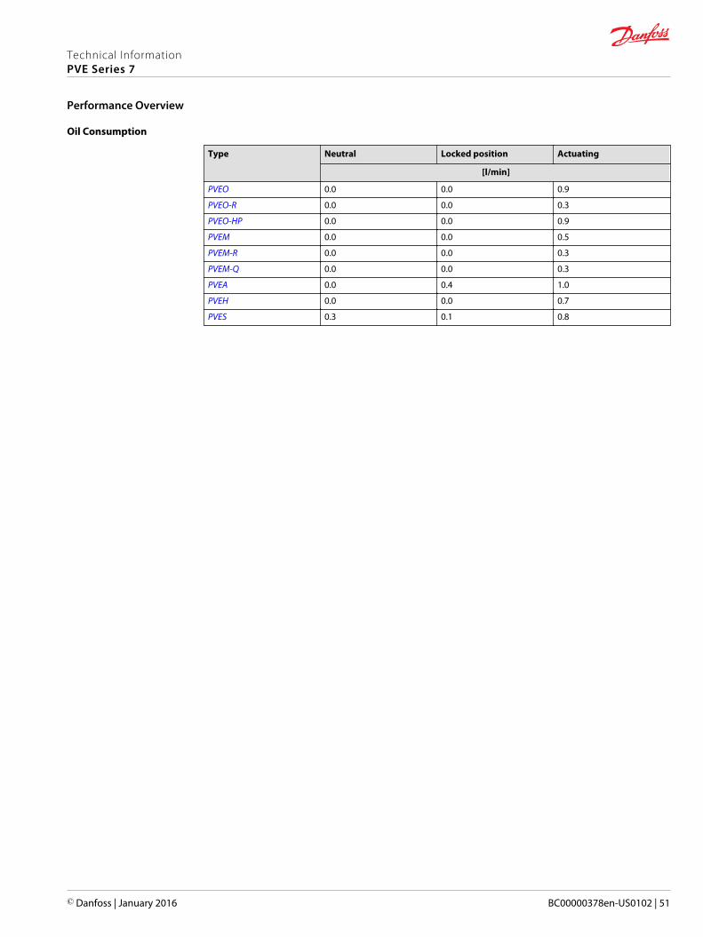
Oil Consumption
Type Neutral Locked position Actuating
[l/min]
PVEO 0.0 0.0 0.9
PVEO-R 0.0 0.0 0.3
PVEO-HP 0.0 0.0 0.9
PVEM 0.0 0.0 0.5
PVEM-R 0.0 0.0 0.3
PVEM-Q 0.0 0.0 0.3
PVEA 0.0 0.4 1.0
PVEH 0.0 0.0 0.7
PVES 0.3 0.1 0.8
Technical InformationPVE Series 7
Performance Overview
© Danfoss | January 2016 BC00000378en-US0102 | 51
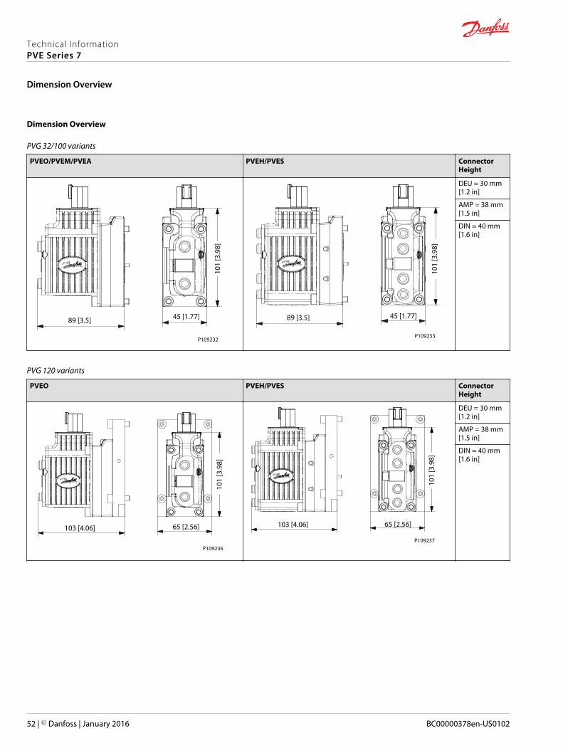
Dimension Overview
PVG 32/100 variants
PVEO/PVEM/PVEA PVEH/PVES ConnectorHeight
101
[3.9
8]
45 [1.77]89 [3.5]
P109232
101
[3.9
8]
45 [1.77]89 [3.5]
P109233
DEU = 30 mm[1.2 in]
AMP = 38 mm[1.5 in]
DIN = 40 mm[1.6 in]
PVG 120 variants
PVEO PVEH/PVES ConnectorHeight
101
[3.9
8]
65 [2.56]103 [4.06]
P109236
101
[3.9
8]
65 [2.56]103 [4.06]
P109237
DEU = 30 mm[1.2 in]
AMP = 38 mm[1.5 in]
DIN = 40 mm[1.6 in]
Technical InformationPVE Series 7
Dimension Overview
52 | © Danfoss | January 2016 BC00000378en-US0102
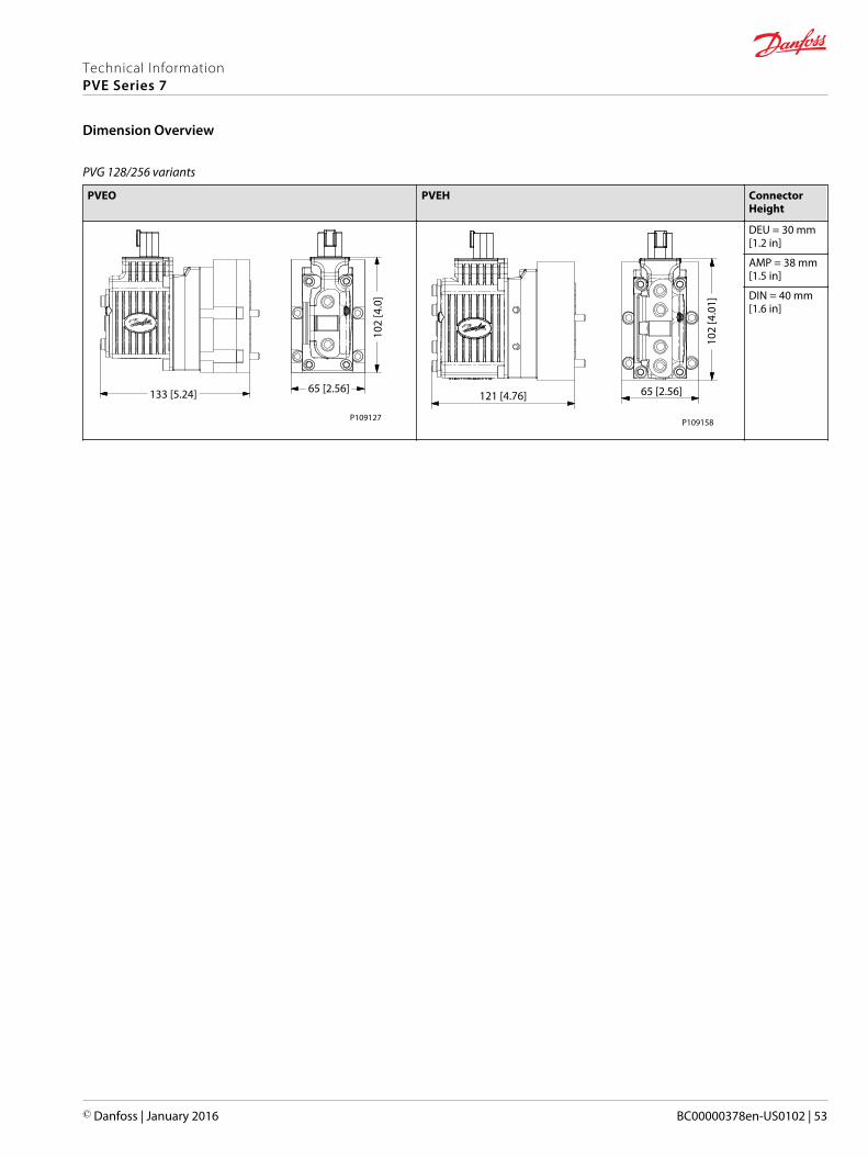
PVG 128/256 variants
PVEO PVEH ConnectorHeight
133 [5.24] 65 [2.56]10
2 [4
.0]
P109127
102
[4.0
1]
65 [2.56]121 [4.76]
P109158
DEU = 30 mm[1.2 in]
AMP = 38 mm[1.5 in]
DIN = 40 mm[1.6 in]
Technical InformationPVE Series 7
Dimension Overview
© Danfoss | January 2016 BC00000378en-US0102 | 53

Technical InformationPVE Series 7
54 | © Danfoss | January 2016 BC00000378en-US0102

Technical InformationPVE Series 7
© Danfoss | January 2016 BC00000378en-US0102 | 55
Danfoss Power Solutions is a global manufacturer and supplier of high-quality hydraulic andelectronic components. We specialize in providing state-of-the-art technology and solutionsthat excel in the harsh operating conditions of the mobile off-highway market. Building onour extensive applications expertise, we work closely with our customers to ensureexceptional performance for a broad range of off-highway vehicles.
We help OEMs around the world speed up system development, reduce costs and bringvehicles to market faster.
Danfoss – Your Strongest Partner in Mobile Hydraulics.
Go to www.powersolutions.danfoss.com for further product information.
Wherever off-highway vehicles are at work, so is Danfoss. We offer expert worldwide supportfor our customers, ensuring the best possible solutions for outstanding performance. Andwith an extensive network of Global Service Partners, we also provide comprehensive globalservice for all of our components.
Please contact the Danfoss Power Solution representative nearest you.
Local address:
Danfoss Power Solutions GmbH & Co. OHGKrokamp 35D-24539 Neumünster, GermanyPhone: +49 4321 871 0
Danfoss Power Solutions ApSNordborgvej 81DK-6430 Nordborg, DenmarkPhone: +45 7488 2222
Danfoss Power Solutions (US) Company2800 East 13th StreetAmes, IA 50010, USAPhone: +1 515 239 6000
Danfoss Power Solutions Trading(Shanghai) Co., Ltd.Building #22, No. 1000 Jin Hai RdJin Qiao, Pudong New DistrictShanghai, China 201206Phone: +86 21 3418 5200
Danfoss can accept no responsibility for possible errors in catalogues, brochures and other printed material. Danfoss reserves the right to alter its products without notice. This also applies to productsalready on order provided that such alterations can be made without changes being necessary in specifications already agreed.All trademarks in this material are property of the respective companies. Danfoss and the Danfoss logotype are trademarks of Danfoss A/S. All rights reserved.
© Danfoss | January 2016 BC00000378en-US0102
Products we offer:
• Bent Axis Motors
• Closed Circuit Axial PistonPumps and Motors
• Displays
• Electrohydraulic PowerSteering
• Electrohydraulics
• Hydraulic Power Steering
• Integrated Systems
• Joysticks and ControlHandles
• Microcontrollers andSoftware
• Open Circuit Axial PistonPumps
• Orbital Motors
• PLUS+1® GUIDE
• Proportional Valves
• Sensors
• Steering
• Transit Mixer Drives
Comatrolwww.comatrol.com
Schwarzmüller-Inverterwww.schwarzmueller-inverter.com
Turolla www.turollaocg.com
Hydro-Gearwww.hydro-gear.com
Daikin-Sauer-Danfosswww.daikin-sauer-danfoss.com


