20
PWM Audio Amplifiers himing Deng Chinwuba Ezekwe Dimitrios Katsi
| Date post: | 20-Dec-2015 |
| Category: |
Documents |
| View: | 215 times |
| Download: | 0 times |
PWM Audio Amplifiers
Zhiming Deng Chinwuba Ezekwe Dimitrios Katsis
Outline
• PWM Basics
• Digital Modulator Signal Flow
• Pulse Edge Delay Error Correction
• Volume Control
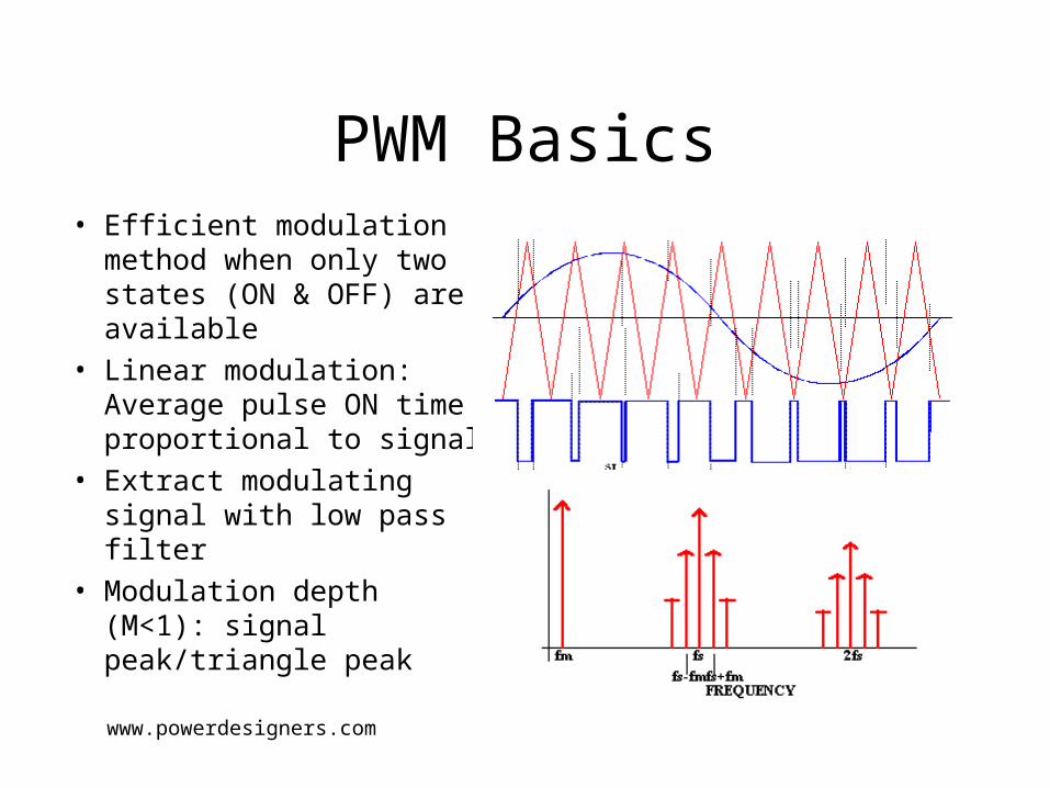
PWM Basics• Efficient modulation
method when only two states (ON & OFF) are available
• Linear modulation: Average pulse ON time proportional to signal
• Extract modulating signal with low pass filter
• Modulation depth (M<1): signal peak/triangle peakwww.powerdesigners.com
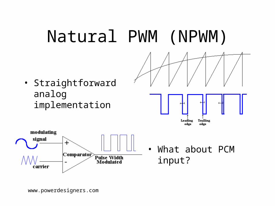
Natural PWM (NPWM)
• What about PCM input?
www.powerdesigners.com
• Straightforward analog implementation
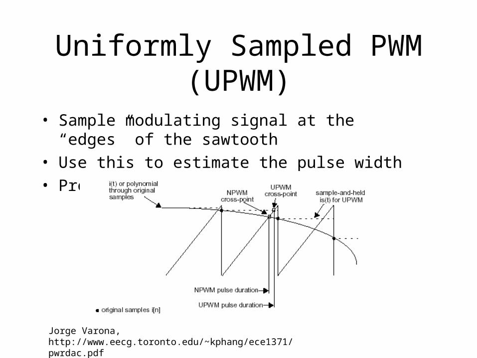
Uniformly Sampled PWM (UPWM)
Jorge Varona, http://www.eecg.toronto.edu/~kphang/ece1371/pwrdac.pdf
• Sample modulating signal at the “edges” of the sawtooth
• Use this to estimate the pulse width
• Problem: Introduces an error!
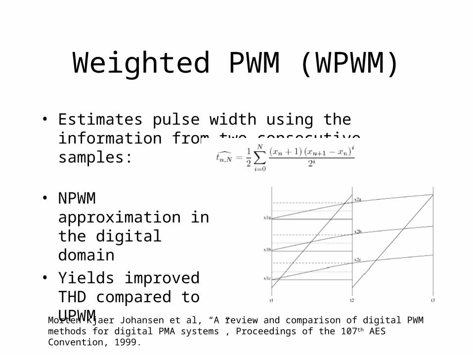
Weighted PWM (WPWM)
• Estimates pulse width using the information from two consecutive samples:
• NPWM approximation in the digital domain
• Yields improved THD compared to UPWM
Morten Kjaer Johansen et al, “A review and comparison of digital PWM methods for digital PMA systems”, Proceedings of the 107th AES Convention, 1999.
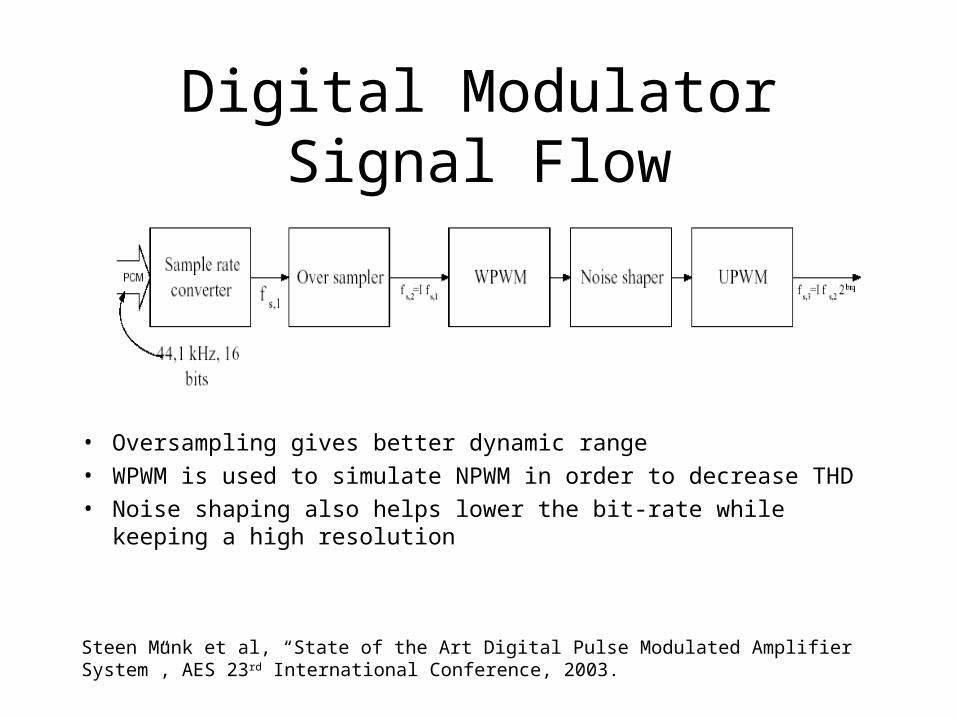
Digital Modulator Signal Flow
• Oversampling gives better dynamic range
• WPWM is used to simulate NPWM in order to decrease THD
• Noise shaping also helps lower the bit-rate while keeping a high resolution
Steen Munk et al, “State of the Art Digital Pulse Modulated Amplifier System”, AES 23 rd International Conference, 2003.
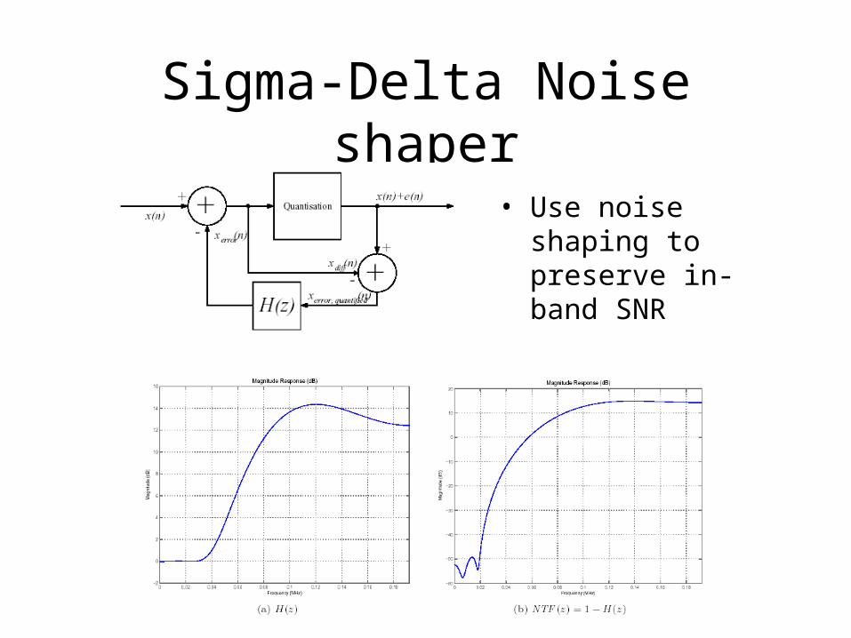
Sigma-Delta Noise shaper
• Use noise shaping to preserve in-band SNR
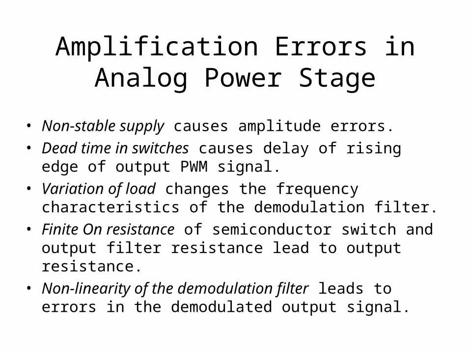
Amplification Errors in Analog Power Stage
• Non-stable supply causes amplitude errors.
• Dead time in switches causes delay of rising edge of output PWM signal.
• Variation of load changes the frequency characteristics of the demodulation filter.
• Finite On resistance of semiconductor switch and output filter resistance lead to output resistance.
• Non-linearity of the demodulation filter leads to errors in the demodulated output signal.
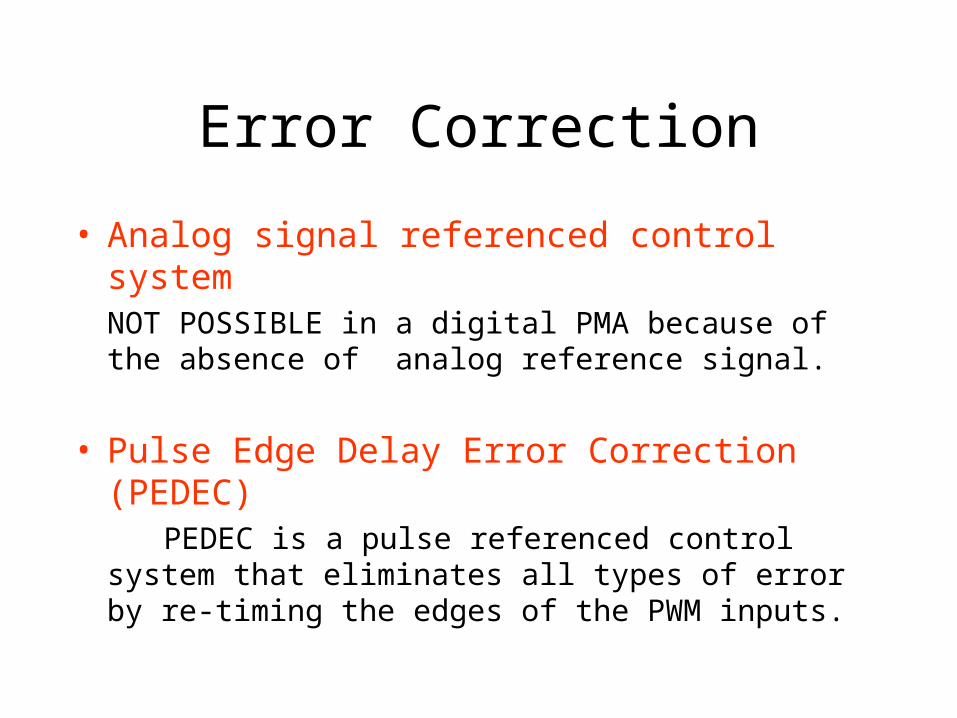
Error Correction
• Analog signal referenced control systemNOT POSSIBLE in a digital PMA because of the absence of analog reference signal.
• Pulse Edge Delay Error Correction (PEDEC) PEDEC is a pulse referenced control system that eliminates
all types of error by re-timing the edges of the PWM inputs.
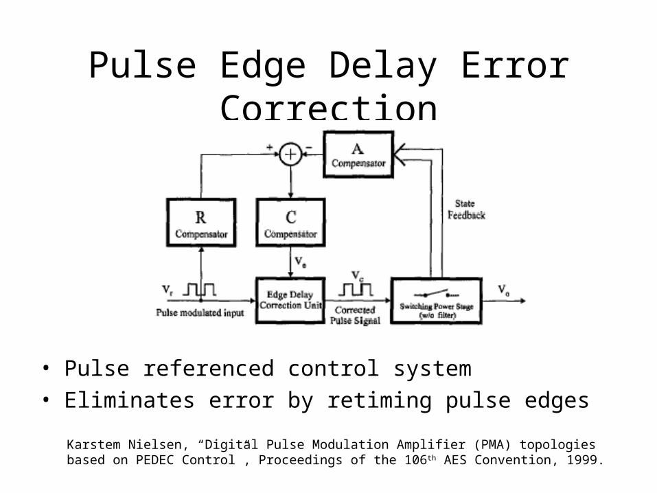
Pulse Edge Delay Error Correction
Karstem Nielsen, “Digital Pulse Modulation Amplifier (PMA) topologies based on PEDEC Control”, Proceedings of the 106th AES Convention, 1999.
• Pulse referenced control system
• Eliminates error by retiming pulse edges
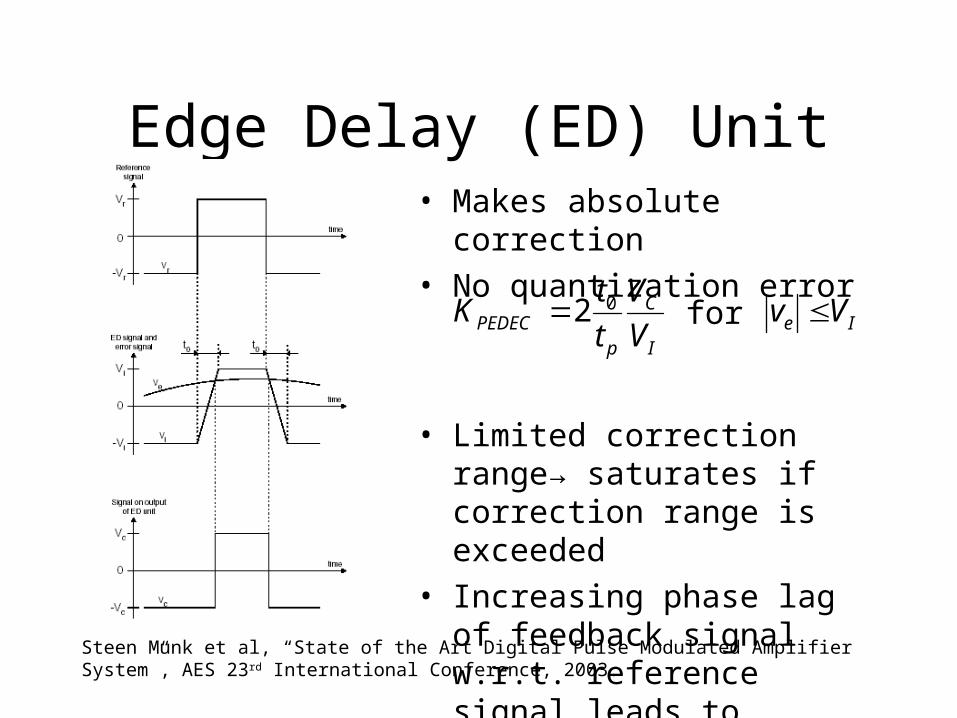
Edge Delay (ED) Unit
Steen Munk et al, “State of the Art Digital Pulse Modulated Amplifier System”, AES 23 rd International Conference, 2003.
I
C
pPEDEC V
V
t
tK 02 Ie Vv for
• Makes absolute correction
• No quantization error
• Limited correction range→ saturates if correction range is exceeded
• Increasing phase lag of feedback signal w.r.t. reference signal leads to saturation for very short or long pulses
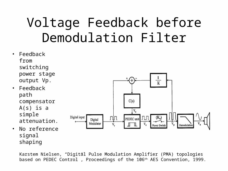
Voltage Feedback before Demodulation Filter
• Feedback from switching power stage output Vp.
• Feedback path compensator A(s) is a simple attenuation.
• No reference signal shaping
Karstem Nielsen, “Digital Pulse Modulation Amplifier (PMA) topologies based on PEDEC Control”, Proceedings of the 106th AES Convention, 1999.
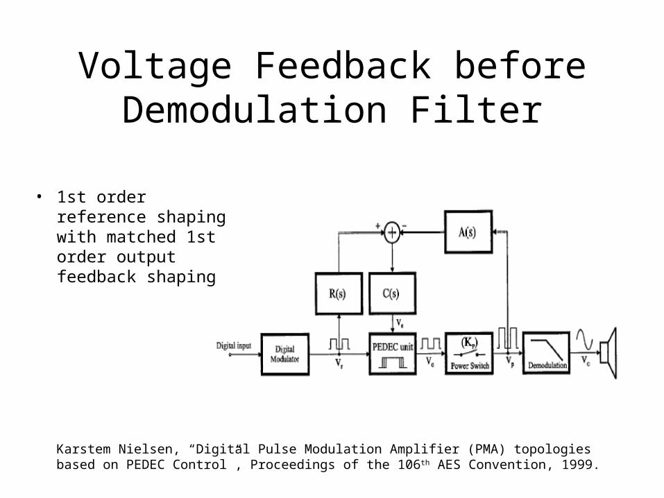
Voltage Feedback before Demodulation Filter
Karstem Nielsen, “Digital Pulse Modulation Amplifier (PMA) topologies based on PEDEC Control”, Proceedings of the 106th AES Convention, 1999.
• 1st order reference shaping with matched 1st order output feedback shaping
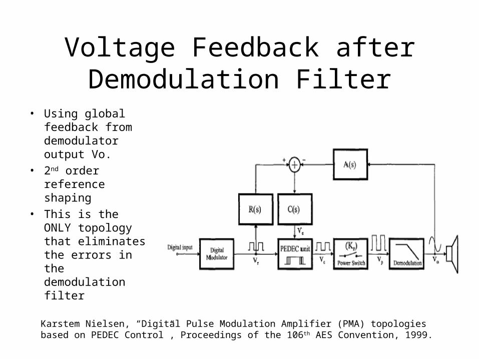
Voltage Feedback after Demodulation Filter
• Using global feedback from demodulator output Vo.
• 2nd order reference shaping
• This is the ONLY topology that eliminates the errors in the demodulation filter
Karstem Nielsen, “Digital Pulse Modulation Amplifier (PMA) topologies based on PEDEC Control”, Proceedings of the 106th AES Convention, 1999.
Volume Control
• A digital volume control is simple to implement but will decrease the dynamic range as the signal is attenuated.
• An analog volume control can retain the dynamic range, but it is not applicable to a digital PMA.
• GOAL: a volume control system that will not decrease dynamic range.
Intelligent Volume Control (IVC)
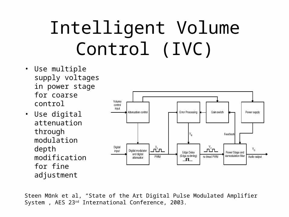
Intelligent Volume Control (IVC)
• Use multiple supply voltages in power stage for coarse control
• Use digital attenuation through modulation depth modification for fine adjustment
Steen Munk et al, “State of the Art Digital Pulse Modulated Amplifier System”, AES 23 rd International Conference, 2003.
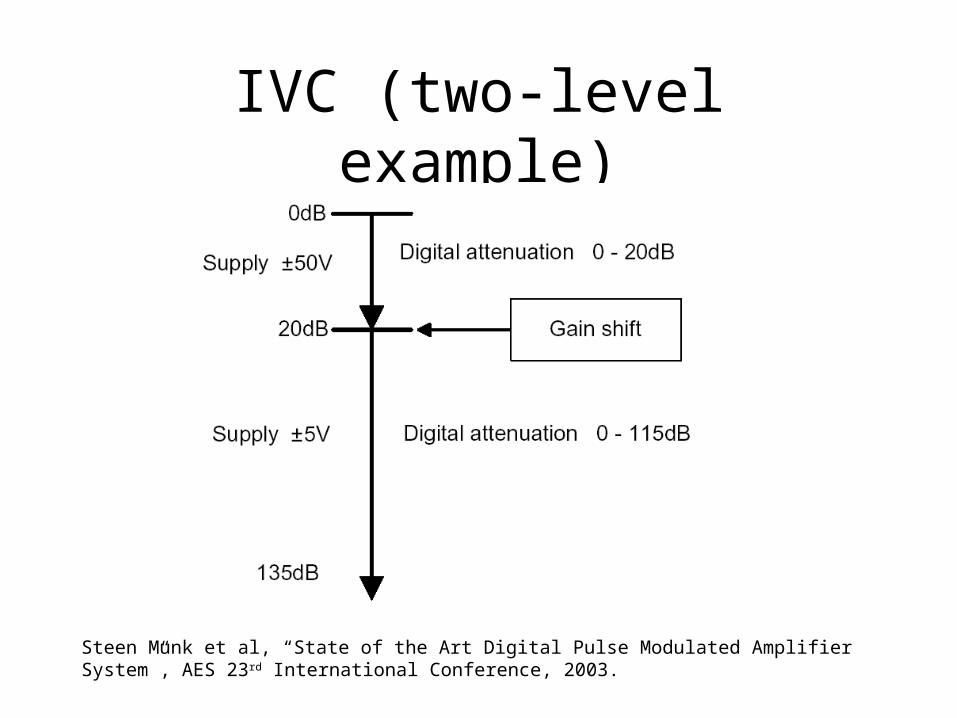
IVC (two-level example)
Steen Munk et al, “State of the Art Digital Pulse Modulated Amplifier System”, AES 23 rd International Conference, 2003.
IVC Advantages
• Improved dynamic range
• Improved edge related noise
• Improved efficiency
• Improved electromagnetic interference (EMI) characteristics
Summary
• Improve THD with WPWM
• Reduce noise by noise shaping
• Correct various errors through PEDEC
• Improve SNR of volume control by using multiple supply voltages


