Prior to use, please read this and relevant manuals thoroughly to fully understand the product.
MODEL ANS-Q-LARGE-U
MODELCODE
13J290
IB(NA)-0800495-E(1806)MEE
CONDITIONS OF USE FOR THE PRODUCT
(1) Mitsubishi programmable controller ("the PRODUCT") shall be used in conditions;i) where any problem, fault or failure occurring in the PRODUCT, if any, shall not lead to any major or serious accident; and ii) where the backup and fail-safe function are systematically or automatically provided outside of the PRODUCT for the case of any problem, fault or failure occurring in the PRODUCT.
(2) The PRODUCT has been designed and manufactured for the purpose of being used in general industries.MITSUBISHI SHALL HAVE NO RESPONSIBILITY OR LIABILITY (INCLUDING, BUT NOT LIMITED TO ANY AND ALL RESPONSIBILITY OR LIABILITY BASED ON CONTRACT, WARRANTY, TORT, PRODUCT LIABILITY) FOR ANY INJURY OR DEATH TO PERSONS OR LOSS OR DAMAGE TO PROPERTY CAUSED BY the PRODUCT THAT ARE OPERATED OR USED IN APPLICATION NOT INTENDED OR EXCLUDED BY INSTRUCTIONS, PRECAUTIONS, OR WARNING CONTAINED IN MITSUBISHI'S USER, INSTRUCTION AND/OR SAFETY MANUALS, TECHNICAL BULLETINS AND GUIDELINES FOR the PRODUCT.("Prohibited Application")Prohibited Applications include, but not limited to, the use of the PRODUCT in;
• Nuclear Power Plants and any other power plants operated by Power companies, and/or any other cases in which the public could be affected if any problem or fault occurs in the PRODUCT.
• Railway companies or Public service purposes, and/or any other cases in which establishment of a special quality assurance system is required by the Purchaser or End User.
• Aircraft or Aerospace, Medical applications, Train equipment, transport equipment such as Elevator and Escalator, Incineration and Fuel devices, Vehicles, Manned transportation, Equipment for Recreation and Amusement, and Safety devices, handling of Nuclear or Hazardous Materials or Chemicals, Mining and Drilling, and/or other applications where there is a significant risk of injury to the public or property.
A-1
Notwithstanding the above, restrictions Mitsubishi may in its sole discretion, authorize use of the PRODUCT in one or more of the Prohibited Applications, provided that the usage of the PRODUCT is limited only for the specific applications agreed to by Mitsubishi and provided further that no special quality assurance or fail-safe, redundant or other safety features which exceed the general specifications of the PRODUCTs are required. For details, please contact the Mitsubishi representative in your region.
A-2
REVISIONS*The manual number is given on the bottom right of the cover.
February 2013 IB(NA)-0800495-B Change of the external dimension diagram
November 2015 IB(NA)-0800495-C Descriptions regarding the Q series large type base unit are added.
December 2016 IB(NA)-0800495-D Descriptions are revised due to compliance with the new China RoHS.
June 2018 IB(NA)-0800495-E Descriptions are revised due to compliance with the Chinese standardized law.
This manual confers no industrial property rights or any rights of any other kind, nor does it confer any patent licenses. Mitsubishi Electric Corporation cannot be held responsible for any problems involving industrial property rights which may occur as a result of using the contents noted in this manual.
2. SYSTEM CONFIGURATION..........................................................................5
2.1 System Configuration............................................................................5
2.2 Precautions for System Configuration................................................. 10
2.3 Modules That Cannot be Mounted on the Q Series Large Type Base Unit (AnS Series Size) ............................................................... 11
3.1 Specifications of the Q Series Large Type Base Unit (AnS Series Size)................................................................................ 12
3.2 Specifications of the Q Series Large Type Blank Cover (AnS Series Size)................................................................................ 14
4. PARTS NAMES............................................................................................ 15
4.1 Parts Names ....................................................................................... 15
5. MOUNTING AND INSTALLATION............................................................... 18
5.2 Precautions for Installing the Q Series Large Type Base Unit (AnS Series Size)................................................................................ 19
5.3 Mounting and Installation of the Q Series Large Type Base Unit (AnS Series Size)................................................................................ 21
5.4 Mounting/Removing the Q Series Module .......................................... 23
6.1 Q Series Large Type Base Unit (AnS Series Size) ............................. 25
6.2 Q Series Large Type Blank Cover (AnS Series Size) ......................... 29
TERMS
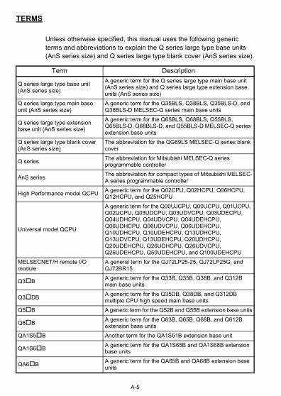
Unless otherwise specified, this manual uses the following generic terms and abbreviations to explain the Q series large type base units (AnS series size) and Q series large type blank cover (AnS series size).
Term Description
Q series large type base unit (AnS series size)
A generic term for the Q series large type main base unit (AnS series size) and Q series large type extension base units (AnS series size)
Q series large type main base unit (AnS series size)
A generic term for the Q35BLS, Q38BLS, Q35BLS-D, and Q38BLS-D MELSEC-Q series main base units
Q series large type extension base unit (AnS series size)
A generic term for the Q65BLS, Q68BLS, Q55BLS, Q65BLS-D, Q68BLS-D, and Q55BLS-D MELSEC-Q series extension base units
Q series large type blank cover (AnS series size)
The abbreviation for the QG69LS MELSEC-Q series blank cover
Q seriesThe abbreviation for Mitsubishi MELSEC-Q series programmable controller
AnS seriesThe abbreviation for compact types of Mitsubishi MELSEC-A series programmable controller
High Performance model QCPUA generic term for the Q02CPU, Q02HCPU, Q06HCPU, Q12HCPU, and Q25HCPU
Universal model QCPU
A generic term for the Q00UJCPU, Q00UCPU, Q01UCPU, Q02UCPU, Q03UDCPU, Q03UDVCPU, Q03UDECPU, Q04UDHCPU, Q04UDVCPU, Q04UDEHCPU, Q06UDHCPU, Q06UDVCPU, Q06UDEHCPU, Q10UDHCPU, Q10UDEHCPU, Q13UDHCPU, Q13UDVCPU, Q13UDEHCPU, Q20UDHCPU, Q20UDEHCPU, Q26UDHCPU, Q26UDVCPU, Q26UDEHCPU, Q50UDEHCPU, and Q100UDEHCPU
MELSECNET/H remote I/O module
A general term for the QJ72LP25-25, QJ72LP25G, and QJ72BR15
Q3BA generic term for the Q33B, Q35B, Q38B, and Q312B main base units
Q3DBA generic term for the Q35DB, Q38DB, and Q312DB multiple CPU high speed main base units
Q5B A generic term for the Q52B and Q55B extension base units
Q6BA generic term for the Q63B, Q65B, Q68B, and Q612B extension base units
QA1S5B Another term for the QA1S51B extension base unit
QA1S6BA generic term for the QA1S65B and QA1S68B extension base units
QA6BA generic term for the QA65B and QA68B extension base units
A-5
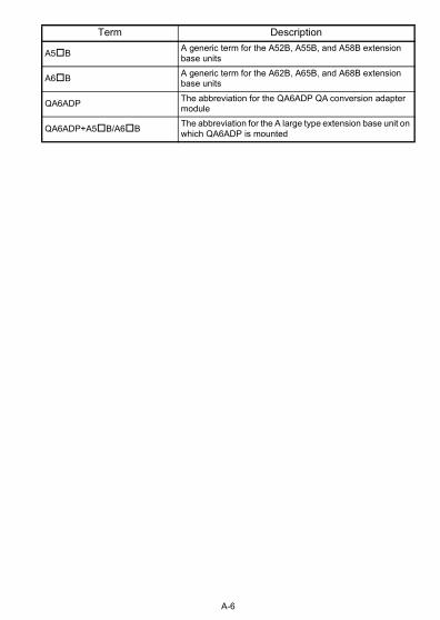
A5BA generic term for the A52B, A55B, and A58B extension base units
A6BA generic term for the A62B, A65B, and A68B extension base units
QA6ADPThe abbreviation for the QA6ADP QA conversion adapter module
QA6ADP+A5B/A6BThe abbreviation for the A large type extension base unit on which QA6ADP is mounted
Term Description
A-6
1. OVERVIEW
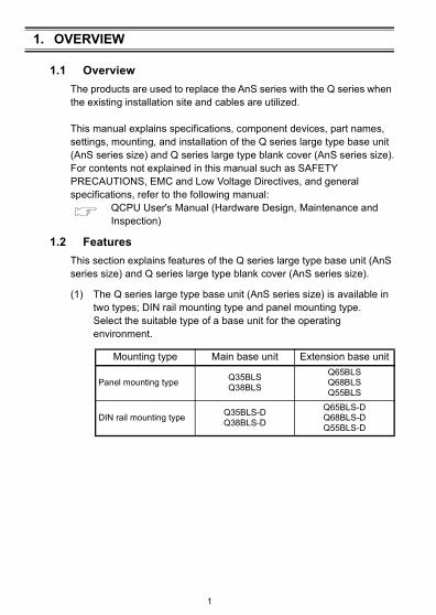
1.1 Overview
The products are used to replace the AnS series with the Q series when the existing installation site and cables are utilized.
This manual explains specifications, component devices, part names, settings, mounting, and installation of the Q series large type base unit (AnS series size) and Q series large type blank cover (AnS series size).For contents not explained in this manual such as SAFETY PRECAUTIONS, EMC and Low Voltage Directives, and general specifications, refer to the following manual:
QCPU User's Manual (Hardware Design, Maintenance and Inspection)
1.2 Features
This section explains features of the Q series large type base unit (AnS series size) and Q series large type blank cover (AnS series size).
(1) The Q series large type base unit (AnS series size) is available in two types; DIN rail mounting type and panel mounting type.Select the suitable type of a base unit for the operating environment.
Mounting type Main base unit Extension base unit
Panel mounting typeQ35BLSQ38BLS
Q65BLSQ68BLSQ55BLS
DIN rail mounting typeQ35BLS-DQ38BLS-D
Q65BLS-DQ68BLS-DQ55BLS-D
1
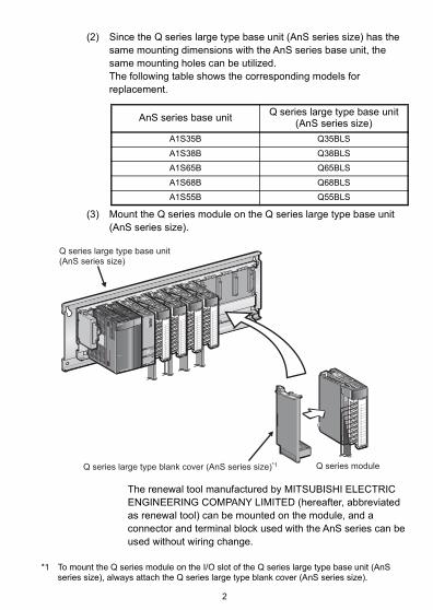
(2) Since the Q series large type base unit (AnS series size) has the same mounting dimensions with the AnS series base unit, the same mounting holes can be utilized.The following table shows the corresponding models for replacement.
(3) Mount the Q series module on the Q series large type base unit (AnS series size).
The renewal tool manufactured by MITSUBISHI ELECTRIC ENGINEERING COMPANY LIMITED (hereafter, abbreviated as renewal tool) can be mounted on the module, and a connector and terminal block used with the AnS series can be used without wiring change.
*1 To mount the Q series module on the I/O slot of the Q series large type base unit (AnS series size), always attach the Q series large type blank cover (AnS series size).
AnS series base unitQ series large type base unit
(AnS series size)
A1S35B Q35BLS
A1S38B Q38BLS
A1S65B Q65BLS
A1S68B Q68BLS
A1S55B Q55BLS
24VDC
4mA
QX40
+-
24VDC
4mA
QX40
+-
24VDC
4mA
QX40
+-
24VDC
4mA
QX40
+-
Q12HCPU
MODE
RUN
ERR.
USER
BAT.
BOOT
PULL
USB
RS-232
MELSEC
Q62P
POWER
PULL
24VDC
4mA
QX40
+-
Q series module
Q series large type base unit (AnS series size)
Q series large type blank cover (AnS series size)*1
2
1.3 Supplied Parts
(1) Q series large type main base unit (AnS series size) (panel mounting type)
*1 The Q series large type extension base unit (AnS series size) does not include with the guidelines.
(2) Q series large type main base unit (AnS series size)(DIN rail mounting type)
Product Model Quantity Remarks
Q series large type main base unit (AnS series size)
Q35BLS
1 -
Q38BLS
Q65BLS
Q68BLS
Q55BLS
Base unit mounting screw - 4 M5 × 25 screw
This manual IB-0800495 1 -
Safety Guidelines*1 IB-0800423 1 -
Product Model Quantity Remarks
Q series large type main base unit (AnS series size)
Fixing bracket for terminal block conversion adapter
- 1 -
Bracket fixing screw - 6 M4×8 screw
3
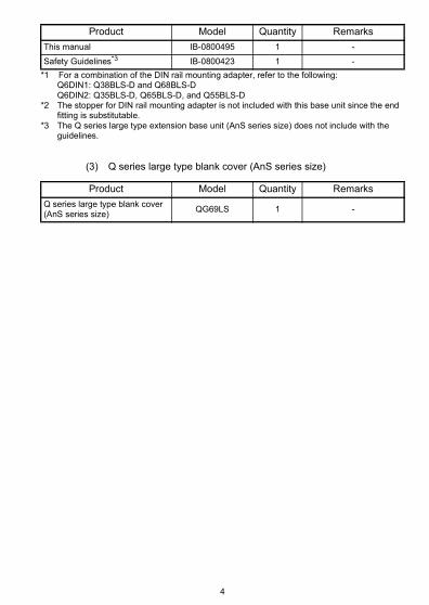
*1 For a combination of the DIN rail mounting adapter, refer to the following:Q6DIN1: Q38BLS-D and Q68BLS-DQ6DIN2: Q35BLS-D, Q65BLS-D, and Q55BLS-D
*2 The stopper for DIN rail mounting adapter is not included with this base unit since the end fitting is substitutable.
*3 The Q series large type extension base unit (AnS series size) does not include with the guidelines.
(3) Q series large type blank cover (AnS series size)
This manual IB-0800495 1 -
Safety Guidelines*3 IB-0800423 1 -
Product Model Quantity Remarks
Q series large type blank cover (AnS series size)
QG69LS 1 -
Product Model Quantity Remarks
4
2. SYSTEM CONFIGURATION
2.1 System Configuration
This section explains system configuration when using the Q serieslarge type base unit (AnS series size). The following modules can be mounted on the CPU slot of the Q series large type base unit (AnS series size).
• High Performance model QCPU • Universal model QCPU (except Q00UJCPU) • MELSECNET/H remote I/O module
(1) System configuration using the High Performance model QCPU and Universal model QCPU
CPU 0 1 2 3 4 5 6 7
Power supply module
CPU module
Q series large type main base unit (AnS series size) (Q3�BLS, Q3�BLS-D), Q series main base unit (Q3�B, Q3�DB), or Q series large type main base unit (Q3�BL)
Q series extension base unit (Q5�B, Q6�B), Q series large type extension base unit (AnS series size) (Q6�BLS, Q6�BLS-D, Q55BLS, Q55BLS-D), or Q series large type extension base unit (Q6�BL, Q55BL)
Q series extension base unit on which AnS series module can be mounted (QA1S5�B, QA1S6�B)
Q series extension base unit on which A series module can be mounted (QA6�B)
QA conversion adapter + A/QnA series extension base unit (QA6ADP + A5�B/A6�B)
Main base unit
Extension base unit
Slot number
8 9 10 11 12 13 14 15
16 17 18 19 20 21 22 23
24 25 26 27 28 29 30 31
32 33 34 35 36 37 38 39
5
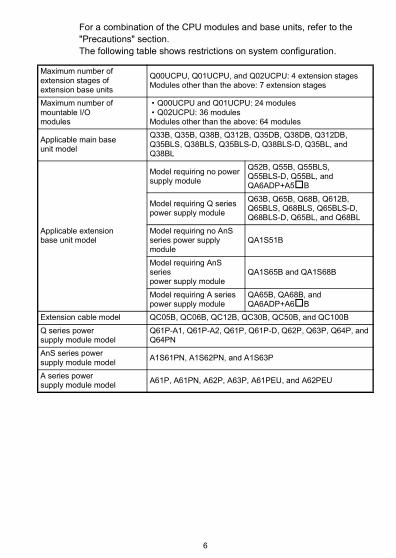
For a combination of the CPU modules and base units, refer to the"Precautions" section.The following table shows restrictions on system configuration.
Maximum number ofextension stages ofextension base units
Q00UCPU, Q01UCPU, and Q02UCPU: 4 extension stagesModules other than the above: 7 extension stages
Maximum number ofmountable I/Omodules
• Q00UCPU and Q01UCPU: 24 modules• Q02UCPU: 36 modulesModules other than the above: 64 modules
Extension cable model QC05B, QC06B, QC12B, QC30B, QC50B, and QC100B
Q series powersupply module model
Q61P-A1, Q61P-A2, Q61P, Q61P-D, Q62P, Q63P, Q64P, and Q64PN
AnS series powersupply module model
A1S61PN, A1S62PN, and A1S63P
A series powersupply module model
A61P, A61PN, A62P, A63P, A61PEU, and A62PEU
6
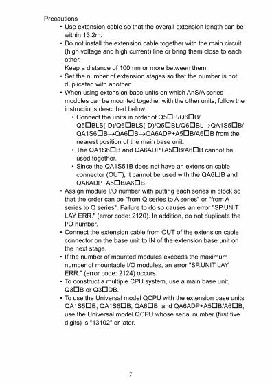
Precautions • Use extension cable so that the overall extension length can be
within 13.2m. • Do not install the extension cable together with the main circuit
(high voltage and high current) line or bring them close to each other.Keep a distance of 100mm or more between them.
• Set the number of extension stages so that the number is not duplicated with another.
• When using extension base units on which AnS/A seriesmodules can be mounted together with the other units, follow the instructions described below.
• Connect the units in order of Q5B/Q6B/Q5BLS(-D)/Q6BLS(-D)/Q5BL/Q6BLQA1S5B/ QA1S6BQA6BQA6ADP+A5B/A6B from the nearest position of the main base unit.
• The QA1S6B and QA6ADP+A5B/A6B cannot be used together.
• Since the QA1S51B does not have an extension cable connector (OUT), it cannot be used with the QA6B and QA6ADP+A5B/A6B.
• Assign module I/O number with putting each series in block so that the order can be "from Q series to A series" or "from A series to Q series". Failure to do so causes an error "SP.UNIT LAY ERR." (error code: 2120). In addition, do not duplicate the I/O number.
• Connect the extension cable from OUT of the extension cable connector on the base unit to IN of the extension base unit on the next stage.
• If the number of mounted modules exceeds the maximum number of mountable I/O modules, an error "SP.UNIT LAY ERR." (error code: 2124) occurs.
• To construct a multiple CPU system, use a main base unit, Q3B or Q3DB.
• To use the Universal model QCPU with the extension base units QA1S5B, QA1S6B, QA6B, and QA6ADP+A5B/A6B, use the Universal model QCPU whose serial number (first five digits) is "13102" or later.
7
(2) System configuration using the MELSECNET/H remote I/O module
Q series large type extension base unit (AnS series size) (Q6�BLS, Q6�BLS-D, Q55BLS, Q55BLS-D), Q series extension base unit (Q5�B, Q6�B), or Q series large type extension base unit (Q6�BL, Q55BL)
Q series extension base unit (Q5�B, Q6�B), Q series large type extension base unit (AnS series size) (Q6�BLS, Q6�BLS-D, Q55BLS, Q55BLS-D), or Q series large type extension base unit (Q6�BL, Q55BL)
Main base unit
Extension base unit
Slot number
Q series large type main base unit (AnS series size) (Q3�BLS, Q3�BLS-D), Q series main base unit (Q3�B, Q3�DB), or Q series large type main base unit (Q3�BL)
Q series extension base unit (Q5�B, Q6�B), Q series large type extension base unit (AnS series size) (Q6�BLS, Q6�BLS-D, Q55BLS, Q55BLS-D), or Q series large type extension base unit (Q6�BL, Q55BL)
Power supply module
MELSECNET/H remote I/O module
CPU 0 1 2 3 4 5 6 7
8 9 10 11 12 13 14 15
16 17 18 19 20 21 22 23
24 25 26 27 28 29 30 31
8
The following table shows restrictions on system configuration.
Precautions • Use extension cable so that the overall extension length can be
within 13.2m. • Do not install the extension cable together with the main circuit
(high voltage and high current) line or bring them close to each other.
• Keep a distance of 100mm or more between them. • Set the number of extension stages so that the number is not
duplicated with another. • Connect the extension cable from OUT of the extension cable
connector on the base unit to IN of the extension base unit on the next stage.
• If the number of mounted modules exceeds the maximum number of mountable I/O modules, an error "SP.UNIT LAY ERR." (error code: 2124) occurs.
Maximum number ofextension stages ofextension base units
7 extension stages
Maximum number ofmountable I/O modules
64 modules
Applicable main baseunit model
Q33B, Q35B, Q38B, Q35BLS, Q38BLS, Q35BLS-D, Q38BLS-D, Q35BL, and Q38BL
Extension cable model QC05B, QC06B, QC12B, QC30B, QC50B, and QC100B
Q series power supplymodule model
Q61P-A1, Q61P-A2, Q61P, Q61P-D, Q62P, Q63P, Q64P, and Q64PN
9
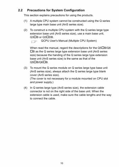
2.2 Precautions for System Configuration
This section explains precautions for using the products.
(1) A multiple CPU system cannot be constructed using the Q series large type main base unit (AnS series size).
(2) To construct a multiple CPU system with the Q series large type extension base unit (AnS series size), use a main base unit, Q3B or Q3DB.
QCPU User's Manual (Multiple CPU System)
When read the manual, regard the descriptions for the Q5B/Q6 B as the Q series large type extension base unit (AnS series size) because the handing of the Q series large type extension base unit (AnS series size) is the same as that of the Q5B/Q6B.
(3) To mount the Q series module on Q series large type base unit (AnS series size), always attach the Q series large type blank cover (AnS series size).(The cover is not necessary for a module mounted on CPU slot and power supply.)
(4) In Q series large type (AnS series size), the extension cable connector is not on the right side of the base unit. When the extension cable is used, make sure the cable lengths and the way to connect the cable.
10
2.3 Modules That Cannot be Mounted on the Q Series Large Type Base Unit (AnS Series Size)
This section explains modules that cannot be mounted on the Q series large type base unit (AnS series size).
(1) Two-slot module
(2) Module on which the Q series large type blank cover (AnS series size) cannot be attached • Module whose height exceeds 98mm • Module with a bracket on its top • Module having a projection (such as a connector) on its bottom • Module on which the Q7BAT-SET has been mounted
Ex. Q66AD-DG, Q66DA-G, Q68AD-G, Q68RD3-G, Q68TD-G-H02, Q64AD2DA, QD75M1, QD75MH1, QD75M2, QD75MH2, QD75M4, QD75MH4, and the QJ71WS96 on which the Q7BAT-SET has been mounted
A module with a bracket cannot be mounted.
A module with the height exceeding 98mm cannot be mounted.
A two-slot module cannot be mounted.
A module having a projection (such as a connector) on its bottom cannot be mounted.
11
3. SPECIFICATIONS
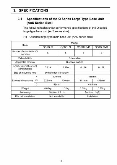
3.1 Specifications of the Q Series Large Type Base Unit (AnS Series Size)
The following tables show performance specifications of the Q series large type base unit (AnS series size).
(1) Q series large type main base unit (AnS series size)
ItemModel
Q35BLS Q38BLS Q35BLS-D Q38BLS-D
Number of mountable I/O modules
5 8 5 8
Extendability Extendable
Applicable module Q series module
5 VDC internal current consumption
0.11A 0.12A 0.11A 0.12A
Size of mounting hole 6 hole (for M5 screw) -
External dimensions
H 130mm 118mm
W 325mm 430mm 311mm 416mm
D 53mm 48.5mm
Weight 0.82kg 1.32kg 0.59kg 0.72kg
Accessory Section 1.3 (1) Section 1.3 (2)
DIN rail installation Not installable Installable
12
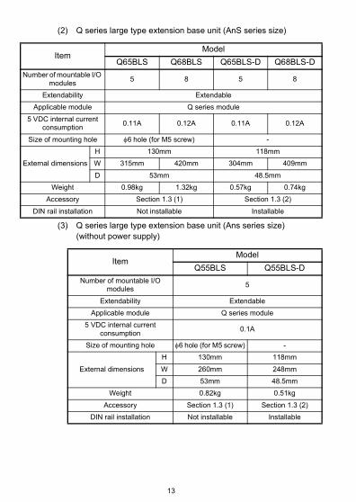
(2) Q series large type extension base unit (AnS series size)
(3) Q series large type extension base unit (Ans series size) (without power supply)
ItemModel
Q65BLS Q68BLS Q65BLS-D Q68BLS-D
Number of mountable I/O modules
5 8 5 8
Extendability Extendable
Applicable module Q series module
5 VDC internal current consumption
0.11A 0.12A 0.11A 0.12A
Size of mounting hole 6hole (for M5 screw) -
External dimensions
H 130mm 118mm
W 315mm 420mm 304mm 409mm
D 53mm 48.5mm
Weight 0.98kg 1.32kg 0.57kg 0.74kg
Accessory Section 1.3 (1) Section 1.3 (2)
DIN rail installation Not installable Installable
ItemModel
Q55BLS Q55BLS-D
Number of mountable I/O modules
5
Extendability Extendable
Applicable module Q series module
5 VDC internal current consumption
0.1A
Size of mounting hole 6hole (for M5 screw) -
External dimensions
H 130mm 118mm
W 260mm 248mm
D 53mm 48.5mm
Weight 0.82kg 0.51kg
Accessory Section 1.3 (1) Section 1.3 (2)
DIN rail installation Not installable Installable
13
3.2 Specifications of the Q Series Large Type Blank Cover (AnS Series Size)
The following tables show performance specifications of the Q series large type blank cover (AnS series size).
ItemModel
QG69LS
External dimensions
H 108mm
W 34.5mm
D 54mm
Weight 0.03kg
14
4. PARTS NAMES
4.1 Parts Names
This section explains the part names of the Q series large type base unit (AnS series size) and Q series large type blank cover (AnS series size).
(1) Q series large type base unit (AnS series size)(panel mounting type)
No. Name Description
1) Extension cable connectorConnector for connecting an extension cable (for signal communications with the extension base unit)
2) Base cover Protective cover of extension cable connector
3) Module connectorConnector for mounting power supply module, CPU module, Q series large type I/O module, and MELSEC-Q series module
4) Module fixing screw holeScrew hole for fixing a module to the base unit(screw size: M3×12)
5) Base mounting holeHole for installing the base unit on a panel such as control panel (for M5 screw)
6)Terminal block conversion adapter fixing hole
Screw hole for fixing a terminal block conversion adapter (screw size: M3×8)
2)
5)
6)
1) 4)
3)
15
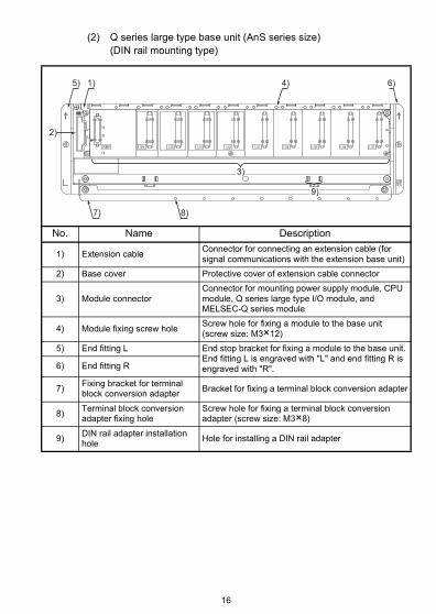
(2) Q series large type base unit (AnS series size)(DIN rail mounting type)
No. Name Description
1) Extension cableConnector for connecting an extension cable (for signal communications with the extension base unit)
2) Base cover Protective cover of extension cable connector
3) Module connectorConnector for mounting power supply module, CPU module, Q series large type I/O module, and MELSEC-Q series module
4) Module fixing screw holeScrew hole for fixing a module to the base unit(screw size: M3×12)
5) End fitting L End stop bracket for fixing a module to the base unit. End fitting L is engraved with "L" and end fitting R is engraved with "R".6) End fitting R
7)Fixing bracket for terminal block conversion adapter
Bracket for fixing a terminal block conversion adapter
8)Terminal block conversion adapter fixing hole
Screw hole for fixing a terminal block conversion adapter (screw size: M3×8)
9)DIN rail adapter installation hole
Hole for installing a DIN rail adapter
2)
5)
7) 8)
3)
1) 4) 6)
9)
16
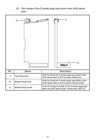
(3) Part names of the Q series large type blank cover (AnS series size)
No. Name Description
1) Top fixing hookHook for fixing the Q series large type blank cover (AnS series size) to the Q series module top
2) Bottom fixing hookHook for fixing the Q series large type blank cover (AnS series size) to the Q series module bottom
3) Module fixing screw Screw for fixing a module to the Q series large type base unit (AnS series size). (screw size: M3×12)
3) 1)
2)
17
5. MOUNTING AND INSTALLATION
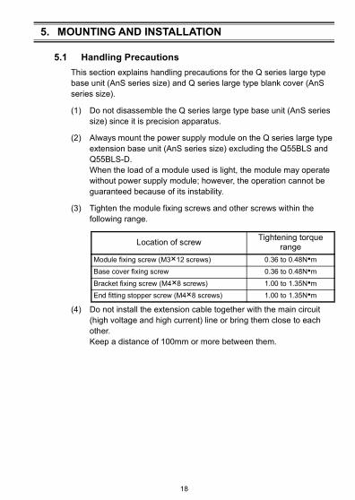
5.1 Handling Precautions
This section explains handling precautions for the Q series large type base unit (AnS series size) and Q series large type blank cover (AnS series size).
(1) Do not disassemble the Q series large type base unit (AnS series size) since it is precision apparatus.
(2) Always mount the power supply module on the Q series large type extension base unit (AnS series size) excluding the Q55BLS and Q55BLS-D.When the load of a module used is light, the module may operate without power supply module; however, the operation cannot be guaranteed because of its instability.
(3) Tighten the module fixing screws and other screws within the following range.
(4) Do not install the extension cable together with the main circuit (high voltage and high current) line or bring them close to each other.Keep a distance of 100mm or more between them.
Location of screwTightening torque
range
Module fixing screw (M3×12 screws) 0.36 to 0.48N•m
Base cover fixing screw 0.36 to 0.48N•m
Bracket fixing screw (M4×8 screws) 1.00 to 1.35N•m
End fitting stopper screw (M4×8 screws) 1.00 to 1.35N•m
18
5.2 Precautions for Installing the Q Series Large Type Base Unit (AnS Series Size)
(1) Module installation positionProvide the following distances between the top and bottom of the module and other structure or components to ensure ventilation for heat dissipation and to change the module easily.
*1 30mm or more is required when writing duct is 50mm or less in height. Otherwise, at least 40mm is required.
*2 20mm or more is required when the extension cable is connected without removing adjacent modules.
*3 80mm or more is required when the connector type is used. For Q8BAT, 80mm or more is required when the connection cable for Q8BAT is used.
*4 For Q7BAT, 45mm or more is required.*5 For Q8BAT, 30mm or more is required from both top and bottom sides of the module.*6 For Q8BAT, 5mm or more is required from both left and right sides of the module.
(2) Module installation direction
(a) Install the programmable controller in the direction shown below to ensure ventilation for heat dissipation.
Indicates the control panel top, wiring duct, or any part position.
5mm or more *2, *6 5mm or more *6
30mm or more *4, *5
Control panel
30mm or more *1, *5
*5, *6
*4
Programmable controller
20mm or more *3
Door
19
(b) Do not install it in the directions shown below.
(3) Install the base unit on a flat surface.When the base unit is installed on an uneven surface, the printed-circuit board may be strained, resulting in a malfunction.
(4) Do not install the programmable controller together with a vibration source such as a large electromagnetic contactor or non-fuse breaker. Install the programmable controller to the separate panel or isolate it as far as possible.
(5) Provide the following distances between the programmable controller and devices (contactor and relay) to avoid the influence of radiated noise or heat. • Device installed in front of the programmable controller: 100mm
or more • Device installed on either side of the programmable controller:
50mm or more
Vertical mounting Horizontal installation
At least 50mm
At least 50mm
Contactor, relay, etc.
At least 100mm
20
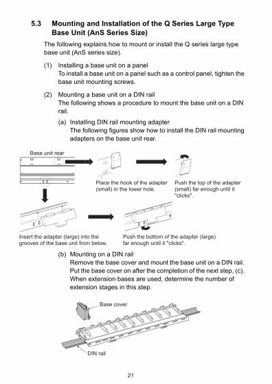
5.3 Mounting and Installation of the Q Series Large Type Base Unit (AnS Series Size)
The following explains how to mount or install the Q series large type base unit (AnS series size).
(1) Installing a base unit on a panelTo install a base unit on a panel such as a control panel, tighten the base unit mounting screws.
(2) Mounting a base unit on a DIN railThe following shows a procedure to mount the base unit on a DIN rail.
(a) Installing DIN rail mounting adapterThe following figures show how to install the DIN rail mounting adapters on the base unit rear.
(b) Mounting on a DIN railRemove the base cover and mount the base unit on a DIN rail. Put the base cover on after the completion of the next step, (c). When extension bases are used, determine the number of extension stages in this step.
Base unit rear
Insert the adapter (large) into the grooves of the base unit from below.
Push the bottom of the adapter (large) far enough until it "clicks".
Place the hook of the adapter (small) in the lower hole.
Push the top of the adapter (small) far enough until it "clicks".
Base cover
DIN rail
21
(c) Attaching the end fittingAttach the end fitting L and R on the both ends of a DIN rail. Slide them to the position of the end fitting mounting holes on the base unit. Loosen the stopper screws and hitch the hooks of the stopper to the DIN rail.Tighten the bracket fixing screws on each corner to firmly lock the end fitting in place.
(d) Fixing bracket for terminal block conversion adapter installationHook the fixing bracket for terminal block conversion adapter to the bottom side of a DIN rail. Place the bracket to the mounting hole for the end fitting L and R, then tighten the bracket fixing screws on each side to fix the bracket.
M4 8 screw
M4 8 screw
Stopper screw
End fitting L
Stopper screw
End fitting R
End fittingStopper
Stopper screw
DIN rail
Hitch both hooks of the stopper to the DIN rail. Tilt the stopper slightly downward if the hook does not come out from the stopper.
M4 8 screw
Fixing bracket for terminal block conversion adapter
M4 8 screw
22
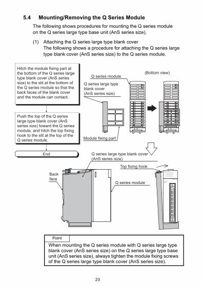
5.4 Mounting/Removing the Q Series Module
The following shows procedures for mounting the Q series moduleon the Q series large type base unit (AnS series size).
(1) Attaching the Q series large type blank cover The following shows a procedure for attaching the Q series large type blank cover (AnS series size) to the Q series module.
Point
When mounting the Q series module with Q series large type blank cover (AnS series size) on the Q series large type base unit (AnS series size), always tighten the module fixing screws of the Q series large type blank cover (AnS series size).
Q series large type blank cover (AnS series size)
Back face
Q series module
Module fixing part
Q series large type blank cover (AnS series size)
Top fixing hook
Q series module(Bottom view)
Hitch the module fixing part at the bottom of the Q series large type blank cover (AnS series size) to the slit at the bottom of the Q series module so that the back faces of the blank cover and the module can contact.
Push the top of the Q series large type blank cover (AnS series size) toward the Q series module, and hitch the top fixing hook to the slit at the top of the Q series module.
End
23
(2) Removing the Q series large type blank cover (AnS series size)To remove the Q series large type blank cover (AnS series size) from the Q series module, remove the bottom fixing hook first.
(3) Mounting to/removal from the Q series large type base unitFor procedures of mounting/removing the Q series module on/from the Q series large type base unit, refer to the following manual.
QCPU User's Manual (Hardware Design, Maintenance and Inspection)
24
6. EXTERNAL DIMENSIONS
The following shows external dimensions diagrams of the Q series large type base unit (AnS series size) and Q series large type blank cover (AnS series size).
6.1 Q Series Large Type Base Unit (AnS Series Size)
(1) Q35BLS
(2) Q35BLS-D
4-Mounting screw
(M5 25)
Unit: mm
53
11
0
13
0
305
325
Unit: mm
48.5
11
8
311
25
(3) Q38BLS
(4) Q38BLS-D
(5) Q65BLS
Unit: mm
4-Mounting screw
(M5 25)
53 430
11
0
13
0
410
Unit: mm
48.5
11
8
416
Unit: mm
4-Mounting screw
(M5 25)
53
11
0
13
0
295
315
26
(6) Q65BLS-D
(7) Q68BLS
(8) Q68BLS-D
Unit: mm
48.5
11
8
304
Unit: mm
4-Mounting screw
(M5 25)
53
11
0
13
0
400
420
Unit: mm
48.5
11
8
409
27
(9) Q55BLS
(10) Q55BLS-D
Unit: mm
4-Mounting screw
(M5 25)
53
11
0
13
0
260
240
Unit: mm
11
8
24848.5
28
6.2 Q Series Large Type Blank Cover (AnS Series Size)
(1) QG69LS
34.5
Unit: mm
54
10
8
(1.8)
(1.8)
29
WARRANTYMitsubishi will not be held liable for damage caused by factors found not to be the cause of Mitsubishi; machine damage or lost profits caused by faults in the Mitsubishi products; damage, secondary damage, accident compensation caused by special factors unpredictable by Mitsubishi; damages to products other than Mitsubishi products; and to other duties.
Specifications subject to change without notice.
HEAD OFFICE : TOKYO BUILDING, 2-7-3 MARUNOUCHI, CHIYODA-KU, TOKYO 100-8310, JAPANNAGOYA WORKS : 1-14, YADA-MINAMI 5-CHOME, HIGASHI-KU, NAGOYA, JAPAN
When exported from Japan, this manual does not require application to the Ministry of Economy, Trade and Industry for service transaction permission.
MITSUBISHI ELECTRIC TURKEY A.Ş Ümraniye Branch Serifali Mahallesi Nutuk Sokak No:5, TR-34775 Umraniye/Istanbul, TurkeyTel : +90-216-526-3990MITSUBISHI ELECTRIC EUROPE B.V. Dubai Branch Dubai Silicon Oasis, P.O.BOX 341241, Dubai, U.A.E.Tel : +971-4-3724716ADROIT TECHNOLOGIES 20 Waterford Office Park, 189 Witkoppen Road, Fourways, South AfricaTel : +27-11-658-8100
MITSUBISHI ELECTRIC AUTOMATION (CHINA) LTD. No.1386 Hongqiao Road, Mitsubishi Electric Automation Center, Shanghai, ChinaTel : +86-21-2322-3030SETSUYO ENTERPRISE CO., LTD. 6F, No.105, Wugong 3rd Road, Wugu District, New Taipei City 24889, TaiwanTel : +886-2-2299-2499MITSUBISHI ELECTRIC AUTOMATION KOREA CO., LTD. 7F-9F, Gangseo Hangang Xi-tower A, 401, Yangcheon-ro, Gangseo-Gu, Seoul 07528, KoreaTel : +82-2-3660-9530MITSUBISHI ELECTRIC ASIA PTE. LTD. 307, Alexandra Road, Mitsubishi Electric Building, Singapore 159943Tel : +65-6473-2308
MITSUBISHI ELECTRIC FACTORY AUTOMATION (THAILAND) CO., LTD. 12th Floor, SV.City Building, Office Tower 1, No. 896/19 and 20 Rama 3 Road, Kwaeng Bangpongpang, Khet Yannawa, Bangkok 10120, ThailandTel : +66-2682-6522MITSUBISHI ELECTRIC VIETNAM COMPANY LIMITED Hanoi Branch 6th Floor, Detech Tower, 8 Ton That Thuyet Street, My Dinh 2 Ward, Nam Tu Liem District, Hanoi, VietnamTel : +84-4-3937-8075PT. MITSUBISHI ELECTRIC INDONESIAGedung Jaya 11th Floor, JL. MH. Thamrin No.12, Jakarta Pusat 10340, IndonesiaTel : +62-21-3192-6461
MITSUBISHI ELECTRIC INDIA PVT. LTD. Pune Branch Emerald House, EL-3, J Block, M.I.D.C., Bhosari, Pune-411026, Maharashtra, IndiaTel : +91-20-2710-2000
USA MITSUBISHI ELECTRIC AUTOMATION, INC. 500 Corporate Woods Parkway, Vernon Hills, IL 60061, U.S.A.Tel : +1-847-478-2100
Turkey
Sales office/Tel
Country/Region
Sales office/Tel
Country/Region
Mexico MITSUBISHI ELECTRIC AUTOMATION, INC. Mexico Branch Mariano Escobedo #69, Col. Zona Industrial, Tlalnepantla Edo. Mexico, C.P.54030Tel : +52-55-3067-7500
UAE
Brazil MITSUBISHI ELECTRIC DO BRASIL COMÉRCIO E SERVIÇOS LTDA. Avenida Adelino Cardana, 293, 21 andar, Bethaville, Barueri SP, BrazilTel : +55-11-4689-3000
South Africa
Germany MITSUBISHI ELECTRIC EUROPE B.V. German Branch Mitsubishi-Electric-Platz 1, 40882 Ratingen, GermanyTel : +49-2102-486-0
China
UK MITSUBISHI ELECTRIC EUROPE B.V. UK Branch Travellers Lane, Hatfield, Hertfordshire, AL10 8XB, U.K.Tel : +44-1707-28-8780
Taiwan
Ireland MITSUBISHI ELECTRIC EUROPE B.V. Irish Branch Westgate Business Park, Ballymount, Dublin 24, IrelandTel : +353-1-4198800
Korea
Italy MITSUBISHI ELECTRIC EUROPE B.V. Italian Branch Centro Direzionale Colleoni-Palazzo Sirio Viale Colleoni 7, 20864 Agrate Brianza(Milano) ItalyTel : +39-039-60531
Singapore
Spain MITSUBISHI ELECTRIC EUROPE, B.V. Spanish Branch Carretera de Rubí, 76-80-Apdo. 420, 08190 Sant Cugat del Vallés (Barcelona), SpainTel : +34-935-65-3131
Thailand
France MITSUBISHI ELECTRIC EUROPE B.V. French Branch 25, Boulevard des Bouvets, 92741 Nanterre Cedex, FranceTel : +33-1-55-68-55-68
Vietnam
Czech Republic
MITSUBISHI ELECTRIC EUROPE B.V. Czech Branch Avenir Business Park, Radlicka 751/113e, 158 00 Praha5, Czech RepublicTel : +420-251-551-470
Indonesia
Poland MITSUBISHI ELECTRIC EUROPE B.V. Polish Branch ul. Krakowska 50, 32-083 Balice, PolandTel : +48-12-347-65-00
India
Sweden MITSUBISHI ELECTRIC EUROPE B.V. (Scandinavia) Fjelievägen 8, SE-22736 Lund, SwedenTel : +46-8-625-10-00
Russia MITSUBISHI ELECTRIC (RUSSIA) LLC St. Petersburg Branch Piskarevsky pr. 2, bld 2, lit “Sch”, BC “Benua”, office 720; 195027 St. Petersburg, RussiaTel : +7-812-633-3497
Australia MITSUBISHI ELECTRIC AUSTRALIA PTY. LTD.348 Victoria Road, P.O. Box 11, Rydalmere, N.S.W 2116, AustraliaTel : +61-2-9684-7777