114 PHARMA’S ALMANAC GLOBAL PHARMACEUTICAL SUPPLY CHAIN TRENDS Q1 2017
> CONTINGENCY PLANNING
DESIGNING A BETTER SINGLE-USE FACILITY> BY CARL CARLSON, M+W U.S., INC.
With the right tool, single-use facility design can benefit from a proactive review of facility, systems, design intent and risk.
with implementing the technology opti-
mally is critical. Regardless of existing or
green-field facility project plans, facility
design ‘performance’ can benefit from a
proactive review of facility, systems, de-
sign intent and risk.
With years of experience conducting
SUT risk assessments, we began to recog-
nize a pattern. There are some engineering
design quality approaches that can iden-
tify and quantify SUT process-associated
risk, suggest mitigation strategy, and thus
manage their impact to a minimum. It was
recognized that to evaluate operational
risk and forecast process performance ac-
curately, an effective repeatable methodol-
ogy was called for.
A SHARPER TOOL
Framed by a Failure Mode and Effects
Analysis (FMEA) analytical structure,
our analysis incorporates M+W Group’s
Single-Use Design (SUD) template to cre-
ate a high-quality systematic review and
risk assessment tool for evaluating SUT
biotechnology facilities.
The SUD tool documents key process
operations and ties them to specific pro-
cessing parameters. In our client’s experi-
ence this has proven to be an invaluable
evaluation tool, bringing insight into the
full potential of a given SUT process design
decision, or when incorporating a new SUT-
based process into current operations.
Regardless of what might be motivating
the adoption, successful SUT implemen-
tation requires a comprehensive under-
standing of the design space and the qual-
ity structure applied to maintain control.
The SUD tool presents a structured ap-
proach for evaluating SUTs. Taking a life-
cycle approach to product process design
and production, the SUD tool rubric sets
out a six-part evaluation sequence to struc-
ture the analysis:
1. Establish the quality system2. Define the design space3. Document the design space4. Perform a risk-based FMEA analysis5. Perform sensitivity analysis on
risk data6. Finalize and fix the design approach
There are many quality systems already
established, but SUT processing guide-
lines are less established. Regardless,
QbD life-cycle methodology may provide
one of the stronger approaches to imple-
menting an SUT quality system regime.
Biopharmaceutical manufacturers are out-
sourcing the design space more and more.
Quality attributes have to be met both by
the drug manufacturer within the facility
and by the SUT manufacturer as well, and
both are tasked with characterizing their
products and understanding the effect
of leachables, leachable byproducts and
similar, so as to not affect product qual-
ity. Additionally, documenting the repro-
ducible performance of process activities
can boost confidence in the manufactur-
ing process.
DOCUMENTING THE DESIGN SPACE
A Process Flow Diagram (PFD) is ele-
mental to the process and can facilitate
discussion and documentation of the
testing studies needed to define the
product’s design space. Here, it has prov-
en effective to engage SUT suppliers in
a discussion involving their production
processes and product design space,
which are now integral to the biopharma-
ceutical process design.
To provide the most utility, a PFD
(combined with the process description)
should portray clearly the process and
support functions that affect product
quality and identify all process streams to
document process and utility flows. The
PFD facilitates documenting the steps
prescribed by the SUD template and to
be evaluated within the FMEA template.
Note that this is an expansion of the PFD
role. The goal in developing the PFD in
this case is to define the process needs
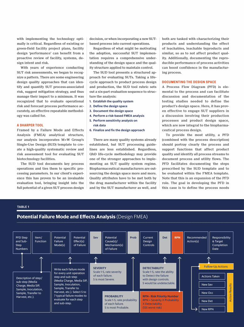
Potential Failure Mode and Effects Analysis (Design FMEA)
PFD Step and Sub- Step Numbers
Description of step/sub-step (Media Charge, Media SIP,Sample, Inoculation, Sample, Transfer to Harvest, etc.).
Write each failure mode for every unit operation step and sub-step (Media Charge, Media SIP, Sample, Inoculation,Sample, Transfer to Harvest, etc.). Select 5 to 7 typical failure modes to evaluate for each step and sub-step.
Potential Failure Mode(s)
Item/ Function
Potential Effect(s) of Failure
Current Design Controls
Recommended Action(s)
Responsibility & Target Completion Date
Follow-Up Actions
Potential Cause(s)/ Mechanism(s) of Failure
Sev Prob Det RPN
TABLE 1
Actio
n Re
sults
Actions Taken
New Sev
New Occ
New Det
New RPN
SEVERITYScale 1-5, rate severity of each failure. 5 is most Severe.
DETECTABILITY Scale 1-5, rate the ability to Detect the failure with design controls. 5 would be undetectable.
PROBABILITYScale 1-5, rate probability of each failure. 5 is most Probable.
RPN– Risk Priority NumberRPN = Severity X Probability X Detectability (125 worst risk)
116 PHARMA’S ALMANAC GLOBAL PHARMACEUTICAL SUPPLY CHAIN TRENDS Q1 2017
and work out those details — the ones that
can add significant cost savings to the
process design.
The requirement of the PFD in building
the SUD template is to capture all the criti-
cal steps and operations that pose a risk
within the model process to be included
in the evaluation. Therefore raw material,
heat-up, cool-down, reactions, transfers,
changeover, etc., all must be captured in
the PFD stream identifications so that the
operation can be evaluated within the SUD
template and FMEA analysis.
COLLECTING INFORMATION
FOR THE SUD TEMPLATE
The SUD template is used to document all
critical attributes of the process facility.
Here, process steps are walked through
while adding details to the steps identi-
fied in the PFD. The steps, sub-steps and
sub-sub-steps will cover all areas of risk
for the inventory, including set-up, run
and retirement of the process(es). The
process is followed from raw materials
through final Vial Fill/Packaging, Bulk
Fill/Storage, Freeze-Thaw and Shipment.
FMEA is a tried and true methodology
that M+W Group has used successfully for
many years. The tool provides an ideal for-
mat to compare process parameters iden-
tified within the SUD template with the
associated risks identified in the FMEA
analysis. This numerical evaluation of risk,
including thorough cross-references to
process details, offers tremendous trans-
parency of all the potential issues SUT
implementation may present.
RISK EVALUATION
Selecting failure modes carefully is criti-
cal to a successful FMEA, as is consis-
tent, fair evaluation of each of the tasks
or functions with potential for risk mitiga-
tion. Best practice recommends that the
project team evaluating the risk also be in-
volved in brainstorming the failure modes.
This will only add to the understanding of
the FMEA template prior to filling out the
risk evaluation.
Common failure modes familiar to SUT
process engineers often considered in
M+W Group analysis include:
• Power Loss• Operator Error • Adverse Leachable• Bag Tear/Leak• Tube or Fitting Wear or Leak• Over Pressure • Material Compatibility
Although strictly ensuring uniform,
consistent ratings is not possible, M+W
Group employs a five-point system to help
minimize the guessing between hazard rat-
ings. To be effective, we try to keep evalu-
ation simple. For example, address the
risk as “it is,” “it is not” and “it may be.” By
starting at this point, using a 5, 3 or 1, then
the degrees can be determined (4 or 2 lean-
ing one direction or another). It is best
to filter the list to include all of one fail-
ure mode so that the evaluator’s frame of
mind does not wander during the evalua-
tion. Noting carefully what is being con-
sidered in the risk ranking can help to
make the evaluations more consistent
during the evaluation.
It is key that no mitigation is included
during the first evaluation, as this would
unfairly reduce the perceived risk. The
Risk Priority Number (RPN) is established
by multiplying the Severity (S) times the
Probability (P) times the Detectability (D).
RPN = S � P � D
The max RPN value of 125 can be ob-
tained.
Note that S is the most difficult pa-
rameter of RPN to improve. P may be im-
proved, although typically this parameter
has already been optimized. Detectability
is the most likely parameter to improve
through testing or PAT integration.
RISK MITIGATION
Once the FMEA evaluation is completed,
the SUD template is expanded with the
FMEA failure modes per evaluation step
and then updated with the FMEA RPN val-
ues. The product of S and P forms a fairly
firm value of risk. For executive and opera-
tions managers using this methodology,
one can provide a distinct line between ac-
ceptable risk and unacceptable risk.
Facility design can benefit from a pro-
active review of facility, systems, design
intent and risk. Once accomplished, po-
tential risk-mitigation plans can be put
in place to reduce the risk to acceptable
limits. Use of the SUD tool can document
the key process operations and tie them to
specific processing parameters. For M+W
Group, this has proven to be a valuable
evaluation tool when reviewing the eco-
nomic suitability and quality potential of
integrating SUTs into the existing process
or incorporating SUTs into an entirely new
process. P
Carl Carlson Director, Bioprocess Design and Technology
Mr. Carlson has more than 30 years of industrial process engineering experience. His expertise is in process development and production operations, process and facility design, integration of manufacturing expertise, process engineering, process control and cGMP compliance, providing an ideal background for quality facility and process design. Mr. Carlson’s four years of operations experience at DuPont followed by 26 years of design experience with architectural and engineering companies has involved bridging communication across executive, scientific and operations levels of organizations.