QForm3D –cost effective simulation tool for metal forming technology S. Stebunov, N. Biba QuantorForm Ltd. e-mail: [email protected], www.qform3d.com Summary QForm3D is a forging simulation program that meets the highest demand of the metal forging industry. The world-wide experience of QForm implementation covers different metal forming processes including hot and cold forging, net shape forging, open die forging, reducer rolling etc. The simulation is performed through the whole technological chain including controlled heating, passing through several forming operations, trimming, cooling. In addition to open and closed die forging operations it can simulate complex profiles extrusion and different kinds of rolling processes where the billet is deformed either by longitudinal or transversal rotation of the tools. If required the program simulates microstructural evolution through the whole technological chain including grain size prediction during the forming operations and pauses between blows. After completion of the forging it is possible to simulate heat treatment (quenching) for predicting properties of the finish product (phase composition, hardness, residual stresses etc.). To fit current demand for low cost and quick development of new products the program requires very short introductory period and does not need special qualification besides of experience in metal forming technology. QForm is easily implemented for optimization of forging technology even at small and medium size companies due to fast data setting, quick and fully automated work. By means of parallelized computations and use of 64-bit platform it is possible to run on a PC very complex simulations of the big crankshafts, steering arms and other critical parts for automotive and aerospace industries. Introduction QForm 3D is a forging simulation program designed by forgers to meet the demands of the forge engineer. The program behaves like a virtual forging shop where the user has control of all the variables. He can develop the sequence of technological operations required to produce the forging including upsetting, blocker, and finisher blows selecting the required equipment and the lubricant used. Preliminary and intermediate operations like reducer rolling (see Fig. 1), heating, cooling and flash trimming also can be included in the technological chain. a. b. c. Fig. 1. The simulation of four pass reducer rolling by QForm: (a) the program window with the rolls and the billet; (b) the simulated billet shapes; (c) the experimental billet shapes (photo).
Transcript
QForm3D –cost effective simulation tool for metal forming technology
QForm3D is a forging simulation program that meets the highest demand of the metal forgingindustry. The world-wide experience of QForm implementation covers different metal formingprocesses including hot and cold forging, net shape forging, open die forging, reducer rolling etc.The simulation is performed through the whole technological chain including controlled heating,passing through several forming operations, trimming, cooling. In addition to open and closeddie forging operations it can simulate complex profiles extrusion and different kinds of rollingprocesses where the billet is deformed either by longitudinal or transversal rotation of the tools.If required the program simulates microstructural evolution through the whole technologicalchain including grain size prediction during the forming operations and pauses between blows.After completion of the forging it is possible to simulate heat treatment (quenching) forpredicting properties of the finish product (phase composition, hardness, residual stresses etc.).To fit current demand for low cost and quick development of new products the program requiresvery short introductory period and does not need special qualification besides of experience inmetal forming technology. QForm is easily implemented for optimization of forging technologyeven at small and medium size companies due to fast data setting, quick and fully automatedwork. By means of parallelized computations and use of 64-bit platform it is possible to run on aPC very complex simulations of the big crankshafts, steering arms and other critical parts forautomotive and aerospace industries.
Introduction
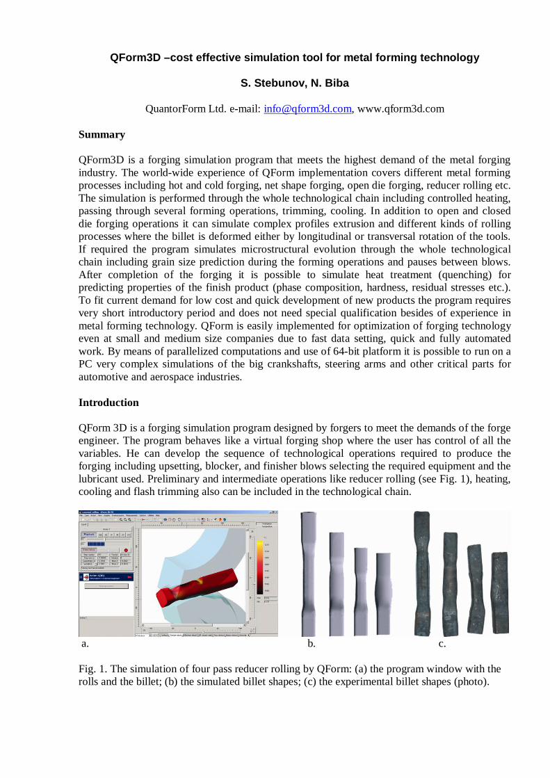
QForm 3D is a forging simulation program designed by forgers to meet the demands of the forgeengineer. The program behaves like a virtual forging shop where the user has control of all thevariables. He can develop the sequence of technological operations required to produce theforging including upsetting, blocker, and finisher blows selecting the required equipment and thelubricant used. Preliminary and intermediate operations like reducer rolling (see Fig. 1), heating,cooling and flash trimming also can be included in the technological chain.
a. b. c.
Fig. 1. The simulation of four pass reducer rolling by QForm: (a) the program window with therolls and the billet; (b) the simulated billet shapes; (c) the experimental billet shapes (photo).
What are the most attractive features of QForm for the users?
First of all the program can be quickly implemented. It has very clear and transparent interfacefor the source data setup and simulation control. Integrated architecture of the program withoutseparate pre- and post processor makes the work very comfortable. The results output isconcurrent with the simulation progress hat helps to understand simulation and learn it easily.New people can quickly start to work. People who may need to use the simulation from time totime also feel themselves very comfortably when they come back to the program.
Set up of a simulation is very fast. The source data are prepared in just a few minutes by meansof a self-explanatory Data Preparation Wizard. This wizard takes you step by step through thesimulation set up and reduces the opportunity for mistakes. Direct and immediate access to thesource data structure is provided by a property editor. Thus the process of setting up a newvariation of the project can be created in one click.
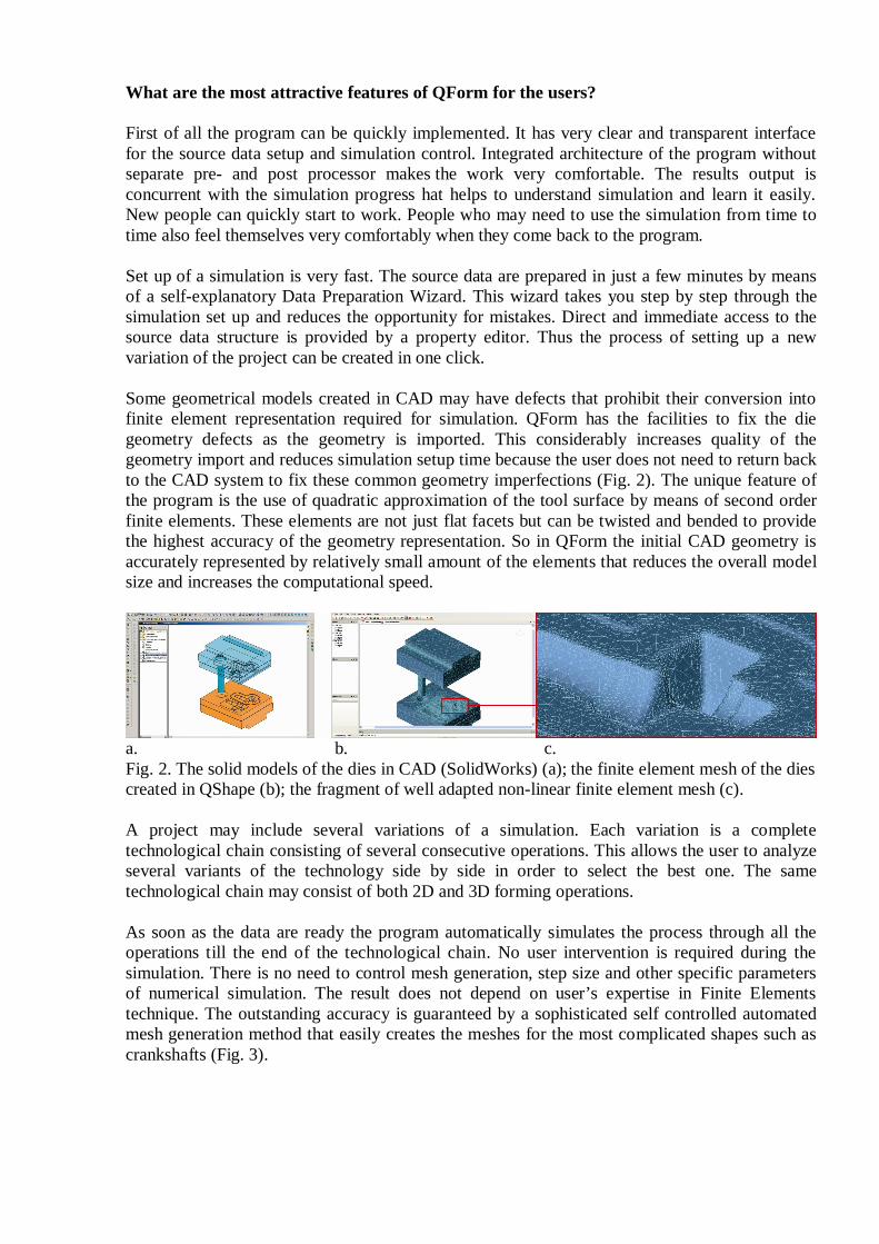
Some geometrical models created in CAD may have defects that prohibit their conversion intofinite element representation required for simulation. QForm has the facilities to fix the diegeometry defects as the geometry is imported. This considerably increases quality of thegeometry import and reduces simulation setup time because the user does not need to return backto the CAD system to fix these common geometry imperfections (Fig. 2). The unique feature ofthe program is the use of quadratic approximation of the tool surface by means of second orderfinite elements. These elements are not just flat facets but can be twisted and bended to providethe highest accuracy of the geometry representation. So in QForm the initial CAD geometry isaccurately represented by relatively small amount of the elements that reduces the overall modelsize and increases the computational speed.
a. b. c.Fig. 2. The solid models of the dies in CAD (SolidWorks) (a); the finite element mesh of the diescreated in QShape (b); the fragment of well adapted non-linear finite element mesh (c).
A project may include several variations of a simulation. Each variation is a completetechnological chain consisting of several consecutive operations. This allows the user to analyzeseveral variants of the technology side by side in order to select the best one. The sametechnological chain may consist of both 2D and 3D forming operations.
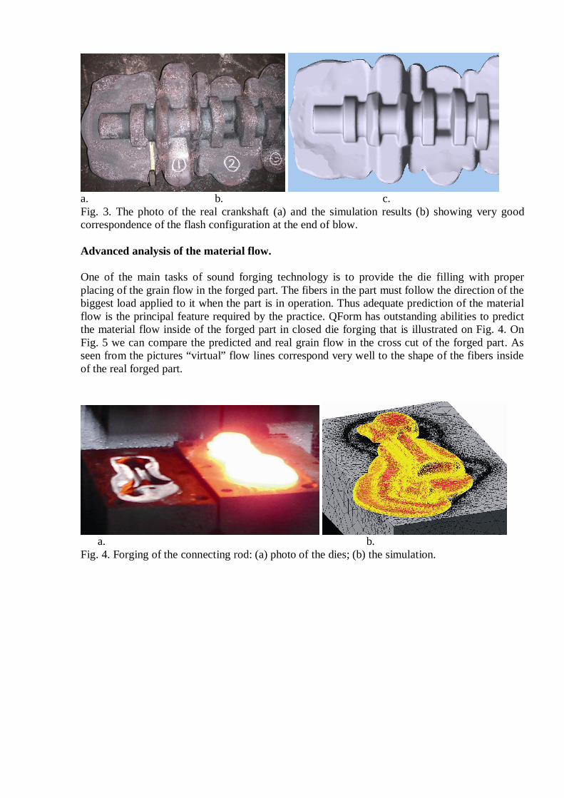
As soon as the data are ready the program automatically simulates the process through all theoperations till the end of the technological chain. No user intervention is required during thesimulation. There is no need to control mesh generation, step size and other specific parametersof numerical simulation. The result does not depend on user’s expertise in Finite Elementstechnique. The outstanding accuracy is guaranteed by a sophisticated self controlled automatedmesh generation method that easily creates the meshes for the most complicated shapes such ascrankshafts (Fig. 3).
a. b. c.Fig. 3. The photo of the real crankshaft (a) and the simulation results (b) showing very goodcorrespondence of the flash configuration at the end of blow.
Advanced analysis of the material flow.
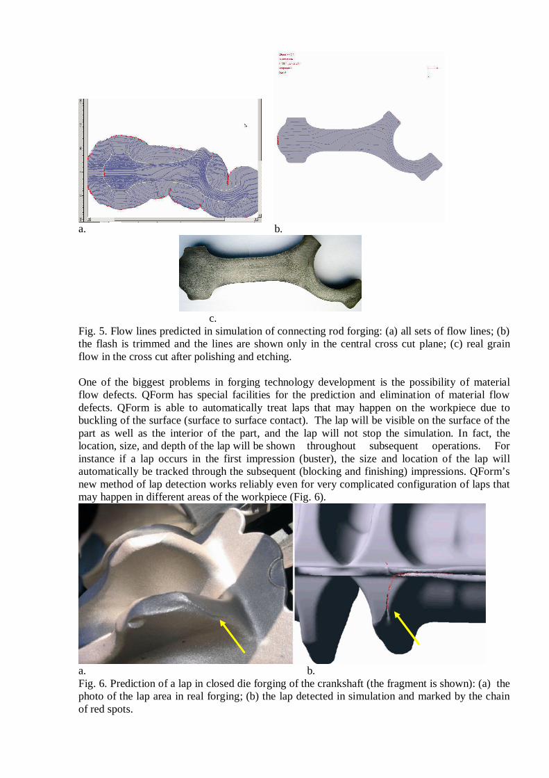
One of the main tasks of sound forging technology is to provide the die filling with properplacing of the grain flow in the forged part. The fibers in the part must follow the direction of thebiggest load applied to it when the part is in operation. Thus adequate prediction of the materialflow is the principal feature required by the practice. QForm has outstanding abilities to predictthe material flow inside of the forged part in closed die forging that is illustrated on Fig. 4. OnFig. 5 we can compare the predicted and real grain flow in the cross cut of the forged part. Asseen from the pictures “virtual” flow lines correspond very well to the shape of the fibers insideof the real forged part.
a. b.Fig. 4. Forging of the connecting rod: (a) photo of the dies; (b) the simulation.
a. b.
c.Fig. 5. Flow lines predicted in simulation of connecting rod forging: (a) all sets of flow lines; (b)the flash is trimmed and the lines are shown only in the central cross cut plane; (c) real grainflow in the cross cut after polishing and etching.
One of the biggest problems in forging technology development is the possibility of materialflow defects. QForm has special facilities for the prediction and elimination of material flowdefects. QForm is able to automatically treat laps that may happen on the workpiece due tobuckling of the surface (surface to surface contact). The lap will be visible on the surface of thepart as well as the interior of the part, and the lap will not stop the simulation. In fact, thelocation, size, and depth of the lap will be shown throughout subsequent operations. Forinstance if a lap occurs in the first impression (buster), the size and location of the lap willautomatically be tracked through the subsequent (blocking and finishing) impressions. QForm’snew method of lap detection works reliably even for very complicated configuration of laps thatmay happen in different areas of the workpiece (Fig. 6).
a. b.Fig. 6. Prediction of a lap in closed die forging of the crankshaft (the fragment is shown): (a) thephoto of the lap area in real forging; (b) the lap detected in simulation and marked by the chainof red spots.
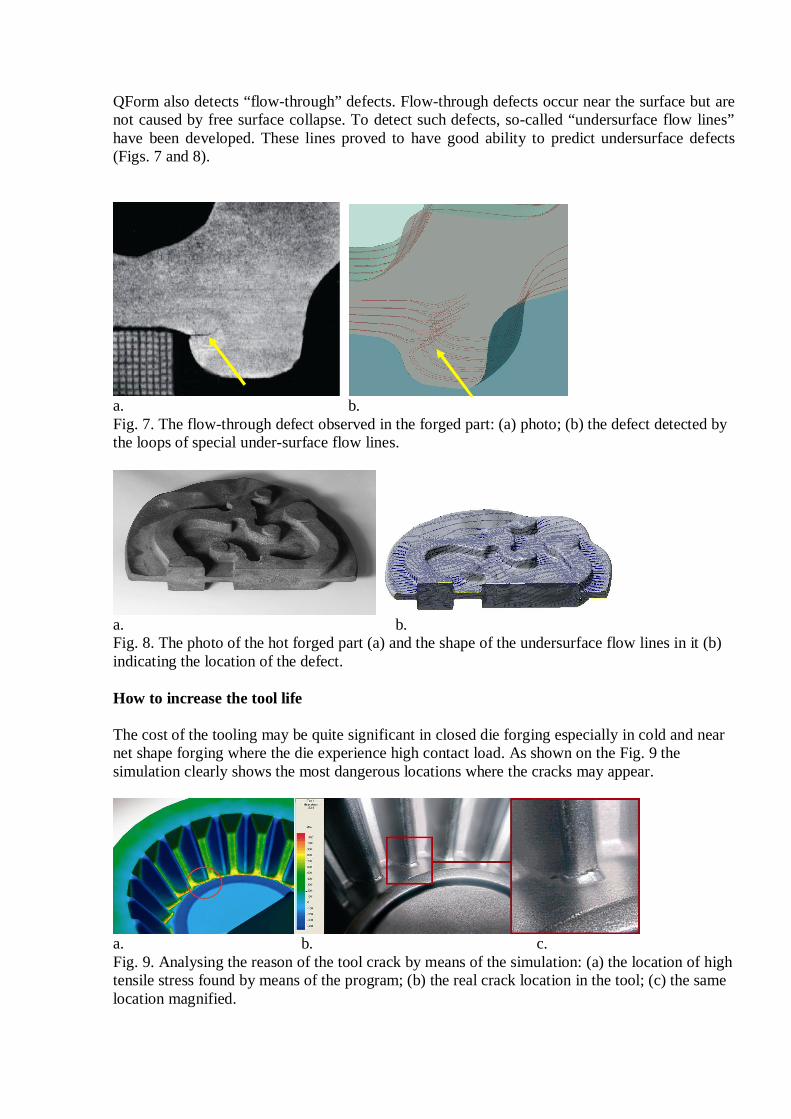
QForm also detects “flow-through” defects. Flow-through defects occur near the surface but arenot caused by free surface collapse. To detect such defects, so-called “undersurface flow lines”have been developed. These lines proved to have good ability to predict undersurface defects(Figs. 7 and 8).
a. b.Fig. 7. The flow-through defect observed in the forged part: (a) photo; (b) the defect detected bythe loops of special under-surface flow lines.
a. b.Fig. 8. The photo of the hot forged part (a) and the shape of the undersurface flow lines in it (b)indicating the location of the defect.
How to increase the tool life
The cost of the tooling may be quite significant in closed die forging especially in cold and nearnet shape forging where the die experience high contact load. As shown on the Fig. 9 thesimulation clearly shows the most dangerous locations where the cracks may appear.
a. b. c.Fig. 9. Analysing the reason of the tool crack by means of the simulation: (a) the location of hightensile stress found by means of the program; (b) the real crack location in the tool; (c) the samelocation magnified.
The program also possesses more enhanced facilities for simulation of the dies. Conditions of diesupport can be specified interactively and deformed shape of the dies can be displayed. Thesimulation allows analysing stress distribution in the die blocks, the distribution of the abrasivedie wear and to find ways to reduce stresses and to extend the tool life (Fig. 10).
a. b. c.Fig. 10. The effective stress distribution in the upper (a) and the lower (c) dies and thetemperature distribution in the forged part (b).
In some cases the die deflection may significantly influence the shape of the forged product. Itmay happen, for example, in case of forging of the thin blades when the blade profile is to beuses as forged. To fit the demand for precise forging technology a new option for coupledmechanical and thermal simulation has been recently developed and added to the program.
The user can improve tool life by modifying the geometry (for example, by increasing the filletsin critical points), using shrink fitting or making assembly dies with high duty material inserts.By using simulation the optimal solution can be found very quickly and inexpensively.
Simulation of microstructure evolution and heat treatment
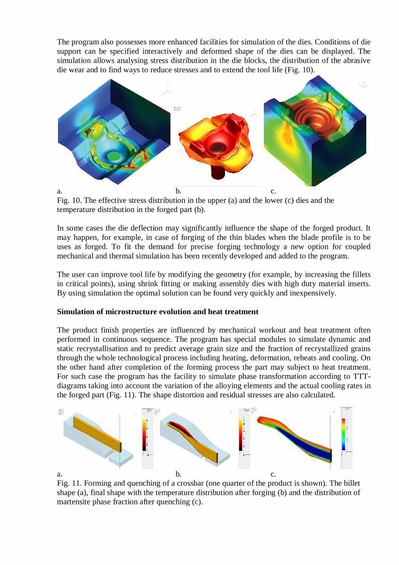
The product finish properties are influenced by mechanical workout and heat treatment oftenperformed in continuous sequence. The program has special modules to simulate dynamic andstatic recrystallisation and to predict average grain size and the fraction of recrystallized grainsthrough the whole technological process including heating, deformation, reheats and cooling. Onthe other hand after completion of the forming process the part may subject to heat treatment.For such case the program has the facility to simulate phase transformation according to TTT-diagrams taking into account the variation of the alloying elements and the actual cooling rates inthe forged part (Fig. 11). The shape distortion and residual stresses are also calculated.
a. b. c.Fig. 11. Forming and quenching of a crossbar (one quarter of the product is shown). The billetshape (a), final shape with the temperature distribution after forging (b) and the distribution ofmartensite phase fraction after quenching (c).
High economical efficiency
From the user’s point of view QForm works seamlessly as a handy simulation tool for virtualtryouts of the forging process. It provides a fast return of investment by means of speeding upthe technology development and reducing production costs. The program has already added realand valuable competitive advantages to many forging companies.