Page 1
Qinrong Yu Report of MEng Project PIC32 Development
1
PIC32 DEVELOPMENT
A Design Project Report
Presented to the School of Electrical and Computer Engineering
of Cornell University
in Partial Fulfillment of the Requirements for the Degree of
Master of Engineering, Electrical and Computer Engineering
Submitted by
Qinrong Yu
MEng Field Advisor: Prof. Bruce R Land
Degree Date: January 2016
Page 2
Qinrong Yu Report of MEng Project PIC32 Development
2
Abstract
Master of Engineering Program
School of Electrical and Computer Engineering
Cornell University
Design Project Report
Project Title: PIC32 Development
Author: Qinrong Yu
Abstract:
PIC32 is Microchip’s 32-‐bit microcontroller. It offers high performance and all tools to develop
embedded projects. It is widely used as learning materials in microcontroller courses. ECE4760
is upgrading its learning material now. They are going to adopt PIC32 microcontroller as study
object. The aim of this project is to provide a complete USB module that can be used in the
course directly. This project mainly focuses on the development of USB module of PIC32,
enabling the USB port to transfer data between end devices (mouse and keyboard) and the
microcontroller PIC32MX250F128B. Both software code and hardware verification are
necessary for the project. Certain data transfer functions were realized. When a devices such as
a keyboard or a mouse plug in to the USB interface of PIC32, PIC32 is able to get every letter we
type on a keyboard or get every input command we click on a mouse.
Keywords:
PIC32, USB
Page 3
Qinrong Yu Report of MEng Project PIC32 Development
3
Executive Summary PIC32 microcontroller is a powerful, 32-‐bit CPU with many peripherals and available libraries.
It is a good tool for students to understand and practice microcontroller. This project mainly
focuses on the development of USB module of PIC32, enabling the USB port to transfer data
between end devices (mouse and keyboard) and the microcontroller PIC32MX250F128B.
Both software code and hardware verification are necessary for the project. Certain data
transfer functions were realized. When a devices such as a keyboard or a mouse plug in to the
USB interface of PIC32, PIC32 is able to get every letter we type on a keyboard or get every
input command we click on a mouse.
The final outcome is a finished working USB module and can be used by students in Course
ECE4760 to incorporate into their course work directly.
Approach The approach of the project is shown in the following chart.
The project adopts a development board on which a microcontroller PIC32MX250F128B is
integrated. We used the Microstick II from Microchip Technology Inc. as the development board.
Besides, as this project is to enable data transfer of USB port, a USB board is necessary. There
are a variety of USB boards on market. For this designing project, USB Type A Female Breakout
board is used. The USB picture is shown in Figure.1. It has a USB interface requiring 2 power
wires (VCC, GND) and 2 data wires (D+ and D-‐). For the purpose of showing results in real time,
a serial port board is also necessary. The serial port is used to enable communication between
the microcontroller and a computer, thus enabling displaying results on the screen of a
computer. Putty application is used to show the results [1].
1 • Learn from the PIC32 library
2 • Compile the dirmware successfully
3 • Realize the hardware
4 • Simplify the software code
5 • Write simple and explicit documentation
Page 4
Qinrong Yu Report of MEng Project PIC32 Development
4
For developing tools, C is used as the programming language and MPLAB IDE is used as the
development environment [2]. XC32 is used as compiler [3].
The microcontroller acts as the “host” in the USB protocol while end devices such as a keyboard
or a mouse takes the “device” role. The software code part refers to the microchip library. To
start with, I learnt from the PIC32 library and got familiar with USB protocol. Microchip
provides a library containing a variety of application for different series of Microchip
microcontrollers. The library gives clear examples of how to use USB modules and explains how
USB protocol works well. The USB applications provided by the library, however, can’t work
properly on our board. The possible explanation is that the library is for all series of
microcontrollers. Some adjustments were made to make the applications work on our specific
board. The adjustments will be stated in the section of key issues addressed.
After the completion of software code, the hardware verification was carried out. Firstly, the
microcontroller should be able to work normally. A power supply of 3.3V should be given to the
Vusb3.3v pin to enable USB function of PIC32. The pin diagram of PIC32MX250F128B is shown
in Figure.2. Then the external USB board should be connected to the microcontroller correctly.
The data wires (D+, D-‐) should be connected to PIN 21, PIN 22 of PIC32MX250F128B and the
power supply wires (VCC, GND) should be connected to the board to share the same ground
power with the microcontroller. (Shown in Figure.1) After that, serial port board should be
connected to the microcontroller. The data wires (Rx, Tx) were connected to PIN 17, PIN 25 of
PIC32.
Then, debug the program to ensure the USB interface works properly to transfer data between
end devices and the microcontrollers. The debugging process was actually carried out step by
step. I first debug microcontroller and did some simple tests to prove that PIC32 was working.
Then after USB board was connected, I tested to see if the board was working appropriately. As
the data transmitted from the end devices was stored in data buffers and parsed according to
the USB protocol, I checked the related buffers in the variable window to see whether the
transmitted data was correct. For instance, when a mouse was clicked on a right button and
moved to the right, certain bit indicating the right button in the data buffer should be set to 1
and the coordinate of the mouse should be set the current location. Then, after serial port board
Page 5
Qinrong Yu Report of MEng Project PIC32 Development
5
was connected, I tested to see if the results could be displayed on the screen of the computer
correctly. This step-‐by-‐step debugging approach enabled me to find errors or mistakes one by
one, and helped me a lot. For example, there was a time when no results were shown on the
screen. Since I knew that PIC32 and USB board were both working fine, I focused on serial port
board only, which was much more efficient than checking everything.
Figure 1. USB Type A Female Breakout Board [4]
Figure 2. USB to Serial Breakout -‐ CP2102 [5]
Page 6
Qinrong Yu Report of MEng Project PIC32 Development
6
Microstick II PIC32 PDIP
Figure.2 PIC32 Pin Diagram [6]
Key issues addressed
Hardware Connection I encountered a problem when carrying out hardware connection. I did the connection
according to the pin diagram on the datasheet, but the circuits didn’t work anyway. The voltage
detected on the pins was not what it should have been. It turned out that the pin diagram of
PIC32MX250F128B in the data sheet didn’t correspond to the real pin design on the
development board. The real layout pin diagram should have been the one that I referred to.
After I re-‐did the connection, the voltage on each pin was correct.
External Power Another issue is that the USB board requires a power supply of 5V. As the microcontroller can
merely provide a power supply of 3.3V, which is not enough for the USB board, an external
power supply is necessary. And also, the USB port and the development board should share the
same ground.
Oscillator Configuration After all the hardware connection was done, I started to debug the program. However, the
message “The target device is not ready for debugging. Please check your configuration bit
Page 7
Qinrong Yu Report of MEng Project PIC32 Development
7
settings and program the device before proceeding” was shown on the output window every
time I tried to initiated a debug. I referred to the documents and found that there might be 3
possible causes for this problem. Firstly, the oscillator might have not been operating correctly,
so that the microcontroller was not able to run the code. Then, I needed to ensure that the
debug pins set in the configuration bits is the same one that the debugger (starter kit PKOB ) on
the development board was physically connected to. Last but not least, the inappropriate load
on the debug pins might have contributed to the problem. To solve the problem, I started with
checking the oscillator first. I found that the firmware set the system clock to be 60Mhz.
However, the configuration bits for system clock were set as follows:
#pragma config FNOSC = FRCPLL // Oscillator Selection, select internal oscillator
#pragma config FPLLMUL = MUL_20 // PLL Multiplier
#pragma config FPLLIDIV = DIV_2 // PLL Input Divider
#pragma config FPLLODIV = DIV_1 // PLL Output Divider
From the oscillator diagram, a part of which is shown in Figure.3, we can easily find that the
system clock is get from the equation:
𝑆𝑌𝑆𝐶𝐿𝐾 =𝑂𝑠𝑐𝐹𝑟𝑒𝑞 × 𝐹𝑃𝐿𝐿𝑀𝑈𝐿𝐹𝑃𝐿𝐿𝐼𝐷𝐼𝑉 × 𝐹𝑃𝐿𝐿𝑂𝐷𝐼𝑉
However, with the default configuration bits, the system clock would be 𝑆𝑌𝑆𝐶𝐿𝐾 = !!"# × !"! × !
=
80𝑀𝐻𝑧, which was not corresponding with 60MHz. Therefore, I modified the configuration bits
to the following and the system clock was 60MHz.
#pragma config FPLLMUL = MUL_15 // PLL Multiplier
#pragma config FPLLIDIV = DIV_2 // PLL Input Divider
#pragma config FPLLODIV = DIV_1 // PLL Output Divider
Then for the debug pins, I found that there was a switch SW2 on the development board
controlling which pair of pins to use. SW2 was switched to PEGCA and PEGDA side, so I modified
the configuration bit from
#pragma config ICESEL = ICS_PGx2 // ICE/ICD Comm Channel Select
to
#pragma config ICESEL = ICS_PGx1 // ICE/ICD Comm Channel Select.
After all the modification was done, the debug process was able to start without any error
message.
Page 8
Qinrong Yu Report of MEng Project PIC32 Development
8
Figure.3 Oscillator diagram [6]
During debugging, I found that whenever I plugged a mouse into the USB port, the USB module
of the microcontroller was not able to detect the device. The state machine was always stuck in
state DEVICE_NOT_CONNECTED. I checked the diagram of USB module and found that the
Page 9
Qinrong Yu Report of MEng Project PIC32 Development
9
possible cause might be the use of internal oscillator FRC. USB module could not use FRC. The
reason is that the internal oscillator is fed into USB module directly without passing through a
PLL as we can see in Figure 4. The oscillator part of PIC32 USB interface diagram is shown in
Figure 4. Therefore, 8MHz of FRC is far from enough to provide the USB module with the
required 48MHz clock. The possible solution is to put an external oscillator to the OSC1 and
OSC2 pins with some configuration circuits. As the USB module needs a 48 MHz clock, the
external oscillator of 8 MHz will be adequate. To ensure the external oscillator work properly,
the ground should be placed as close as possible to the oscillator. Then the configuration bits
were modified to be:
#pragma config UPLLEN = ON // USB PLL Enable
#pragma config UPLLIDIV = DIV_2 // USB PLL Input Divider
#pragma config FNOSC = PRIPLL // Oscillator Selection: select primary oscillator
// As the USB PLL is by default set to be 24 and then divided by 2 (shown in Figure 3), there
is no need to specifically set USBPLL.
As for the configuration circuits for the external oscillator, the OSC1 and OSC2 pins should both
be connected to a capacitor and then connected to the ground. The configuration circuit is
shown in Figure 3. The capacitors would be 20~30 pF for an oscillator of 8MHz. Since the
capacitors are so small that the breadboard can provide enough capacitance, so I just put an
8MHz crystal oscillator on OSC1 and OSC2 pins without any additional connections. Resistor Rs
may be required cut crystals or to eliminate clipping. RP is used to increase oscillator circuit
gain, add a parallel resistor, with a value of 1 MΩ. [6]
Page 10
Qinrong Yu Report of MEng Project PIC32 Development
10
Figure 4. PIC32 USB OTG Interface Diagram (Clock Part)
Serial Port Configuration
Serial port board has two data wires Rx and Tx. Two pins on PIC32 should be mapped to be TX
and RX[8]. The configuration part is as following.
//specify PPS group, signal, logical pin name
PPSInput (2, U2RX, RPB8); //Assign U2RX to pin RPB8 -‐-‐ Physical pin 17 on 28 PDIP
PPSOutput(4, RPB14, U2TX); //Assign U2TX to pin RPB14 -‐-‐ Physical pin 25 on 28 PDIP
Then configure UART communication in a higher lever[8]. The code part is as following.
UARTConfigure(UART2, UART_ENABLE_PINS_TX_RX_ONLY);
UARTSetLineControl(UART2, UART_DATA_SIZE_8_BITS | UART_PARITY_NONE |
UART_STOP_BITS_1);
UARTSetDataRate(UART2, PB_FREQ, BAUDRATE);
UARTEnable(UART2, UART_ENABLE_FLAGS(UART_PERIPHERAL | UART_RX | UART_TX));
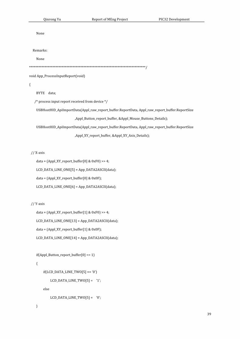
Data Processing
For mouse data processing, the input report parsing process didn’t get out all the data I needed.
It only produced data of the button clicked and the movement of scroll wheel. But the
movement of mouse is also a key parameter. Therefore, I looked into the data parsing process
Page 11
Qinrong Yu Report of MEng Project PIC32 Development
11
and got the data of relative coordinate of X-‐Y axis in the input report. In addition, the output
format is not easy to read. So I reorganize the output data in a way that data for each button or
movement is clear.
The Button data is stored in Appl_Button_report_buffer, where data of left button stores in the
0th bit and data of right button stores in the 1th bit. The scroll weel data is stored in
Appl_raw_report_buffer.ReportData[3]. The movement of mouse representing in X-‐Y axis is
stored in Appl_XY_report_buffer, where data of X-‐axis is stored in bit 0 and that of Y-‐axis is
stored in bit 1. The modified code segment is shown in the following. The data is much easy to
read.
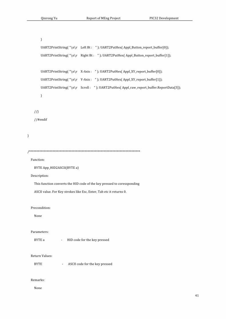
UART2PrintString( "\n\r Left Bt : " ); UART2PutHex( Appl_Button_report_buffer[0]);
UART2PrintString( "\n\r Right Bt : " ); UART2PutHex( Appl_Button_report_buffer[1]);
UART2PrintString( "\n\r X-‐Axis : " ); UART2PutHex( Appl_XY_report_buffer[0]);
UART2PrintString( "\n\r Y-‐Axis : " ); UART2PutHex( Appl_XY_report_buffer[1]);
UART2PrintString( "\n\r Scroll : " ); UART2PutHex( Appl_raw_report_buffer.ReportData[3]);
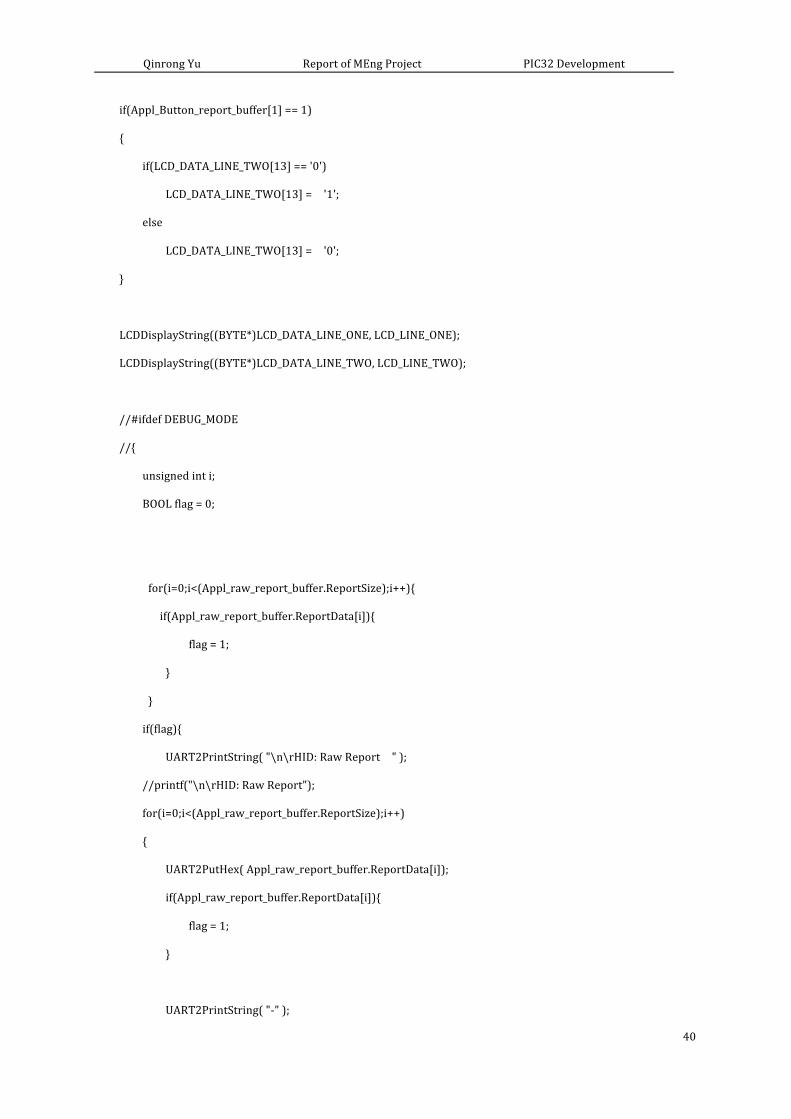
Besides, the results are shown on the screen every certain interval, which could make our
output data very huge and useless. What I really need is the updated data when there is any
operation on the mouse. So I added a Boolean type flag to distinguish between useful data and
useless data, and only showed the data when there was any change. The code is shown in the
following.
unsigned int i;
BOOL flag = 0;
for(i=0;i<(Appl_raw_report_buffer.ReportSize);i++){
if(Appl_raw_report_buffer.ReportData[i]){
flag = 1;
}
}
if(flag){
UART2PrintString( "\n\rHID: Raw Report " );
for(i=0;i<(Appl_raw_report_buffer.ReportSize);i++)
Page 12
Qinrong Yu Report of MEng Project PIC32 Development
12
{
UART2PutHex( Appl_raw_report_buffer.ReportData[i]);
if(Appl_raw_report_buffer.ReportData[i]){
flag = 1;
}
UART2PrintString( "-‐" );
}
UART2PrintString( "\n\r Left Bt : " ); UART2PutHex( Appl_Button_report_buffer[0]);
UART2PrintString( "\n\r Right Bt : " ); UART2PutHex( Appl_Button_report_buffer[1]);
UART2PrintString( "\n\r X-‐Axis : " ); UART2PutHex( Appl_XY_report_buffer[0]);
UART2PrintString( "\n\r Y-‐Axis : " ); UART2PutHex( Appl_XY_report_buffer[1]);
UART2PrintString( "\n\r Scroll : " ); UART2PutHex( Appl_raw_report_buffer.ReportData[3]);
}
The final output data for mouse is shown in Figure 9.
For the keyboard part, the input report parsing function didn’t handle some important special
characters including backspace, space. I added some functions to handle these corner cases. In
addition, I’m not confortable with the output format either. So I reorganized the format to
display whatever I typed on the screen and got rid of useless displayed information. The
following codes were added to handle some important characters.
if(a == 0x2c){ // handle space command
return(0x20);
}
if(a == 0x2a){ // handle backspace command
return(0x08) ;
}
The final output data for keyboard is shown in Figure 10.
Page 13
Qinrong Yu Report of MEng Project PIC32 Development
13
Results The final outcome is a finished working USB module. The picture of the development board is
shown in the Figure 6.
Figure 6. The picture of the development board PuTTY is used to display the results. The serial line should be set properly. And the baud rate
should be set the same as that of PIC32. In my case, it’s 9600. The putty window is shown in
Figure 7.
The displayed information shows that the microcontroller is able to handle typing on keyboard
correctly, including characters (both upper and lower cases), digits, symbols and some special
characters such as Caps lock, Num lock, Space and Backspace and so on. The displayed
information is shown in Figure 8. If Caps lock is typed, the following characters will all shown in
upper cases. If Num lock is typed, the microcontroller won’t handle input from the digits area,
which is on the right of the keyboard. The microcontroller can respond immediately on every
input.
USB port
Used to connect to
end devices
Serial port
Connect to a
computer to show
results
External power
5v for USB port
Microstik II
Featuring microcontroller
PIC32MX250F128B
Page 14
Qinrong Yu Report of MEng Project PIC32 Development
14
Figure 7. The configuration of PuTTY
Figure 8. The screen shot of demo of keyboard
Page 15
Qinrong Yu Report of MEng Project PIC32 Development
15
The tests for the mouse part were designed to check button clicks first, then scroll wheel, and
finally X-‐Y axis movements. The results for button clicks were shown in Figure 9. I clicked left
button and right button in order. The results show that the microcontroller can process button
click correctly and in the correct order.
Figure 9. The screen shot of button clicks on mouse
For scroll wheel tests, I scrolled up and down. The results were shown in Figure 10. When I
scrolled up, the data in Scroll line showed a positive integer. In this test, I scrolled up a little bit,
so the integer is only 0x01. When I scrolled down, the results showed a negative integer. The
negative indicates the scrolling direction, and the absolute value indicates how much I scrolled.
As I scrolled down a little bit, the result is 0xFF (absolute value: 0x01). After that, I tested how
microcontroller reacted if I scrolled the scroll wheel with larger movement. The result is shown
in Figure 11. The results display larger values as integer 0x02 when I scrolled up, and integer
0xFA When I scroll down (absolute value 0x06).
The tests and results shows that the microcontroller can process scroll wheel commands
correctly. PIC32 is able to distinguish different scrolling directions (up and down), and different
scrolling length.
For mouse movement tests, I moved the mouse to different directions and checked the results
to see if it matched. The results were signed integers. Directions were distinguished between
Page 16
Qinrong Yu Report of MEng Project PIC32 Development
16
positive and negative integers. Right and down movements were in positive integers while left
and up in negative. And the absolute values gave the relative movement position. Since the
movement detection is very sensible, there would be a series of results shown on the screen
with a little move. So I write the results into log for the purpose of checking. The results are
shown in Figure 12. The results shows that the microcontroller can process mouse movements
correctly.
Figure 10. The screen shot of scroll wheel on mouse (a)
Page 17
Qinrong Yu Report of MEng Project PIC32 Development
17
Figure 11. The screen shot of scroll wheel on mouse (b)
Page 18
Qinrong Yu Report of MEng Project PIC32 Development
18
Figure 12. The screen shot of log of mouse movements
Conclusions PIC32 is able to process end devices (mouse and keyboard) request immediately and correctly.
The results can be displayed on the screen in real time.
The keyboard demo takes about 48% of the program space of PIC32. The mouse demo takes
about 51% of the program space of PIC32. Although there is still space left for other programs,
it would be better to simplify the firmware to give more space for other programs.
Page 19
Qinrong Yu Report of MEng Project PIC32 Development
19
Acknowledgements I would like to thank my advisor Bruce Land for his advice, encouragement, and continued
support of this project.
I would like to thank Alex Whiteway for his help and kindness of this project.
I would also like to thank my family and friends for their support.
References [1] http://www.putty.org
[2] http://www.microchip.com/pagehandler/en-us/family/mplabx/
[3] http://www.microchip.com/forums/f251.aspx
[4] https://www.sparkfun.com/products/12700?gclid=COGrybOTxMUCFVGRHwodraQAdg
[5] Microchip PIC32MX1XX/2XX family datasheet
[6] PIC32 Family Reference Manual 6 Oscillators
[7] PIC32 Family Reference Manual 27 USB OTG
[8] http://people.ece.cornell.edu/land/courses/ece4760/PIC32/index.html
Page 20
Qinrong Yu Report of MEng Project PIC32 Development
20
Appendix
1. schematic diagram for circuits
2. demo file for mouse and keyboard
/******************************************************************************
USB Mouse Host Application Demo
Description:
This file contains the basic USB Mouse application demo. Purpose of the demo
is to demonstrate the capability of HID host . Any Low speed/Full Speed
USB Mouse can be connected to the PICtail USB adapter along with
Explorer 16 demo board. This file schedules the HID ransfers, and interprets
the report received from the mouse. X & Y axis coordinates, Left & Right Click
received from the mouse are diaplayed on the the LCD display mounted on the
Explorer 16 board. Demo gives a fair idea of the HID host and user should be
Page 21
Qinrong Yu Report of MEng Project PIC32 Development
21
able to incorporate necessary changes for the required application.
Below is the format in which the information received from mouse is displayed
on the LCD didsplay.
-‐-‐-‐-‐-‐-‐-‐-‐-‐-‐-‐-‐-‐-‐-‐-‐
|X: 0x-‐-‐ Y: 0x-‐-‐|
|LFT: -‐ RHT: -‐ |
-‐-‐-‐-‐-‐-‐-‐-‐-‐-‐-‐-‐-‐-‐-‐-‐
Summary:
This file contains the basic USB mouse application.
Remarks:
This demo requires Explorer 16 board and the USB PICtail plus connector.
*******************************************************************************/
//DOM-‐IGNORE-‐BEGIN
/******************************************************************************
* File Name: Mouse_demo.c
* Dependencies: None
* Processor: PIC24FJ256GB110
* Compiler: C30 v2.01
* Company: Microchip Technology, Inc.
Software License Agreement
The software supplied herewith by Microchip Technology Incorporated
*******************************************************************************/
//DOM-‐IGNORE-‐END
//#define _SUPRESS_PLIB_WARNING
#define _SUPPRESS_PLIB_WARNING
Page 22
Qinrong Yu Report of MEng Project PIC32 Development
22
#include <stdlib.h>
#include <string.h>
#include <stdio.h>
#include "GenericTypeDefs.h"
#include "HardwareProfile.h"
#include "usb_config.h"
#include "lcd_demo.h"
#include "USB/usb.h"
#include "USB/usb_host_hid_parser.h"
#include "USB/usb_host_hid.h"
#if defined(__dsPIC33EP512MU810__)||defined(__PIC24EP512GU810__)
/* While using the dsPIC33EPxx USB PIM
* the LCD on the Explorer 16 board may
* not function as expected. The demo
* uses the Explorer 16 UART connector
* to display data. Connect the UART port
* to a PC COM port and run hyperterminal
* at 57600 baud. */
#define DEBUG_MODE
#endif
//#define DEBUG_MODE
// *****************************************************************************
// *****************************************************************************
// Constants
// *****************************************************************************
// *****************************************************************************
// We are taking Timer 3 to schedule input report transfers
Page 23
Qinrong Yu Report of MEng Project PIC32 Development
23
// NOTE -‐ The datasheet doesn't state this, but the timer does get reset to 0
// after a period register match. So we don't have to worry about resetting
// the timer manually.
#define STOP_TIMER_IN_IDLE_MODE 0x2000
#define TIMER_SOURCE_INTERNAL 0x0000
#define TIMER_ON 0x8000
#define GATED_TIME_DISABLED 0x0000
#define TIMER_16BIT_MODE 0x0000
#define TIMER_PRESCALER_1 0x0000
#define TIMER_PRESCALER_8 0x0010
#define TIMER_PRESCALER_64 0x0020
#define TIMER_PRESCALER_256 0x0030
#define TIMER_INTERRUPT_PRIORITY 0x0001
// useful ASCII/VT100 macros for PuTTY
#define clrscr() printf( "\x1b[2J")
#define home() printf( "\x1b[H")
// *****************************************************************************
// *****************************************************************************
// Configuration Bits
// *****************************************************************************
// *****************************************************************************
#if defined __C30__ || defined __XC16__
#if defined(__PIC24FJ256GB110__)
_CONFIG2(FNOSC_PRIPLL & POSCMOD_HS & PLL_96MHZ_ON & PLLDIV_DIV2 & IESO_OFF) // Primary HS
OSC with PLL, USBPLL /2
_CONFIG1(JTAGEN_OFF & FWDTEN_OFF & ICS_PGx2) // JTAG off, watchdog timer off
#elif defined(__PIC24FJ64GB004__)
Page 24
Qinrong Yu Report of MEng Project PIC32 Development
24
_CONFIG1(WDTPS_PS1 & FWPSA_PR32 & WINDIS_OFF & FWDTEN_OFF & ICS_PGx1 & GWRP_OFF &
GCP_OFF & JTAGEN_OFF)
_CONFIG2(POSCMOD_HS & I2C1SEL_PRI & IOL1WAY_OFF & OSCIOFNC_ON & FCKSM_CSDCMD &
FNOSC_PRIPLL & PLL96MHZ_ON & PLLDIV_DIV2 & IESO_OFF)
_CONFIG3(WPFP_WPFP0 & SOSCSEL_SOSC & WUTSEL_LEG & WPDIS_WPDIS & WPCFG_WPCFGDIS &
WPEND_WPENDMEM)
_CONFIG4(DSWDTPS_DSWDTPS3 & DSWDTOSC_LPRC & RTCOSC_SOSC & DSBOREN_OFF & DSWDTEN_OFF)
#elif defined(__PIC24FJ256GB106__)
_CONFIG1( JTAGEN_OFF & GCP_OFF & GWRP_OFF & FWDTEN_OFF & ICS_PGx2)
_CONFIG2( PLL_96MHZ_ON & IESO_OFF & FCKSM_CSDCMD & OSCIOFNC_OFF & POSCMOD_HS &
FNOSC_PRIPLL & PLLDIV_DIV3 & IOL1WAY_ON)
#elif defined(__PIC24FJ256DA210__) || defined(__PIC24FJ256GB210__)
_CONFIG1(FWDTEN_OFF & ICS_PGx2 & GWRP_OFF & GCP_OFF & JTAGEN_OFF)
_CONFIG2(POSCMOD_HS & IOL1WAY_ON & OSCIOFNC_ON & FCKSM_CSDCMD & FNOSC_PRIPLL &
PLL96MHZ_ON & PLLDIV_DIV2 & IESO_OFF)
#elif defined(__dsPIC33EP512MU810__)||defined(__PIC24EP512GU810__)
_FOSCSEL(FNOSC_FRC);
_FOSC(FCKSM_CSECMD & OSCIOFNC_OFF & POSCMD_XT);
_FWDT(FWDTEN_OFF);
#else
#endif
#elif defined( __PIC32MX__ )
#pragma config UPLLEN = ON // USB PLL Enabled
//#pragma config FPLLMUL = MUL_20 // PLL Multiplier
#pragma config FPLLMUL = MUL_15 // PLL Multiplier
#pragma config UPLLIDIV = DIV_2 // USB PLL Input Divider
#pragma config FPLLIDIV = DIV_2 // PLL Input Divider
#pragma config FPLLODIV = DIV_1 // PLL Output Divider
#pragma config FPBDIV = DIV_1 // Peripheral Clock divisor
#pragma config FWDTEN = OFF // Watchdog Timer
#pragma config WDTPS = PS1 // Watchdog Timer Postscale
#pragma config FCKSM = CSDCMD // Clock Switching & Fail Safe Clock Monitor
#pragma config OSCIOFNC = OFF // CLKO Enable
Page 25
Qinrong Yu Report of MEng Project PIC32 Development
25
//#pragma config POSCMOD = HS // Primary Oscillator
#pragma config POSCMOD = XT // Primary Oscillator
#pragma config IESO = OFF // Internal/External Switch-‐over
#pragma config FSOSCEN = OFF // Secondary Oscillator Enable (KLO was off)
#pragma config FNOSC = PRIPLL // Oscillator Selection
//#pragma config FNOSC = FRCPLL // Oscillator Selection
#pragma config CP = OFF // Code Protect
#pragma config BWP = OFF // Boot Flash Write Protect
#pragma config PWP = OFF // Program Flash Write Protect
#pragma config ICESEL = ICS_PGx1 // ICE/ICD Comm Channel Select
//USB USID Selection:
//#pragma FUSBIDIO = ON //Controlled by the USB Module
//USB VBUS ON Selection:
//#pragma FVBUSONIO = ON //Controlled by USB Module
#define DEBUG_MODE
#else
#error Cannot define configuration bits.
#endif
// *****************************************************************************
// *****************************************************************************
// Data Structures
// *****************************************************************************
// *****************************************************************************
typedef enum _APP_STATE
{
DEVICE_NOT_CONNECTED,
DEVICE_CONNECTED, /* Device Enumerated -‐ Report Descriptor Parsed */
READY_TO_TX_RX_REPORT,
GET_INPUT_REPORT, /* perform operation on received report */
Page 26
Qinrong Yu Report of MEng Project PIC32 Development
26
INPUT_REPORT_PENDING,
ERROR_REPORTED
} APP_STATE;
typedef struct _HID_REPORT_BUFFER
{
WORD Report_ID;
WORD ReportSize;
// BYTE* ReportData;
BYTE ReportData[4];
WORD ReportPollRate;
} HID_REPORT_BUFFER;
// *****************************************************************************
// *****************************************************************************
// Internal Function Prototypes
// *****************************************************************************
// *****************************************************************************
BYTE App_DATA2ASCII(BYTE a);
void AppInitialize(void);
BOOL AppGetParsedReportDetails(void);
void App_Detect_Device(void);
void App_ProcessInputReport(void);
BOOL USB_HID_DataCollectionHandler(void);
void LCDDisplayString(BYTE* data, BYTE lineNum);
void LCD_Display_Routine(BYTE data, BYTE HIDData);
// *****************************************************************************
// *****************************************************************************
// Macros
// *****************************************************************************
// *****************************************************************************
Page 27
Qinrong Yu Report of MEng Project PIC32 Development
27
#define MAX_ALLOWED_CURRENT (500) // Maximum power we can supply in mA
#define MINIMUM_POLL_INTERVAL (0x0A) // Minimum Polling rate for HID reports is 10ms
#define USAGE_PAGE_BUTTONS (0x09)
#define USAGE_PAGE_GEN_DESKTOP (0x01)
#define MAX_ERROR_COUNTER (10)
#define LCD_LINE_ONE (1)
#define LCD_LINE_TWO (2)
// *****************************************************************************
// *****************************************************************************
// Global Variables
// *****************************************************************************
// *****************************************************************************
APP_STATE App_State_Mouse = DEVICE_NOT_CONNECTED;
HID_DATA_DETAILS Appl_Mouse_Buttons_Details;
HID_DATA_DETAILS Appl_XY_Axis_Details;
HID_REPORT_BUFFER Appl_raw_report_buffer;
HID_USER_DATA_SIZE Appl_Button_report_buffer[3];
HID_USER_DATA_SIZE Appl_XY_report_buffer[3];
BYTE LCD_DATA_LINE_ONE[16] = "X: 0x00 Y: 0x00 ";
BYTE LCD_DATA_LINE_TWO[16] = "LFT: 0 RHT: 0 ";
Page 28
Qinrong Yu Report of MEng Project PIC32 Development
28
BYTE ErrorDriver;
BYTE ErrorCounter;
BYTE NumOfBytesRcvd;
BOOL ReportBufferUpdated;
BOOL LED_Key_Pressed = FALSE;
BOOL DisplayConnectOnce = FALSE;
BOOL DisplayDeatachOnce = FALSE;
BYTE currCharPos;
BYTE FirstKeyPressed ;
//******************************************************************************
//******************************************************************************
// USB Support Functions
//******************************************************************************
//******************************************************************************
BOOL USB_ApplicationEventHandler( BYTE address, USB_EVENT event, void *data, DWORD size )
{
switch( (INT)event )
{
case EVENT_VBUS_REQUEST_POWER:
// The data pointer points to a byte that represents the amount of power
// requested in mA, divided by two. If the device wants too much power,
// we reject it.
if (((USB_VBUS_POWER_EVENT_DATA*)data)-‐>current <= (MAX_ALLOWED_CURRENT / 2))
{
return TRUE;
}
else
{
UART2PrintString( "\r\n***** USB Error -‐ device requires too much current *****\r\n" );
}
Page 29
Qinrong Yu Report of MEng Project PIC32 Development
29
break;
case EVENT_VBUS_RELEASE_POWER:
// Turn off Vbus power.
// The PIC24F with the Explorer 16 cannot turn off Vbus through software.
return TRUE;
break;
case EVENT_HUB_ATTACH:
UART2PrintString( "\r\n***** USB Error -‐ hubs are not supported *****\r\n" );
return TRUE;
break;
case EVENT_UNSUPPORTED_DEVICE:
UART2PrintString( "\r\n***** USB Error -‐ device is not supported *****\r\n" );
return TRUE;
break;
case EVENT_CANNOT_ENUMERATE:
UART2PrintString( "\r\n***** USB Error -‐ cannot enumerate device *****\r\n" );
return TRUE;
break;
case EVENT_CLIENT_INIT_ERROR:
UART2PrintString( "\r\n***** USB Error -‐ client driver initialization error *****\r\n" );
return TRUE;
break;
case EVENT_OUT_OF_MEMORY:
UART2PrintString( "\r\n***** USB Error -‐ out of heap memory *****\r\n" );
return TRUE;
break;
Page 30
Qinrong Yu Report of MEng Project PIC32 Development
30
case EVENT_UNSPECIFIED_ERROR: // This should never be generated.
UART2PrintString( "\r\n***** USB Error -‐ unspecified *****\r\n" );
return TRUE;
break;
case EVENT_HID_RPT_DESC_PARSED:
#ifdef APPL_COLLECT_PARSED_DATA
return(APPL_COLLECT_PARSED_DATA());
#else
return TRUE;
#endif
break;
default:
break;
}
return FALSE;
}
//******************************************************************************
//******************************************************************************
// Main
//******************************************************************************
//******************************************************************************
int main (void)
{
BYTE i;
#if defined (__C30__) || defined __XC16__
#if defined(__dsPIC33EP512MU810__)||(__PIC24EP512GU810__)
Page 31
Qinrong Yu Report of MEng Project PIC32 Development
31
// Configure the device PLL to obtain 60 MIPS operation. The crystal
// frequency is 8MHz. Divide 8MHz by 2, multiply by 60 and divide by
// 2. This results in Fosc of 120MHz. The CPU clock frequency is
// Fcy = Fosc/2 = 60MHz. Wait for the Primary PLL to lock and then
// configure the auxilliary PLL to provide 48MHz needed for USB
// Operation.
PLLFBD = 38; /* M = 60 */
CLKDIVbits.PLLPOST = 0; /* N1 = 2 */
CLKDIVbits.PLLPRE = 0; /* N2 = 2 */
OSCTUN = 0;
/* Initiate Clock Switch to Primary
* Oscillator with PLL (NOSC= 0x3)*/
__builtin_write_OSCCONH(0x03);
__builtin_write_OSCCONL(0x01);
while (OSCCONbits.COSC != 0x3);
// Configuring the auxiliary PLL, since the primary
// oscillator provides the source clock to the auxiliary
// PLL, the auxiliary oscillator is disabled. Note that
// the AUX PLL is enabled. The input 8MHz clock is divided
// by 2, multiplied by 24 and then divided by 2. Wait till
// the AUX PLL locks.
ACLKCON3 = 0x24C1;
ACLKDIV3 = 0x7;
ACLKCON3bits.ENAPLL = 1;
while(ACLKCON3bits.APLLCK != 1);
Page 32
Qinrong Yu Report of MEng Project PIC32 Development
32
ANSELA = 0x0000;
ANSELB = 0x0000;
ANSELC = 0x0000;
ANSELD = 0x0000;
ANSELE = 0x0000;
ANSELG = 0x0000;
// The dsPIC33EP512MU810 features Peripheral Pin
// select. The following statements map UART2 to
// device pins which would connect to the the
// RX232 transciever on the Explorer 16 board.
RPINR19 = 0;
RPINR19 = 0x64;
RPOR9bits.RP101R = 0x3;
#endif
#if defined( __PIC24FJ256GB110__ )
// PPS -‐ Configure U2RX -‐ put on pin 49 (RP10)
RPINR19bits.U2RXR = 10;
// PPS -‐ Configure U2TX -‐ put on pin 50 (RP17)
RPOR8bits.RP17R = 5;
OSCCON = 0x3302; // Enable secondary oscillator
CLKDIV = 0x0000; // Set PLL prescaler (1:1)
TRISD = 0x00C0;
#endif
#if defined(__PIC24FJ64GB004__)
//On the PIC24FJ64GB004 Family of USB microcontrollers, the PLL will not power up and be enabled
//by default, even if a PLL enabled oscillator configuration is selected (such as HS+PLL).
//This allows the device to power up at a lower initial operating frequency, which can be
Page 33
Qinrong Yu Report of MEng Project PIC32 Development
33
//advantageous when powered from a source which is not gauranteed to be adequate for 32MHz
//operation. On these devices, user firmware needs to manually set the CLKDIV<PLLEN> bit to
//power up the PLL.
{
unsigned int pll_startup_counter = 600;
CLKDIVbits.PLLEN = 1;
while(pll_startup_counter-‐-‐);
}
//Device switches over automatically to PLL output after PLL is locked and ready.
#endif
#elif defined(__PIC32MX__)
{
//int i = 0;
//OSCCON = 0;
int value ;
value = SYSTEMConfigWaitStatesAndPB( GetSystemClock() );
// Enable the cache for the best performance
CheKseg0CacheOn();
INTEnableSystemMultiVectoredInt();
//
//SYSKEY=0;
//SYSKEY=0xaa996655;
//SYSKEY=0x556699aa; // unlock OSCCON
//OSCCONSET=4; // enable usb use of frc
//OSCCON = 0x3302;
Page 34
Qinrong Yu Report of MEng Project PIC32 Development
34
//OSCCONbits.UFRCEN = 0;
//OSCCONbits.PLLMULT = 0x07;
//SYSKEY=0x33333333;
value = OSCCON;
while (!(value & 0x00000020))
{
value = OSCCON; // Wait for PLL lock to stabilize
}
}
//AD1PCFG = 0xFFFF;//added
ANSELA = 0; // Set analog pins to digital.
ANSELB = 0;
//ANSELC = 0xFFFF;
//TRISF = 0x00;
//TRISD = 0x00C0;
#else
#error Cannot initialize.
#endif
// specify PPS group, signal, logical pin name
PPSInput (2, U2RX, RPB8); //Assign U2RX to pin RPB8 -‐-‐ Physical pin 17 on 28 PDIP
PPSOutput(4, RPB14, U2TX); //Assign U2TX to pin RPB14 -‐-‐ Physical pin 25 on 28 PDIP
UART2Init();
clrscr();//clear PuTTY screen
home();
PMMODE = 0x03ff;
// Enable PMP Module, No Address & Data Muxing,
// Enable RdWr Port, Enable Enb Port, No Chip Select,
// Select RdWr and Enb signals Active High
PMCON = 0x8383;// debug can't go over this commmand
Page 35
Qinrong Yu Report of MEng Project PIC32 Development
35
// Enable A0
PMAEN = 0x0001;// can't run to this line. commented to see whether it can go over
LCDInit();// DEBUG STUCK
mInitAllLEDs(); //DEBUG STUCK
#ifdef DEBUG_MODE
UART2PrintString( "\r\n\r\n***** Microchip Explorer " );
UART2PrintString( "USB MOuse Host Demo " );
UART2PrintString( " *****\r\n\r\n" );
#endif
// Initialize USB layers
USBInitialize( 0 );
while(1)
{
USBTasks();
App_Detect_Device();
switch(App_State_Mouse)
{
case DEVICE_NOT_CONNECTED:
USBTasks();
if(DisplayDeatachOnce == FALSE)
{
LCDClear();
LCDL1Home();
LCDDisplayString((BYTE*)"Device Detached ", LCD_LINE_ONE);
DisplayDeatachOnce = TRUE;
}
if(USBHostHID_ApiDeviceDetect()) /* True if report descriptor is parsed with no
error */
{
Page 36
Qinrong Yu Report of MEng Project PIC32 Development
36
App_State_Mouse = DEVICE_CONNECTED;
DisplayConnectOnce = FALSE;
}
break;
case DEVICE_CONNECTED:
App_State_Mouse = READY_TO_TX_RX_REPORT;
if(DisplayConnectOnce == FALSE)
{
LCDClear();
LCDL1Home();
LCDDisplayString((BYTE*)"Explorer16 Board", LCD_LINE_ONE);
LCDDisplayString((BYTE*)"USB HIDHost Demo", LCD_LINE_TWO);
DisplayConnectOnce = TRUE;
DisplayDeatachOnce = FALSE;
}
break;
case READY_TO_TX_RX_REPORT:
if(!USBHostHID_ApiDeviceDetect())
{
App_State_Mouse = DEVICE_NOT_CONNECTED;
}
else
{
App_State_Mouse = GET_INPUT_REPORT;
}
break;
case GET_INPUT_REPORT:
if(USBHostHID_ApiGetReport(Appl_raw_report_buffer.Report_ID,0,
Appl_raw_report_buffer.ReportSize,
Appl_raw_report_buffer.ReportData))
{
Page 37
Qinrong Yu Report of MEng Project PIC32 Development
37
/* Host may be busy/error -‐-‐ keep trying */
}
else
{
App_State_Mouse = INPUT_REPORT_PENDING;
}
USBTasks();
break;
case INPUT_REPORT_PENDING:
if(USBHostHID_ApiTransferIsComplete(&ErrorDriver,&NumOfBytesRcvd))
{
if(ErrorDriver ||(NumOfBytesRcvd != Appl_raw_report_buffer.ReportSize ))
{
ErrorCounter++ ;
if(MAX_ERROR_COUNTER <= ErrorDriver)
App_State_Mouse = ERROR_REPORTED;
else
App_State_Mouse = READY_TO_TX_RX_REPORT;
}
else
{
ErrorCounter = 0;
ReportBufferUpdated = TRUE;
App_State_Mouse = READY_TO_TX_RX_REPORT;
if(DisplayConnectOnce == TRUE)
{
for(i=0;i<Appl_raw_report_buffer.ReportSize;i++)
{
if(Appl_raw_report_buffer.ReportData[i] != 0)
{
LCDClear();
LCDL1Home();
Page 38
Qinrong Yu Report of MEng Project PIC32 Development
38
DisplayConnectOnce = FALSE;
}
}
}
App_ProcessInputReport();
}
}
break;
case ERROR_REPORTED:
break;
default:
break;
}
}
}
/****************************************************************************
Function:
void App_ProcessInputReport(void)
Description:
This function processes input report received from HID device.
Precondition:
None
Parameters:
None
Return Values:
Page 39
Qinrong Yu Report of MEng Project PIC32 Development
39
None
Remarks:
None
***************************************************************************/
void App_ProcessInputReport(void)
{
BYTE data;
/* process input report received from device */
USBHostHID_ApiImportData(Appl_raw_report_buffer.ReportData, Appl_raw_report_buffer.ReportSize
,Appl_Button_report_buffer, &Appl_Mouse_Buttons_Details);
USBHostHID_ApiImportData(Appl_raw_report_buffer.ReportData, Appl_raw_report_buffer.ReportSize
,Appl_XY_report_buffer, &Appl_XY_Axis_Details);
// X-‐axis
data = (Appl_XY_report_buffer[0] & 0xF0) >> 4;
LCD_DATA_LINE_ONE[5] = App_DATA2ASCII(data);
data = (Appl_XY_report_buffer[0] & 0x0F);
LCD_DATA_LINE_ONE[6] = App_DATA2ASCII(data);
// Y-‐axis
data = (Appl_XY_report_buffer[1] & 0xF0) >> 4;
LCD_DATA_LINE_ONE[13] = App_DATA2ASCII(data);
data = (Appl_XY_report_buffer[1] & 0x0F);
LCD_DATA_LINE_ONE[14] = App_DATA2ASCII(data);
if(Appl_Button_report_buffer[0] == 1)
{
if(LCD_DATA_LINE_TWO[5] == '0')
LCD_DATA_LINE_TWO[5] = '1';
else
LCD_DATA_LINE_TWO[5] = '0';
}
Page 40
Qinrong Yu Report of MEng Project PIC32 Development
40
if(Appl_Button_report_buffer[1] == 1)
{
if(LCD_DATA_LINE_TWO[13] == '0')
LCD_DATA_LINE_TWO[13] = '1';
else
LCD_DATA_LINE_TWO[13] = '0';
}
LCDDisplayString((BYTE*)LCD_DATA_LINE_ONE, LCD_LINE_ONE);
LCDDisplayString((BYTE*)LCD_DATA_LINE_TWO, LCD_LINE_TWO);
//#ifdef DEBUG_MODE
//{
unsigned int i;
BOOL flag = 0;
for(i=0;i<(Appl_raw_report_buffer.ReportSize);i++){
if(Appl_raw_report_buffer.ReportData[i]){
flag = 1;
}
}
if(flag){
UART2PrintString( "\n\rHID: Raw Report " );
//printf("\n\rHID: Raw Report");
for(i=0;i<(Appl_raw_report_buffer.ReportSize);i++)
{
UART2PutHex( Appl_raw_report_buffer.ReportData[i]);
if(Appl_raw_report_buffer.ReportData[i]){
flag = 1;
}
UART2PrintString( "-‐" );
Page 41
Qinrong Yu Report of MEng Project PIC32 Development
41
}
UART2PrintString( "\n\r Left Bt : " ); UART2PutHex( Appl_Button_report_buffer[0]);
UART2PrintString( "\n\r Right Bt : " ); UART2PutHex( Appl_Button_report_buffer[1]);
UART2PrintString( "\n\r X-‐Axis : " ); UART2PutHex( Appl_XY_report_buffer[0]);
UART2PrintString( "\n\r Y-‐Axis : " ); UART2PutHex( Appl_XY_report_buffer[1]);
UART2PrintString( "\n\r Scroll : " ); UART2PutHex( Appl_raw_report_buffer.ReportData[3]);
}
//}
//#endif
}
/****************************************************************************
Function:
BYTE App_HID2ASCII(BYTE a)
Description:
This function converts the HID code of the key pressed to coressponding
ASCII value. For Key strokes like Esc, Enter, Tab etc it returns 0.
Precondition:
None
Parameters:
BYTE a -‐ HID code for the key pressed
Return Values:
BYTE -‐ ASCII code for the key pressed
Remarks:
None
Page 42
Qinrong Yu Report of MEng Project PIC32 Development
42
***************************************************************************/
BYTE App_DATA2ASCII(BYTE a) //convert USB HID code (buffer[2 to 7]) to ASCII code
{
if(a<=0x9)
{
return(a+0x30);
}
if(a>=0xA && a<=0xF)
{
return(a+0x37);
}
return(0);
}
/****************************************************************************
Function:
void App_Detect_Device(void)
Description:
This function monitors the status of device connected/disconnected
Precondition:
None
Parameters:
None
Return Values:
None
Page 43
Qinrong Yu Report of MEng Project PIC32 Development
43
Remarks:
None
***************************************************************************/
void App_Detect_Device(void)
{
if(!USBHostHID_ApiDeviceDetect())
{
App_State_Mouse = DEVICE_NOT_CONNECTED;
}
}
/****************************************************************************
Function:
void LCD_Display_Routine(BYTE data , BYTE HIDData)
Description:
This function displays the key strokes on the LCD mounted on Explorer16
demo board.
Precondition:
None
Parameters:
BYTE data -‐ ASCII code for the key pressed
BYTE HIDData -‐ HID code for the key pressed, this is needed to take
action for keys like Esc, Enter, Tab etc.
Return Values:
None
Remarks:
***************************************************************************/
Page 44
Qinrong Yu Report of MEng Project PIC32 Development
44
void LCD_Display_Routine(BYTE data , BYTE HIDData)
{
BYTE LineNum;
BYTE CharPos;
LineNum = ((currCharPos & 0x30) >> 4);
if((LineNum == 1) && (CharPos == 0x0))
{
LCDL2Home();
currCharPos = 0x10;
}else if((LineNum == 2) && (CharPos == 0x0))
{
LCDClear();
LCDL1Home();
currCharPos = 0;
}
if(currCharPos > 0x20)
{
LCDClear();
LCDL1Home();
currCharPos = 0;
}
}
/****************************************************************************
Function:
void LCDDisplayString(BYTE* data, BYTE lineNum)
Description:
This function displays the string on the LCD
Page 45
Qinrong Yu Report of MEng Project PIC32 Development
45
Precondition:
None
Parameters:
BYTE* data -‐ Array of characters to be displayed on the LCD
BYTE lineNum -‐ LCD_LINE_ONE : To display on Line one to the LCD
LCD_LINE_TWO : To display on Line two to the LCD
Return Values:
None
Remarks:
***************************************************************************/
void LCDDisplayString(BYTE* data, BYTE lineNum)
{
BYTE index = 0;
if(lineNum == 1)
{
LCDL1Home();
while((*data != '\0') && (index < 16))
{
LCDPut(*data );
index++;
data++;
}
}
if(lineNum == 2)
{
LCDL2Home();
while((*data != '\0') && (index < 16))
{
LCDPut(*data );
Page 46
Qinrong Yu Report of MEng Project PIC32 Development
46
index++;
data++;
}
}
}
/****************************************************************************
Function:
BOOL USB_HID_DataCollectionHandler(void)
Description:
This function is invoked by HID client , purpose is to collect the
details extracted from the report descriptor. HID client will store
information extracted from the report descriptor in data structures.
Application needs to create object for each report type it needs to
extract.
For ex: HID_DATA_DETAILS Appl_ModifierKeysDetails;
HID_DATA_DETAILS is defined in file usb_host_hid_appl_interface.h
Each member of the structure must be initialized inside this function.
Application interface layer provides functions :
USBHostHID_ApiFindBit()
USBHostHID_ApiFindValue()
These functions can be used to fill in the details as shown in the demo
code.
Precondition:
None
Parameters:
None
Return Values:
TRUE -‐ If the report details are collected successfully.
Page 47
Qinrong Yu Report of MEng Project PIC32 Development
47
FALSE -‐ If the application does not find the the supported format.
Remarks:
This Function name should be entered in the USB configuration tool
in the field "Parsed Data Collection handler".
If the application does not define this function , then HID cient
assumes that Application is aware of report format of the attached
device.
***************************************************************************/
BOOL USB_HID_DataCollectionHandler(void)
{
BYTE NumOfReportItem = 0;
BYTE i;
USB_HID_ITEM_LIST* pitemListPtrs;
USB_HID_DEVICE_RPT_INFO* pDeviceRptinfo;
HID_REPORTITEM *reportItem;
HID_USAGEITEM *hidUsageItem;
BYTE usageIndex;
BYTE reportIndex;
pDeviceRptinfo = USBHostHID_GetCurrentReportInfo(); // Get current Report Info pointer
pitemListPtrs = USBHostHID_GetItemListPointers(); // Get pointer to list of item pointers
BOOL status = FALSE;
/* Find Report Item Index for Modifier Keys */
/* Once report Item is located , extract information from data structures provided by the parser */
NumOfReportItem = pDeviceRptinfo-‐>reportItems;
for(i=0;i<NumOfReportItem;i++)
{
reportItem = &pitemListPtrs-‐>reportItemList[i];
if((reportItem-‐>reportType==hidReportInput) && (reportItem-‐>dataModes ==
(HIDData_Variable|HIDData_Relative))&&
(reportItem-‐>globals.usagePage==USAGE_PAGE_GEN_DESKTOP))
Page 48
Qinrong Yu Report of MEng Project PIC32 Development
48
{
/* We now know report item points to modifier keys */
/* Now make sure usage Min & Max are as per application */
usageIndex = reportItem-‐>firstUsageItem;
hidUsageItem = &pitemListPtrs-‐>usageItemList[usageIndex];
reportIndex = reportItem-‐>globals.reportIndex;
Appl_XY_Axis_Details.reportLength = (pitemListPtrs-‐>reportList[reportIndex].inputBits + 7)/8;
Appl_XY_Axis_Details.reportID = (BYTE)reportItem-‐>globals.reportID;
Appl_XY_Axis_Details.bitOffset = (BYTE)reportItem-‐>startBit;
Appl_XY_Axis_Details.bitLength = (BYTE)reportItem-‐>globals.reportsize;
Appl_XY_Axis_Details.count=(BYTE)reportItem-‐>globals.reportCount;
Appl_XY_Axis_Details.interfaceNum= USBHostHID_ApiGetCurrentInterfaceNum();
}
else if((reportItem-‐>reportType==hidReportInput) && (reportItem-‐>dataModes == HIDData_Variable)&&
(reportItem-‐>globals.usagePage==USAGE_PAGE_BUTTONS))
{
/* We now know report item points to modifier keys */
/* Now make sure usage Min & Max are as per application */
usageIndex = reportItem-‐>firstUsageItem;
hidUsageItem = &pitemListPtrs-‐>usageItemList[usageIndex];
reportIndex = reportItem-‐>globals.reportIndex;
Appl_Mouse_Buttons_Details.reportLength = (pitemListPtrs-‐>reportList[reportIndex].inputBits + 7)/8;
Appl_Mouse_Buttons_Details.reportID = (BYTE)reportItem-‐>globals.reportID;
Appl_Mouse_Buttons_Details.bitOffset = (BYTE)reportItem-‐>startBit;
Appl_Mouse_Buttons_Details.bitLength = (BYTE)reportItem-‐>globals.reportsize;
Appl_Mouse_Buttons_Details.count=(BYTE)reportItem-‐>globals.reportCount;
Appl_Mouse_Buttons_Details.interfaceNum= USBHostHID_ApiGetCurrentInterfaceNum();
}
}
if(pDeviceRptinfo-‐>reports == 1)
Page 49
Qinrong Yu Report of MEng Project PIC32 Development
49
{
Appl_raw_report_buffer.Report_ID = 0;
Appl_raw_report_buffer.ReportSize = (pitemListPtrs-‐>reportList[reportIndex].inputBits + 7)/8;
// Appl_raw_report_buffer.ReportData = (BYTE*)malloc(Appl_raw_report_buffer.ReportSize);
Appl_raw_report_buffer.ReportPollRate = pDeviceRptinfo-‐>reportPollingRate;
status = TRUE;
}
return(status);
}
/******************************************************************************
USB Keyboard Host Application Demo
Description:
This file contains the basic USB keyboard application. Purpose of the demo
is to demonstrate the capability of HID host . Any Low speed/Full Speed
USB keyboard can be connected to the PICtail USB adapter along with
Explorer 16 demo board. This file schedules the HID ransfers, and interprets
the report received from the keyboard. Key strokes are decoded to ascii
values and the same can be displayed either on hyperterminal or on the LCD
display mounted on the Explorer 16 board. Since the purpose is to
Page 50
Qinrong Yu Report of MEng Project PIC32 Development
50
demonstrate HID host all the keys have not been decoded. However demo gives
a fair idea and user should be able to incorporate necessary changes for
the required application. All the alphabets, numeric characters, special
characters, ESC , Shift, CapsLK and space bar keys have been implemented.
Summary:
This file contains the basic USB keyboard application.
Remarks:
This demo requires Explorer 16 board and the USB PICtail plus connector.
*******************************************************************************/
//DOM-‐IGNORE-‐BEGIN
/******************************************************************************
Software License Agreement
The software supplied herewith by Microchip Technology Incorporated
(the ÔøΩCompanyÔøΩ) for its PICmicroÔøΩ Microcontroller is intended and
supplied to you, the CompanyÔøΩs customer, for use solely and
exclusively on Microchip PICmicro Microcontroller products. The
software is owned by the Company and/or its supplier, and is
protected under applicable copyright laws. All rights are reserved.
Any use in violation of the foregoing restrictions may subject the
user to criminal sanctions under applicable laws, as well as to
civil liability for the breach of the terms and conditions of this
license.
THIS SOFTWARE IS PROVIDED IN AN ÔøΩAS ISÔøΩ CONDITION. NO WARRANTIES,
WHETHER EXPRESS, IMPLIED OR STATUTORY, INCLUDING, BUT NOT LIMITED
TO, IMPLIED WARRANTIES OF MERCHANTABILITY AND FITNESS FOR A
PARTICULAR PURPOSE APPLY TO THIS SOFTWARE. THE COMPANY SHALL NOT,
IN ANY CIRCUMSTANCES, BE LIABLE FOR SPECIAL, INCIDENTAL OR
Page 51
Qinrong Yu Report of MEng Project PIC32 Development
51
CONSEQUENTIAL DAMAGES, FOR ANY REASON WHATSOEVER.
*******************************************************************************/
//DOM-‐IGNORE-‐END
#include <stdlib.h>
#include <string.h>
#include <stdio.h>
#include "GenericTypeDefs.h"
#include "HardwareProfile.h"
#include "usb_config.h"
#include "lcd_demo.h"
#include "USB/usb.h"
#include "USB/usb_host_hid_parser.h"
#include "USB/usb_host_hid.h"
#if defined( __PIC32MX__ )
#endif
#if defined(__dsPIC33EP512MU810__)||defined(__PIC24EP512GU810__)
/* While using the dsPIC33EPxx USB PIM
* the LCD on the Explorer 16 board may
* not function as expected. The demo
* uses the Explorer 16 UART connector
* to display data. Connect the UART port
* to a PC COM port and run hyperterminal
* at 57600 baud. */
#define DEBUG_MODE
#endif
//#define DEBUG_MODE
// *****************************************************************************
// *****************************************************************************
// Constants
// *****************************************************************************
Page 52
Qinrong Yu Report of MEng Project PIC32 Development
52
// *****************************************************************************
// We are taking Timer 3 to schedule input report transfers
// NOTE -‐ The datasheet doesn't state this, but the timer does get reset to 0
// after a period register match. So we don't have to worry about resetting
// the timer manually.
#define STOP_TIMER_IN_IDLE_MODE 0x2000
#define TIMER_SOURCE_INTERNAL 0x0000
#define TIMER_ON 0x8000
#define GATED_TIME_DISABLED 0x0000
#define TIMER_16BIT_MODE 0x0000
#define TIMER_PRESCALER_1 0x0000
#define TIMER_PRESCALER_8 0x0010
#define TIMER_PRESCALER_64 0x0020
#define TIMER_PRESCALER_256 0x0030
#define TIMER_INTERRUPT_PRIORITY 0x0001
// *****************************************************************************
// *****************************************************************************
// Configuration Bits
// *****************************************************************************
// *****************************************************************************
#if defined __C30__ || defined __XC16__
#if defined(__PIC24FJ256GB110__)
_CONFIG2(FNOSC_PRIPLL & POSCMOD_HS & PLL_96MHZ_ON & PLLDIV_DIV2 & IESO_OFF) // Primary HS
OSC with PLL, USBPLL /2
_CONFIG1(JTAGEN_OFF & FWDTEN_OFF & ICS_PGx2) // JTAG off, watchdog timer off
#elif defined(__PIC24FJ64GB004__)
Page 53
Qinrong Yu Report of MEng Project PIC32 Development
53
_CONFIG1(WDTPS_PS1 & FWPSA_PR32 & WINDIS_OFF & FWDTEN_OFF & ICS_PGx1 & GWRP_OFF &
GCP_OFF & JTAGEN_OFF)
_CONFIG2(POSCMOD_HS & I2C1SEL_PRI & IOL1WAY_OFF & OSCIOFNC_ON & FCKSM_CSDCMD &
FNOSC_PRIPLL & PLL96MHZ_ON & PLLDIV_DIV2 & IESO_OFF)
_CONFIG3(WPFP_WPFP0 & SOSCSEL_SOSC & WUTSEL_LEG & WPDIS_WPDIS & WPCFG_WPCFGDIS &
WPEND_WPENDMEM)
_CONFIG4(DSWDTPS_DSWDTPS3 & DSWDTOSC_LPRC & RTCOSC_SOSC & DSBOREN_OFF & DSWDTEN_OFF)
#elif defined(__PIC24FJ256GB106__)
_CONFIG1( JTAGEN_OFF & GCP_OFF & GWRP_OFF & FWDTEN_OFF & ICS_PGx2)
_CONFIG2( PLL_96MHZ_ON & IESO_OFF & FCKSM_CSDCMD & OSCIOFNC_OFF & POSCMOD_HS &
FNOSC_PRIPLL & PLLDIV_DIV3 & IOL1WAY_ON)
#elif defined(__PIC24FJ256DA210__) || defined(__PIC24FJ256GB210__)
_CONFIG1(FWDTEN_OFF & ICS_PGx2 & GWRP_OFF & GCP_OFF & JTAGEN_OFF)
_CONFIG2(POSCMOD_HS & IOL1WAY_ON & OSCIOFNC_ON & FCKSM_CSDCMD & FNOSC_PRIPLL &
PLL96MHZ_ON & PLLDIV_DIV2 & IESO_OFF)
#elif defined(__dsPIC33EP512MU810__)||defined(__PIC24EP512GU810__)
_FOSCSEL(FNOSC_FRC);
_FOSC(FCKSM_CSECMD & OSCIOFNC_OFF & POSCMD_XT);
_FWDT(FWDTEN_OFF);
#else
#endif
#elif defined( __PIC32MX__ )
#pragma config UPLLEN = ON // USB PLL Enabled
#pragma config FPLLMUL = MUL_15 // PLL Multiplier
#pragma config UPLLIDIV = DIV_2 // USB PLL Input Divider
#pragma config FPLLIDIV = DIV_2 // PLL Input Divider
#pragma config FPLLODIV = DIV_1 // PLL Output Divider
#pragma config FPBDIV = DIV_1 // Peripheral Clock divisor
#pragma config FWDTEN = OFF // Watchdog Timer
#pragma config WDTPS = PS1 // Watchdog Timer Postscale
#pragma config FCKSM = CSDCMD // Clock Switching & Fail Safe Clock Monitor
Page 54
Qinrong Yu Report of MEng Project PIC32 Development
54
#pragma config OSCIOFNC = OFF // CLKO Enable
//#pragma config POSCMOD = HS // Primary Oscillator
#pragma config POSCMOD = XT // Primary Oscillator
#pragma config IESO = OFF // Internal/External Switch-‐over
#pragma config FSOSCEN = OFF // Secondary Oscillator Enable (KLO was off)
#pragma config FNOSC = PRIPLL // Oscillator Selection
#pragma config CP = OFF // Code Protect
#pragma config BWP = OFF // Boot Flash Write Protect
#pragma config PWP = OFF // Program Flash Write Protect
#pragma config ICESEL = ICS_PGx1 // ICE/ICD Comm Channel Select
#define DEBUG_MODE
#else
#error Cannot define configuration bits.
#endif
// *****************************************************************************
// *****************************************************************************
// Data Structures
// *****************************************************************************
// *****************************************************************************
typedef enum _APP_STATE
{
DEVICE_NOT_CONNECTED,
DEVICE_CONNECTED, /* Device Enumerated -‐ Report Descriptor Parsed */
READY_TO_TX_RX_REPORT,
GET_INPUT_REPORT, /* perform operation on received report */
INPUT_REPORT_PENDING,
SEND_OUTPUT_REPORT, /* Not needed in case of mouse */
OUTPUT_REPORT_PENDING,
ERROR_REPORTED
Page 55
Qinrong Yu Report of MEng Project PIC32 Development
55
} APP_STATE;
typedef struct _HID_REPORT_BUFFER
{
WORD Report_ID;
WORD ReportSize;
BYTE* ReportData;
WORD ReportPollRate;
} HID_REPORT_BUFFER;
typedef struct _HID_LED_REPORT_BUFFER
{
BYTE NUM_LOCK : 1;
BYTE CAPS_LOCK : 1;
BYTE SCROLL_LOCK : 1;
BYTE UNUSED : 5;
} HID_LED_REPORT_BUFFER;
// *****************************************************************************
// *****************************************************************************
// Internal Function Prototypes
// *****************************************************************************
// *****************************************************************************
BYTE App_HID2ASCII(BYTE a); //convert USB HID code (buffer[2 to 7]) to ASCII code
void AppInitialize(void);
BOOL AppGetParsedReportDetails(void);
void App_Detect_Device(void);
void App_ProcessInputReport(void);
void App_PrepareOutputReport(void);
void InitializeTimer(void);
void App_Clear_Data_Buffer(void);
Page 56
Qinrong Yu Report of MEng Project PIC32 Development
56
BOOL App_CompareKeyPressedPrevBuf(BYTE data);
void App_CopyToShadowBuffer(void);
BOOL USB_HID_DataCollectionHandler(void);
void LCDDisplayString(BYTE* data, BYTE lineNum);
void LCD_Display_Routine(BYTE data, BYTE HIDData);
// *****************************************************************************
// *****************************************************************************
// Macros
// *****************************************************************************
// *****************************************************************************
#define MAX_ALLOWED_CURRENT (500) // Maximum power we can supply in mA
#define MINIMUM_POLL_INTERVAL (0x0A) // Minimum Polling rate for HID reports is 10ms
#define USAGE_PAGE_LEDS (0x08)
#define USAGE_PAGE_KEY_CODES (0x07)
#define USAGE_MIN_MODIFIER_KEY (0xE0)
#define USAGE_MAX_MODIFIER_KEY (0xE7)
#define USAGE_MIN_NORMAL_KEY (0x00)
#define USAGE_MAX_NORMAL_KEY (0xFF)
/* Array index for modifier keys */
#define MODIFIER_LEFT_CONTROL (0)
#define MODIFIER_LEFT_SHIFT (1)
#define MODIFIER_LEFT_ALT (2)
#define MODIFIER_LEFT_GUI (3)
#define MODIFIER_RIGHT_CONTROL (4)
#define MODIFIER_RIGHT_SHIFT (5)
#define MODIFIER_RIGHT_ALT (6)
#define MODIFIER_RIGHT_GUI (7)
Page 57
Qinrong Yu Report of MEng Project PIC32 Development
57
#define HID_CAPS_LOCK_VAL (0x39)
#define HID_NUM_LOCK_VAL (0x53)
#define MAX_ERROR_COUNTER (10)
#define LCD_LINE_ONE (1)
#define LCD_LINE_TWO (2)
//******************************************************************************
// macros to identify special charaters(other than Digits and Alphabets)
//******************************************************************************
#define Symbol_Exclamation (0x1E)
#define Symbol_AT (0x1F)
#define Symbol_Pound (0x20)
#define Symbol_Dollar (0x21)
#define Symbol_Percentage (0x22)
#define Symbol_Cap (0x23)
#define Symbol_AND (0x24)
#define Symbol_Star (0x25)
#define Symbol_NormalBracketOpen (0x26)
#define Symbol_NormalBracketClose (0x27)
#define Symbol_Return (0x28)
#define Symbol_Escape (0x29)
#define Symbol_Backspace (0x2A)
#define Symbol_Tab (0x2B)
#define Symbol_Space (0x2C)
#define Symbol_HyphenUnderscore (0x2D)
#define Symbol_EqualAdd (0x2E)
#define Symbol_BracketOpen (0x2F)
#define Symbol_BracketClose (0x30)
Page 58
Qinrong Yu Report of MEng Project PIC32 Development
58
#define Symbol_BackslashOR (0x31)
#define Symbol_SemiColon (0x33)
#define Symbol_InvertedComma (0x34)
#define Symbol_Tilde (0x35)
#define Symbol_CommaLessThan (0x36)
#define Symbol_PeriodGreaterThan (0x37)
#define Symbol_FrontSlashQuestion (0x38)
// *****************************************************************************
// *****************************************************************************
// Global Variables
// *****************************************************************************
// *****************************************************************************
APP_STATE App_State_Keyboard = DEVICE_NOT_CONNECTED;
HID_DATA_DETAILS Appl_LED_Indicator;
HID_DATA_DETAILS Appl_ModifierKeysDetails;
HID_DATA_DETAILS Appl_NormalKeysDetails;
HID_USER_DATA_SIZE Appl_BufferModifierKeys[8];
HID_USER_DATA_SIZE Appl_BufferNormalKeys[6];
HID_USER_DATA_SIZE Appl_ShadowBuffer1[6];
HID_REPORT_BUFFER Appl_raw_report_buffer;
HID_LED_REPORT_BUFFER Appl_led_report_buffer;
BYTE ErrorDriver;
BYTE ErrorCounter;
BYTE NumOfBytesRcvd;
Page 59
Qinrong Yu Report of MEng Project PIC32 Development
59
BOOL ReportBufferUpdated;
BOOL LED_Key_Pressed = FALSE;
BOOL DisplayConnectOnce = FALSE;
BOOL DisplayDeatachOnce = FALSE;
BYTE CAPS_Lock_Pressed = 0;
BYTE NUM_Lock_Pressed = 0;
BYTE HeldKeyCount = 0;
BYTE HeldKey;
BYTE currCharPos;
BYTE FirstKeyPressed ;
//******************************************************************************
//******************************************************************************
// USB Support Functions
//******************************************************************************
//******************************************************************************
BOOL USB_ApplicationEventHandler( BYTE address, USB_EVENT event, void *data, DWORD size )
{
switch( (INT)event )
{
case EVENT_VBUS_REQUEST_POWER:
// The data pointer points to a byte that represents the amount of power
// requested in mA, divided by two. If the device wants too much power,
// we reject it.
if (((USB_VBUS_POWER_EVENT_DATA*)data)-‐>current <= (MAX_ALLOWED_CURRENT / 2))
{
return TRUE;
}
else
{
UART2PrintString( "\r\n***** USB Error -‐ device requires too much current *****\r\n" );
Page 60
Qinrong Yu Report of MEng Project PIC32 Development
60
}
break;
case EVENT_VBUS_RELEASE_POWER:
// Turn off Vbus power.
// The PIC24F with the Explorer 16 cannot turn off Vbus through software.
return TRUE;
break;
case EVENT_HUB_ATTACH:
UART2PrintString( "\r\n***** USB Error -‐ hubs are not supported *****\r\n" );
return TRUE;
break;
case EVENT_UNSUPPORTED_DEVICE:
UART2PrintString( "\r\n***** USB Error -‐ device is not supported *****\r\n" );
return TRUE;
break;
case EVENT_CANNOT_ENUMERATE:
UART2PrintString( "\r\n***** USB Error -‐ cannot enumerate device *****\r\n" );
return TRUE;
break;
case EVENT_CLIENT_INIT_ERROR:
UART2PrintString( "\r\n***** USB Error -‐ client driver initialization error *****\r\n" );
return TRUE;
break;
case EVENT_OUT_OF_MEMORY:
UART2PrintString( "\r\n***** USB Error -‐ out of heap memory *****\r\n" );
return TRUE;
break;
Page 61
Qinrong Yu Report of MEng Project PIC32 Development
61
case EVENT_UNSPECIFIED_ERROR: // This should never be generated.
UART2PrintString( "\r\n***** USB Error -‐ unspecified *****\r\n" );
return TRUE;
break;
case EVENT_HID_RPT_DESC_PARSED:
#ifdef APPL_COLLECT_PARSED_DATA
return(APPL_COLLECT_PARSED_DATA());
#else
return TRUE;
#endif
break;
default:
break;
}
return FALSE;
}
//******************************************************************************
//******************************************************************************
// Main
//******************************************************************************
//******************************************************************************
int main (void)
{
BYTE i;
#if defined(__PIC32MX__)
{
int value;
Page 62
Qinrong Yu Report of MEng Project PIC32 Development
62
value = SYSTEMConfigWaitStatesAndPB( GetSystemClock() );
// Enable the cache for the best performance
CheKseg0CacheOn();
INTEnableSystemMultiVectoredInt();
value = OSCCON;
while (!(value & 0x00000020))
{
value = OSCCON; // Wait for PLL lock to stabilize
}
}
//ANSELA = 0xFFFF;
//ANSELB = 0xFFFF;
ANSELA = 0; // Set analog pins to digital.
ANSELB = 0;
//ANSELC = 0xFFFF;
//AD1PCFG = 0xFFFF; // Set analog pins to digital.
//TRISF = 0x00;
#endif
#if defined(__PIC24FJ64GB004__)
//On the PIC24FJ64GB004 Family of USB microcontrollers, the PLL will not power up and be enabled
//by default, even if a PLL enabled oscillator configuration is selected (such as HS+PLL).
//This allows the device to power up at a lower initial operating frequency, which can be
//advantageous when powered from a source which is not gauranteed to be adequate for 32MHz
//operation. On these devices, user firmware needs to manually set the CLKDIV<PLLEN> bit to
//power up the PLL.
{
Page 63
Qinrong Yu Report of MEng Project PIC32 Development
63
unsigned int pll_startup_counter = 600;
CLKDIVbits.PLLEN = 1;
while(pll_startup_counter-‐-‐);
}
#endif
#if defined(__dsPIC33EP512MU810__)||defined(__PIC24EP512GU810__)
// Configure the device PLL to obtain 60 MIPS operation. The crystal
// frequency is 8MHz. Divide 8MHz by 2, multiply by 60 and divide by
// 2. This results in Fosc of 120MHz. The CPU clock frequency is
// Fcy = Fosc/2 = 60MHz. Wait for the Primary PLL to lock and then
// configure the auxilliary PLL to provide 48MHz needed for USB
// Operation.
PLLFBD = 38; /* M = 60 */
CLKDIVbits.PLLPOST = 0; /* N1 = 2 */
CLKDIVbits.PLLPRE = 0; /* N2 = 2 */
OSCTUN = 0;
/* Initiate Clock Switch to Primary
* Oscillator with PLL (NOSC= 0x3)*/
__builtin_write_OSCCONH(0x03);
__builtin_write_OSCCONL(0x01);
while (OSCCONbits.COSC != 0x3);
// Configuring the auxiliary PLL, since the primary
// oscillator provides the source clock to the auxiliary
// PLL, the auxiliary oscillator is disabled. Note that
// the AUX PLL is enabled. The input 8MHz clock is divided
// by 2, multiplied by 24 and then divided by 2. Wait till
Page 64
Qinrong Yu Report of MEng Project PIC32 Development
64
// the AUX PLL locks.
ACLKCON3 = 0x24C1;
ACLKDIV3 = 0x7;
ACLKCON3bits.ENAPLL = 1;
while(ACLKCON3bits.APLLCK != 1);
ANSELA = 0x0000;
ANSELB = 0x0000;
ANSELC = 0x0000;
ANSELD = 0x0000;
ANSELE = 0x0000;
ANSELG = 0x0000;
// The dsPIC33EP512MU810 features Peripheral Pin
// select. The following statements map UART2 to
// device pins which would connect to the the
// RX232 transciever on the Explorer 16 board.
RPINR19 = 0;
RPINR19 = 0x64;
RPOR9bits.RP101R = 0x3;
#endif
#if defined( __PIC24FJ256GB110__ ) || defined(__PIC24FJ256GB210__)
// PPS -‐ Configure U2RX -‐ put on pin 49 (RP10)
RPINR19bits.U2RXR = 10;
// PPS -‐ Configure U2TX -‐ put on pin 50 (RP17)
RPOR8bits.RP17R = 5;
Page 65
Qinrong Yu Report of MEng Project PIC32 Development
65
OSCCON = 0x3302; // Enable secondary oscillator
CLKDIV = 0x0000; // Set PLL prescaler (1:1)
TRISD = 0x00C0;
#endif
// specify PPS group, signal, logical pin name
PPSInput (2, U2RX, RPB8); //Assign U2RX to pin RPB8 -‐-‐ Physical pin 17 on 28 PDIP
PPSOutput(4, RPB14, U2TX); //Assign U2TX to pin RPB14 -‐-‐ Physical pin 25 on 28 PDIP
UART2Init();
PMMODE = 0x03ff;
// Enable PMP Module, No Address & Data Muxing,
// Enable RdWr Port, Enable Enb Port, No Chip Select,
// Select RdWr and Enb signals Active High
PMCON = 0x8383;
// Enable A0
PMAEN = 0x0001;
LCDInit();
#ifdef DEBUG_MODE
UART2PrintString( "\r\n\r\n***** Microchip Explorer " );
UART2PrintString( "USB Keyboard Host Demo " );
UART2PrintString( " *****\r\n\r\n" );
#endif
// Initialize USB layers
USBInitialize(0);
while(1)
{
USBTasks();
Page 66
Qinrong Yu Report of MEng Project PIC32 Development
66
App_Detect_Device();
switch(App_State_Keyboard)
{
case DEVICE_NOT_CONNECTED:
USBTasks();
if(DisplayDeatachOnce == FALSE)
{
LCDClear();
LCDL1Home();
LCDDisplayString((BYTE*)"Device Detached ", LCD_LINE_ONE);
#ifdef DEBUG_MODE
UART2PrintString( "Device Detached \r\n" );
#endif
DisplayDeatachOnce = TRUE;
}
if(USBHostHID_ApiDeviceDetect()) /* True if report descriptor is parsed with no error */
{
App_State_Keyboard = DEVICE_CONNECTED;
DisplayConnectOnce = FALSE;
}
break;
case DEVICE_CONNECTED:
App_State_Keyboard = READY_TO_TX_RX_REPORT;
if(DisplayConnectOnce == FALSE)
{
LCDClear();
LCDL1Home();
LCDDisplayString((BYTE*)"Explorer16 Board", LCD_LINE_ONE);
LCDDisplayString((BYTE*)"USB HIDHost Demo", LCD_LINE_TWO);
#ifdef DEBUG_MODE
UART2PrintString( "Explorer16 Board \r\n" );
UART2PrintString( "USB HIDHost Demo \r\n" );
Page 67
Qinrong Yu Report of MEng Project PIC32 Development
67
#endif
DisplayConnectOnce = TRUE;
DisplayDeatachOnce = FALSE;
}
InitializeTimer(); // start 10ms timer to schedule input reports
break;
case READY_TO_TX_RX_REPORT:
if(!USBHostHID_ApiDeviceDetect())
{
App_State_Keyboard = DEVICE_NOT_CONNECTED;
// DisplayOnce = FALSE;
}
break;
case GET_INPUT_REPORT:
if(USBHostHID_ApiGetReport(Appl_raw_report_buffer.Report_ID,Appl_ModifierKeysDetails.interfaceNum,
Appl_raw_report_buffer.ReportSize, Appl_raw_report_buffer.ReportData))
{
/* Host may be busy/error -‐-‐ keep trying */
}
else
{
App_State_Keyboard = INPUT_REPORT_PENDING;
}
USBTasks();
break;
case INPUT_REPORT_PENDING:
if(USBHostHID_ApiTransferIsComplete(&ErrorDriver,&NumOfBytesRcvd))
{
if(ErrorDriver ||(NumOfBytesRcvd != Appl_raw_report_buffer.ReportSize ))
{
ErrorCounter++ ;
Page 68
Qinrong Yu Report of MEng Project PIC32 Development
68
if(MAX_ERROR_COUNTER <= ErrorDriver)
App_State_Keyboard = ERROR_REPORTED;
else
App_State_Keyboard = READY_TO_TX_RX_REPORT;
}
else
{
ErrorCounter = 0;
ReportBufferUpdated = TRUE;
App_State_Keyboard = READY_TO_TX_RX_REPORT;
if(DisplayConnectOnce == TRUE)
{
for(i=0;i<Appl_raw_report_buffer.ReportSize;i++)
{
if(Appl_raw_report_buffer.ReportData[i] != 0)
{
LCDClear();
LCDL1Home();
DisplayConnectOnce = FALSE;
}
}
}
App_ProcessInputReport();
App_PrepareOutputReport();
}
}
break;
case SEND_OUTPUT_REPORT: /* Will be done while implementing Keyboard */
Page 69
Qinrong Yu Report of MEng Project PIC32 Development
69
if(USBHostHID_ApiSendReport(Appl_LED_Indicator.reportID,Appl_LED_Indicator.interfaceNum,
Appl_LED_Indicator.reportLength,
(BYTE*)&Appl_led_report_buffer))
{
/* Host may be busy/error -‐-‐ keep trying */
}
else
{
App_State_Keyboard = OUTPUT_REPORT_PENDING;
}
USBTasks();
break;
case OUTPUT_REPORT_PENDING:
if(USBHostHID_ApiTransferIsComplete(&ErrorDriver,&NumOfBytesRcvd))
{
if(ErrorDriver)
{
ErrorCounter++ ;
if(MAX_ERROR_COUNTER <= ErrorDriver)
App_State_Keyboard = ERROR_REPORTED;
// App_State_Keyboard =
READY_TO_TX_RX_REPORT;
}
else
{
ErrorCounter = 0;
App_State_Keyboard = READY_TO_TX_RX_REPORT;
}
}
break;
Page 70
Qinrong Yu Report of MEng Project PIC32 Development
70
case ERROR_REPORTED:
break;
default:
break;
}
}
}
/****************************************************************************
Function:
void App_PrepareOutputReport(void)
Description:
This function schedules output report if any LED indicator key is pressed.
Precondition:
None
Parameters:
None
Return Values:
None
Remarks:
None
***************************************************************************/
void App_PrepareOutputReport(void)
{
// if((READY_TO_TX_RX_REPORT == App_State_Keyboard) && (ReportBufferUpdated == TRUE))
if(ReportBufferUpdated == TRUE)
Page 71
Qinrong Yu Report of MEng Project PIC32 Development
71
{
ReportBufferUpdated = FALSE;
if(LED_Key_Pressed)
{
App_State_Keyboard = SEND_OUTPUT_REPORT;
LED_Key_Pressed = FALSE;
}
}
}
/****************************************************************************
Function:
void App_ProcessInputReport(void)
Description:
This function processes input report received from HID device.
Precondition:
None
Parameters:
None
Return Values:
None
Remarks:
None
***************************************************************************/
void App_ProcessInputReport(void)
{
BYTE i;
BYTE data;
Page 72
Qinrong Yu Report of MEng Project PIC32 Development
72
BOOL valid = 0;
/* process input report received from device */
USBHostHID_ApiImportData(Appl_raw_report_buffer.ReportData, Appl_raw_report_buffer.ReportSize
,Appl_BufferModifierKeys, &Appl_ModifierKeysDetails);
USBHostHID_ApiImportData(Appl_raw_report_buffer.ReportData, Appl_raw_report_buffer.ReportSize
,Appl_BufferNormalKeys, &Appl_NormalKeysDetails);
#ifdef DEBUG_MODE
// for(i=0;i<(Appl_raw_report_buffer.ReportSize);i++)
// {
// if(Appl_raw_report_buffer.ReportData[i] != 0){
// valid = 1;
// break;
// }
// }
// if(valid){
// UART2PrintString( "\n\rHID: Raw Report " );
// for(i=0;i<(Appl_raw_report_buffer.ReportSize);i++){
// UART2PutHex( Appl_raw_report_buffer.ReportData[i]);
// UART2PrintString( "-‐" );
// }
// }
#endif
for(i=0;i<(sizeof(Appl_BufferNormalKeys)/sizeof(Appl_BufferNormalKeys[0]));i++)
{
if(Appl_BufferNormalKeys[i] != 0)
{
if(Appl_BufferNormalKeys[i] == HID_CAPS_LOCK_VAL)
{
CAPS_Lock_Pressed = !CAPS_Lock_Pressed;
Page 73
Qinrong Yu Report of MEng Project PIC32 Development
73
LED_Key_Pressed = TRUE;
Appl_led_report_buffer.CAPS_LOCK = CAPS_Lock_Pressed;
}else if(Appl_BufferNormalKeys[i] == HID_NUM_LOCK_VAL)
{
NUM_Lock_Pressed = !NUM_Lock_Pressed;
LED_Key_Pressed = TRUE;
Appl_led_report_buffer.NUM_LOCK = NUM_Lock_Pressed;
}else
{
/* check if key press was present in previous report */
// if key press was pressed in previous report neglect it ????
if(!App_CompareKeyPressedPrevBuf(Appl_BufferNormalKeys[i]))
{
data = App_HID2ASCII(Appl_BufferNormalKeys[i]); // convert data to ascii
#ifdef DEBUG_MODE
UART2PutChar(data);
#endif
LCD_Display_Routine(data,Appl_BufferNormalKeys[i] );
}
}
}
else
{
if(i==0)
{
HeldKeyCount = 0;
}
else
{
if(Appl_BufferNormalKeys[i-‐1] == HeldKey)
{
if(HeldKeyCount < 3)
{
Page 74
Qinrong Yu Report of MEng Project PIC32 Development
74
HeldKeyCount++;
}
else
{
data = App_HID2ASCII(HeldKey); // convert data to ascii
#ifdef DEBUG_MODE
UART2PutChar(data);
#endif
LCD_Display_Routine(data,HeldKey );
}
}
else
{
HeldKeyCount = 0;
HeldKey = Appl_BufferNormalKeys[i-‐1];
}
}
break;
}
}
App_CopyToShadowBuffer();
App_Clear_Data_Buffer();
}
/****************************************************************************
Function:
void App_CopyToShadowBuffer(void)
Description:
This function updates the shadow buffers with previous reports.
Precondition:
None
Page 75
Qinrong Yu Report of MEng Project PIC32 Development
75
Parameters:
None
Return Values:
None
Remarks:
None
***************************************************************************/
void App_CopyToShadowBuffer(void)
{
BYTE i;
for(i=0;i<(sizeof(Appl_BufferNormalKeys)/sizeof(Appl_BufferNormalKeys[0]));i++)
{
Appl_ShadowBuffer1[i] = Appl_BufferNormalKeys[i];
}
}
/****************************************************************************
Function:
BOOL App_CompareKeyPressedPrevBuf(BYTE data)
Description:
This function compares if the data byte received in report was sent in
previous report. This is to avoid duplication incase user key in strokes
at fast rate.
Precondition:
None
Parameters:
Page 76
Qinrong Yu Report of MEng Project PIC32 Development
76
BYTE data -‐ data byte that needs to be compared with previous
report
Return Values:
None
Remarks:
None
***************************************************************************/
BOOL App_CompareKeyPressedPrevBuf(BYTE data)
{
BYTE i;
for(i=0;i<(sizeof(Appl_BufferNormalKeys)/sizeof(Appl_BufferNormalKeys[0]));i++)
{
if(data == Appl_ShadowBuffer1[i])
{
return TRUE;
}
}
return FALSE;
}
/****************************************************************************
Function:
void App_Detect_Device(void)
Description:
This function monitors the status of device connected/disconnected
Precondition:
None
Page 77
Qinrong Yu Report of MEng Project PIC32 Development
77
Parameters:
None
Return Values:
None
Remarks:
None
***************************************************************************/
void App_Detect_Device(void)
{
if(!USBHostHID_ApiDeviceDetect())
{
App_State_Keyboard = DEVICE_NOT_CONNECTED;
}
}
/****************************************************************************
Function:
void App_Clear_Data_Buffer(void)
Description:
This function clears the content of report buffer after reading
Precondition:
None
Parameters:
None
Return Values:
None
Page 78
Qinrong Yu Report of MEng Project PIC32 Development
78
Remarks:
None
***************************************************************************/
void App_Clear_Data_Buffer(void)
{
BYTE i;
for(i=0;i<(sizeof(Appl_BufferNormalKeys)/sizeof(Appl_BufferNormalKeys[0]));i++)
{
Appl_BufferNormalKeys[i] = 0;
}
for(i=0;i<Appl_raw_report_buffer.ReportSize;i++)
{
Appl_raw_report_buffer.ReportData[i] = 0;
}
}
/****************************************************************************
Function:
BYTE App_HID2ASCII(BYTE a)
Description:
This function converts the HID code of the key pressed to coressponding
ASCII value. For Key strokes like Esc, Enter, Tab etc it returns 0.
Precondition:
None
Parameters:
BYTE a -‐ HID code for the key pressed
Return Values:
Page 79
Qinrong Yu Report of MEng Project PIC32 Development
79
BYTE -‐ ASCII code for the key pressed
Remarks:
None
***************************************************************************/
BYTE App_HID2ASCII(BYTE a) //convert USB HID code (buffer[2 to 7]) to ASCII code
{
BYTE AsciiVal;
BYTE ShiftkeyStatus = 0;
if((Appl_BufferModifierKeys[MODIFIER_LEFT_SHIFT] == 1)||(Appl_BufferModifierKeys[MODIFIER_RIGHT_SHIFT]
== 1))
{
ShiftkeyStatus = 1;
}
if(a>=0x1E && a<=0x27)
{
if(ShiftkeyStatus)
{
switch(a)
{
case Symbol_Exclamation: AsciiVal = 0x21;
break;
case Symbol_AT: AsciiVal = 0x40;
break;
case Symbol_Pound: AsciiVal = 0x23;
break;
case Symbol_Dollar: AsciiVal = 0x24;
break;
case Symbol_Percentage: AsciiVal = 0x25;
break;
case Symbol_Cap: AsciiVal = 0x5E;
break;
Page 80
Qinrong Yu Report of MEng Project PIC32 Development
80
case Symbol_AND: AsciiVal = 0x26;
break;
case Symbol_Star: AsciiVal = 0x2A;
break;
case Symbol_NormalBracketOpen: AsciiVal = 0x28;
break;
case Symbol_NormalBracketClose: AsciiVal = 0x29;
break;
default:
break;
}
return(AsciiVal);
}
else
{
if(a==0x27)
{
return(0x30);
}
else
{
return(a+0x13);
}
}
}
if(a == 0x2c){// added for space
return(0x20);
}
if(a == 0x2a){// added for backspace
return(0x08) ;
}
Page 81
Qinrong Yu Report of MEng Project PIC32 Development
81
if((a>=0x59 && a<=0x61)&&(NUM_Lock_Pressed == 1))
{
return(a-‐0x28);
}
if((a==0x62) &&(NUM_Lock_Pressed == 1)) return(0x30);
if(a>=0x04 && a<=0x1D)
{
if(((CAPS_Lock_Pressed == 1)&&((Appl_BufferModifierKeys[MODIFIER_LEFT_SHIFT] == 0)&&
(Appl_BufferModifierKeys[MODIFIER_RIGHT_SHIFT] == 0)))
||((CAPS_Lock_Pressed == 0)&&((Appl_BufferModifierKeys[MODIFIER_LEFT_SHIFT] == 1) ||
(Appl_BufferModifierKeys[MODIFIER_RIGHT_SHIFT] == 1))))
return(a+0x3d); /* return capital */
else
return(a+0x5d); /* return small case */
}
if(a>=0x2D && a<=0x38)
{
switch(a)
{
case Symbol_HyphenUnderscore:
if(!ShiftkeyStatus)
AsciiVal = 0x2D;
else
AsciiVal = 0x5F;
break;
case Symbol_EqualAdd:
if(!ShiftkeyStatus)
Page 82
Qinrong Yu Report of MEng Project PIC32 Development
82
AsciiVal = 0x3D;
else
AsciiVal = 0x2B;
break;
case Symbol_BracketOpen:
if(!ShiftkeyStatus)
AsciiVal = 0x5B;
else
AsciiVal = 0x7B;
break;
case Symbol_BracketClose:
if(!ShiftkeyStatus)
AsciiVal = 0x5D;
else
AsciiVal = 0x7D;
break;
case Symbol_BackslashOR:
if(!ShiftkeyStatus)
AsciiVal = 0x5C;
else
AsciiVal = 0x7C;
break;
case Symbol_SemiColon:
if(!ShiftkeyStatus)
AsciiVal = 0x3B;
else
AsciiVal = 0x3A;
break;
case Symbol_InvertedComma:
if(!ShiftkeyStatus)
AsciiVal = 0x27;
else
AsciiVal = 0x22;
Page 83
Qinrong Yu Report of MEng Project PIC32 Development
83
break;
case Symbol_Tilde:
if(!ShiftkeyStatus)
AsciiVal = 0x60;
else
AsciiVal = 0x7E;
break;
case Symbol_CommaLessThan:
if(!ShiftkeyStatus)
AsciiVal = 0x2C;
else
AsciiVal = 0x3C;
break;
case Symbol_PeriodGreaterThan:
if(!ShiftkeyStatus)
AsciiVal = 0x2E;
else
AsciiVal = 0x3E;
break;
case Symbol_FrontSlashQuestion:
if(!ShiftkeyStatus)
AsciiVal = 0x2F;
else
AsciiVal = 0x3F;
break;
default:
break;
}
return(AsciiVal);
}
return(0);
}
Page 84
Qinrong Yu Report of MEng Project PIC32 Development
84
/****************************************************************************
Function:
void LCD_Display_Routine(BYTE data , BYTE HIDData)
Description:
This function displays the key strokes on the LCD mounted on Explorer16
demo board.
Precondition:
None
Parameters:
BYTE data -‐ ASCII code for the key pressed
BYTE HIDData -‐ HID code for the key pressed, this is needed to take
action for keys like Esc, Enter, Tab etc.
Return Values:
None
Remarks:
***************************************************************************/
void LCD_Display_Routine(BYTE data , BYTE HIDData)
{
BYTE LineNum;
BYTE CharPos;
LineNum = ((currCharPos & 0x30) >> 4);
CharPos = currCharPos & 0x0F;
if((HIDData>=0x1E && HIDData<=0x27) || (HIDData>=0x04 && HIDData<=0x1D) ||
Page 85
Qinrong Yu Report of MEng Project PIC32 Development
85
(HIDData>=0x2D && HIDData<=0x38) || ((HIDData>=0x59 &&
HIDData<=0x62)&&(NUM_Lock_Pressed == 1)))
{
LCDPut(data);
currCharPos++;
}
else if(HIDData == 0x29) // escape key pressed
{
LCDClear();
LCDL1Home();
currCharPos = 0;
}
else if (HIDData == 0x2C) // space pressed
{
LCDPut(0x20); // space ascii value 0x20
currCharPos++;
}
else if (HIDData == Symbol_Backspace) // back space pressed
{
if(currCharPos != 0)
{
LCDShiftCursorLeft();
LCDPut(0x20); // space ascii value 0x20
LCDShiftCursorLeft();
currCharPos-‐-‐;
}
}
else if((HIDData>=0x4F && HIDData<=0x52) ||
(( HIDData==0x5C || HIDData==0x5E || HIDData==0x5A || HIDData==0x60 )
&& (NUM_Lock_Pressed == 0)))
{
switch(HIDData)
{
Page 86
Qinrong Yu Report of MEng Project PIC32 Development
86
case 0x4F : // Right Arrow
case 0x5E :
LCDShiftCursorRight();
currCharPos++;
break;
case 0x50 : // Left Arrow
case 0x5C :
LCDShiftCursorLeft();
currCharPos-‐-‐;
break;
case 0x52 : // Up Arrow
case 0x60 :
if(LineNum == 1)
{
LCDShiftCursorUp();
currCharPos = currCharPos -‐ 16;
LineNum = 0;
}
break;
case 0x51 : // Down Arrow
case 0x5A :
if(LineNum == 0)
{
LCDShiftCursorDown();
currCharPos = currCharPos + 16;
LineNum = 1;
}
break;
default :
break;
}
}
Page 87
Qinrong Yu Report of MEng Project PIC32 Development
87
LineNum = ((currCharPos & 0x30) >> 4);
CharPos = currCharPos & 0x0F;
if((LineNum == 1) && (CharPos == 0x0))
{
LCDL2Home();
currCharPos = 0x10;
}else if((LineNum == 2) && (CharPos == 0x0))
{
LCDClear();
LCDL1Home();
currCharPos = 0;
}
if(currCharPos > 0x20)
{
LCDClear();
LCDL1Home();
currCharPos = 0;
}
}
/****************************************************************************
Function:
void LCDDisplayString(BYTE* data, BYTE lineNum)
Description:
This function displays the string on the LCD
Precondition:
None
Page 88
Qinrong Yu Report of MEng Project PIC32 Development
88
Parameters:
BYTE* data -‐ Array of characters to be displayed on the LCD
BYTE lineNum -‐ LCD_LINE_ONE : To display on Line one to the LCD
LCD_LINE_TWO : To display on Line two to the LCD
Return Values:
None
Remarks:
***************************************************************************/
void LCDDisplayString(BYTE* data, BYTE lineNum)
{
BYTE index = 0;
if(lineNum == 1)
{
LCDL1Home();
while((*data != '\0') && (index < 16))
{
LCDPut(*data );
index++;
data++;
}
}
if(lineNum == 2)
{
LCDL2Home();
while((*data != '\0') && (index < 16))
{
LCDPut(*data );
index++;
data++;
}
}
Page 89
Qinrong Yu Report of MEng Project PIC32 Development
89
}
/****************************************************************************
Function:
BOOL USB_HID_DataCollectionHandler(void)
Description:
This function is invoked by HID client , purpose is to collect the
details extracted from the report descriptor. HID client will store
information extracted from the report descriptor in data structures.
Application needs to create object for each report type it needs to
extract.
For ex: HID_DATA_DETAILS Appl_ModifierKeysDetails;
HID_DATA_DETAILS is defined in file usb_host_hid_appl_interface.h
Each member of the structure must be initialized inside this function.
Application interface layer provides functions :
USBHostHID_ApiFindBit()
USBHostHID_ApiFindValue()
These functions can be used to fill in the details as shown in the demo
code.
Precondition:
None
Parameters:
None
Return Values:
TRUE -‐ If the report details are collected successfully.
FALSE -‐ If the application does not find the the supported format.
Remarks:
This Function name should be entered in the USB configuration tool
Page 90
Qinrong Yu Report of MEng Project PIC32 Development
90
in the field "Parsed Data Collection handler".
If the application does not define this function , then HID cient
assumes that Application is aware of report format of the attached
device.
***************************************************************************/
BOOL USB_HID_DataCollectionHandler(void)
{
BYTE NumOfReportItem = 0;
BYTE i;
USB_HID_ITEM_LIST* pitemListPtrs;
USB_HID_DEVICE_RPT_INFO* pDeviceRptinfo;
HID_REPORTITEM *reportItem;
HID_USAGEITEM *hidUsageItem;
BYTE usageIndex;
BYTE reportIndex;
BOOL foundLEDIndicator = FALSE;
BOOL foundModifierKey = FALSE;
BOOL foundNormalKey = FALSE;
pDeviceRptinfo = USBHostHID_GetCurrentReportInfo(); // Get current Report Info pointer
pitemListPtrs = USBHostHID_GetItemListPointers(); // Get pointer to list of item pointers
BOOL status = FALSE;
/* Find Report Item Index for Modifier Keys */
/* Once report Item is located , extract information from data structures provided by the parser */
NumOfReportItem = pDeviceRptinfo-‐>reportItems;
for(i=0;i<NumOfReportItem;i++)
{
reportItem = &pitemListPtrs-‐>reportItemList[i];
if((reportItem-‐>reportType==hidReportInput) && (reportItem-‐>dataModes == HIDData_Variable)&&
(reportItem-‐>globals.usagePage==USAGE_PAGE_KEY_CODES))
Page 91
Qinrong Yu Report of MEng Project PIC32 Development
91
{
/* We now know report item points to modifier keys */
/* Now make sure usage Min & Max are as per application */
usageIndex = reportItem-‐>firstUsageItem;
hidUsageItem = &pitemListPtrs-‐>usageItemList[usageIndex];
if((hidUsageItem-‐>usageMinimum == USAGE_MIN_MODIFIER_KEY)
&&(hidUsageItem-‐>usageMaximum == USAGE_MAX_MODIFIER_KEY)) //else application cannot
suuport
{
reportIndex = reportItem-‐>globals.reportIndex;
Appl_ModifierKeysDetails.reportLength = (pitemListPtrs-‐>reportList[reportIndex].inputBits + 7)/8;
Appl_ModifierKeysDetails.reportID = (BYTE)reportItem-‐>globals.reportID;
Appl_ModifierKeysDetails.bitOffset = (BYTE)reportItem-‐>startBit;
Appl_ModifierKeysDetails.bitLength = (BYTE)reportItem-‐>globals.reportsize;
Appl_ModifierKeysDetails.count=(BYTE)reportItem-‐>globals.reportCount;
Appl_ModifierKeysDetails.interfaceNum= USBHostHID_ApiGetCurrentInterfaceNum();
foundModifierKey = TRUE;
}
}
else if((reportItem-‐>reportType==hidReportInput) && (reportItem-‐>dataModes == HIDData_Array)&&
(reportItem-‐>globals.usagePage==USAGE_PAGE_KEY_CODES))
{
/* We now know report item points to modifier keys */
/* Now make sure usage Min & Max are as per application */
usageIndex = reportItem-‐>firstUsageItem;
hidUsageItem = &pitemListPtrs-‐>usageItemList[usageIndex];
if((hidUsageItem-‐>usageMinimum == USAGE_MIN_NORMAL_KEY)
&&(hidUsageItem-‐>usageMaximum <= USAGE_MAX_NORMAL_KEY)) //else application cannot
suuport
{
reportIndex = reportItem-‐>globals.reportIndex;
Appl_NormalKeysDetails.reportLength = (pitemListPtrs-‐>reportList[reportIndex].inputBits + 7)/8;
Page 92
Qinrong Yu Report of MEng Project PIC32 Development
92
Appl_NormalKeysDetails.reportID = (BYTE)reportItem-‐>globals.reportID;
Appl_NormalKeysDetails.bitOffset = (BYTE)reportItem-‐>startBit;
Appl_NormalKeysDetails.bitLength = (BYTE)reportItem-‐>globals.reportsize;
Appl_NormalKeysDetails.count=(BYTE)reportItem-‐>globals.reportCount;
Appl_NormalKeysDetails.interfaceNum= USBHostHID_ApiGetCurrentInterfaceNum();
foundNormalKey = TRUE;
}
}
else if((reportItem-‐>reportType==hidReportOutput) &&
(reportItem-‐>globals.usagePage==USAGE_PAGE_LEDS))
{
usageIndex = reportItem-‐>firstUsageItem;
hidUsageItem = &pitemListPtrs-‐>usageItemList[usageIndex];
reportIndex = reportItem-‐>globals.reportIndex;
Appl_LED_Indicator.reportLength = (pitemListPtrs-‐>reportList[reportIndex].outputBits + 7)/8;
Appl_LED_Indicator.reportID = (BYTE)reportItem-‐>globals.reportID;
Appl_LED_Indicator.bitOffset = (BYTE)reportItem-‐>startBit;
Appl_LED_Indicator.bitLength = (BYTE)reportItem-‐>globals.reportsize;
Appl_LED_Indicator.count=(BYTE)reportItem-‐>globals.reportCount;
Appl_LED_Indicator.interfaceNum= USBHostHID_ApiGetCurrentInterfaceNum();
foundLEDIndicator = TRUE;
}
}
if(pDeviceRptinfo-‐>reports == 1)
{
Appl_raw_report_buffer.Report_ID = 0;
Appl_raw_report_buffer.ReportSize = (pitemListPtrs-‐>reportList[reportIndex].inputBits + 7)/8;
Appl_raw_report_buffer.ReportData = (BYTE*)malloc(Appl_raw_report_buffer.ReportSize);
Page 93
Qinrong Yu Report of MEng Project PIC32 Development
93
Appl_raw_report_buffer.ReportPollRate = pDeviceRptinfo-‐>reportPollingRate;
if((foundNormalKey == TRUE)&&(foundModifierKey == TRUE))
status = TRUE;
}
return(status);
}
/****************************************************************************
Function:
void InitializeTimer( void )
Description:
This function initializes the tick timer. It configures and starts the
timer, and enables the timer interrupt.
Precondition:
None
Parameters:
None
Returns:
None
Remarks:
None
***************************************************************************/
void InitializeTimer( void )
{
#if defined(__C30__) || defined __XC16__
WORD timerPeriod;
Page 94
Qinrong Yu Report of MEng Project PIC32 Development
94
IPC2bits.T3IP = TIMER_INTERRUPT_PRIORITY;
IFS0bits.T3IF = 0;
TMR3 = 0;
timerPeriod = TIMER_PERIOD*(Appl_raw_report_buffer.ReportPollRate/MINIMUM_POLL_INTERVAL);
// adjust the timer presaclar if poll rate is too high
// 20000 counts correspond to 10ms , so current pre sacaler setting will
// allow maximum 30ms poll interval
PR3 = TIMER_PERIOD;
T3CON = TIMER_ON | STOP_TIMER_IN_IDLE_MODE | TIMER_SOURCE_INTERNAL |
GATED_TIME_DISABLED | TIMER_16BIT_MODE | TIMER_PRESCALER;
IEC0bits.T3IE = 1;
#elif defined(__PIC32MX__)
//TODO -‐ PIC32 support
T4CON = 0x0; //Stop and Init Timer
T4CON = 0x0060;
//prescaler=1:64,
//internal clock
TMR4 = 0; //Clear timer register
PR4 = 0x7FFF; //Load period register
IPC4SET = 0x00000004; // Set priority level=1 and
IPC4SET = 0x00000001; // Set subpriority level=1
// Could have also done this in single
// operation by assigning IPC5SET = 0x00000005
// IFS0CLR = 0x00010000; // Clear the Timer5 interrupt status flag
// IEC0SET = 0x00010000; // Enable Timer5 interrupts
IFS0bits.T4IF = 0;
IEC0bits.T4IE = 1;
Page 95
Qinrong Yu Report of MEng Project PIC32 Development
95
T4CONSET = 0x8000;//Start Timer
#else
#error No timer configuration.
#endif
return;
}
/****************************************************************************
Function:
void __attribute__((__interrupt__, auto_psv)) _T3Interrupt(void)
Description:
Timer ISR, used to update application state. If no transfers are pending
new input request is scheduled.
Precondition:
None
Parameters:
None
Return Values:
None
Remarks:
None
***************************************************************************/
#if defined(__C30__) || defined __XC16__
void __attribute__((__interrupt__, auto_psv)) _T3Interrupt( void )
{
Page 96
Qinrong Yu Report of MEng Project PIC32 Development
96
if (IFS0bits.T3IF)
{
IFS0bits.T3IF = 0;
if(READY_TO_TX_RX_REPORT == App_State_Keyboard)
{
App_State_Keyboard = GET_INPUT_REPORT; // If no report is pending schedule new request
}
}
}
#elif defined(__PIC32MX__)
#pragma interrupt _T4Interrupt ipl4 vector 16
void _T4Interrupt( void )
{
if (IFS0bits.T4IF)
{
IFS0bits.T4IF = 0;
if(READY_TO_TX_RX_REPORT == App_State_Keyboard)
{
App_State_Keyboard = GET_INPUT_REPORT; // If no report is pending schedule new request
}
}
}
#else
#error No timer interrupt
#endif