QL+ Body Temperature Regulating Vest Design Report QL+ Challenger: Lisa Maddox Faculty Advisor: Dr. Richard Savage Team Members Ritesh Desai [email protected]ME Brad Gausewitz [email protected]BMED Mira Atiya [email protected]MATE Jaison Machanickal [email protected]GENE Team Contact: [email protected]College of Engineering California Polytechnic State University San Luis Obispo June 6, 2013
Since this project is a result of a class assignment, it has been graded and accepted as fulfillment of the course requirements. Acceptance does not imply technical accuracy or reliability. Any use of information in this report is done at the risk of the user. These risks may include catastrophic failure of the device or infringement of patent or copyright laws. California Polytechnic State University at San Luis Obispo and its staff cannot be held liable for any use or misuse of the project.
Appendix A .................................................................................................................... 35
Appendix B .................................................................................................................... 36
Appendix C .................................................................................................................... 37
Appendix D .................................................................................................................... 38
Appendix E .................................................................................................................... 39
Appendix F .................................................................................................................... 40
Appendix G ................................................................................................................... 43
3
List of Tables Table I Performance Goals Table II Functional Requirements Table III Cost estimate for materials and components of the vest Table IV Known Constant Parameters Table V Variable Parameters Table VI Calculated Parameters from Test #1 Table VII Calculated Parameters from Test #2, Trial 1 Table VIII Calculated Parameters from Test #3, Trial 1 Table IX Requirements and method of verification
4
List of Figures Figure 1 Evaporative vest picture and accompanying block diagram. Figure 2 Fluid flow vest picture and accompanying block diagram. Figure 3 RPCM vest with accompanying block diagram. Figure 4 RPCM Packets Figure 5 Vest design Figure 6 Cooler to recharge and carry spare RPCM packets. Figure 7 Front view of vest being worn. Figure 8 Rear view of vest being worn. Figure 9 Reservoir Figure 10 Test #1 Test Setup Outside of Insulated Bag Figure 11 Completely Melted RPCM Packet with Thermocouple Inserted Figure 12 Graph of Sample Data from Test #1 showing thermocouple temperature inside two RPCM packets vs. time Figure 13 Completely Frozen RPCM Packet with Thermocouple Inserted Figure 14 Test Setup of Test #2 Outside of Insulated Bag Figure 15 Test Setup Inside of Insulated Bag Figure 16 Partially Melted RPCM Packet with Thermocouple Inserted Figure 17 Graph of Sample Data from Test #2 showing thermocouple temperature inside two RPCM packets vs. time Figure 18 Test #3 Setup on the Human Body Figure 19: Test #3 Data of RPCM Inserted with Thermocouple (T3) and Skin Thermocouple (T4) over the Upper Right Shoulder Blade
5
Executive Summary
Patients with spinal cord injuries are often unable to regulate their body temperature. This can be very dangerous when the body reaches temperatures above 104 degrees F. The result is damaging to the human body and can even result in death. Therefore it is necessary to implement external sources of cooling for these individuals who are incapable of reducing their body temperature through normal methods.
This two year long thermal vest project is a senior project sponsored by QL+ and began in Fall 2011. QL+ is a not-for-profit organization who focuses on improving the quality of life of those injured in the line of duty. The focus of this project was to help these veterans with such injuries in developing a vest to help cool the body and keep them safe while they enjoy activities in their daily life.
The result of this project has been a design which is a lightweight, low cost, comfortable, and long lasting vest which can help regulate the body temperature of these individuals. This report outlines the research, decisions, construction, and testing that a team of four students of different engineering concentrations have done for the thermal vest.
6
Introduction
User & Problem
Our target customer base involves individuals with spinal cord injuries, resulting in a loss of thermoregulation below the site of injury. The user will be in a wheel chair. They may also be in a hot and humid outdoor environment. This issue with thermoregulation is due to the severing of sensory neurons that relay messages to the hypothalamus, which essentially acts as the body’s thermostat. Those without spinal injury regulate his or her core body temperature through homeostatic processes facilitated by the hypothalamus. These physiological feedback mechanisms for cooling include vasodilation and perspiration. On top of these thermoregulatory processes, unaffected individuals can also thermoregulate through conduction, radiation, and evaporation (when paired with perspiration). Individuals with spinal injury are unable to utilize these regulatory processes facilitated by the hypothalamus, which poses a threat when core temperatures rise above 102°F. When this occurs, issues such as organ and/or cardiovascular malfunction may occur. If core temperatures continue to rise without thermoregulation the result may be fatal. It is therefore imperative for those with spinal cord injuries to have other means of cooling their body temperature.
Purpose & Structure
As made clear from QL+ sponsor Lisa Maddox, the goal of this project is to design a vest that cools the body, maintaining a core temperature of 98°F for a minimum of 4 hours. In order to gain the customer’s interest, the vest should also be comfortable, lightweight, and user-friendly, among many other things. This project is a three quarter series that aims to develop this vest through specific interdisciplinary design processes. During the first quarter, time will be dedicated to forming an initial design or prototype. The next quarter, time will be spent on testing and improving the prototype. The final quarter will be spent creating a “proof-of-concept” design. The team consists of four members from different engineering concentrations. Ritesh Desai, a mechanical engineer, is our main correspondent with QL+ and Lisa Maddox. The other team members include: Brad Gausewitz (biomedical engineer), Jaison Maichanikal (general engineer), and Mira Atiya (materials engineer). These members will be assigned various tasks and positions as the project develops.
Project Management
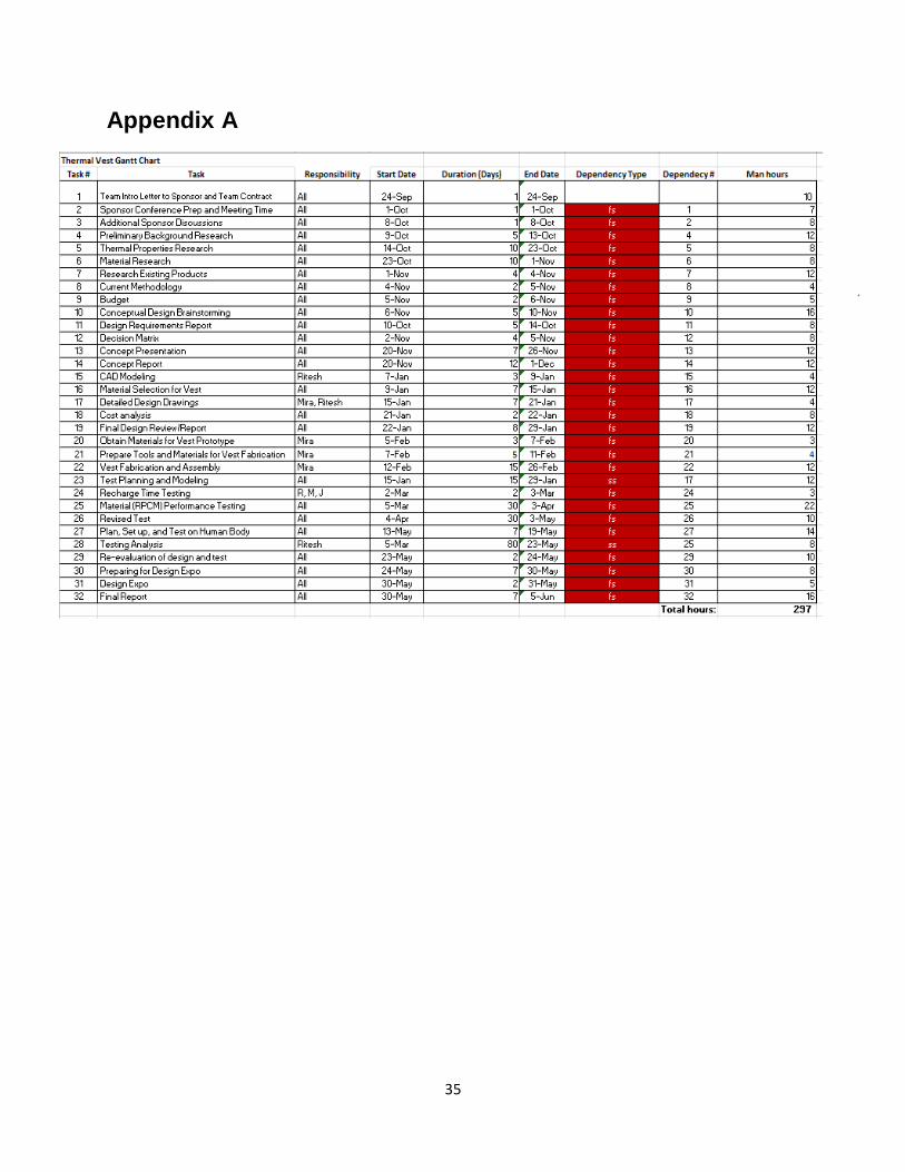
Dr. Richard Savage has been the project advisor and has given much guidance. The rest of the team members have worked throughout the past school year to design, create and test this project. Appendix A shows the work breakdown structure (WBS) giving the total number of man hours to be 297. The estimated hours at the beginning of the project were 650 man hours. This estimate may have been high because it was
7
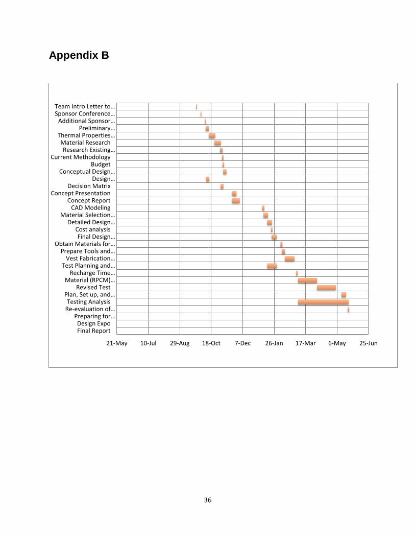
anticipated that certain tasks may take a lot more time than they actually did. Also, the team may have misjudged the amount that it would be capable of doing. The team may have been overly ambitious and thought that more could get done than was actually possible. Appendix B shows the Gannt chart for the past three quarters.
Background
The group has been assigned to design a thermo-regulative vest for QL+. Dr. Richard Savage has provided us with research material describing multiple types of thermoregulation and vests. From this, the team has a solid understanding of the most ideal methods of cooling down the human body. This is the second year that this vest is being worked on where the previous team’s finished product was strictly concepts and models, rather than a tangible prototype. The goal is to build on this and have a functioning prototype by Summer 2013. By utilizing engineering support classes across an interdisciplinary curriculum (i.e. Thermodynamics, Fluid Mechanics, Electric Circuit Theory, Biomaterials, etc.) the team can combine their collective knowledge to make a quality thermal vest focused toward those with spinal nerve injuries. To help in the selection of an ideal cooling vest design, existing products and studies were researched and analyzed.
Existing (Competitive) Products
Today’s thermal vest products include: ice pack cooling, evaporative cooling, phase change, fluid cooling, and air cooling. A detailed description and analysis of each vest product is included below.
Ice-Pack
The ice-pack system usually includes a vest, which holds the ice packs against the body. The ice packs will absorb heat. Some benefits of using an ice-pack system are that it is inexpensive, portable, and rechargeable. Unfortunately there is a high risk of vasoconstriction involved with this method. Vasoconstriction is the constricting of blood vessels due to the extreme cold environment caused by the ice packs. This tricks the body into thinking it is in a cold environment and does not allow it to dissipate heat very well. There is also a long recharge time for the ice packs and they tend to weigh a lot.
Evaporative
Evaporative cooling vests work by being soaked in water. This method is inexpensive, light weight, and portable, but will not work in high humidity environments. It is also susceptible to bacterial growth, mold and mildew, and can cause skin irritation.
8
Phase Change Material (PCM)
Phase change material (PCM) vests work similarly to the ice-pack vest but use PCM packs in place of the ice-packs. Benefits of using this system are that it is portable, can maintain a comfortable temperature, inexpensive, and lightweight.
Fluid (Umbilical)
Fluid cooling uses a system of tubes to circulate chilled water through the vest. This system can be light weight, but needs to be connected to a pump, battery, and water reservoir, making it difficult to move around with. It also has more moving parts which makes it more difficult to maintain.
Air Chilled
The air chilled method is effective at removing heat, but limits mobility due to the necessity of being hooked up to a compressor by an air line. There are also many moving parts which would require maintenance.
Design Requirements/Specifications The aim of this project is to design a light-weight, thermoregulatory vest with temperature controlling mechanisms and thermal sensors to simulate homeostasis for those who are unable to regulate their core body temperature (i.e. quadriplegics, etc).
Customer Requirements
Our customer requirements include a list of proposed needs and specifications that are to be met during the design process.
Thermoregulation (Maintain core temperature of 98⁰F)
Suitable for ultra-lightweight manual wheelchairs (15-25 pounds)
Functional for 4 to 8 hours
Worn under clothing
Sizeable (160-210 pounds)
Less than 15 pound power supply
Thermostat regulation
9
Easy user interface
Durable
Light-weight
Non-insulating
Highly Dexterous
Project Requirements
From these customer needs, a set of project requirements were derived, which include performance goals, functional requirements, and the level of importance of these requirements (Table I).
Table I: Performance Goals
Thermoregulation Can reduce body temperatures up to 110 °F to 98°F (∆TMax=12°F)
Safety Must be safe for all users to use on a daily basis
Light weight Mechanism must be light enough to wear and transport
Non-Insulating Breathable fabric
Long Lasting Must last an average work day
Durability Must be able to withstand drops and external forces
Comfortability User feels little to no added stress from the vest
Reliability Components must be durable and long-lasting
User Friendly User can easily understand and use mechanism
Washable Water resistant
Cost Must be affordable for target customers
Adjustable Fits users of different sizes
Thin and compact design Can be worn under daily clothing
10
These qualitative performance goals were then transformed into quantitative functional goals (Table II).
Table II: Functional Requirements
Thermoregulation Must dissipate roughly 240 kJ per hour
Safety Must be composed of biocompatible material
Light weight Mechanism must be less than 25 pounds. (Vest < 6 pounds)
Non-Insulating Must allow water to dissipate heat
Long Lasting Battery life between 4 to 8 hours
Durability Must be able to withstand 5 ft. drop
Comfortability User feels little to no added stress from the vest
User Friendly Can learn how to operate the device in 3-5 steps of instruction
Washable Can be submerged 10 ft
Cost Must cost roughly $2000 to build and test
Adjustable Fits users from 160 to 210 pounds
Thin and compact design
No more than 1 inch thick at all locations
These functional goals were then prioritized through QFD analysis based on their influence on the vest’s overall purpose. The top four design requirements were determined to be thermoregulation, safety, light-weight, and non-insulating. Below are the four most crucial requirements explained in further detail as well as an explanation of other important requirements.
Thermoregulation: Must dissipate roughly 240 kJ per hour
The main goal of this project is to regulate an individual’s body temperature at 98 degrees. In order to maintain this core temperature, the entire body must expel 240 kJ per hour when doing moderate activities.
11
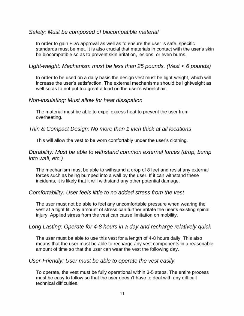
Safety: Must be composed of biocompatible material
In order to gain FDA approval as well as to ensure the user is safe, specific standards must be met. It is also crucial that materials in contact with the user’s skin be biocompatible so as to prevent skin irritation, lesions, or even burns.
Light-weight: Mechanism must be less than 25 pounds. (Vest < 6 pounds)
In order to be used on a daily basis the design vest must be light-weight, which will increase the user’s satisfaction. The external mechanisms should be lightweight as well so as to not put too great a load on the user’s wheelchair.
Non-insulating: Must allow for heat dissipation
The material must be able to expel excess heat to prevent the user from overheating.
Thin & Compact Design: No more than 1 inch thick at all locations
This will allow the vest to be worn comfortably under the user’s clothing.
Durability: Must be able to withstand common external forces (drop, bump into wall, etc.)
The mechanism must be able to withstand a drop of 8 feet and resist any external forces such as being bumped into a wall by the user. If it can withstand these incidents, it is likely that it will withstand any other potential damage.
Comfortability: User feels little to no added stress from the vest
The user must not be able to feel any uncomfortable pressure when wearing the vest at a tight fit. Any amount of stress can further irritate the user’s existing spinal injury. Applied stress from the vest can cause limitation on mobility.
Long Lasting: Operate for 4-8 hours in a day and recharge relatively quick
The user must be able to use this vest for a length of 4-8 hours daily. This also means that the user must be able to recharge any vest components in a reasonable amount of time so that the user can wear the vest the following day.
User-Friendly: User must be able to operate the vest easily
To operate, the vest must be fully operational within 3-5 steps. The entire process must be easy to follow so that the user doesn’t have to deal with any difficult technical difficulties.
12
Adjustability: Various size users can use the vest
Users from 150 pounds to 210 pounds should be able to use the vest with full functionality.
Washable: Must be able to function after being submerged in 5 PSI of water
The vest can be safely washed by the user. For additional safety purposes, the vest can withstand the pressure of being submerged 10 feet into water.
Cost: Must cost less than $2000 to build and test
Building and prototyping the vest must cost no more than $2000. This includes costs for raw materials, pre-manufactured components, testing devices, and/or research materials. Any additional costs may be discussed with QL+.
Design Development
From the requirements specified above as well as research and knowledge of existing solutions, many ideas for a new solution were brainstormed with consideration of the specific user. From these many ideas, the team was able to bring it down to the top three concepts which seemed most feasible by eliminating some ideas due to their inability to satisfy important requirements or other inadequacies. The top three solutions were: an evaporative vest (Figure 1), fluid flow (Figure 2), and a vest utilizing renewable phase change material (RPCM) (Figure 3). A basic idea of pros and cons for each vest as well a basic understanding of how they work has been described above in the Background section of the report. Below is an illustration of each sort of vest as well as a block diagram schematic to help portray their basic concepts.
Figure 1: Evaporative vest picture and accompanying block diagram.
Heat
↓
Outside Air ――> ――> Cool Air
↓
Water Evaporation
Fig.2 Evaporative Cooling
Soaked Thermal Vest
13
This evaporative vest idea would be lightweight, portable, and inexpensive. Unfortunately it would feel damp against the body and possible issues that would have to be dealt with would be mold or mildew. There was also the concern that it wouldn’t work in humid environments which is where our users would probably be.
Figure 2: Fluid flow vest picture and accompanying block diagram.
Fluid flow vest is great when considering the time requirement for cooling, but as seen in the picture above, it needs to be attached to a reservoir which limits the user and their mobility.
Figure 3: RPCM vest with accompanying block diagram.
RPCM can cool the body at a safe temperature. Safety is a very important requirement and this vest seems to be best in that area. The time the RPCM can cool for is a little under the requirement, but a solution was derived which is discussed below.
Energy Input
↓
Work in a cycle ――> ――> Energy output
Fig.1 Water Reservoir System Block Diagram
Fluid Flow
System
Body Heat ――> ――> absorbed heat
↓
Evaporated water
Fig.3 Phase Changing Cold Pack Block Diagram
PCM Pack
14
The pros and cons of each system were discussed and thought about. How each system could be manipulated to best suit the user and fulfill the requirements was also discussed. From these three designs, as well as by utilizing a decision matrix, the conclusion was made that RPCM far exceeded the other options (Appendix C). After looking through all the vest types, it has become very clear that RPCM vests have the most strengths and the least amount of weakness when being compared to the fluid chilled system as the datum. In order for this to be a successful model/prototype the criteria that needs to be improved on are “long lasting” by increasing its cooling duration and the “thin and compact design” by making the vest less bulky for the user.
Final Design Concept
Description of Final Design
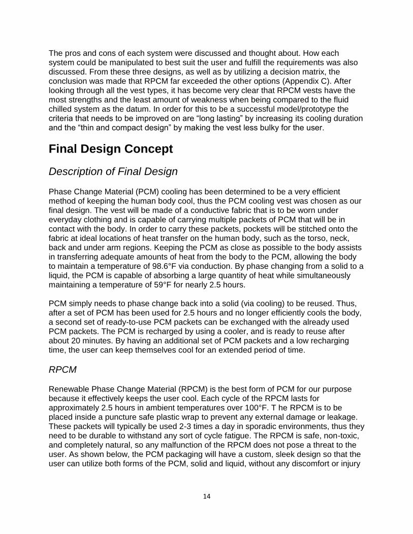
Phase Change Material (PCM) cooling has been determined to be a very efficient method of keeping the human body cool, thus the PCM cooling vest was chosen as our final design. The vest will be made of a conductive fabric that is to be worn under everyday clothing and is capable of carrying multiple packets of PCM that will be in contact with the body. In order to carry these packets, pockets will be stitched onto the fabric at ideal locations of heat transfer on the human body, such as the torso, neck, back and under arm regions. Keeping the PCM as close as possible to the body assists in transferring adequate amounts of heat from the body to the PCM, allowing the body to maintain a temperature of 98.6°F via conduction. By phase changing from a solid to a liquid, the PCM is capable of absorbing a large quantity of heat while simultaneously maintaining a temperature of 59°F for nearly 2.5 hours.
PCM simply needs to phase change back into a solid (via cooling) to be reused. Thus, after a set of PCM has been used for 2.5 hours and no longer efficiently cools the body, a second set of ready-to-use PCM packets can be exchanged with the already used PCM packets. The PCM is recharged by using a cooler, and is ready to reuse after about 20 minutes. By having an additional set of PCM packets and a low recharging time, the user can keep themselves cool for an extended period of time.
RPCM
Renewable Phase Change Material (RPCM) is the best form of PCM for our purpose because it effectively keeps the user cool. Each cycle of the RPCM lasts for approximately 2.5 hours in ambient temperatures over 100°F. T he RPCM is to be placed inside a puncture safe plastic wrap to prevent any external damage or leakage. These packets will typically be used 2-3 times a day in sporadic environments, thus they need to be durable to withstand any sort of cycle fatigue. The RPCM is safe, non-toxic, and completely natural, so any malfunction of the RPCM does not pose a threat to the user. As shown below, the PCM packaging will have a custom, sleek design so that the user can utilize both forms of the PCM, solid and liquid, without any discomfort or injury
15
aggravation. Actual packets of the RPCM from Glacier Tek, Inc. have been obtained and are shown below. (Figure 4).
Figure 4: RPCM Packets
Final Design of Vest
A final design for the vest which will carry the RPCM packets had been decided upon (Figure 5). Dimensions of the vest are detailed out in Appendix D.
16
Figure 5: Vest design
The main fabric for the vest was made of a polyester cotton blend. This lightweight fabric possesses many of the requirements specified above for the vest. It is durable, strong, and breathable. It is also much more easily sewn than cotton on its own. The pouches which will be sewn on the inside of the vest will be carrying the RPCM packets. They are made of a mesh which will allow for the maximum amount of heat transfer from the body to the RPCM. The mesh will not insulate the body from the RPCM. The pouches are placed in a way that they will cover the core of the body, which is where most of the heat is stored. Elastic straps will hold the front and back sides of the vest together. They are used as both top and side straps. An advantage of using elastic is that it allows for multiple sized people to use the vest. It will also allow the user to wear the vest more snugly and comfortably. This snug fit will provide a good thermal contact and therefore cool the body better. These elastic straps will be held down by Velcro. The Velcro was chosen as the best method for attachment due to its flexibility. It does not cause any unnecessary stress or discomfort. There is also a zipper down the front middle of the vest. This accommodates many different users. It is a way for size to be set once and kept there. It also enables a user who may need help putting on the vest to have different options of which works better for them or whoever is assisting them.
Cooler
A major drawback of the PCM is that each cycle lasts for approximately 2.5 hours, while the minimum daily required time to cool the body is 4 hours. Therefore, the PCM must be recharged after a cycle in order to reuse the PCM. This requirement can be fulfilled by using a portable cooler with ice water to extract the stored heat in the PCM and
17
phase change the PCM from a liquid back to a solid (Figure 6). In addition, spare PCM packets can be placed in the cooler so that the user will not experience any delay time when the first set of PCM has exhausted. Any cooler can be used to suite the user’s needs. They can buy any already manufactured cooler at a store and choose what size is best for them. This way the user can essentially run as many cycles as it takes to stay cool throughout the entire day.
Figure 6: Cooler to recharge and carry spare RPCM packets.
Manufacturing & Cost
All these components for creating the vest are readily available. They were obtained from Beverley’s (a local fabric and craft supplies store). After the materials were obtained, the process of creating the vest began. This process included creating a pattern, cutting out the fabric and other materials to the correct size, pinning them together, and then using a sewing machine to sew them. Figures 7 and 8 show the final prototype after it was completely assembled.
18
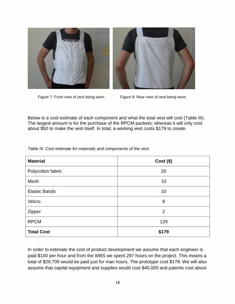
Figure 7: Front view of vest being worn. Figure 8: Rear view of vest being worn.
Below is a cost estimate of each component and what the total vest will cost (Table III). The largest amount is for the purchase of the RPCM packets; whereas it will only cost about $50 to make the vest itself. In total, a working vest costs $179 to create.
Table III: Cost estimate for materials and components of the vest
Material Cost ($)
Polycotton fabric 20
Mesh 10
Elastic Bands 10
Velcro 8
Zipper 2
RPCM 129
Total Cost $179
In order to estimate the cost of product development we assume that each engineer is
paid $100 per hour and from the WBS we spent 297 hours on the project. This means a
total of $29,700 would be paid just for man hours. The prototype cost $179. We will also
assume that capital equipment and supplies would cost $40,000 and patents cost about
19
$100,000. This means we can assume this project would have cost about $169,897 to
develop.
The vest took about 12 hours to create. In order to analyze the actual price to
manufacture a vest, it is assumed that a rate of $75 per hour is the cost to pay someone
to make the vest, and therefore it would cost $1079 to make each vest. This is
assuming that tooling, such as the sewing machine, was already available. The number
of hours however could be greatly reduced after experience is gained in creating a vest
and fewer steps were necessary for completion.
Design Verification Plan/Testing
A series of tests were conducted to assure that the proposed design of the temperature
regulating cooling vest met the customer requirements. Multiple iterations of the
following three main tests were conducted to quantify the premise of our proposed
design:
1. RPCM Latent Heat of Fusion Test (Test #1)
2. RPCM Insulated Environment Test (Test #2)
3. RPCM Human Simulation Test (Test #3)
4. RPCM Recharge Test (Test #4)
Test #1: RPCM Latent Heat of Fusion Test
Test Background
Test #1 was conducted to determine the properties of the RPCM that are being used to
cool the body down. No critical physical or chemical details were known about the
RPCM prior to our testing, besides that the RPCM has a phase change (from solid to
liquid) temperature of 59°F. Therefore, this test was done to determine the RPCM’s
potential of safely and effectively keeping the body cool. The results from the test setup
allowed us determine the following:
The amount of heat capable of being storage by the RPCM.
The time it would take for the RPCM to completely melt.
Accuracy of the manufacturer’s claim of the temperature at which the RPCM
changes phase.
Test Setup
20
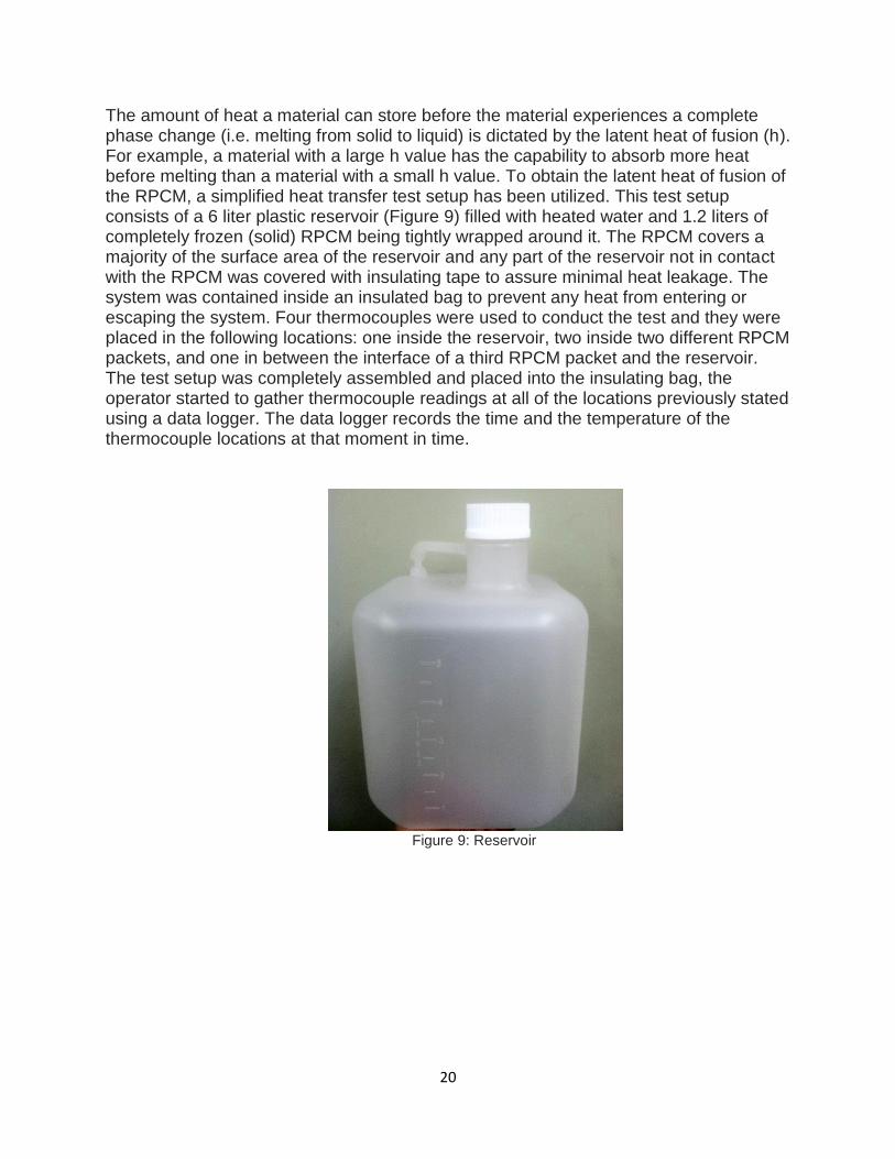
The amount of heat a material can store before the material experiences a complete phase change (i.e. melting from solid to liquid) is dictated by the latent heat of fusion (h). For example, a material with a large h value has the capability to absorb more heat before melting than a material with a small h value. To obtain the latent heat of fusion of the RPCM, a simplified heat transfer test setup has been utilized. This test setup consists of a 6 liter plastic reservoir (Figure 9) filled with heated water and 1.2 liters of completely frozen (solid) RPCM being tightly wrapped around it. The RPCM covers a majority of the surface area of the reservoir and any part of the reservoir not in contact with the RPCM was covered with insulating tape to assure minimal heat leakage. The system was contained inside an insulated bag to prevent any heat from entering or escaping the system. Four thermocouples were used to conduct the test and they were placed in the following locations: one inside the reservoir, two inside two different RPCM packets, and one in between the interface of a third RPCM packet and the reservoir. The test setup was completely assembled and placed into the insulating bag, the operator started to gather thermocouple readings at all of the locations previously stated using a data logger. The data logger records the time and the temperature of the thermocouple locations at that moment in time.
Figure 9: Reservoir
21
Figure 10: Test #1 Test Setup Outside of Insulated Bag
Figure 11: Completely Melted RPCM Packet with Thermocouple Inserted
22
Test Parameters, Results, and Discussion To simplify the calculations from the results, it is assumed that all the heat
dissipated from the water in the reservoir is absorbed by the RPCM. The test data from the thermocouple is logged starting the moment the test setup is completed, but this does not necessarily mean that the RPCM is changing phase. This is because the RPCM starts phase changing at 59°F, and the RPCM is not at 59°F when the test setup is completely assembled. Rather, the RPCM is only warming up and on its way to reach 59°F to begin a phase change and thus this data is not considered when the RPCM latent heat of fusion is calculated.
Data gathered from the thermocouples was analyzed and plotted to determine
the different properties of the RPCM. Analyzing the data was done using governing equations of heat transfer which ultimately gave us the properties and performance results of the RPCM. The following tables include givens parameters and variables used in our analysis. Following the tables is the list of governing equations that were used to determine the RPCM properties and performance results.
Table IV: Known Constant Parameters
Description Symbol Value
Specific Heat of Water pc 4.184 kJ/kg·°C
Mass of water in reservoir OHm
2 6 kg
Rate of human body heat dissipation by
in region covered by vest
bodyQ
68 watts
Volume of RPCM in Vest RPCMV 2.4 liters
Table V: Variable Parameters
Description Symbol Units
Heat Released from Water Reservoir releasedQ kJ
Change in Temperature of
Water in Reservoir OHT
2 °C
Latent Heat of Fusion of RPCM
h kJ/kg
Heat Released from Body into Vest vestQ kJ
Volume of RPCM Melted in Tests meltV liters
23
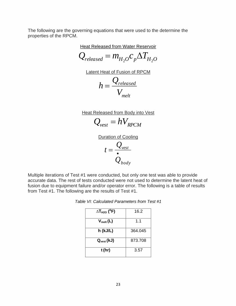
The following are the governing equations that were used to the determine the properties of the RPCM.
Heat Released from Water Reservoir
OHpOHreleased TcmQ22
Latent Heat of Fusion of RPCM
melt
released
V
Qh
Heat Released from Body into Vest
RPCMvest hVQ
Duration of Cooling
body
vest
Q
Qt
Multiple iterations of Test #1 were conducted, but only one test was able to provide accurate data. The rest of tests conducted were not used to determine the latent heat of fusion due to equipment failure and/or operator error. The following is a table of results from Test #1. The following are the results of Test #1.
Table VI: Calculated Parameters from Test #1
∆TH2O (⁰F) 16.2
Vmelt (L) 1.1
h (kJ/L) 364.045
Qvest (kJ) 873.708
t (hr) 3.57
24
Figure 12: Graph of Sample Data from Test #1 showing thermocouple temperature inside two RPCM packets vs. time.
As seen in the results from Table VI, 2.4 liters of the RPCM is capable of absorbing 873 kJ, which would last for roughly 3.5 hours if it were used to cool the body down with direct contact. Figure # above shows the trend of the temperature of the RPCM throughout the test. Both the curves have an initial temperature below 59°F and thus there’s a period of time in which the RPCM warms up to 59°F before changing phase from a solid to a liquid. Even though heat is being absorbed by the RPCM during this period of time, it has not been factored into the time of cooling, t. This is because the initial temperatures of the RPCM vary for each test and this does not give consistent time of cooling data. The RPCM then reaches 59°F and begins to isothermally phase change from a solid to a liquid, as seen in the somewhat horizontal portion of the curve from ~2000 seconds to ~5250 seconds. The thermocouples do not detect an isothermal phase change at 59°F because the core of the RPCM and the melted liquid closest to the interface of the RPCM and reservoir that has already melted slightly vary in temperature. Thus, this slightly skews the data, but it can be seen that phase change is taking place around these temperatures. Different packets of RPCM at different locations of the reservoir melt at varying rates. Ideally, this is not supposed to happen. However, there are many variables (different contact pressure between each of the RPCM packets and the reservoir, different initial temperatures, unequal volumes of RPCM in each packet, etc.) that cannot be avoided while running the experiment. To account for this, whenever the first packet of RPCM
completely melted, we would call an end of the experiment and accurately estimate the volume of RPCM melted, Vmelt, in the remaining packets. This incident is seen in the graph above. The red curve represents the RPCM packet that has completely changed phase at ~5250 seconds and then rapidly increases in temperature while the blue curve represents the RPCM at phase change temperature and continues to change phase past the 5250 second mark. The data used for this test came from between ~2000 seconds and ~5250 seconds and were scaled to represent 2.4 liters of RPCM changing phase on the vest. This ultimately yielded Qvest of 873.708 kJ and t of 3.57 hours listed in Table #.
Test #2: RPCM Insulated Environment Test Test Background Test #2, the RPCM Insulated Environment Test, was conducted to simulate the process of a human body wearing a vest loaded with RPCM. To do this, fabric is simply added into the test setup. Other than that, the rest of Test #2 is exactly the same as Test #1. Therefore, the parameters gathered from Test #2 can be compared to the control group parameters gathered in Test #1 to determine if the layers of fabric made a sizeable difference in the time of cooling, t. Test Setup Test #1 and Test #2 are setup up almost identically. The difference, however, is that the water reservoir used in Test #2 is completely wrapped in mesh fabric. The RPCM is then wrapped firmly around this mesh, and a solid fabric layer is wrapped around the RPCM. This test setup is then placed into the insulating bag. All the other test setup details remain the same. The purpose for this is to simulate the RPCM being placed in the vest and determining the effects of having fabric completely surround the RPCM during phase change.
Figure 13: Completely Frozen RPCM Packet with Thermocouple Inserted
26
Figure 14: Test Setup of Test #2 Outside of Insulated Bag
Figure 15: Test Setup Inside of Insulated Bag
27
Figure 16: Partially Melted RPCM Packet with Thermocouple Inserted
Test Parameters, Results, and Discussion
The same test assumptions made in Test #1 exist in Test #2. Three different trails of Test #2 were conducted and the results of each test are listed in the tables below.
Table VII: Calculated Parameters from Test #2, Trial 1
Trial 1 Trial 2 Trial 3
∆TH2O (⁰F) 10.7 15 15.11
Vmelt (L) 0.65 1.1 0.95
h (kJ/L) 409.234 356.844 400.41
Qvest (kJ) 982.167 856.426 960.986
t (hr) 4.01 3.5 3.93
28
Figure 17: Graph of Sample Data from Test #2 showing thermocouple temperature inside two RPCM packets vs. time
The data gathered from Test #2 are fairly consistent in regards to each trial. The latent
heat of fusion, h, and heat absorbed by the vest, Qvest, in Trial 1 and Trial 3 are very
similar compared to Trial 2. This is very likely a result of the different variables that are
mentioned in the Test Parameters, Results and Discussion section of Test #1. The
prediction was that the RPCM would last for a shorter time when it is wrapped in fabric
because the fabric causes a seal and essentially transfers more heat to the RPCM and
less to the environment. This is clearly not the case because the RPCM is predicted to
last ~ 4 hours according to Trial 1 and Trial 3. A possible explanation for this could be
that the thermocouple in the RPCM packets may have had more exposure to the RPCM
solid core, which stays at a constant 59°F, than that of Trial 2 and Test #1. Therefore,
the illusion that the RPCM performed better in Trial 1 and Trial 3 exists. Nevertheless,
Qvest and h are fairly similar in Test #1 and Test #2 and it is safe to say that the RPCM
can cool the body for longer than 3 hours at a time.
Test #3: RPCM Human Simulation Test
Test Description Test #1 and Test #2 provided reliable data on the RPCM’s performance on a stagnant reservoir of water. The human body, however, is very different than a stagnant reservoir of water for the following reasons:
The body dissipates heat while generating heat at the same time.
The body reacts to the cold RPCM packet by changing its rate of heat dissipation.
The temperature between the interface of the body and RPCM is very unsteady
There is a temperature gradient between the surface and the core of the body (i.e. the body is not at a uniform temperature.)
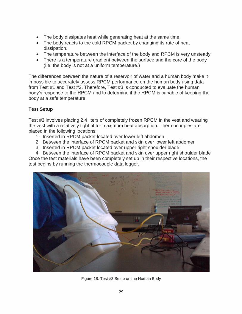
The differences between the nature of a reservoir of water and a human body make it impossible to accurately assess RPCM performance on the human body using data from Test #1 and Test #2. Therefore, Test #3 is conducted to evaluate the human body’s response to the RPCM and to determine if the RPCM is capable of keeping the body at a safe temperature. Test Setup Test #3 involves placing 2.4 liters of completely frozen RPCM in the vest and wearing the vest with a relatively tight fit for maximum heat absorption. Thermocouples are placed in the following locations:
1. Inserted in RPCM packet located over lower left abdomen 2. Between the interface of RPCM packet and skin over lower left abdomen 3. Inserted in RPCM packet located over upper right shoulder blade 4. Between the interface of RPCM packet and skin over upper right shoulder blade
Once the test materials have been completely set up in their respective locations, the test begins by running the thermocouple data logger.
Figure 18: Test #3 Setup on the Human Body
30
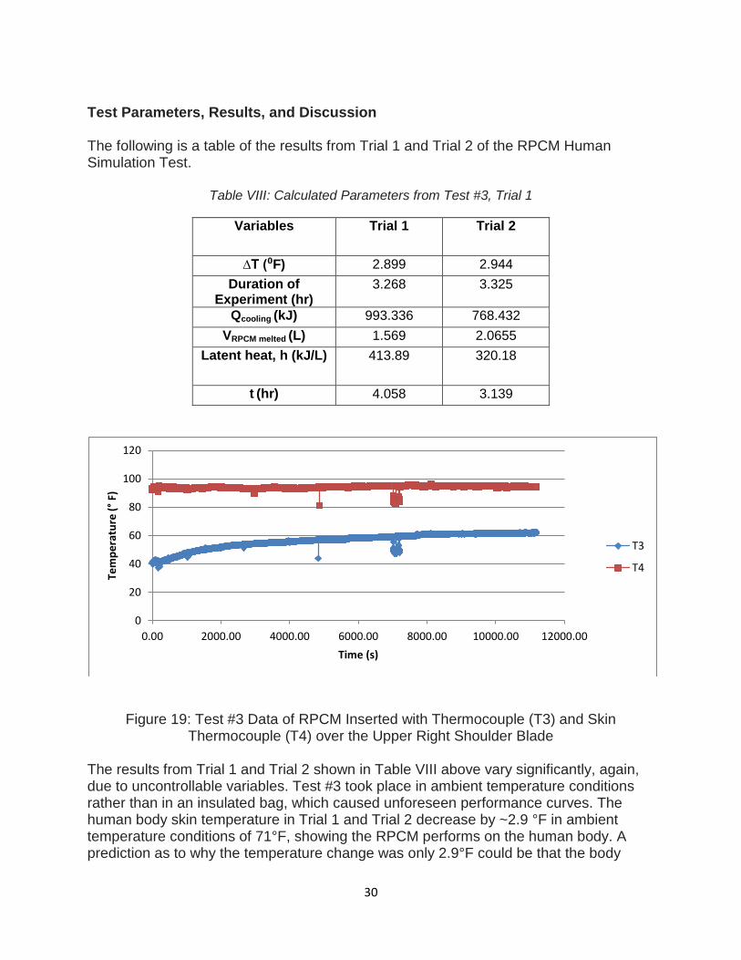
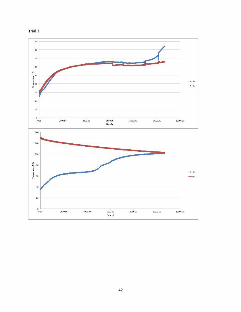
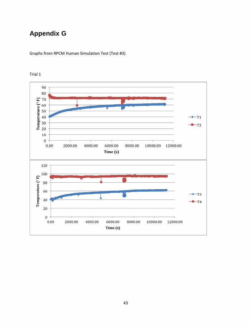
Test Parameters, Results, and Discussion The following is a table of the results from Trial 1 and Trial 2 of the RPCM Human Simulation Test.
Table VIII: Calculated Parameters from Test #3, Trial 1
Figure 19: Test #3 Data of RPCM Inserted with Thermocouple (T3) and Skin Thermocouple (T4) over the Upper Right Shoulder Blade
The results from Trial 1 and Trial 2 shown in Table VIII above vary significantly, again, due to uncontrollable variables. Test #3 took place in ambient temperature conditions rather than in an insulated bag, which caused unforeseen performance curves. The human body skin temperature in Trial 1 and Trial 2 decrease by ~2.9 °F in ambient temperature conditions of 71°F, showing the RPCM performs on the human body. A prediction as to why the temperature change was only 2.9°F could be that the body
dampened its rate of heat released. By reducing the rate of heat released, the body can counter the effects of the RPCM from reducing the core body temperature below the optimal temperature of 98.6°F, which the RPCM was clearly doing by being used in fairly cool temperature. If the vest had been tested in higher ambient temperatures, it is the RPCM would be cooling a body at an elevated internal temperature. Thus, the change in body temperature after using the RPCM vest would be larger than that seen in Trial 1 and Trial 2 of Test #3. The RPCM did not completely melt in the 3.25 hours allotted to run the RPCM test before the data logger ran out of memory. Aside from the body dampening its rate of heat dissipated, the environment did not transfer much heat into the RPCM packets. A hot, humid, and sunny environment would transfer more heat into the RPCM than that of the testing environment. This would result in a fast RPCM melting rate because there would be multiple sources of heat rather than just the body. Therefore, the RPCM would not last as long as it did in Trial 1 and Trial 2. Again, it is very difficult to accurately remark on how the body reacts to the RPCM cooling it down because there is insufficient data. The cooling of a water reservoir is a linear process while cooling of a human body is a multi-order cooling curve that cannot be analyzed with the basic equipment used to conduct Test #3. However, a similar trend is seen in Trial 1 and Trial 2, so it is safe to say that the RPCM has the capability of effectively cooling the human body.
Test #4: RPCM Recharge Test
Test Description
Testing to determine the fastest and most efficient method to recharge the RPCM (from liquid to solid) is very important. The reason being that the RPCM could easily melt in less than 3 hours when it is used in very hot environments, putting the user at risk if they he/she is not continued to be cooled down. Two methods of cooling the RPCM were tested: cooling the RPCM in the freezer and cooling the RPCM in an ice bath. Although it’s not practical for a wheelchair user to lug around a freezer, testing the RPCM in a freezer gave data to compare the results of different tests to. Thus, Test #4 determines the fastest and most feasible method of recharging the RPCM while the user is on-the-go in hot weather.
Test Setup
The test setup consisted of an ice chest filled with ice and water at ~40°F and freezer of a mini-fridge operating at ~40°F. A packet of completely melted RPCM at room temperature was placed into the both the ice chest and the freezer. Right after, a stop watch was used to record the time it took to completely freeze the RPCM in each of the cooling mediums.
32
Test Parameters, Results, and Discussion It took the RPCM ~23 minutes to completely phase change from solid to liquid in the ice chest and ~60 minutes in the freezer. Liquid water’s superior ability to conduct/absorb heat comes from its density and physical properties. Air in the freezer, on the other hand, is very light and not as effective at storing heat. Therefore, the ice bath is the best method of cooling the RPCM rapidly. The wheelchair can be easily retrofitted with a storage device, like the insulated bag like the one used in Test #1 and Test #2, to store cold water to recharge the RPCM. Simply taking out the melted RPCM out of the vest, submerging it into the ice bath, allowing it change phase from a liquid to a solid, and putting it back into the vest allows the user to stay cooling for long periods of time in hot temperature environments.
Specification Verification All the requirements for the vest have been met. In Table IX below, it is shown that each of the requirements has been met by analysis (A), testing (T), similarity to existing designs (S), or inspection (I).
Table IX: Requirements and method of verification.
Requirement Specification Verification Method
Thermoregulation Must dissipate roughly 240 kJ per hour
A
Safety Must be composed of biocompatible material
I, S
Light weight Mechanism must be less than 25 pounds. (Vest < 6 pounds)
I
Non-Insulating Must allow water to dissipate heat S
Long Lasting Life between 4 to 8 hours T, A
Durability Must be able to withstand 5 ft. drop S
Comfortability User feels little to no added stress from the vest
T, S
User Friendly Can learn how to operate the device in 3-5 steps of instruction
I
Washable Can be submerged 10 ft S
Cost Must cost roughly $2000 to build and test
A
Adjustable Fits users from 160 to 210 pounds I
Thin and compact design
No more than 1 inch thick at all locations
I
33
By inspecting the vest, it was determined that it was safe, lightweight, user friendly, adjustable, and had a thin and compact design. The weight was measured to be 5 pounds with all four packs of RPCM in the pockets of the vest which is below the 6 pound limit. The vest is 1 inch thick with all packets in the pouches. It is known that the RPCM is safe and the vest is composed of fabric which is also safe. It is known to be adjustable due to the elastic straps included in the vest design. Through analysis of test data, the requirement for thermoregulation has been met. Each RPCM pouch was determined to last about 3 hours, but the vest can be used indefinitely with spare packs available and a low recharge time for the RPCM. The vest created cost less than $200 which was far below the maximum limit. The vest is made of a polyester cotton blend which is known to be washable, comfortable, durable, and safe.
Conclusions/Recommendations The RPCM latent heat of fusion test, insulated environment test, and the human simulation test show that the vest design can essentially thermoregulate a person for about 3.5 hours before needing to be recharged. This cooling time was estimated based on the RPCM’s calculate latent heat of fusion of about 380 kJ/L. From these results, the tests prove the vest design to agree with customer needs as well as the engineering specifications. Some limitations in the model include the simplicity of the design—the human body is a very complex heat exchanger and with limited resources is hard to simulate. In addition, the user focus is thermally intolerant—meaning in order to get a more accurate grasp of how our design performs the test subject must have a thermal intolerance as well. Overall the design performed as desired and with future work in mind the vest could become a very useful device for not only those with spinal injuries but also people that need to cool off, whether it be from exercise or a hot environment.
34
References
Schmidt KD, Chan CW. Thermoregulation and fever in normal persons and in those with spinal cord injuries. Mayo Clinic Proc. 1992 May;67(5):469-75. Review. PubMed PMID: 1405774.
Staff, Mayo Clinic. "Heat Stroke - MayoClinic.com." Mayo Clinic. Mayo Clinic. <http://www.mayoclinic.com/health/heat-stroke/DS01025>.
"Cooling Vest." Ms Cooling - Body Cooling Devices and Other Personal Cooling Products. MS Cooling Climate Control Products. <http://www.mscooling.com/faq>.
"Pro-Kold - Kold Vest and Ice Wrap Products." Pro-Kold Reusable Ice Wraps. Dura*Kold, 2011. <http://www.pro-kold.com/dkkvest.htm>.
"Gear Guide: Cooling Vests & Apparel." ActiveMSers: Staying Active With Multiple Sclerosis. ActiveMSers: Staying Active With Multiple Sclerosis. <http://www.activemsers.org/tipstricks/choosingacoolingvest.html>.
"TST Sweden AB Body Temperature Control Vest "Cooling Vest"" GADELIUS. GADELIUS. <http://www.gadelius.com/products/other_disaster_relief_equipment/05_e.htmlment/05_e.html>.
"Circulating Cold Water Cooling Vest System for People with MS,surgeons, Race Car Drivers, Truck Drivers and Many Other Applications." PolarProducts.com Polar Products Body Cooling Vests. Polar Products Inc. Web. 31 Oct. 2011. <http://www.polarsoftice.com/softiceactivevest.html>.
"Body Cooling Systems." Welcome to Air Systems International, Inc. On-Line Catalog. Air Systems International, Inc. <http://www.airsystems.cc/product_pages/environmental_control/body_cooling_systems.htm>.