Datasheet Continuously monitor machine health, run time, and detect unexpected machine failures such as early bearing failure, unbalance, misalignment, etc. with the Sure Cross Vibration and Temperature QM30VT2 Sensor. The QM30VT2 works in a variety of machines to identify and predict failures in rotating machinery. Paired with a Sure Cross wireless Node, the QM30VT2 becomes the ultimate predictive maintenance tool for wireless vibration and temperature monitoring. • Detects dual-axis vibration up to 4 kHz bandwidth • Output actionable data such as RMS Velocity, RMS High Frequency Acceleration, Peak Velocity, etc. which is pre-processed from the vibration waveforms in the sensor • Provides high accuracy vibration and temperature measurements • Industrial grade sensor with small form factor to fit in the tightest locations • Manufactured with stainless steel or aluminum housing, depending on the model • Connects to a MultiHop Modbus radio or any Modbus network for easy set up and installation, even in the hardest to reach and rugged locations • Functions as a Modbus slave device via RS-485 WARNING: • Do not use this device for personnel protection • Using this device for personnel protection could result in serious injury or death. • This device does not include the self-checking redundant circuitry necessary to allow its use in personnel safety applications. A device failure or malfunction can cause either an energized (on) or de- energized (off) output condition. For additional information, updated documentation, and a list of accessories, refer to Banner Engineering's website, www.bannerengineering.com. Models Model Housing Type Connections and Cable I/O QM30VT2-SS-9M 316L Stainless Steel 9.1 m (30 ft) Flying Leads Vibration and temperature via RS-485 Modbus QM30VT2 Aluminum 2.09 m (6.85 ft) cable with a 5-pin M12/Euro-style male quick disconnect (QD) The Sensor Configuration Software offers an easy way to manage sensor parameters, retrieve data, and visually show sensor data from a number of different sensors. The Sensor Configuration Software runs on any Windows machine and uses an adapter cable to connect the sensor to your computer. Download the most recent version of the software from Banner Engineering's website: www.bannerengineering.com and select Software from the Products drop-down list. Configure this sensor using the Sensor Configuration Software (instruction manual p/n 170002) and USB to RS-485 adapter cable model BWA-UCT-900 (datasheet p/n 140377). When updating the firmware, you must use one of the two USB to RS-485 adapter cables plus a splitter pigtail cable p/n 83265. . Installation Instructions Connecting the Vibration/Temperature Sensor To install the sensor to a device with a 5-pin M12/Euro-style female connector: 1. Align the notch in the female connector with the key in the sensor’s male connector. 2. Gently slide the sensor end into the connector. 3. Rotate the threaded nut to tighten the sensor down. Wiring This sensor is designed for use as a Modbus slave. This sensor can be plugged into any Modbus RS-485 network, including compatible MultiHop Data Radios. Sure Cross ® QM30VT2 Vibration and Temperature Sensor Original Document 210732 Rev. B 14 August 2019 210732
Transcript
DatasheetContinuously monitor machine health, run time, and detect unexpected machine failures such as early bearing failure, unbalance,misalignment, etc. with the Sure Cross Vibration and Temperature QM30VT2 Sensor. The QM30VT2 works in a variety of machinesto identify and predict failures in rotating machinery. Paired with a Sure Cross wireless Node, the QM30VT2 becomes the ultimatepredictive maintenance tool for wireless vibration and temperature monitoring.
• Detects dual-axis vibration up to 4 kHz bandwidth• Output actionable data such as RMS Velocity, RMS High Frequency
Acceleration, Peak Velocity, etc. which is pre-processed from the vibrationwaveforms in the sensor
• Provides high accuracy vibration and temperature measurements• Industrial grade sensor with small form factor to fit in the tightest locations• Manufactured with stainless steel or aluminum housing, depending on the
model• Connects to a MultiHop Modbus radio or any Modbus network for easy set up
and installation, even in the hardest to reach and rugged locations• Functions as a Modbus slave device via RS-485
WARNING:• Do not use this device for personnel protection• Using this device for personnel protection could result in serious injury or death.• This device does not include the self-checking redundant circuitry necessary to allow its use in
personnel safety applications. A device failure or malfunction can cause either an energized (on) or de-energized (off) output condition.
For additional information, updated documentation, and a list of accessories, refer to Banner Engineering's website, www.bannerengineering.com.
Models
Model Housing Type Connections and Cable I/O
QM30VT2-SS-9M 316L Stainless Steel 9.1 m (30 ft) Flying Leads Vibration and temperature viaRS-485 ModbusQM30VT2 Aluminum 2.09 m (6.85 ft) cable with a 5-pin M12/Euro-style male quick disconnect (QD)
The Sensor Configuration Software offers an easy way to manage sensor parameters, retrieve data, and visually show sensor datafrom a number of different sensors. The Sensor Configuration Software runs on any Windows machine and uses an adapter cableto connect the sensor to your computer. Download the most recent version of the software from Banner Engineering's website: www.bannerengineering.com and select Software from the Products drop-down list.
Configure this sensor using the Sensor Configuration Software (instruction manual p/n 170002) and USB to RS-485 adapter cablemodel BWA-UCT-900 (datasheet p/n 140377). When updating the firmware, you must use one of the two USB to RS-485 adaptercables plus a splitter pigtail cable p/n 83265. .
Installation Instructions
Connecting the Vibration/Temperature SensorTo install the sensor to a device with a 5-pin M12/Euro-style female connector:
1. Align the notch in the female connector with the key in the sensor’s male connector.2. Gently slide the sensor end into the connector.3. Rotate the threaded nut to tighten the sensor down.
WiringThis sensor is designed for use as a Modbus slave. This sensor can be plugged into any Modbus RS-485 network, includingcompatible MultiHop Data Radios.
5 gray (gy)Not Used (default) or Discrete NPN Select Line (optional). When updating the firmware, you mustground pin 5 by connecting it to pin 3.
Installing the Sensor
The vibration sensors have an X and Z axis indication on the face of the sensor. The Z axisgoes in a plane through the sensor while the X is parallel to the sensor.
• Install the X axis in line with the shaft of the motor or axially.• Install the Z axis to go into or through the motor or radial.
For the best results, install the sensor as close to the motor bearing as possible. If this isnot possible, install the sensor on a surface that is in rigid connection with vibrationcharacteristics of the motor. Using a cover shroud or other flexible mounting location mayresult in reduced accuracy or reduced ability to detect certain vibration characteristics.
X-axis VibrationSensitivity
Z-axis VibrationSensitivity
After determining the sensor direction and location, mount the sensor for the best possible vibration sensing accuracy.
Mounting Options Applicable QM Models Description
BWA-BK-014 QM30VT1, QM30VT2 Flat bracket with direct screw mount to motor and sensor
When available, directly mounting the bracket to the motor using an M4 × 0.7 bolt provides a rigidsurface with the highest sensor accuracy and frequency response. This mounting option offersflexibility for future sensor and bracket movement.
BWA-BK-012 QM30VT2-SS-9M
BWA-BK-014 QM30VT1, QM30VT2 Flat bracket epoxied to motor and sensor screwed to bracket
Recommend using an epoxy designed for accelerometer mounting, such as Loctite Depend 330 and7388 activator.
Epoxying a bracket to a motor provides a permanent installation of the bracket to which the sensorcan be attached. This more rigid mounting solution ensures some of the best sensor accuracy andfrequency response, but is not flexible for future adjustments.
BWA-BK-012 QM30VT2-SS-9M
BWA-BK-013QM30VT1, QM30VT2,QM30VT2-SS-9M
Flat magnet bracket
Gives a solid, strong, and adjustable mount to a motor, but with a motor's curved surface it may notprovide the best connection if the motor is too small for the magnet to get a full connection with themotor housing.
Magnet mounts are susceptible to accidently rotation or change in sensor location if an outside forcebumps or moves the sensor. This can lead to a change in sensor information that differs from thetime-trended data from the previous location.
Thermally ConductiveAdhesive tape
QM30VT1, QM30VT2,QM30VT2-SS-9M
Often provides a more than sufficient mounting type but does introduce some additional flex thatreduces accuracy
Holding RegistersBy default, data is sampled every five seconds. Use the Sensor Configuration Tool to adjust the sensor's sample rate if a differentvalue is needed. Aliased register addresses are user configurable. Aliased addressed registers are sequenced to be read with onesingle Modbus read. Temperature values outside of the operating range of the device are forced to the maximum or minimumvalues.
Modbus RegisterAlias Address
Modbus RegisterAddress
DescriptionI/O Range Holding Register Representation
46103 Modbus Slave Address 1 (default) through 247
42601Rotational Speed (RPM) (default = 1725 RPM) --Used in vibration spectral band measurements
0 65535 0 65535
42602Rotational Speed (Hz) (default = 29 Hz) -- Used invibration spectral band measurements
0 65535 0 65535
1 Value = Register value ÷ 100002 Value = Register value ÷ 10003 Value = Register value ÷ 100
4 Value = Register value ÷ 105 Measurement bandwidth = 10 Hz to 1 kHz6 Measurement bandwidth = 1 kHz to 4 kHz
Vibration Spectral Band MeasurementsTo use vibration spectral band measurements, follow the instructions in the Vibration Spectral Band Measurement Start Guide (p/n b_4510565).
Specifications
Supply Voltage10 to 30 V dc
CurrentActive comms: 9 mA at 30 V dc
CommunicationInterface: RS-485 serialBaud rates: 9.6k, 19.2k (default), or 38.4kData format: 8 data bits, no parity (default), 1 stop bit (even or odd parityavailable)Protocol: Modbus RTU
Vibration SensorMeasuring Range: 0 to 46 mm/sec or 0 to 1.8 in/sec RMSFrequency Range: 10 Hz to 4 kHzAccuracy: ±10% at 25 °CSampling Frequency: 20 kHz (default)Record Length: 8192 points (default)Sample Duration: 0.4 s (default)
Sure Cross® QM30VT2 Vibration and Temperature Sensor
Mounting OptionsThe sensor can be mounted using a variety of methods, including M4 × 0.7hex screw, epoxy, thermal tape, or magnetic mount.
Mechanical ShockMIL-STD-202G, Method 213B, Condition I (100G 6x along X, Y and Z axes,18 shocks), with device operating
Certifications
Temperature SensorMeasuring Range: –40 °C to +105 °C (–40 °F to +221 °F)Resolution: 1 °CAccuracy: ± 3 °COperating the sensor at higher voltages can induce internal heating that canreduce the accuracy.
Environmental RatingStainless steel model: IP69K per DIN 40050-9Aluminium model: IEC IP67
Operating Temperature–40 °C to +105 °C (–40 °F to +221 °F) 1
DimensionsAll measurements are listed in millimeters [inches], unless noted otherwise.
2.7
30
3015
3.8
25.4
R2.5
13.25
4.75
Figure 1. Aluminium model
30
15
4.8
30
25.4
14
2.75
2.7 mm dia
Figure 2. Stainless steel models
1 Operating the devices at the maximum operating conditions for extended periods can shorten the life of the device.
Sure Cross® QM30VT2 Vibration and Temperature Sensor
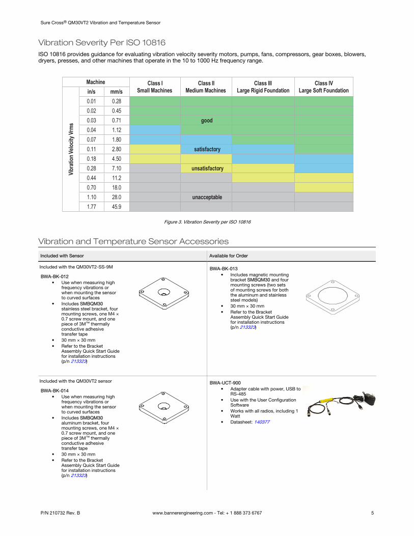
Vibration Severity Per ISO 10816ISO 10816 provides guidance for evaluating vibration velocity severity motors, pumps, fans, compressors, gear boxes, blowers,dryers, presses, and other machines that operate in the 10 to 1000 Hz frequency range.
Banner Engineering Corp. warrants its products to be free from defects in material and workmanship for one year following the date of shipment. Banner Engineering Corp. will repair orreplace, free of charge, any product of its manufacture which, at the time it is returned to the factory, is found to have been defective during the warranty period. This warranty does notcover damage or liability for misuse, abuse, or the improper application or installation of the Banner product.
THIS LIMITED WARRANTY IS EXCLUSIVE AND IN LIEU OF ALL OTHER WARRANTIES WHETHER EXPRESS OR IMPLIED (INCLUDING, WITHOUT LIMITATION, ANY WARRANTY OFMERCHANTABILITY OR FITNESS FOR A PARTICULAR PURPOSE), AND WHETHER ARISING UNDER COURSE OF PERFORMANCE, COURSE OF DEALING OR TRADE USAGE.
This Warranty is exclusive and limited to repair or, at the discretion of Banner Engineering Corp., replacement. IN NO EVENT SHALL BANNER ENGINEERING CORP. BE LIABLE TOBUYER OR ANY OTHER PERSON OR ENTITY FOR ANY EXTRA COSTS, EXPENSES, LOSSES, LOSS OF PROFITS, OR ANY INCIDENTAL, CONSEQUENTIAL OR SPECIAL DAMAGESRESULTING FROM ANY PRODUCT DEFECT OR FROM THE USE OR INABILITY TO USE THE PRODUCT, WHETHER ARISING IN CONTRACT OR WARRANTY, STATUTE, TORT,STRICT LIABILITY, NEGLIGENCE, OR OTHERWISE.
Banner Engineering Corp. reserves the right to change, modify or improve the design of the product without assuming any obligations or liabilities relating to any product previouslymanufactured by Banner Engineering Corp. Any misuse, abuse, or improper application or installation of this product or use of the product for personal protection applications when theproduct is identified as not intended for such purposes will void the product warranty. Any modifications to this product without prior express approval by Banner Engineering Corp willvoid the product warranties. All specifications published in this document are subject to change; Banner reserves the right to modify product specifications or update documentation atany time. Specifications and product information in English supersede that which is provided in any other language. For the most recent version of any documentation, refer to: www.bannerengineering.com.
For patent information, see www.bannerengineering.com/patents.
FCC Part 15 and CAN ICES-3 (B)/NMB-3(B)This device complies with part 15 of the FCC Rules and CAN ICES-3 (B)/NMB-3(B). Operation is subject to the following two conditions:
1. This device may not cause harmful interference, and2. This device must accept any interference received, including interference that may cause undesired operation.
This equipment has been tested and found to comply with the limits for a Class B digital device, pursuant to part 15 of the FCC Rules and CAN ICES-3 (B)/NMB-3(B). These limits aredesigned to provide reasonable protection against harmful interference in a residential installation. This equipment generates, uses and can radiate radio frequency energy and, if notinstalled and used in accordance with the instructions, may cause harmful interference to radio communications. However, there is no guarantee that interference will not occur in aparticular installation. If this equipment does cause harmful interference to radio or television reception, which can be determined by turning the equipment off and on, the user isencouraged to try to correct the interference by one or more of the following measures:
• Reorient or relocate the receiving antenna.• Increase the separation between the equipment and receiver.• Connect the equipment into an outlet on a circuit different from that to which the receiver is connected.• Consult the manufacturer.
Sure Cross® QM30VT2 Vibration and Temperature Sensor