+ All Categories
Home > Documents > (QoS in UMTS) - DiVA portal831045/FULLTEXT01.pdf · (QoS in UMTS) ... Table 4.2 Radio Access Bearer...

(QoS in UMTS) - DiVA portal831045/FULLTEXT01.pdf · (QoS in UMTS) ... Table 4.2 Radio Access Bearer...

Date post: 16-Mar-2018
Category:
Upload: lexuyen
View: 226 times
Download: 0 times
Share this document with a friend
53
i Thesis number: MEE09:46 ROUTING FOR QoS IN AD HOC WIRELESS NETWORKS (QoS in UMTS) Presented by: Onuzulike Vincent Chukwuma 740923-P177 Department of Telecommunication Systems Blekinge Institute of Technology Campus Gräsvik, Karlskrona Sweden December, 2008 Supervisor: Professor Adrian Popescu BTH, Karlskrona Sweden
Transcript

i

Thesis number: MEE09:46 ROUTING FOR QoS IN AD HOC WIRELESS NETWORKS

(QoS in UMTS)

Presented by: Onuzulike Vincent Chukwuma 740923-P177

Department of Telecommunication Systems

Blekinge Institute of Technology

Campus Gräsvik, Karlskrona

Sweden

December, 2008

Supervisor: Professor Adrian Popescu

BTH, Karlskrona Sweden

ABSTRACT Ad hoc network is a collection of wireless mobile nodes which dynamically form a

temporary network without the use of any pre-existing network infrastructure or

centralized administration. They operate by interactions among their neighbourhood

wireless mobile nodes. Such interactions provide the required administration and control

functions that support networks of that nature. Ad hoc wireless networks provide

significant advantages on wide environments and certain applications. These types of

networks could be internally fault-resilient, since they do not work under fixed topology.

However, the networks are time-varying since all the nodes operate as mobile. Ad hoc

networks automatically adapt to environments which are at the extremes of high mobility

with low bandwidth and vice versa. In an ad hoc network that is multi-hop and for two

nodes that are not direct neighbours, the communication between these nodes require that

there should be a relay of message by the node that is in between them. Each of these

nodes in the network acts as a router and also as a communication end-point. The

cooperation and collaboration of all network layers is required for the provision of QoS

support. Growth in wireless communication has been very astronomical in the past few years.

Every technology is going wireless. Quality of service is a big issue that has to be

addressed. Our main concern here is QoS routing. Every node broadcasts beacon packets

periodically identifying it and its QoS characteristics. In the centre of ad hoc networking

lies beaconing mechanism because without this, a node will not know its adjacent

neighbours that changes dynamically in an ad hoc networking scenario. For routing, the

knowledge of adjacent neighbours is very essential. To support QoS for real time traffic

we need to know not only the minimum delay path to destination, but also the bandwidth

available on it. We would also deal with how to improve QoS in an ad hoc wireless

network; and Universal Mobile Telecommunications Systems (UMTS). QoS in an ad hoc

wireless network pose a complex issue because of dynamic nature of the network

topology; but, it would be addressed here.

iii

ACKNOWLEGDEMENT

My special thanks go to the Almighty God, for his love and guidance in the course of this

programme. All glory remains yours forever.

I would not fail to express our warmth gratitude to our beloved wives, for their emotional

love and support during this period. May I also thank my parents, brothers and sisters for

their financial and moral supports throughout the difficult time. Thanks to all my friends

and well wishers who contributed immensely in this work. I love you all.

Also, I appreciate the effort of Professor Adrian Popescu for his untimely sacrifice in

making this work a success. Thanks for your fatherly advice and supervision. My sincere

regards also goes to all the lecturers in Electrical Engineering Department; especially, the

Program Manager Mr. Mikael Asman for his un-relented guidance throughout this

program. God will reward you all.

TABLE OF CONTENT Pages

Title page i Abstract ii Acknowledgement iii Table of content iv List of figures v List of tables v 1.0 CHAPTER 1: Introduction 1 1.1 Overview 1 1.2 Motivation 2 1.3 Thesis Organisation 2 1.4 Thesis Contributions 3 1.5 Problem Statement: QoS Routing in Ad Hoc Wireless Networks 3 1.6 Chapter Summary 3 2.0 CHAPTER 2: BACKGROUNDS 4 2.1 A Brief History of Wireless Networks and Ad Hoc scenarios 4 2.2 Introduction of Ad Hoc Networks 5 2.3 Principles Operation of Ad Hoc Networks 5 2.4 Properties of an Efficient Routing Algorithm 6 2.5 Routing in Mobile Ad Hoc Networks 8 2.6 Classification of routing algorithms for Ad Hoc Networks 8 2.7 Chapter Summary 13 3.0 CHAPTER 3: ROUTING MECHANISM FOR THE SUPPORT OF QoS IN MOBILE AD HOC WIRELESS NETWORKS 14 3.1 Introduction 14 3.2 Network Layer QoS Support in Ad Hoc Wireless Networks 14 3.3 Wireless flow management system 16 3.4 Admission Control and Medium Access Control 18 3.5 Chapter Summary 25 4.0 QoS for UMTS 26 4.1 Brief History of UMTS 26 4.2 UMTS QoS Architecture 26 4.3 QoS Functionality 29 4.4 QoS Implementation in UMTS 30 4.5 Radio Access Bearer (RAB) QoS Attributes 33 4.6 Mapping method From UMTS QoS to RAB QoS 33 4.7 Realization of QoS in User Plane over Iu Interface 35 4.8 Chapter Summary 36 5.0 CHAPTER 5 MOBILITY PATTERN ADAPTIVE ROUTING PROTOCOL 37 5.1 Protocol Description 37 5.2 Mobility Pattern Aware Routing Protocol 40 5.3 Implications of the new Technique 40 5.4 Provision for Imposing QoS Routing 42 5.5 Chapter Summary 43

v

6.0 CHAPTER 6.0 CONCLUSION AND FUTURE WORK 44 References 45 List of figures page

Fig. 2.1 Fisheye State Routing information 11

Fig. 2.2 Hierarchical State Routing (HSR) tree-like 11

Fig. 3.1 QoS Architecture 15

Fig.3.2 Module diagram for BS and SS 17

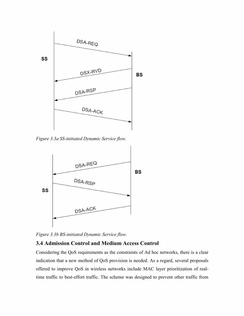
Fig. 3.3a SS-initiated Dynamic Service flow 18

Fig. 3.3b BS-initiated Dynamic Service flow 18

Fig. 3.4 Hidden/ Exposed terminal in MAC protocol 24

Fig. 4.1 UMTS QoS Architecture 27

Fig. 4.2 UMTS Phase network 29

List of tables

Table 4.1 UMTS QoS classes 33

Table 4.2 Radio Access Bearer Attributes 33

Table 4.3 User QoS Attributes 34

Table 5.1 Sample Routing table 38

Table 5.2 Routing table 38

Table 5.3 Sample Routing update 41

Table 5.4 New Routing table 43

1

CHAPTER 1 1.0 Introduction 1.1 Overview

Emergence of wireless networks since 1970s, has drastically dominated the network

industry. It can afford mobile users with communication capability and access to

information despite locations. Conventional wireless networks are often connected to a

wired network so that the ATM or Internet connections can be extended to mobile users.

Wireless network requires a fixed wired line backbone infrastructure. All mobile hosts in

a communication cell can reach a base station on the wire line network in one-hop radio

transmission. Similar to conventional wireless networks, another type of model exits.

This type of wireless network is based on radio to radio multi-hopping and has neither

fixed base stations nor a wired backbone infrastructure.

It is applicable in some environments, such as battlefield communications, monitoring of

natural disaster, mission-critical applications etc. Where wired network is unavailable,

multi-hop wireless networks serves as the only achievable means for information

transmission. This kind of network is called Mobile Ad hoc NETwork (MANET). It

plays an important role in civilian forums such as campus recreation, conferences and

classrooms etc. Mobile Ad hoc Network operates as an autonomous system or a multi-

hop wireless extension to the Internet. Independently, MANET possess own routing

protocols and network management systems. Increasing use of multimedia applications

of MANETs, has made QoS support in MANETs an unavoidably task to fulfilled.

This thesis work would focus on Quality of Service (QoS) routing in MANETs.

Routing is an actively researched area for mobile ad hoc networks. MANET’s section of

the Internet Engineering Task Force (IETF) has contributed immensely in this research

area.

1.2 Motivation

The network topology changes as the nodes move in a Mobile Ad hoc Networks

(MANETs). As a result, information is subject of becoming outdated, and different nodes

often have different views of the network. It occurs both in time (some nodes can have

outdated information while some have recent ones) and in space (a node can only

recognized the network topology within its neighborhood, but not ones far from itself).

These routing protocols need to adapt to the frequent topology changes and with

minimum correct information. Routing in MANETs takes a different form, unlike others.

Sourcing for new information about the entire network is a very costly task and always

poses problems [2]. It is very essential that protocol should be adaptive. Often, route

optimality is secondary to the correctness (loop-freedom) of these routes.

Routing for Quality-of-service in mobile ad hoc networks is quite an unexplored area.

The protocol does not only find a route so as to provide QoS, but it also secures the

resources along the route. Thus, nodes must reach a consensus with each other to control

the resources required for QoS routes. This is because of the limited and shared

bandwidth of the network which lacks central controller for limited resources. Frequent

topology changes even make it more difficult. As a result of these constraints, QoS

routing is more demanding than best effort routing. Our motivation is to implement

complex QoS functionality with limited available resources in a dynamic environment.

1.3 Thesis Organization The organization of the rest of the thesis is as follows. In Chapter 2, we describe the

backgrounds. Chapter 3 introduces the routing mechanisms for the support of QoS in

Mobile Ad hoc networks. Chapters 4 and 5 introduce the QoS for Universal Mobile

Telecommunication System (UMTS) and Mobility Pattern Adaptive Routing Protocols

respectively. Finally, we concluded the thesis in chapter 6. Because the research on QoS

in MANETs is a new research of interest, future work is also proposed in the last chapter.

References were made in the last section of this work.

3

1.4 Thesis contributions

As a result of bandwidth constraint and topology changes in Mobile Ad hoc NETworks

(MANET), supporting Quality of Service (QoS) in MANETs has become a big challenge.

This thesis review the current research on QoS support in MANETs, which includes, QoS

routing algorithms, QoS Admission control, QoS Medium Access Control (MAC),

Multiple Access Collision Avoidance with Piggyback Reservation (MACA/PR), QoS

functionality and QoS aware routing. The purpose of this paper is in two folds. Firstly,

we described a whole picture of QoS support in MANETs; described in totality and

accompanied the challenges, solutions and future research in this area.

1.5 Problem Statement: “QoS Routing in Ad Hoc Wireless Networks”

Real-time applications over Ad hoc wireless networks have strict quality of service (QoS)

requirements. High delivery rates of data packets and low end-to-end delays are among

the requirements [13]. It is very vital that these requirements are met by overcoming

some of these constraints that network faces. Thus, QoS routing in Ad hoc wireless

networks will guarantee effective network applications and ensure that the perceived

quality of service that the user experiences will not suffer.

1.6 Chapter Summary

This chapter has given brief overview of Mobile Ad hoc Networks (MANETs). However,

the need to implement QoS functionalities in order to ensure efficient networks is very

understanding. QoS routing in MANET is a very challenging area of study due to some

constraints such as bandwidth requirement, packet-loss, packet delay and frequent

topology changes. Solutions for QoS guarantee support was also highlighted, but;

detailed discussion and future work will be in the subsequent chapters.

CHAPTER 2

2.0 Backgrounds 2.1 A Brief History of Wireless Networks and Ad Hoc Scenarios Ad hoc networks originated from the program “Packet Radio Network (PRNET)”

established by Department of Defense (DoD) in early 1970’s. Some years later in 1983, it

gave birth to Survivable Adaptive Radio Network (SURAN). This approach was aimed to

establish packet-switched networking to mobile used by soldiers in the battlefield [3, 19].

It was moved towards small-sized, low-cost and low-power radio. It developed and

demonstrates robustness and survivability against sophisticated attacks.

Throughout 1980’s, it used ALOHA/ CSMA spread spectrum. ALOHA joined with

CSMA were used for medium access and distance routing. As a result of this, a

remarkable improvement was recorded on the radios in the area of portability, low cost,

efficient services and resistance to environmental constraints. The Army did not adopt the

New MANET not until it was demonstrated experimentally in the mid- 80’s. They used it

for land-based applications; usually as overlays to the existing networks [4]. Navy ships

used it on the sea, because of its less density to ground networks. The Air force also

explored it for provision of communications between ground stations.

On getting to early 1990’s, Ad hoc networking moved to some advanced development. A

lot of standard activities came up in mid 90’s. At that time, the MANET working group

(within the IETF) standardized routing protocols for ad hoc networks. The IEEE 802.11

subcommittee also standardized an ad hoc mode MAC layer which made it possible to

build ad hoc networks using laptops. RF and Infrared-based equipments were also

produced. Later, several standards like HIPERLAN and Bluetooth emerged.

DoD also supported Global Mobile Information System (GLoMo) and Near-term Digital

Radio (NTDR) programs. GloMo enhances multimedia connectivity. Also, Channel

Access Scheme was developed in CSMA/CA and TDMA.

5

2.2 Introduction to Ad Hoc Networks

Ad hoc network can be defined as an assembly of communication nodes willing to

communicate with one another over a wireless medium. There is no fixed infrastructure

in an ad hoc network, unlike in the cellular networks. Such devices can communicate

with another node that is immediately within their radio range (peer-to-peer

communication) or one that is outside their radio range (remote-to-remote

communication) using intermediate node(s) to relay or forward the packet from the

source (sender) toward the destination (receiver) [6]. Power consumption is a serious

issue in an ad hoc networks, since it rely on forwarding data packets sent by other nodes.

Ad hoc networks are self-creating, self-organizing and self-administering. That is to say

that a formed network can be deformed while on transit without the need for any system

administration.

Ad hoc network is mostly used in conditions where there is non-availability of

infrastructure, unreliable or entrusted networks especially under emergency conditions.

Example of such communication capacity of an ad hoc networking can be applied in

military war fighters in the battlefield, conferencing, sensor networks, home networking,

embedded computing and personal area networking.

Due to lack of wired infrastructures and power control, there is always a problem of

constant changes in the connectivity and link characteristics in ad hoc networks. In an ad

hoc networking, multi-layer problem is always the case. Here, the physical layer should

adapt to the constant changes in the link characteristics. It is important that ad hoc

network applications should be design in such a way that it will handle connectivity

problems. Packet delay and lost problems as well, have to be put into consideration when

designing the network.

2.3 Principles of Operation

Much wireless technology is based upon the principles of direct point-to-point

communication. Popular solutions like Group Standard for Mobile communication

(GSM) and Wireless Local Area Network (WLAN) both use an approach where mobile

nodes communication directly with some centralized access point. These types of

networks demand centralization for configuration and operation.

But, multi-loop application is the opposite of this model. Nodes can relate by using other

nodes in form of relays for transport if the endpoint is not in same communication

network.

Mobile ad-hoc networks MANET, operates in multi-loop type. All the nodes are mobile,

thereby forming a dynamic network. In this context, there may be no room for a priority

classification, since all nodes are required to cooperate in supporting the network

operation, while no prior security association can be assumed for all the network nodes.

Furthermore, in MANET, freely roaming nodes form transient associations with their

neighbors, join and leave MANET sub-domains independently and without notice. Most

times, ad hoc network membership is hard to ascertain. Also, in the case of a large-size

network, no form of established trust relationships among the majority of nodes could be

assumed. In this type of scenario, there is no guarantee that a path between two nodes

would be free of malicious nodes, which would not comply with the employed protocol

and attempt to harm the network operation.

2.4. Properties of Efficient Routing Algorithms

2.4.1. Finding path with minimal guaranteed delay

One of the major properties of efficient routing is the ability to provide end-to-end

guarantees, such as delay. This depends greatly on scheduling, policy and service

discipline applied in the nodes. Such disciplines are characterized by bounds on the

maximal delay that any node can acquire and hence a corresponding bound on the end-to-

end delay can be derived. Such bounds provide a valuable tool for quantifying the quality

of a path in terms of its ability to meet the QoS delay requirement. In this case, the

routing problem is to identify the route that has the best minimal guaranteed and QoS

requirements.

7

2.4.2. Finding a feasible paths

Among other properties of efficient routing for QoS are finding feasible paths for the

networks. We can observed that for a given connections with end-to-end delay constraint,

the existence and identity of a feasible path can be obtained through up to M executions

of standard shortest-path algorithms, where M is the number of network links. Whenever

connection is feasible, the path and rate identified by the algorithm, achieve a minimal

cost among all feasible solutions.

2.4.3. Optimization of the path selection

It can be seen that the ability to identify a feasible path for a connection does not yield yet

a satisfactory QoS routing solution. Therefore, in order to supervise multiple connections

across the networks, the routing algorithm must carefully select an “optimal” path among

the feasible ones. Here, we focus on the criteria that optimize the consumption of rates.

With rate-based schedulers, the amount of rate allocated to a connection is not fixed a

priori but rather depends on the path selection. One may decide to minimize the overall

reduction of rates imposed by the connection. In that case, an optimal path is the one that

minimizes the sum of the consumed rates over all links.

2.4.4. Distributed protocols

In practice, the path selection relies on some distributed protocol. Focusing on the basic

problems of finding a path with minimal guaranteed delay, we proceed to discuss the two

typical schemes of Distance-Vector and Link-State protocols. Both types find the shortest

path to destinations.

In distance vector (DV), each router informs it neighboring nodes about its routing table

and chooses the destination path with lowest cost. DV protocols are generally known to

suffer from slow route convergence and a tendency to create loops in mobile

environments [8].

The Link State (LS) routing algorithm overcomes the problem by maintaining global

network topology information at each router through periodical flooding of link

information about its neighbors [9]. In this context, it is a condition where each node

should be updated with the current parameters of the various links.

2.5 Ad hoc Networks Routing

Nodes co-operate in the routing process to execute multi-hop forwarding. Here, each

node functions not only as a host but also as a router that maintains routes to and forward

data packets for other nodes in the network that may not be within direct wireless

transmission range.

Routing in ad hoc networks faces extreme challenges from node mobility/dynamics,

potentially very large numbers of nodes and limited communication resources (e.g.

bandwidth and energy). These problems are categorized into two standard forms, Hidden

terminal problems: two nodes out of signal range try to send to the same receiver. Some

relief of this can be achieved with control messages (Request-to-send and Clear –to-

send). Exposed node problems: for example, C is transmitting to D; B overhears this and

is blocked. B wants to transmit to A, but is being blocked. This leads to wastage of

bandwidth. For this reason, routing protocols for an ad hoc wireless networks have to

cope fast to regular and unpredictable topology changes.

Because of the fact that bandwidth is scare in MANET nodes and the population in a

MANET is small to compare with that of the wireline internet, the scalability issue for

wireless multi-hop routing protocols is mostly concerned with excessive routing message

overhead caused by the increase of network population and mobility.

Routing table size plays an important role in MANET. A large routing table means a

large control packet size and hence large link overhead.

2.6 Classification of Routing Algorithms for Ad Hoc Networks

Routing in ad hoc networks is classified according to the routing strategy and network

structure underlying routing protocols. Different structures affect the design, operations

of the routing protocols and also determine the performance based on the scalability.

In ad hoc networks, there are two major categories of routing algorithm.

(i) Proactive Routing algorithm.

(ii) Reactive Routing algorithm.

9

2.6.1. Proactive routing protocols

These types of routing protocols have thus same common properties. They have many

advantages in areas especially real-time communications and QoS guarantees such as

low-latency route access and alternate QoS path support and monitoring. Each node

calculates proactively consistent and up-to-date routing tables, which are periodically or

on-demand exchanged between the nodes. The network status is updated in the whole

network by nodes whenever there are network topology changes.

Classification of Proactive Routing algorithm is shown as follows.

(a) Destination-sequenced Distance Vector (DSDV)

(b) Wireless Routing protocols (WRP)

(c) Fisheye State Routing (FSR)

(d) Hierarchical State Routing (HSR)

2.6.1.1 Destination-Sequence Distance-Vector (DSDV)

This is classically based on Bell-ford Routing (distance-vector-algorithm). It continues to

have in each node a routing table which records all obtainable destinations with sequence

number of the hops [11].

Periodically, the node broadcasts to its neighboring nodes the latest estimate of the

shortest distance to its neighboring nodes. Updated packet of DSDV has a unique

sequence number (SN). The SN is been allocated by the transmitter and the receiver picks

the packet with the newer SN. In a situation where more than one packet has the same

SN, the route with best cost metric is chosen [11].

2.6.1.2 Wireless Routing Protocol (WRP)

WRP has related features as DSDV. It maintains a Distance table, a Routing table and

Link cost table, as well as message retransmission list table in each node. Distance table

contains distance to any destination through every neighboring node, the Routing table

contains the predecessor and successor nodes on the path which helps to find to the

shortest path. The Link cost table contains the cost of the link to each neighboring node.

Once an update message is sent to a neighboring node, the receiver modifies their

distance table if needed and check for new paths using other nodes. At this point, the new

information is returned to the original node, so as to update their own routing tables

accordingly.

2.6.1.3 Fisheye State Routing (FSR)

FSR is proactive and table –driven. It promotes the Global State Routing (GSR)

algorithm has similarity with Distance-sequence Distance vector method. The major

work of FSR is to lower updates overheads and enable network scaling with large number

of nodes.

Figure1.below represents the information quality reduction scope in FSR.

Fig 2.1 Information in FSR decreases to the edge. (Telematics, 2004)

Its details diminish as the distance from the centre point enlarges. Updated packet size

can be reduced by FSR through sending information of the nodes within neighboring

11

range more often than those of the far nodes. Exact information of neighboring nodes is

revealed to each node in FSR network.

2.6.1.4 Hierarchical State Routing (HSR)

This is another proactive algorithm which partitions the network nodes into multi-layer

clusters. In each cluster, one node is cluster-parent and these cluster-parents are organized

in a higher-level of clusters. Some of the nodes are found in more than one cluster. Such

nodes are called gateways and each node possesses network address.

When routing is modified, each node broadcasts information in their cluster. Cluster-

parent sends the information to all neighboring cluster-parents and this extends to their

lower level, informing all the nodes about the changes in the network. HSR forms a tree-

like hierarchy.

Fig.2.2 HSR tree-like hierarchy of topology clustering (Telematic, 2004)

2.6.2 Reactive Routing Algorithms

Unlike proactive routing which keep clear routes; reactive routing algorithms calculate

routing information only when data is ready to be transmitted with sluggish routing

method. The arranged route is regarded valid provided the destination is attainable or

until the route is needless. Reactive routing protocols avoid the traffic flood and the

overhead of periodic routing calculation.

Classification of Reactive routing algorithms is as the follows.

(a) Signal Stability Adaptive Routing(SSR)

(b) Temporally Ordered Routing Algorithm (TORA)

(c) Ad Hoc On-Demand Distance Vector Routing(AODV)

(d) Efficient Route Update Protocols (ERUP)

2.6.2.1Signal Stability Adaptive Routing (SSR)

Signal Stability Adaptive Routing Protocol is responsible for calculating a route between

two nodes on stronger connectivity base. It is calculated as the signal strength together

with the stability of the nodes. It maintains two tables, a Signal Stability Table (SST) and

a Routing Table. Signal strength of the neighboring nodes is stored in the Signal Stability

Table, while the routes are kept in the routing table.

SSR routing operates in two internal protocols, the Dynamic Routing Protocol (DRP) and

Static Routing Protocol (SRP) which controls SST and RT, respectively.

2.6.2.2 Temporally Ordered Routing Algorithm (TORA).

The principle of TORA is mainly link reversal. Its routing algorithm is adaptive,

efficient, distributive, scalable and reactive in nature. The three main functions of

(TORA) are: creating routes, route maintenance and erasing route. TORA is somehow a

complicated protocol, but has the feature of patching itself around a failed point when

link fails.

2.6.2.3 Efficient Route Update Protocol (ERUP)

It is based on AODV. ERUP combines routing with power saving. The Route update in is

divided in two levels. Nodes along the old route broadcast locally a Route Discovery

Region packet (RDR) [2]. This RDR defines the spreading area of Route Request packets

(RRQ). The source node releases RRQ and only nodes within the RDR can rebroadcast

this RRQ.

13

2.7 Chapter Summary

Considering the huge increase in mobile wireless communication, both for speech and

data services, it is important to provide end-to-end QoS to support a variety of

applications for both operators and users. Numbers of QoS route approach have been

proposed in literature, focusing on different metrics. No particular protocol has provided

a final solution. More effort has to be made by new researchers to achieve a great height

in this area.

Chapter3

3.0 Routing Mechanism for the Support in Mobile Ad Hoc Wireless

Networks

3.1 Introduction

Wireless Ad hoc networks consist of a collection of mobile node, which are

interconnected by multi-hop wireless paths with wireless transmitters and receivers. Each

node may work as a router for other nodes in same transmission range. Use of multimedia

applications in communication has created the demand for QoS support in mobile Ad hoc

networks and ensures reliable route to QoS requirements. Because of the dynamic

changes in the network topology and limited wireless channel bandwidth, provision of

QoS is complex and challenging. Due to the difficulties in predicting link states

associated with dynamic changes in network topology, QoS studies tends to focus only

on one of the several constraints. Among the constraints is packet loss, end-to-end delay

or bandwidth. For example, while many of the QoS-related mechanisms are appropriate

in reducing packet-loss by adding redundancy in the packet, end-to-end delay is

increased. Packet lost and end-to-end delay is inversely proportional to each other in this

mechanism and therefore, it is impossible to guarantee a path way that would satisfy

delay, bandwidth and packet loss constraints.

In this chapter, we discussed the network layer support for QoS in Ad hoc wireless

networks, variable data flow management in wireless sensing networks, admission

control and medium access control in Ad hoc wireless networks. Also, analyzed are some

hybrid methods that enhance network performances for QoS support in a mobile Ad hoc

network.

3.2 Network Layer QoS Support in Ad Hoc Wireless Networks

Various routing protocols have been proposed in the past for either to provide admission

control or find a path with large enough bandwidth to support a given request. Packet

queue management in the link layer and performance evaluation of different queue

scheduling algorithms with the DSR and GPSR routing protocols have been discussed by

many literatures, too. Priority scheduling in the MAC layer has also received some study

research. All these protocols improve the support for real-time data transmission in

15

Mobile Ad hoc Networks (MANETs). Effective data communication is the end product

of each network layer’s effort. Thus, the co-operation of all network layers is needed to

provide QoS support. Below is a QoS architecture that includes all the networking

layers. It extends from the application layer to the MAC layer to support real-time data

transmission. The QoS architecture includes a QoS transport layer, QoS routing, queue

management and a priority Medium Access Control protocol.

Figure 3.1 QoS architecture (“Network Architecture to Support QoS in MANET”, Univ.

NY 2004)

The bold lines represent the flow of data packets, while the thin lines indicate the flow of

control packets. Simultaneously, non QoS-aware routing targeted at finding a feasible

path should be offered too. Information of the current network position is required to be

made available to the application in QoS-aware routing for performance improvement

[12]. Therefore, two cross-layer designs should be implemented in QoS-aware routing.

Firstly, network resource information needs to be obtained from lower layers, and

secondly send the network status to the applications. In order to extend QoS to the

applications, resource reservation should be incorporated. The transmissions that occur

between the breakdown of old routes and the set up of new routes will severely affect the

QoS provided by the network. As a result, some route breaks focast should be involved.

Finally, QoS-aware routing should have the following features

- obtain resource information from lower layers;

- offer bandwidth information to applications;

- incorporate resource reservation schemes; and

- predict route breaks [12].

3.3 Wireless Flow Management System

Previous work done by IEEE 802.16 standard on mechanism for QoS guarantee traffic

flow does not clearly define the scheduling algorithms for uplink and downlink

bandwidth allocation in a single frame.

The proposed QoS flow management system comprises: the admission control, the

classifier and the packet scheduler. Signaling protocol establishes the routes and reserve

resources before their data can be transmitted. The admission control routines will decide

whether a request for resources can be granted. After classification of packets in a

specific queue, the packet scheduler will then schedule the packet to meet its QoS

requirement [14]. The priority classifier differentiates the different data packets that

arrive from the packet queue and directs the packet scheduler to schedule the packet

delivery based on the priority level of the current packet.

A PATH message is send to the receiver to specify the characteristics of the flow. The

receiver responds with a RESV message to reserve resources for the flow. The flow

should be refreshed at intervals. QoS signaling operations and functions are well

elaborated in MAC layer to control data transmission between Base Station and Service

Station. Refer to fig. (3.2) below. These service flows can be made, changed, or removed

through Dynamic Service Addition (DSA), Dynamic Service Change (DSC), and

Dynamic Service Deletion (DSD) messages. Every one of these actions can be introduced

by the SS or the BS and are executed through a two or three-way-handshake as shown in

fig. (3.3a & b) below. For example, when SS detects the appearance of a fresh service

flow, it will calculate the available bandwidth to determine if a DSA request will be sent

17

or not. When the DSA request is received, the BS verifies whether this request can be

supported, and sends a DSA response.

Depending on the message of the DSA response, the SS finally sends a DSA

acknowledgement and enables the new service flow if the request is granted. DSA

messages carry the maximum sustained traffic rate (rmax) and the minimum reserved

traffic rate (rmin).

Figure 3.2 Module diagram for BS and SS (ACM IEEE 802.162001 2006)

Figure 3.3a SS-initiated Dynamic Service flow.

Figure 3.3b BS-initiated Dynamic Service flow.

3.4 Admission Control and Medium Access Control

Considering the QoS requirements as the constraints of Ad hoc networks, there is a clear

indication that a new method of QoS provision is needed. As a regard, several proposals

offered to improve QoS in wireless networks include MAC layer prioritization of real-

time traffic to best-effort traffic. The scheme was designed to prevent other traffic from

19

interfering with real-time traffic, but it permits uncontrollable increase in the amount of

real-time traffic in the network. As a result, the performance of the network worsens in

the process. One challenge that is required to be tackled is to avoid over-utilization of the

wireless route [13]. This can be achieved through admission control. Flow cannot resume

without seeking for the consent of admission control when it is in place. Information

about the current and new flow is used by this mechanism to determine if new flow

would be allowed to begin.

New data is allowed to flow onto the network by admission control, if the available

network bandwidth is greater than the bandwidth required by the flow. At this point,

admission control estimates the available network bandwidth and the bandwidth required

by the flow. It must ensure enough available bandwidth on the narrow link of the route,

because congestion may differ on each link. More so, it makes sure that the admission of

a new flow does not obstruct the existing flows on neighboring connections. Admission

control uses a CSMA/CA based system to control access to the wireless channel [15].

However, available bandwidth is link-dependent due to differences in bit rate and packet

error rate (the same node can have different bandwidth available for different

communication links).

Equally, it is vital to consider the node’s channel availability in terms of time, so long as

it does not dependent on these factors. We define a node’s channel availability as the

fraction of the channel available for transmissions without interfering with existing flows

on its CSNs. The required link utilization of a flow depends on the data rate and packet

size used by the flow together with the bit rate on the link. Because of self-interference of

flows in wireless networks, the link utilization is also affected by the fraction of channel

the flow consumes on other neighboring links.

3.4.1 Admission Control

Here, we discuss different mechanisms in which admission control can be applied in an

Ad hoc network to ensure quality of service (QoS). In the local or single-hop admission

control, we have two previously used methods: Contention-aware Admission Control

Protocol (CACP) and Perceptive Admission Control (PAC).

3.4.1.1 Contention-aware Admission Control Protocol

Particularly, Contention-aware Admission Control Protocol (CACP) was designed for the

special properties of wireless networks. Local available resources are considered when

taking admission decisions and nodes within carrier-sensing range are useful in

calculation. The duty of the nodes is to perform channel busy-time measurements. It also

calculates the available bandwidth in order to determine the local available bandwidth.

The query message can be flood to all the nodes within its limit using multi-hop principle

or through a high power transmission. But in multi-hop approach, some nodes within

carrier sensing range may not be reached through any path. Problem with the high power

transmission is that it introduces more interference and collisions into the network. On

receiving message, a node accesses its local measured bandwidth in order to decide if the

flow should be allowed. So if the flow would not be allowed, a feedback is send to the

source to stop the admission of the flow.

3.4.1.2 Perceptive Admission Control

The system of query used by CACP can reserve bandwidth in an unwanted large area. In

addition, negative acknowledgments used in rejecting admissions flows cause huge

improper admission decisions. Perceptive Admission Control protocol (PAC) is

recommendable to for all these problems. PAC reduces the protocol overhead and risk of

making mistakes in admission decisions. It does not require the transmission of any

control messages. As busy-time measurement in CACP determines the available

bandwidth, the PAC extends the range for that measurement. The reason for this function

is to make it possible for the nodes to take admission control decisions without

communicating with other nodes. This can only be achieved by enlarging the busy time-

measurement so as to overcome the minimum length needed for two transmissions to

occur at the same time without collision. Local available bandwidth has to be considered

before admission control decision can be made by the node.

Despite admission control decision, areas around the network can become congested. In

PAC, the nodes continuously monitor the available bandwidth to avoid this problem.

When there is an existing traffic flow in a node and the available bandwidth goes below a

threshold value, the flow source should put the transmission to a stop. The node can

attempt to re-admit an initial denied flow after a randomly selected back-off time, in the

21

hope that either more bandwidth has become available, or that another path is available.

3.4.1.3 Multi-path Admission control

Considering only the available bandwidth at a single node in an Ad hoc network is

insufficient. For admission control to perform properly in the presence of mobility, Multi-

path Admission Control for Mobile Ad hoc Networks should be applied [13]. Fresh

admission flow cannot be allowed unless enough available bandwidth which will support

the transmission along the path is present. Thus, the contention count (CC) is calculated

below in (Equ.3.2) as the multiple of bandwidth needed by the flow to be admitted.

CC = |CSN ∩ R \ {D} | (3.2)

Here, CSN= group of nodes within carrier sensing range of the node (including the

source node itself), R= group of nodes on the route from source to destination and,

D= destination.

Multi-path admission control is based on CACP and PAC in order to achieve flows to

meet their QoS requirements in a mobile Ad hoc network. Both protocols do the work of

discovery and maintenance of multiple paths which offer the needed QoS between the

source and the destination. It enables a source for fast switching over to an alternate path

when the current path gets unstable. Multi-path admission control operates in three

sections: the route discovery, route maintenance and route updates through proactive

RREQs.

Route discovery: This section of Multi-path Admission Control in Mobile Ad hoc

Networks (MACMAN) discovers routes that fulfill the QoS required to allow a new flow.

The route discovery process can be modified easily, as source routing is used in the

multiple paths [13]. The destination send replies to the source in respect to the first and

subsequent route requests received. The best route is chose for transmission as the replies

approach the route source. The route that posses the shortest path is used, for example.

Other routes are also caught for further use.

Route maintenance: Catching multiple routes poses a problem of the routes getting stale

during route discovery. As a result, they become invalid when required, may be because

the route has broken, or cannot provide the required QoS. MACMAN monitors each

alternative route in the cache often to avoid stale routes commutation. Route Capacity

Query (RCQ) messages are received at the destination, periodically. As in the route

requests, the RCQ messages contain the bandwidth requirement of the flow. It also

contains a list of the route that is currently being used to transmit the flow. Each node

along an alternate route has to determine if it is still valid for the flow when it receives a

Route Capacity Query (RCQ). This is because the flow is currently being transit along

another route. But when there has been flow transmitted on the new route, the

transmission on the current route would end. Consequently, if the flow transmission in

the current is stopped, it will reduce the measured available bandwidth along the alternate

route. The available bandwidth is not properly quantified and routes are subsequently

deleted in the process. Transmission of the flow in a new path leads to an

increase/decrease in the contention. The Contention Difference (CD) can be determined

with (Eq.3.3). When a node receives a RCQ,

CD = | CSN ∩ Rnew \{D}| - | CSN ∩ Rcurr\ {D}| (3.3)

Where Rnew is the route on which the RCQ is transmitted and Rcurr is the route currently

used for the flow.

Bandwidth requirement for the flow is calculated with the Contention Difference. If the

node discovers insufficient available bandwidth to meet flow requirement, returned Route

Capacity Failed (RCF) message would be send to the source of the flow. When the

source receives the RCF message, it deletes the route listed in the RCF from its route

cache so that the route is no longer considered as a viable alternative path. But, if the

node determines that the available bandwidth is sufficient to support this flow, it sends

the RCQ message to the next hop. RCQ does not stop until the last node on the route

before the destination is reached. It is the last node that would consider if the flow can be

supported. Because of the fact that the destination does not consume any bandwidth in

the flow, it has no active role in the route maintenance process.

Route Updates Through Proactive RREQs: MACMAN uses route maintenance to

ensure that routes are not kept in the cache after becoming unusable through link or QoS

breaks. Besides, it is only the routes that can be removed from the cache and can never

add new routes in this process. If mobility is dictated in the system, unavoidably; all

routes will break and be removed from the cache later on. This will make it necessary for

the flow to cease and a new route discovery process to be introduced. To prevent such

23

breaks in the communication, attempts are made to discover new routes if all cached

alternate routes are removed. If a source node does not have any alternate routes cached

for a destination with which it is currently corresponding, it initiates a route discovery to

find new routes that have become available since the last route discovery. However, it

allows nodes to discover newly available routes before the currently used route cuts. And

this enhances a switch to the new route without the need to stop the flow to find a new

route.

3.4.2 Medium Access Control

MAC schemes invented for wireless ad hoc networks can be classified into two

categories: contention-free and contention-based. In contention-free schemes (e.g.,

TDMA, FDMA, CDMA), certain assignments are used to avoid contentions [18].

Contention based schemes, on the other hand, are aware of the risk of collisions of

transmitted data. Our focus here shall be on contention based schemes, since contention-

free MAC schemes are more applicable to static networks and/or networks with

centralized control. This can be further viewed in two protocol categorizes as a collection

of _random access_ and _dynamic reservation/collision resolution_ protocols. In random

access based schemes, such as ALOHA, a node may access the channel as soon as it is

ready [19]. More than one node may normally transmit at the same time, causing

collisions. The CSMA-based schemes further reduce the possibility of packet collisions

and improve the throughput.

The mechanism of Qos MAC Protocol support in Ad work network comprises of QoS

signaling and QoS routing. This solves the problems of medium contention, supports

reliable unicast communication, and provides resource reservation for real-time traffic in

a distributed wireless environment. Most previous proposals for MAC protocols on

wireless networks usually solve medium contention and hidden/exposed terminal

problems and improve throughput, but resource reservation and QoS guarantees to real-

time traffic problems remain unsolved. The first problem that a MAC protocol in wireless

networks should solve is the hidden/exposed terminal problem [1, 18]. It is important to

discuss the problem of hidden/exposed and RTS-CTS dialogue as its basic solution.

Fig.3.2 below shows that host A cannot hear host C and vice versa. A packet transmission

from A to B cannot be sensed by host C. However, C may transmit a packet to B and

cause a collision at B. This is known as ``hidden terminal'' problem, since A is not visible

to C. A would be unable to initiate a transmission to D, when B transmits to C. This can

possibly cause collisions of the control packets at both B and A, thereby disrupting both

transmissions. This is the ``exposed terminal'' problem since A is exposed to B.

An RTS-CTS dialogue can be used to solve the hidden/exposed terminal problem. In

Fig.3.2, when C wants to send a data packet to B, it first sends a Request-To-Send (RTS)

message to B. On receiving RTS at B, a Clear-To-Send (CTS) message is disseminate to

C and A. When C receives the CTS, it begins to transmit the data packet. When CTS is

received, A defers its packet transmission having known that B would receive packet

from C. This method avoids the possible collisions at host B and thus solves the hidden

terminal (A is hidden from C) and exposed terminal (A is exposed to B) problems.

Fig.3. 4: A is hidden from C and exposed to B

MAC protocols also uses data packet and acknowledgement (PKT-ACK) dialogue for

QoS support in MANETS [1]. The sender sends a data packet (PKT) to the receiver.

Upon receiving the last data frame without errors, the receiver immediately responds with

an acknowledgment packet (ACK) to the sender. If an ACK does not get back by the

sender after a short length of time, it retransmits. In addition to solving the

hidden/exposed terminal problems, a QoS MAC protocol must provide resource

reservation and QoS guarantees to real-time traffic. The GAMA/PR protocol and the

newly proposed Black-Burst (BB) contention mechanism can provide QoS guarantees to

real-time traffic in a distributed wireless environment. We introduced MACA/PR below,

a MAC layer protocol for QoS support in mobile ad hoc networks.

3.4.2.1 Multiple Access Collision Avoidance with Piggyback Reservation

(MACA/PR)

MACA/PR offers quick and trusted transmission of non real-time data. It also supports

real-time traffic with guarantee bandwidth. A host with a packet to send must first wait

25

for a free ``window'' in the reservation table (RT), before transmitting non-real-time

datagram in MACA/PR. If the packet senses free path, it moves-on with RTS-CTS-PKT-

ACK dialogue to indulge in a successful packet transmission. If the channel is busy, it

waits until the channel becomes idle and repeats the above procedure. Real-time

connection in MACA/PR starts first with the sender S initiating RTS-CTS dialogue. It

later continues with PKT-ACK dialogues, when the sender must have received CTS. For

subsequent data packets (not the first one) of a real-time connection, only PKT-ACK

dialogues are needed. Note that if the sender fails to receive several ACKs, it restarts the

connection with the RTS-CTS dialogue again. MACA/PR does not retransmit the real-

time packets after collision. In order to reserve bandwidth for real-time traffic, the real-

time scheduling information is carried in the headers of PKTs and ACKs. The sender S

piggybacks the reservation information for its next data packet transmission on the

current data packet (PKT). The intended receiver D inserts the reservation in its

reservation table (RT) and confirms it with the ACK to the sender. The neighbors of the

receiver D will defer their transmission once receiving the ACK. In addition, from the

ACK, they also know the next scheduled receiving time of D and avoid transmission at

the time when D is scheduled to receive the next data packet from S. The real-time

packets are protected from hidden hosts by the propagation and maintenance of

reservation tables (RT) among neighbors, not by the RTS-CTS dialogues. Thus, through

the piggybacked reservation information and the maintenance of the reservation tables,

the bandwidth is reserved and guaranteed for the real-time traffic.

3.5 Chapter summary

This chapter presented a broad view of routing mechanisms for the support of QoS in Ad

hoc wireless networks. Notwithstanding that our work focuses on different problems

face in order to ensure QoS in MANETS, but still; they are highly related to one another.

Some common difficulties faced by MANETS, such as mobility, limited bandwidth and

power consumption, and broadcast characteristics of radio transmission have been

reviewed. Admission control can minimize the amount of data traffic in the network to

ensure QoS guarantees to allow flows. Some operating systems in MACA/PR which

provide bandwidth reservation, efficient, quick and reliable characteristics for QoS

support in MANET were also discussed.

Chapter 4

4.0 QoS For Universal Mobile Telecommunication System

4.1 Brief History of UMTS

Universal Mobile Telecommunication System (UMTS) is also known as Third-

Generation mobile network system. This is the evolution of GSM from 2G to 3G

networks. Third-Generation (3G) partnership project was formed in 1998 with aim to

establish a standard for a 3G networks [19]. It was initiated by International

Telecommunication Union in 2000 and named as International Mobile

Telecommunication in 2000 (IMT-2000).

UMTS applies Asynchronous Transfer Mode (ATM) switching network in its design. It

aims to provide services for both mobile and fixed end-users by using radio spectrum to

support increased number of user’s demand. UMTS has data rate on-demand and high

flexibility (changeable) characteristics which is similar to Wideband Core Division

Multiple Access. UMTS Radio Access provides multimedia services of 384 Kbits per

second in Wide Area Coverage (limited-mobility application) and up to 2.048 megabits

in short range coverage (low-mobility application).

4.2 UMTS QoS Architecture

UMTS network has three major architectural designs: Core Network (CN), UMTS

Terrestrial Radio Access Network (UTRAN) and User Equipment (UE).

Below is the UMTS bearer service layered architecture. Each bearer service on a specific

layer offers its individual services using services provided by the layer below.

27

Fig 4.1 UMTS QoS Architecture (UMTS World Technology 2003)

4.2.1 Core Network (CN)

Core Network architecture for UMTS concentrates on the system of modifying GSM

with User Equipment (UE) for UMTS operations and services. The major role of the

Core Network is routing, switching and transmission, but equally executes database and

network management functions. A core network has two forms: the Circuit Switched and

Packet Switched domains. Circuit Switched elements are made-up of Gateway MSC,

Mobile Service Switching Centre (MSC) and Visitor Location Register (VLR). Some

Packet Switched elements are both Serving GPRS Support Node (SGRN) and Gateway

GPRS Support Node (GGSN). Also, network elements like Authentication Centre,

Equipment Identity Register (EID) and Home Location Register (HLR) share both

Circuited and Packet Switched domains. When new features are introduced in UMTS, the

architecture will change. As a result, subscribers get access to network by initiating

Number Portability Database (NPDB) and at the same time retain their main phone

numbers.

4.2.2 UMTS Terrestrial Radio Access Network (UTRAN)

New radio network in UMTS is known as UMTS Terrestrial Radio Access Network

(UTRAN). UTRAN is linked to the Core Network (CN) of GPRS through the Iu

Interface. Apart from the existing network elements like MSC, SGSN and HLR, two new

network elements RNC and Node B are introduced in UTRAN. RNC is connected to a set

of Node B elements, each of which can serve one or several cells. Wideband CDMA

technology was nominated for UTRAN air interface. UMTS WCDMA is a Direct

Sequence CDMA System where user data is multiplied with quasi-random bits derived

from WCDMA spreading codes [21]. The two main modes of operation of WCDMA are

Frequency Division Duplex (FDD) and Time Division Duplex (TDD). Major functions of

RNC are Radio Resource Management, Admission Control, Channel Allocation, Power

Control Settings, Handover Control, Macro Diversity, Ciphering, Segmentation/

Reassembly, Broadcast Signalling and Open Loop Power Control. Node B is responsible

for conversion of data to and fro, the Uu interface including Forward Error Correction

(FEC), rate adaptation-CDMA spreading/dispreading and Quadrature Phase Shift Keying

(QPSK) modulation on the air interface. Other functions are CDMA physical channel

coding, micro diversity and Close Loop Power Control.

4.2.3 User Equipment

Universal Mobile Telecommunication System User Equipment (UE) operates in the same

manner as the GSM Mobile Station (GSM MS). That is; the separation between Mobile

Equipment (ME) and the UMTS Subscriber Identity Module (SIM) card (USIM). User

Equipment (UE) is the counterpart to various network elements in various tasks and

mode of operations. Functions of UE as a Node-B counterparts are Forward Error

Correction (Encoding & Decoding), Open and Inner Loop Power Control, Radio

measurement (FER, SIR, Quality and power), Spreading and De-spreading, Modulation /

Demodulation. As RNC counterpart, UE performs the work of BEC (Acknowledged

29

mode, NRT), Radio Resources Control (RRC), Handover (CS) & Cell Selection (PS),

Ciphering/De-ciphering.

UE as a Core Network (CN) counterpart performs Mobility Management (Location

Registration, Authentication, International Mobile Equipment Identity (IMEI) check,

Attach/Detach), Session Management (POP) context, Activation/De-activation, Bearer

Negotiation/Service Request [24].

The diagram below illustrates UMTS phase network.

Fig. 4.2 UMTS Phase Network (UMTS World Technology 2003)

4.3 QoS Functionality

QoS functionality in UMTS includes UMTS QoS, RAB QoS and Mapping functionality.

Radio Access Bearer Manager (RABM) is responsible for Mapping from UMTS QoS to

RAB QoS. RABM gets the UMTS QoS from the Session Management layer, change it to

RAB QoS and transfer it to Access Stratum (RANAP Layer). At this point, QoS RANAP

would produce RABs that are mapped towards GTPU Tunnels in the Iu interface. IUUP

is also configured by RANAP, but this depends on RAB QoS.

4.4 QoS Implementation in UMTS networks

Core network is responsible for provision of relative QoS in UMTS networks. QoS

features provided by the UMTS Core Network determine its ability to differentiate

between services offered to subscribers. This capability is offered end-to-end to ensure

that the necessary resources are allocated to provide an adequate service to a subscribers

while preserving fairness to other subscribers and guaranteeing the negotiated QoS.

Among the three major timescales for traffic management in UMTS networks are:

1. Capacity Planning and network dimensions. These determine the numbers and

configuration of the Mobile Switching Centre (MSC), SGSN, and Gateway GPRS

Support Node (GGSN) etc. as the required bandwidth of the UMTS interface.

2. Each time a call is set-up, Call Admission Control (CAC) determines whether or

not the new call can be accepted while guaranteeing the QoS of established

calls.CAC computes and allocates an equivalent bandwidth for the duration of the

call.

3. Whenever a packet is sent and/or received, policing, scheduling and congestion

mechanisms occur. It is the duty of Policing and buffer acceptance mechanism to

determine whether a packet is accepted or not when it arrives. Whether or not

accepted. Scheduling algorithms decide when and which packet to send first.

QoS can also be implemented through network and service management platforms.

4.5 Radio Access Bearer (RAB) QoS Attributes

UMTS support asymmetric traffic bearers. That is; the bit rate, which is the main attribute

in QoS. The uplink and downlink have different directions in this type of attribute, unlike

previous technologies. This enhances appropriate and maximum utilization of the

available bandwidth. Different RAB QoS attributes are as follows:

31

Maximum bit rate (kbps): This is the highest number of bits delivered by UMTS at a

SAP within a time range, divided by the time.

Guaranteed bit rate (kbps): Number of guaranteed bits delivered by UMTS at a SAP

within a time range (provided that there is data to deliver), divided by the time.

Delivery Order (y/n): This shows whether the UMTS bearer should deliver SDU in

sequence or not. The packets are expected to be delivered to the group in sequence by the

Transport Network Layer.

Maximum SDU size (octets): It is the maximum number of SDUs permitted to flow.

SDU format information (bits): The list of likely direct sizes of SDUs.

SDU Error Ratio: This is the fraction of SDUs lost or detected as erroneous.

Residual bit error ratio: Shows undiscovered bit error in the given SDUs. If no error

detection is requested, Residual bit error ratio indicates the bit error ratio in the delivered

SDUs.

Delivery of erroneous SDUs(y/n/-): Indicates whether SDUs detected as erroneous shall

be delivered or discarded.

Transfer delay (ms): This indicates maximum delay for 95% of the distribution delay

for all delivered SDUs during the lifetime of a bearer service, where delay for an SDU is

defined as the time from a request to transfer an SDU at one SAP to its delivery at the

other SAP.

Traffic handling priority: It shows the essentiality for handling of all SDUs associated

with UMTS bearer compared to the SDUs of other bearers.

Allocation/Retention priority: Specifies the relative importance compared to other

UMTS bearers for allocation and retention of the UMTS bearers.

Source Statistics descriptor: This specifies characteristics of the source of submitted

SDUs.

In RAB QoS Attributes, there are four different QoS classes: Conventional class,

Streaming class, Interactive class and Background class.

Traffic class Conversational

class

Real Time

Streaming class

Real Time

Interactive class

Best Effort

Background

class

Best Effort

Fundamental

characteristics

- Preserve time

relation (variation)

between

information

entities of the

stream

- Conversational

pattern (stringent

and low delay )

- Preserve time

relation

(variation)

between

information

entities of the

stream

- Request

response pattern

-Preserve

payload content

-Destination is

not expecting the

data within a

certain time

-Preserve payload

content

Example of the

application

voice streaming

video

web browsing Telemetry ,

emails

Table 4.1 UMTS QoS classes

33

TRAFFIC CLASS

CONVENTION-AL

CLASS

STREAMING

CLASS

INTERACTIVE

CLASS

BACKGROUND

CLASS

Maximum Bit rate X X X X

Delivery Order X X X X

Maximum SDU

Size

X X X X

SDU Format

Information

X X

SDU Error Ratio X X X X

Residual Bit Error

Rate

X X X X

Delivery of

Erroneous SDUs

X X X X

Transfer Delay X X

Guaranteed Bit

rate

X X

Traffic Handling

Priority

X

Allocation/Retenti

on Priority

X X X X

Source Statistics

Descriptor

X X

Table 4.2 Radio Access Bearer Attributes and their relevance to each bearer traffic class.

(Alcatel Telecommunications -2001)

4.6 Mapping Method from UMTS QoS to RAB QoS

It can be noticeable that the value of some attributes on UMTS level does not conform to

its corresponding attribute on Radio Access Bearer level when forming UMTS bearer,

but some do. The following attributes have the same attribute valve for UMTS bearer as

their corresponding attribute valve for the Radio Access Bearer: Maximum bit rate,

Delivery Order, Delivery of Erroneous, Guaranteed bit rate, Traffic Handling

Priority, Allocation/Retention Priority Maximum SDU Size and SDU format

Information (Alcatel 2001). The following table shows user negotiable and non-

negotiable QoS attributes in UMTS.

Invariable Service Parameters Variable Services Parameters(possible)

Traffic Class Maximum bit rate

Delivery Order Guaranteed bit rate

Asymmetry Indicator

SDU Size

SDU Format Information

SDU Error Ratio

Residual bit error SDU’s

Delivery of Erroneous SDU’s

Transfer Delay

Traffic Handling Priority

Allocation/Retention Priority

Source Statistics Descriptor

Table 4.3 User negotiable and non-negotiable QoS attributes (Alcatel 2001).

There are also some attributes which their attribute value for UMTS bearer will normally

be the same as the corresponding attribute for the Radio Access Bearer. Relationship

between the attribute of UMTS Bearer Service and Radio Access Bearer Service depends

on their network dimensions. Below are such examples.

• Residual BER for Radio Access Bearer Service shall be minimized with the bit

errors initiated by Core Network Bearer service.

35

• SDU error ratio for Radio Access Bearer Service shall be reduced with the errors

that are introduced in the core network by the Core Network Bearer service.

• Transfer delay for the Radio Access Bearer Service shall be reduced with the

delay introduced in the Core Network. An example of this is: on transmission link

or in a codec resident in the core network.

Listed attributes below only exits on the Radio Access Bearer level:

• SDU format information: Here, the exact format of SDU payload is retrieved

from the codec integrated in the core network.

• Source Statistics Descriptor is set to “speech” if the Radio Access Bearer

transports compressed speech generated by the codec integrated in the core

network.

4.7 Realization QoS In User Plane Over Iu Interface

RABs are responsible for carrying data (data carriers), as discussed earlier. This RAB is

realized by UTRAN via a number of sub-flows. These sub-flows correspond to the NAS

service data streams with QoS characteristics (e.g. Delivery of Erroneous SDU). A RAB

sub-flow combination (RFC) is an authorized and valid combination of the RAB sub-

flow variable attributes (e.g. SDU Size) of the existing RABs that can be submitted to the

User Plane Over Iu Interface for data transfer. Each such RFC is identified by a unique

identifier called as RAB sub-flow combination Identifier (RFCI). These RFCI are used

by User Plane Protocols for realizing the QoS on Iu Interface.

4.7.1 QoS Management Functions for the UMTS Bearer Service in the

User Plane

During initialization process of the User Plane, essential QoS attributes are afforded by

the QoS control management. These functions maintain the data transfer characteristics

according to the attributes and commitments established by the control management

control functions.

4.7.2 Calculation of RFC Parameters

Each RFC contains a number of sub-flows. The length of payload SDU is associated with

each RFC, which is calculated by the formula:

For (RFC_indicator = 0 to number_of_RFCs)

For (Subflow_indicator = 0 to number_of_subflows)

RFCI_array (RFC_indicator).SDU_lenght + = Subflow _SDU_Size (subflow_indicator);

During the data transfer on Iu interface, the User Plane entity checks consistency of the

payload (for the given RFCI) with the configured RFC set which indicates the QoS

characteristics.

4.7.3 Realization of Delivery of Erroneous SDU QoS attributes

“Delivery of Erroneous SDU” determines whether error detection shall be used while

performing the data transfer. This attribute is realized over the Iu interface by IuUp by

performing FQC handling.

In the uplink direction at the UTRAN end, depending upon the radio frame classification

information and Delivery of Erroneous SDU attribute of each sub-flow, the payload is

either dropped or forwarded in an IuUP frame with FQC set to frame_good or

frame_bad_due_to_radio. At the CN end, depending upon the Delivery of Erroneous

SDU attribute and payload consistency, the IuUP frame will be forwarded with FQC set

or the frame will be dropped. In the downlink direction at the CN end, FQC is always set

to good. The frames are forwarded or discard at the UTRAN end, based on the FQC and

consistency of the payload.

4.8 Chapter Summary

This chapter had an overview of QoS parameters provided in the UMTS stack of 3G

network and their mappings unto RAB (Radio Access Bearer) parameters over Iu

Interface. User Plane (IuUP and GTPU) implementation parameters was also treated in

details. The next chapter treats the mobility pattern adaptive routing protocol for a

reliable QoS in MANETS.

37

CHAPTER 5

5.0 Mobility Pattern Adaptive Routing Protocol As we have discussed QoS in Universal Mobile Telecommunication System in the last

chapter, it will be ideal to look into the Mobility Pattern Aware Routing Protocol which

based on Distance- Sequence Distance-Vector (DSDV) system. Firstly, the problems

facing DSDV algorithms would be dealt with. Detail changes that can make the current

algorithm become QoS aware will be discussed later.

5.1 Protocol Description

Destination- Sequence Distance Vector (DSDV) is a proactive routing protocol that

applies distance vector routing in an ad-hoc network. In DSDV, packets are transmitted

between the nodes of the network using routing tables. The routing table lists all available

destinations along with the number of hops to reach them. Each routing table entry in

DSDV has a sequence number that is originated by the destination node. To maintain

consistency of routing tables and to gain the updated view of the topology, each node

periodically transmits updates, when significant new information is available. This update

shows accessible nodes from the nodes forwarding the update together with the necessary

number of hops to reach them.

5.1.1 Routing Table Entry Structure

Each new row contains its new sequence number with the under listed data for each new

route:

• Address of the next hop/node to reach a particular destination.

• Number of hops needed to reach the destination.

• Sequence number of data received with regard to that destination.

• Destination address.

Other fields like “install time” and “stable data” are also contain in the routing table, but

are not too relevant, here.

However, if node1 goes out from node2 to an area around node7 and node8, routes from

node4 are affected as a result. The routing table entries experiences equal change, too.

Table 5.2 illustrates the change in the routing table. The neighboring nodes are

immediately updated with the new change in information.

Destination Next hop Metric Sequence#

Node1 Node3 2 S1

Node2 Node3 1 S2

Node3 Node3 2 S3

Node4 Node4 0 S4

Node5 Node6 2 S5

Node6 Node6 1 S6

Node7 Node6 2 S7

Node8 Node6 3 S8

Table 5.1: Sample routing table entry at node 4 before node 1 moves from its position. (Mobility Pattern Aware Routing in MANETs, Blacksburg Virginia 2003)

Destination Next hop Metric Sequence#

Node1 Node6 3 S1

Node2 Node3 1 S2

Node3 Node3 2 S3

Node4 Node4 0 S4

Node5 Node6 2 S5

Node6 Node6 1 S6

Node7 Node6 2 S7

Node8 Node6 3 S8

Table 5.2: Routing table entry at node4 after node1 moves from its position.

The transmitter creates a sequence number which is part of the routing table. Preferably,

routes with more recent sequence numbers are basically for forwarding decision,

although they are not necessarily advertised. As route tables are propagated, the sequence

39

number is sent to all mobile nodes, which may each decide to maintain a routing entry for

that originating mobile node.

5.1.2 Route Advertisements

DSDV protocol needs that each mobile node will advertise its routing table to each of its

current neighbors (broadcasting its entries, for instance). The entries in the routing table

may change fairly dynamically over time, so the advertisements must be made often

enough to ensure that the every mobile node can almost always locate every other node in

the collection.

5.1.3 Response to Topology Changes

Topology changes caused by the movement of nodes require immediate update. For

example if a neighboring node is found to be dead or moved out, then all the routes for

which the dead node was the next hop are designated as broken links and the metric is

changed to infinity (that is the highest metric). When this change occurs in the route,

there would be a quick broadcast of the modified routes information.

5.1.4 Route Selection Criteria

A new routing update received by the node is compared with the existing node

information in its routing table. A route which its sequence number is most recent is used;

whereas those with older sequence numbers are abandoned. If a new route has a sequence

number which is equal to the existing route, the new one is chosen once it has a better

metric. Then, the existing route is abandoned. Newly recorded routes are scheduled for

immediate advertisement to the current mobile node’s neighbors.

5.1.5 Critiques of Distance-Sequence Distance-Vector

There are some setbacks which DSDV algorithm faces. A few of the problems have been

taken care of in the recent versions of the DSDV algorithm, but there are some issues that

are yet to be addressed.

. Scarcity of resources such as bandwidth and battery power makes the transmission

performance reduced.

•••• There are possibility of DSDV not converging where there is high mobility.

•••• There are two disadvantages of not having the location information available.

First, the routing algorithm is not location aware, which can greatly reduce the

extra overhead in case of route selection or route repair.

•••• Secondly, the non-availability of location information lends the routing algorithm

clueless, as to what mobility pattern is being followed by the underlying nodes.

As we argued in chapter 3, that information about mobility pattern will further help in

adapting the routing algorithm to different kinds of mobility patterns and hence resulting

in an efficient routing algorithm rather than treating every motion as motion as random.

Having discussed how DSDV works, and its shortcomings, we now see how our routing

algorithm addresses these issues.

5.2 Mobility Pattern Aware Routing Protocol

When we want to discuss new routing algorithm; firstly, we make DSDV location aware.

Then, extend it to be mobility pattern adaptive. Finally, we discuss how this can be

enlarged in order to guarantee QoS requirements.

5.2.1 Location Aware DSDV

Our previous discussion shows that knowledge of location is essential for successful

routing in an ad hoc network. For DSDV to be location aware, nodes should have a

method of determining their current physical location. By making DSDV location aware,

it is assumed that each node has been provided with a GPS. With GPS, mobile host is

updated continuously with its current location data.

5.2.1.1 New Data Structures

Modified DSDV algorithm has additional information which is the location information

and is required to be dealt with. In addition to the regular routing table which each node

maintains locally, it also maintains a new data structure called the history table. This

41

table is maintained at each node for every other destination node in the network. It is

populated progressively, as the nodes receive routing updates from neighboring nodes.

Suitably, current information is stored and the older one is discarded.

GPS supplies location information of the mobile node that is only attached to it. We can

only get Location information of other nodes in the network by sharing location

information amongst the nodes in the network.

Piggy backing the location information to the routing updates is the only remedy to this

problem. The table below shows the new data structure of the modified routing updates.

Last X and Last Y represent the location coordinates of node1.

Destination

Address

Metrics

(no. of

hops)

Address of

next hop

Sequence

no.

Last X Last Y

Node 1 2 Node2 S1 X1 Y1

Table 5.3: Sample routing update

5.212 Frequency of Periodic Updates

In order to gain information about the topology changes occurring in its neighborhood,

DSDV in its approach towards being proactive heavily relies on periodic updates. It leads

to higher frequency of periodic updates. This, in turn increases the routing overhead of

the network, as periodic updates are mostly a full dump of the routing table. In the

location aware DSDV algorithm, however, we suggest suppressing the periodic updates

for a longer period of time and encourage triggered updates, which would be much less

compared to the number of periodic updates sent by all the nodes in the network. In the

modified DSDV a triggered update can result in two scenarios, first when a node

discovers that a link to one of its neighbors is broken, in which case it has the

responsibility to inform its neighbors of the broken link. Second, if it feels the distance it

traveled since the last update it sent out, is long enough to break any link, then also it

sends out a triggered update. This is feasible because with GPS attached to the nodes, it

can find out its location at any instant and hence compute its relative distance to the

location from where it last sent out its location update to its neighbors.

5.3 Shortcomings of the new Technique

1. In the new technique, new routing algorithm provides two options, the feasible and

multiple routes. It tends to locate routes that are more reliable and stable. When a source

node make route request to a destination node, as a result; the route selection procedure

faces a condition where it has multiple nodes in its surroundings to which request can be

sent. Preferably, the route request is forwarded to its closest node. The major reason for

the choice is that the rate for which a nearer node leaves the source node is normally less

than the rate for the farther node does. Consequently, this choice for the destination node

makes the routes more stable.

2. The route found by taking the general direction of the destination would as well be the

shortest, provided the algorithm always tends to source a path that almost converges to a

straight line. A straight line is formed in order to get the shortest distance between the

destination and the source.

3. Here, a point where we had to introduce a new route to the destination is considered.

But, this algorithm also thrives well in a situation where an established route failed. It

prevents most problems encountered by DSDV.

4. This section shows that the location information of the destination node is provided at

the source node. The middle nodes between them help in controlling some of the

problems of DSDV. The modified DSDV algorithm of the location information

destination which is gotten from the source node is considered as the most recent. This

assumption is not real, considering that its nodes are mobile. More so, the information at

the source node may be obsolete. At this juncture, our conclusion may not be favored in

terms of the destination, thereby; cancelling all the suggested enhancements.

5.4 Provision for Imposing QoS Routing (future work)

Notwithstanding the above-mentioned enhancements that the proposed routing algorithm

offers, it is not sufficient for offering QoS guarantee. In order to impose QoS guarantee

on routing in a wireless multi-hop route, it is mandatory that QoS state information is

generated together with the routing updates in the network. However, the major support

for QoS is the availability of the local state information at all the nodes. A routing

selection decision can only take place with the locally available QoS state information of

the surrounding nodes [28]. QoS requirement for a new path may be a delay constraint, a

43

bandwidth constraint, or both. In order to perform QoS based routing, the routing update

packets are now required to carry the location information as well as QoS state

information along with network ID and sequence number. This enhances the receiving

node in getting knowledge of the latest QoS state of the neighboring node that forwarded

the broadcast. It also records its last position along with time.

With the extra information, the routing table entry for each node now would look like as

shown in Table 5.4, where Last X is last known x-coordinate of the node, Last Y is last

known y-coordinate of the node, Max Delay is the maximum delay a packet will

experience at the node, Min Bandwidth is the minimum available bandwidth at the node.

Node

ID

Next

hop

Sequence

#

Hop

count

Last X Last Y Max

Delay

Min

Bandwidth

Table 5.4: New routing Table entry

Let us take a closer look into the algorithm. Given a source node and a destination node,

there can be a requirement to find a feasible path (P) satisfying either a delay requirement

(D) or a bandwidth constraint (B) depending on whether it is a delay-constrained routing

or a bandwidth constrained routing. Thus, the computed route should satisfy either delay

(P) <= D or bandwidth (P) >= B.

The algorithm starts with a request for QoS guaranteed route request to a source node.

The source node first looks in its updated routing table to find out which nodes satisfy the

QoS requirements and then routs the packet to that. Else if it doesn’t find one then it

expands it search area to two hop away nodes and so on as explained in section

5.5 Chapter Summary

The beginning of this chapter explained how DSDV routes messages in an ad hoc

network. Problems which DSDV faces and possible ways of tackling it if we had location

information of the nodes in the network were also discussed. We further proposed the

location aware DSDV and the mobility pattern aware DSDV. Some insights were also

mentioned on how QoS support could be incorporated into the mobility pattern aware

routing algorit

Chapter 6

Conclusion and future work

This study has presented the overview of previous and current research works done on

the quality of service (QoS) support in Mobile Ad hoc Networks (MANETs). Many

schemes and their shortcomings were discussed. Mobile Ad hoc networks use multi-loop

system of operation in which the networks can be set up randomly and on-demand. Due

to lack of wired infrastructures and power control in MANETs, there is always a problem

of constant topology changes, bandwidth limitations, mobility, packets delay, and packets

loss and so on. But, these problems can be overcome to ensure QoS guarantee, if

principles of operations of MANETs and routing algorithms in Mobile Ad hoc Network I

recommended would be implemented. These are as follows: finding the path with

minimal guaranteed delay, feasible path selection, optimization of path selection and

distributed protocols. Each of these properties plays important role in providing end-to-

end guarantee. During routing, Signal Stability Table (SST) and Routing Tables

contribute a lot in storing the signal strength of the neighboring nodes and recent routes

respectively.

QoS architecture was used to show the support of the entire networking layers in real-

time data transmission from the application layer to MAC layer. For performance

optimization to be actualized, QoS-aware routing has to posses these features: obtain

resource data from lower layers; provide bandwidth information to applications;

involvement of resource reservation schemes; and forecast route breaks.

However, Admission control and Medium Access Control (MAC) routing mechanisms

should be applied properly for provision of fast, reliable and bandwidth reservation for

QoS support.

Future works should focus on ensuring that QoS state information is generated together

with the routing updates in the network. This is necessary for fast, feasible, reliable and

stable QoS provision in Mobile Ad hoc Networks.

45

References: 1. Kui Wu and Janelle Harms, “QoS Support in Mobile Ad Hoc Networks”, Crossing

Boundaries – an interdisciplinary journal VOL 1, No 1 -2001.

2. Chenxi Zhu, “Medium Access Control and Quality-of-Service Routing for Mobile

Ad Hoc Networks”, CSHCN PhD 2001-3 (ISR PhD 2001-6)

3. J. Freebersyser and B. Leiner, "A DoD Perspective on Mobile Ad Hoc Networks," Ad

Hoc Networking Edition C.E. Perkins Addison- Weslay 2001 p.p 29-51.

4. Alhussein Abouzeid, “Wireless Ad Hoc and Sensor Networks, Ad Hoc Networks:

History and Open Problems”, ECSE, RPI. Sept, 2005

5. C. Murthy and B. Manoj, "Ad Hoc Wireless Networks." Pentice Hall Publishers

2004.

6. Patrik Floréen, “Algorithms for ad hoc networking”. Seminar presentation Sept. 2003

7. L. Buttyan and J.P. Hubaux, "Enforcing Service Availability In Mobile Ad Hoc

WANs". 1st MobiHoc, BA Massachusetts, 2000

8. Xiaoyan Hong, Kaixin Xu and Mario Gerla, "scalability Routing Protocols for Mobile

Ad Hoc Networks”, Unversity of Califonia, USA 2002.

9. C. Santivanez, R. Ramanathan and I. Starrakakis, “Making Link-State Routing Scale

for Ad Hoc Networks", ACM Mobihoc LongBeach, CA 2001.

10. P. Papadimitratos and Z. Haas, “Secure Routing for Mobile Ad hoc Networks”,

Wireless Networks Laboratory, Rhodes Hall, NY 2002.

11. K.Hu, X. Hong and M. Gerla, "An Ad Hoc Networks with Mobile Back-Bones,

"Proc. IEEE ICC April 2002.

12. P.Trakadas, T. Zahariadis, S.Voliotis, C. Manasis, "Efficient Routing in PAN and

Sensor Networks," ACM SIGMOBILE Mobile Computing and Communication review

vol.8 no.1 2004

13. L. Chen and W. Heinzelman, “Network Architecture to Support QoS in Mobile Ad

Hoc Networks”, Univ. of Rochester, NY 2004.

14. J. Chen, W. Jiao, Q. Guo, “Providing Integrated QoS Control for IEEE 802.16

Broadband Wireless Access Systems”, Lucent Technologies, Bell Labs Research 2004.

15. Anders Lindgren and Elizabeth M. Belding-Royer, “Multi-path Admission Control

for Mobile Ad hoc Networks”, ACM SIGMOBILE Mobile Computing and

Communications Review Vol.8 Issue.4 2004.

16. L. Luo, M. Gruteser, H. Liu, K Huang, and S. Chen, “ QoS Routing and Admission

Control Scheme for 802.11 Ad Hoc Networks”, International Conference on Mobile

Computing and Networking 2006.

17. Sunil Kumar, Vineet S. Raghavan and Jing Deng,” Medium Access Control

protocols for ad hoc wireless networks 2006. 18. B.Subbiah, "Transport Architecture Evolution in UMTS," Global Telecommunication

Conference IEEE vol.1 2000.

19. Janne Pöllönen, “Quality of Service Based Admission Control for WCDMA Mobile

Systems”, Helsinki Univ. of Tech. 2001.

20. H.Holma, A. Toskala, "WCDMA for UMTS, Radio Access for Third Generation

Mobile Communication," John Wiley and Sons Ltd. 2004.

21. B. Walke, "Mobile Radio Networks", New York USA, Wiley & Sons LTD 2nd

edition 2001.

22. J. Harris, "The Future of Radio Access in 3G", BT Technology Journal, Springer

Netherlands vol.19 2001.

23. H. Kaarannen, A. Ahtiainen, L. Laitinen, S. Naghian, Valtteri Niemi, "UMTS

Networks ( Architecture, Mobility and Services)" 2nd Edition 2001.

24. J. Korhonen, “Introduction to 3G Mobile Communications”; Mobile communications

series 2nd edition. 2003.

25. T. Koh, S. Levenson, T. Walton, "End to End QoS Considerations for UMTS".

Emerging Technology Symposium, Broadband, Wireless Internet Access 2000 IEEE.

26. Y. B. Ko and N. H. Vaidya, "Location-Aided Routing (LAR) in Mobile Ad Hoc

Networks," ACM/ Baltzer, Wireless Networks Journal, vol. 6, no. 4, 2000, pp. 307-321.

27. A. B. McDonald and T. Znati, "Predicting Node Proximity in Ad-Hoc Networks: A

Least Overhead Adaptive Model for Selecting Stable Routes", In Proceedings of

ACM/MobiHoc2000, Boston, MA, August2000, pp. 29-33.

28. Y. Xue and Baochun Li, “A Location-aided Power-aware Routing Protocol in

Mobile Ad Hoc Networks,” Proc. IEEE Symposium on Ad Hoc Mobile Wireless

47

Networks/IEEE GLOBECOM 2001, San Antonio TX, 2001.

29. M. Mauve, J. Widner, and H. Hartenstein, “A Survey on Position-Based Routing in

Mobile Ad-Hoc Networks,” IEEE Network, vol. 16, 2001

30 S. Baudet, C. Besset-Bathias, P. Frêne, N. Giroux. “QoS implementation in UMTS

networks”, Alcatel Telecommunications Review. 2001.


Recommended