22910 East Appleway Avenue, Suite 4, Liberty Lake, WA 99019‐8606 Tel: (509) 624‐9290 • Fax: (509) 624‐9488 • E‐mail: [email protected]• Web: www.qnw.com Instruction Manual qpod 2e ™ Temperature‐Controlled Sample Compartment for Fiber Optic Spectroscopy
Transcript
22910 East Appleway Avenue, Suite 4, Liberty Lake, WA 99019‐8606
Temperature‐Controlled Sample Compartment for Fiber Optic Spectroscopy
1
Table of Contents
qpod 2e Temperature‐Controlled Sample Compartment for Fiber Optic Spectroscopy 2
Overview 2
Items Included with Your Purchase 2
System Setup 3
Software Installation 4
Optics 4
System Operation 6
Error Conditions 7
Temperature Specifications 7
Other Specifications 7
Optical slits provided with the qpod 8
Appendix 1: Computer Control 9
Appendix 2: Q‐Blue Program Commands 13
Appendix 3: Example Script: Temperature Ramping 18
2
qpod 2e Temperature‐Controlled Sample Compartment
for Fiber Optic Spectroscopy
Manual Version 06‐04‐15
OVERVIEW
The qpod 2e is a complete sample compartment for fiber optic spectroscopy, including a Peltier‐controlled cuvette holder with magnetic stirring, and fused silica lens systems with SMA fiber optic connectors. The qpod 2e housing contains a PID temperature controller that is operated via Bluetooth wireless or USB using the computer program Q‐Blue.
The qpod 2e is available in three different packages. The CUV‐qpod 2e‐ABSKIT provides collimating optics to pass light straight through for absorbance, transmittance or turbidity measurements. The CUV‐qpod 2e‐FLKIT provides imaging lens systems for excitation and detection of fluorescence emission at right angles. The CUV‐qpod 2e‐MPKIT is a multipurpose kit with a combination of optics that may be used for either absorbance or fluorescence measurements.
The qpod 2e is constructed of a single molded housing. A Peltier‐controlled cuvette holder in the center provides temperature control and variable speed magnetic stirring, and holds optical slits for limiting light access to the cuvette as needed. A dry gas purge may be used to minimize condensation when working at low temperatures. SMA fiber optic connections and high quality fused silica optics may be inserted in different combinations into optical ports in the walls surrounding the cuvette holder. Accessories such as polarizers and filter holders may be inserted in the light paths. Spherical mirrors may be used to enhance excitation or emitted light. All optics provide focusing and position adjustments for maximizing signal throughput.
ITEMS INCLUDED WITH YOUR PURCHASE
A. qpod 2e and Optics Package
1. qpod 2e with lid and cap
2. one of three optical kits:
ABSKIT ‐ optics for absorbance or
transmission measurements:
a. 2 QCL‐UV collimating lenses
FLKIT ‐ optics for fluorescence
measurements
a. 2 QIL‐UV imaging lenses
b. 2 QMP mirror plugs
MPKIT ‐ multipurpose kit
a. 2 QCL‐UV collimating lenses
b. 2 QIL‐UV imaging lenses
c. 2 QMP mirror plugs
3. qpod 2e accessory kit containing:
a. 5/64‐inch hex driver
b. set of optical slits
c. stir bar
d. 2 blanks for unused optical ports
4. AC adapter
5. USB cable
3
6. Q‐Blue CD with temperature control software,
help file and this qpod 2e manual.
C. BATH 100
1. submersible pump
2. plastic bucket
3. a length of tubing
D. Optional Items ‐ If you ordered any optical components separately, such as polarizers or
optical filter holders, you will find them packed in a
separate internal box.
SYSTEM SETUP
1. If desired, fasten the qpod 2e down to a table or optical breadboard. The holes in the corners of the base are located and sized such that it will attach via ¼‐20 screws to a table with 1‐inch centers or with M‐6 screws to a table with 25 mm centers.
2. Supply circulating water to the Peltier unit. Attach tubing from the submersible pump to either one of the water hose barbs on the qpod 2e. Attach another piece of tubing from the qpod 2e back to the bucket. Put water in the bucket, turn on the pump by plugging it into an outlet and check to be sure that water is flowing back into the bucket. Check for leaks. Unplug the pump until you have completed the remainder of the system set up.
3. If you plan to work at low temperatures, connect a source of dry gas (typically nitrogen) using a length of tubing with 1/8” (3mm) inside diameter, to the hose barb labeled “gas” on the side of the qpod 2e. A flow of gas must be used to prevent condensation on the faces of the cuvette when working below the dew point temperature. Set the dry gas flow rate to 50 ‐ 200 cc/min.
SOFTWARE INSTALLATION
The qpod 2e may be controlled by wireless
Bluetooth or through a USB cable. If you will be
using USB to control the qpod 2e you must install
the software before connecting the hardware to
the computer, otherwise the sequence is not
important.
4. Insert the Q‐Blue software CD into the drive. If the installation does not start automatically, locate the Setup.exe file in the root directory and run it. The installation process starts with a small black window that is shown during installation of the drivers needed to control the qpod 2e through a USB connection. This window will then be replaced by the software installation window. Follow the onscreen prompts to complete the installation.
Setting up for wireless temperature control using Bluetooth
5. Use the power cord to plug the AC adapter into AC power and connect the qpod 2e to the AC adapter, using the power input on the qpod front panel.
6. Right click on the Bluetooth icon in the system tray at the bottom right of the screen; then click on the Add a Bluetooth Device menu item.
7. In the Add Bluetooth Device Wizard window, activate the checkbox labeled My device is set up and ready to be found then click the Next button. After a brief search the wizard will show an icon for the qpod 2e. Click the icon to select it then click the Next button.
8. Click the Use the passkey found in the documentation radio button and enter “0000’ in the text box to its right. Click the Next button then wait for the installation to be completed. The two COM (serial) ports assigned to the qpod 2e are shown in the final Wizard dialog; if you are expecting to operate
4
more than one qpod 2e, make a note of them (one of the two port numbers will be listed in the Q‐Blue application window to identify which instrument is being controlled). Click the Finish button.
Setting up for temperature control using USB
9. If you choose to use a USB connection rather than Bluetooth, simply connect the qpod 2e to your computer using the USB cable provided. The New Hardware installation process will begin automatically and take a few moments to finish.
OPTICS
There are two basic optical configurations for the qpod 2e: one to measure absorbance and the other to measure fluorescence.
Optics to measure absorption
Figure 1 - Absorbance configuration
As shown in Figure 1, to set the qpod 2e up for absorbance measurements insert collimating lens on any two opposite sides of the qpod 2e. Put black plastic blanks from the qpod 2e accessory kit in the other two optical ports. One lens collimates the output from the source fiber into a beam about 5 mm in diameter. The beam passes through the sample and is then focused on the collection fiber. A collimating lens assembly contains a single 6 mm diameter, 12 mm focal length, broadband AR‐coated, fused silica lens whose principal point is located 12 mm from the end of the fiber.
Optics to measure fluorescence
Figure 2.
As shown in Figure 2, to set the qpod 2e up for
fluorescence measurements insert an imaging lens
to focus light from a source fiber into the center of
the sample cuvette. Place another imaging lens at
90° to the source lens images the illuminated
volume onto a collection fiber. To enhance
collection efficiency, spherical mirrors may be place
on the remaining positions of the qpod 2e. One
opposite the excitation fiber focuses the excitation
source back through the sample and another
opposite the collection lens focuses extra emitted
light back through the sample to roughly double the
amount of emitted light collected.
An imaging lens assembly contains two ½-inch
diameter, 30 mm focal length, broadband AR-
coated fused silica lenses. The principal point of
one lens is located 30 mm from the fiber and the
principal point of the second lens is located 30 mm
from the center of the cuvette. Thus the imaging
lens pair creates an image of the fiber end, without
magnification, in the center of the cuvette, or
images the illuminated volume on a collection fiber.
5
Inserting a lens into the qpod 2e
Figure 3 ‐ Components of a lens assembly
1. Use the 5/64‐inch hex screwdriver from the qpod 2e accessory kit to loosen the set screw (Figure 3).
2. Remove the silver sleeve with a black end piece from the lens assembly. Set it aside.
3. Screw the empty optical assembly all the way into the appropriate position in the qpod 2e. If you are using an accessory component such as a filter holder or polarizer. First place the accessory in the qpod 2e. As you screw in the empty lens assembly the accessory will fit over its end and then snap into place.
4. Look for the location of the set screw. If it is in a difficult position to reach, you may wish to remove the three fiber steering screws, rotate the end of the optical assembly until the set screw is accessible, and reattach the alignment assembly so the screw is more available. The steering screws compress an o‐ring, permitting fine alignment of the end of the fiber relative to the lens.
5. Now, unscrew the silver sleeve from the black end piece revealing the SMA connector (Figure 4).
Figure 4 - Attaching the fiber optic to the SMA
connector
6. Slide the silver sleeve over the end of the fiber optic connector and cable, leaving the threaded end toward the end of the cable.
7. Attach the fiber optic cable to the SMA connector.
8. Holding the black end piece, screw the silver sleeve back into place.
9. Insert the SMA connector and silver sleeve into the hole in the optical assembly. For a first adjustment, insert the assembly until the alignment groove is even with the face of the lens assembly. Later, you can optimize the signal intensity by sliding the SMA connector and silver sleeve in deeper. The alignment grove assumes visible light. For measurements in the UV, the silver sleeve should be inserted further. The calculated position of the alignment groove also assumes that the qpod will contain a standard 10 x 10 mm cuvette filled with water. Other cuvettes and sample may require minor adjustments to maximize throughput.
6
SYSTEM OPERATION
1. Use a liquid sample of at least 1.5 ml and place it in a standard 1 x 1‐cm square cuvette. Place the cuvette in the cuvette holder in the center of the qpod 2e. Standard microcuvettes may also be used for smaller volumes. The qpod 2e is designed to hold microcuvettes in which the “z” dimension (distance between the bottom of the cuvette and the optical center line) is 8.5 mm.
Note: The qpod 2e is intended to hold a cuvette
with a standard wall thickness of 1.25 mm and total
width of 12.5 mm. Cuvettes with unusually thick
walls will not properly fit and may damage the
holder.
2. Place the magnetic stir bar in the cuvette. Stirring speed will be set by the program Q‐Blue.
3. If you wish to monitor the temperature inside the cuvette, plug a standard Series 400 or Series 500 thermistor probe into the ¼ ‐ inch phone jack located on the corner of the qpod 2e to the left of the front panel. Thread the probe through the split rubber plug in the qpod 2e cap and place it in the cuvette out of the way of the light.
4. Provide a source of light and a detector.
5. Use the 5/64‐inch hex driver from the accessory kit to maximize the signal by adjustments of the three fiber steering screws (Figure 3). This adjustment will make small movements of the position of the fiber end relative to the lens. Also, loosen the set screw to insert the silver sleeve deeper into the lens assembly. Inserting the silver sleeve further into lens assembly moves the end of the fiber closer to the lens, altering the focus of the light. This adjustment is most important at UV wavelengths. (Measurements can be made
without these alignments. However, in the unaligned system the reference spectrum may change with temperature and must be re‐measured each time the set temperature is changed. Careful alignment will minimize such artifacts.)
6. Use the optical slits or blanks (provided in the qpod 2e accessory kit) around the cuvette in a manner that correctly limits the excitation and emission light.
7. Put the cover and cap on the qpod 2e.
8. Turn on the submersible pump by plugging it in. Cooling water flows through a heat exchanger and removes heat from the thermoelectric device when the temperature of the holder is being lowered. Insufficient flow will allow the heat exchanger temperature to rise. If the temperature of the heat exchanger exceeds a certain cutoff value, temperature control will be automatically shut down to protect the holder.
Cooler circulating water can result in improved performance of the cuvette holder at low temperatures, whereas warmer water can improve performance at very high temperatures. Do not use warm or room temperature water when setting temperatures near room temperature, as temperature instabilities are likely to arise. Cool the circulating water by the addition of ice to the bucket.
A refrigerated circulating bath may be used to provide circulating fluid to the qpod 2e. Using such a bath, temperatures well below the specified ‐30 °C lowest temperature may be readily achieved. Contact us for suggestions on how to achieve very low temperatures.
9. Plug power from the AC adapter into the qpod 2e front panel.
10. Connect the qpod 2e to your computer via Bluetooth or the USB cable.
7
11. Run program Q‐Blue. When you start the program it will automatically search for and connect to the instrument. Basic functions of the program may be controlled through the status panel at the left of the application window. For a complete description of the program see the Help [click the Help>(Q‐Blue Help) menu item].
12. Set the desired target temperature and turn on the temperature controller by checking the box under Sample Holder ‐ Control Status.
13. After measurements are completed, turn off power to the qpod by unplugging the power cord and turn off the water source.
ERROR CONDITIONS
Rapid flashing of the green light on the front of the qpod 2e indicates an error condition. The following is a list of potential error codes.
[F1 ER 05] Cell T out of range (Sensor failure?)
[F1 ER 07] Heat exchanger T out of range (Sensor failure?)
These errors are unlikely to occur. Either error will cause Temperature Control to shut down.
[F1 ER 08] Inadequate coolant (check flow) Temperature Control has shut down.
Error 08 indicates that the temperature of the heat exchanger in the instrument being controlled exceeded the limit. The most likely reason is that coolant flow was not adequate (not connected or not turned on or too warm). As a result, temperature control shuts down and must be restarted once adequate coolant flow has been established.
[F1 ER 09 <<bad command text>>] Format error on a preceding command
Error 09 indicates that the Controller received a command which was not properly formatted (but did include the [ and ] brackets). Since this error
message may not be returned immediately after the command containing the error was sent, the text of the bad command is included, bracketed by << and >>.
Error 09 replies will be apparent only when the Script Panel or the Command Panel is visible on the right within the Application Control Window of Q‐Blue { see the descriptions of the menu items Tools>(Show Script Panel) and Tools>(Show Command Panel) }.
If correcting these problems does not solve the error messaging, or if other errors are displayed, contact Quantum Northwest by calling (509) 624‐9290 or by e‐mailing us at [email protected].
TEMPERATURE SPECIFICATIONS
Temperature Range: ‐15 °C to + 105 °C. The integrated temperature controller can set temperatures between ‐40 °C and 105 °C. Under normal conditions, circulating room temperature (~22 ⁰C) water through the Peltier heat exchanger, the qpod 2e will achieve temperatures in the range of ‐15 °C to 105 °C. Somewhat lower temperatures ( ‐25 ⁰C) can be obtained by the use of ice water. Additional insulation and even colder coolant (circulating chiller) will be needed to achieve the lowest temperatures.
Temperature Precision: better than ± 0.01 °C. Temperature precision is a measure of how well the temperature controller keeps the cuvette holder at constant temperature.
Temperature Accuracy: within ±0.15 °C. Temperature Accuracy is a measure of how well the temperature of the sample holder compares to the temperature set by the TC 1 Temperature Controller.
Temperature Reproducibility: better than ± 0.07 °C. Temperature reproducibility is a measure of the ability of the temperature to return to an original value for any given set temperature (See Figure 1.). It accounts for differences depending on the direction of temperature change and variations from day to day.
8
Probe Temperature Range. The qpod 2e accepts standard 400 and 500 Series thermistor probes. These probes may be obtained from laboratory supply companies such as Cole Parmer (coleparmer.com). Standard 400 Series temperature probes will measure the temperature within ±0.2 °C over the range of 0.0 to 70.0 °C. The probe will operate over the full range of ‐40 °C to +105 °C, but an individual probe will need to be calibrated by the user outside of the 0.0 to 70.0 °C range. The 500 Series probes are less standardized and may require calibration by the user. 500 Series probes may be convenient, because they are available in very small diameters.
Other Specifications
Cuvette size. The qpod accepts standard cuvettes with an outside dimension of 12.5 x 12.5 mm. The center of the optical beam in the cuvette is 8.5 mm from the bottom surface of the cuvette. Thus, for
some kinds of cuvettes it is necessary to specify this standard z height.
Lenses. Collimating optics use a single 6 mm diameter, 12 mm focal length lens. Imaging optics use a pair of 12.5 mm diameter, 30 mm focal length lenses with their convex surfaces nearly touching. All lenses are fused silica and have a broadband AR coating to reduce reflections throughout the UV and visible spectrum. Collimating lenses create a beam of parallel rays with a diameter of about 4 ‐ 6 mm. Imaging optics focus and image of the end of a fiber into the middle of the cuvette with a magnification of about 1, or focus light from a region of the cuvette to the end of a collection fiber.
Optional Optical Filters. 1‐inch (or 25 mm) diameter filters may be propped up between the lens assembly ant the cuvette holder. ½‐inch diameter lenses may be mounted on the lens assemblies using the optional QFH filter holder.
Figure 5. The optical slits provided with the qpod 2e
9
Appendix 1: Computer Control
The qpod 2e responds to the same text commands as the other temperature controllers from Quantum Northwest, although obviously some related to sample changing or reference controllers are not functional. This is the complete software specification.
[command] purpose of the command (sent to the controller)
......[reply] meaning of the reply (received from the controller)
Identify
[F1 ID ?] What is the ID number of the sample holder being controlled?
......[F1 ID 31] Sample holder is a four‐position turret with probe capability.
Assigned Identities:
ID = 10 single cuvette holder
11 single cuvette holder with probe capability
12 high temperature single cuvette holder
20 dual cuvette holder
21 dual cuvette holder with probe capability
22 dual‐controlled titrator
30 4‐position turret
31 4‐position turret with probe capability
32 6‐position linear cell changer
Identity Classes:
(10 – 19) device using single temperature controller
(20 – 29) device using dual temperature controller
(30 – 39) multiple cell changer
Software Version
[F1 VN ?] What is the version number of the software?
......[F1 VN 8.0] The controller is operating software version number 8.0.
10
Stirrer
[F1 SS +] Turn stirrer on (stir rate must be set manually).
[F1 SS -] Turn stirrer off.
Temperature Control
[F1 TC +] Turn temperature control on.
[F1 TC -] Turn temperature control off.
Target Temperature
[F1 TT S 23.10] Set target temperature to 23.10 ºC.
[F1 TT ?] What is the current target temperature?
......[F1 TT 71.32] Target temperature is 71.32 ºC.
[F1 TT +] Turn on automatic reporting of manual changes to the target temperature
[F1 TT ‐] Turn off automatic reporting of manual changes to the target temperature
Instrument Status
[F1 IS ?] What is the current instrument status?
......[F1 IS 0-+S] Response is four parameters: number of unreported errors is 0 (0 to 9) stirrer is off (+ is on, ‐ is off) temperature control is on (+ is on, ‐ is off) temperature is stable (S is stable, C is changing)
[F1 IS +] Automatically report instrument status whenever it changes (e.g., due to manual changes at controller)
[F1 IS -] Stop periodic or automatic reports of instrument status.
......[F1 IS R] The controller has been powered off and back on again.
11
Current Temperature
[F1 CT ?] What is the current temperature of the holder?
......[F1 CT 22.84] The current temperature is 22.84 ºC.
[F1 CT +3] Automatically report current temperature every 3 seconds.
[F1 CT -] Stop periodic current temperature reports.
Probe Status
[F1 PS ?] Is there an external temperature probe connected?
......[F1 PR +] A probe is connected.
......[F1 PR -] No probe is connected.
[F1 PS +] Enable probe status to be sent automatically when a probe is installed or removed. This is the default.
[F1 PS -] Disable automatic sending of probe status.
[F1 PT ?] What is the current probe temperature?
[F1 PT +3] Automatically report the probe temperature every 3 seconds.
......[F1 PT 22.3] The current probe temperature is 22.3 degrees.
......[F1 PT NA] Probe temperature is not available.
[F1 PT -] Stop automatic probe temperature report.
[F1 PA S 0.5] Automatically report probe temperature every increment of 0.5 degrees during a ramp. (Increment must be a positive value without sign in tenths between 0.1 and 9.9 degrees and will work for ramps going up or down.)
[F1 PA +] Start automatic reporting of probe temperature every temperature increment.
......[F1 PT 30.5] The current probe temperature is 30.5 degrees.
[F1 PA -] Stop automatic reporting of probe temperature every temperature increment.
[F1 PX +] Change probe temperature returned to a precision of 0.01
degree.
Error Reporting
[F1 ER ?] Report the current error. For a more complete description, see "Error Codes" in the help system of the Serial Control Program.
......[F1 ER -1] No current error
......[F1 ER 05] Cell T out of range (Loose cable? Sensor failure?)
......[F1 ER 06] Cell & heat exchanger T out of range (Loose cable?)
......[F1 ER 07] Heat exchanger T out of range (Loose cable? Sensor failure?)
......[F1 ER 08] Inadequate coolant (check flow). Control has shut down.
12
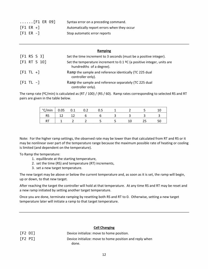
......[F1 ER 09] Syntax error on a preceding command.
[F1 ER +] Automatically report errors when they occur
[F1 ER -] Stop automatic error reports
Ramping
[F1 RS S 3] Set the time increment to 3 seconds (must be a positive integer).
[F1 RT S 10] Set the temperature increment to 0.1 ºC (a positive integer, units are hundredths of a degree).
[F1 TL +] Ramp the sample and reference identically (TC 225 dual controller only).
[F1 TL -] Ramp the sample and reference separately (TC 225 dual controller only).
The ramp rate (ºC/min) is calculated as (RT / 100) / (RS / 60). Ramp rates corresponding to selected RS and RT pairs are given in the table below.
°C/min 0.05 0.1 0.2 0.5 1 2 5 10
RS 12 12 6 6 3 3 3 3
RT 1 2 2 5 5 10 25 50
Note: For the higher ramp settings, the observed rate may be lower than that calculated from RT and RS or it may be nonlinear over part of the temperature range because the maximum possible rate of heating or cooling is limited (and dependent on the temperature).
To Ramp the temperature: 1. equilibrate at the starting temperature, 2. set the time (RS) and temperature (RT) increments, 3. set a new target temperature.
The new target may be above or below the current temperature and, as soon as it is set, the ramp will begin, up or down, to that new target.
After reaching the target the controller will hold at that temperature. At any time RS and RT may be reset and a new ramp initiated by setting another target temperature.
Once you are done, terminate ramping by resetting both RS and RT to 0. Otherwise, setting a new target temperature later will initiate a ramp to that target temperature.
Cell Changing
[F2 DI] Device initialize: move to home position.
[F2 PI] Device initialize: move to home position and reply when done.
13
......[F2 OK] Device is finished moving.
[F2 DL 3] Device locate: move to position 3. (Device must be initialized prior to using this command.)
[F2 PL 6] Device locate: move to position 6 and reply when done.
......[F2 DL 6] Device is now in position 6.
[F2 ?] Report status of device.
......[F2 OK] Device is ready to accept commands.
......[F2 BUSY] Device is busy running commands.
[F2 PL ?] What is the device location (position)?
......[F2 DL 2] Device is in position 2. (If reply is 0, device is not initialized.)
[F2 DD 2] Set speed to 2 (acceptable range 2‐250 with 2 being fast, 250 being slow).
[F2 DD ?] What is the current device speed?
......[F2 DD 2] Device is set to speed setting 2. (If reply is 0, then internal
default value is being used.)
Reference Cuvette
[R1 … ]
To control the temperature of the reference cuvette of a Dual Temperature Controller, use any commands in classes 3‐7, substituting R1 for F1. If you wish to ramp the temperature of the reference and sample cuvettes together, please note the linking command [F1 TL +] in command class 10.
14
Appendix 2: Q‐Blue Program Commands
In addition to the controller commands of Appendix 1, Q‐Blue provides the following functionality.
1. Enables generation of a temperature ramp at a user specified rate.
2. Maintains records of temperature as a function of time for the sample holder and for the thermistor probe (and also for the reference holder for the dual controller). The time interval between time/temperature entries is determined by the user.
3. Saves the time/temperature records to tab‐delimited text files or copies the records to the Windows clipboard.
4. Displays a plot of the time/temperature records singly or together (an example can be found in Appendix 3). The plots can be copied to the Windows clipboard.
5. Has a setting that will notify the user that the holder temperature has been stable for a user specified time. This is useful because the sample temperature always lags behind the holder temperature. This capability is available only if the computer has a speaker.
6. Allows the user to send individual commands or short series of commands to the controller.
7. Permits the user to monitor all communications to and from the controller.
8. Enables the user to send a long series of commands by loading a text file (known as a controller script) that can be easily generated in a text editor such as Windows Notepad.
9. Provides a number of program specific script commands to help manage execution of the script. For example:
A command to delay a specified time before executing the next script command.
Various commands to wait for specified conditions such as holder temperature stability or the completion of a temperature ramp. Once the condition is satisfied, script execution proceeds to the next command.
The following list includes all of the program specific script commands for Q‐Blue.
Delay and Wait commands
[*D #] ‐ Delay # INTERVALS before running the next command. Example: [*D 120] will cause a delay of 120 of the INTERVAL units as defined in the first line of the script (see the example script in Appendix 3 where the second line sets INTERVAL to 0.6 seconds or 0.01 minutes).
[*WRP>=#] ‐ Wait until the ramp parameter exceeds or equals a particular value (# as an integer).
[*WRP<=#] ‐ Wait until the ramp parameter decreases to or below a particular value (# as an integer).
[*WCT>=#] ‐ Wait until the current (holder) temperature exceeds or equals a particular value (# as an integer).
[*WCT<=#] ‐ Wait until the current temperature decreases to or below a particular value (# as an integer).
The current temperature is the temperature of the metal body of the sample cuvette holder.
15
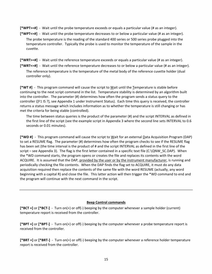
[*WPT>=#] ‐ Wait until the probe temperature exceeds or equals a particular value (# as an integer).
[*WPT<=#] ‐ Wait until the probe temperature decreases to or below a particular value (# as an integer).
The probe temperature is the reading of the standard 400 series or 500 series probe plugged into the temperature controller. Typically the probe is used to monitor the temperature of the sample in the cuvette.
[*WRT>=#] ‐ Wait until the reference temperature exceeds or equals a particular value (# as an integer).
[*WRT<=#] ‐ Wait until the reference temperature decreases to or below a particular value (# as an integer).
The reference temperature is the temperature of the metal body of the reference cuvette holder (dual controller only).
[*WT #] ‐ This program command will cause the script to Wait until the Temperature is stable before continuing to the next script command in the list. Temperature stability is determined by an algorithm built into the controller. The parameter (#) determines how often the program sends a status query to the controller ([F1 IS ?], see Appendix 1 under Instrument Status). Each time this query is received, the controller returns a status message which includes information as to whether the temperature is still changing or has met the criteria for being stable (controlled).
The time between status queries is the product of the parameter (#) and the script INTERVAL as defined in the first line of the script (see the example script in Appendix 3 where the second line sets INTERVAL to 0.6 seconds or 0.01 minutes).
[*WD #] ‐ This program command will cause the script to Wait for an external Data Acquisition Program (DAP) to set a RESUME flag. The parameter (#) determines how often the program checks to see if the RESUME flag has been set (the time interval is the product of # and the script INTERVAL as defined in the first line of the script – see Appendix 3). The flag is the first letter contained in a specific text file (C:\QNW_SC.DAP). When the *WD command starts, the program opens or creates the file and replaces its contents with the word ACQUIRE. It is assumed that the DAP, provided by the user or by the instrument manufacturer, is running and periodically checking the file contents. When the DAP finds the flag set to ACQUIRE, it must do any data acquisition required then replace the contents of the same file with the word RESUME (actually, any word beginning with a capital R) and close the file. This latter action will then trigger the *WD command to end and the program will continue with the next command in the script.
Beep Control commands
[*BCT +] or [*BCT‐] ‐ Turn on(+) or off(‐) beeping by the computer whenever a sample holder (current) temperature report is received from the controller.
[*BPT +] or [*BPT‐] ‐ Turn on(+) or off(‐) beeping by the computer whenever a probe temperature report is received from the controller.
[*BRT +] or [*BRT‐] ‐ Turn on(+) or off(‐) beeping by the computer whenever a reference holder temperature report is received from the controller.
16
Warning Control commands
[*E+] or [*E‐] ‐ When a script is running, attempting to use certain of the buttons or other controls in the main window will cause the appearance of a dialog box asking if you are sure you want to send the associated command (thus changing the series of actions defined by the script). The appearance of this dialog can be avoided at any point in the script by including the program command [*E‐]. Alternatively, the appearance of the warning dialog can be reinstated by including [*E+] at any point in the script.
Listing Control commands
[*LIS +] or [*LIS ‐] ‐ Enable (+) or Disable (‐) listing of Instrument Status replies during running of a script.
[*LER +] or [*LER ‐] ‐ Enable (+) or Disable (‐) listing of Error Message replies during running of a script.
[*LCT +] or [*LCT ‐] ‐ Enable (+) or Disable (‐) listing of Current Temperature replies during running of a script.
[*LPT +] or [*LPT ‐] ‐ Enable (+) or Disable (‐) listing of Probe Temperature replies during running of a script.
[*LRT +] or [*LRT ‐] ‐ Enable (+) or Disable (‐) listing of Reference Temperature replies during running of a script.
These ten program commands can be used to control whether the indicated information, sent from the Serial Controller to the program, are to be listed (displayed) in a script monitoring window while the script is running. Disabling the listings may be useful to make progress of the script clearer since, under some conditions, large numbers of Instrument Status replies and Temperature replies may be generated while the script is running. Disabling affects only the listing of these various replies in the script monitoring window during the running of a script – the temperatures will included in the time/temperature records.
17
Miscellaneous commands
[*R] ‐ This program command is used only at the end of a script. It will cause the script to be repeated, starting at the beginning.
[*P] ‐ If the plot window is displayed while a script is running, the data in the plot will not be automatically updated unless a delay (*D) or wait (*W) command is being processed. This program command will cause the plot window to update (replot to show all data collected to that time).
[*CTD] ‐ This command will clear the time/temperature records. In addition, the time will be restarted at zero and a new record of time/temperature will be started.
[*MSG + message] or [*MSG ‐ message] ‐ This command will stop execution of the script and present a dialog box containing the second command parameter ("message"). Change this parameter to the wording you want the dialog box to display. The first parameter (+ or ‐) determines whether the computer beeps (+) or not (‐) while the dialog box is visible. When the user clicks the "OK" button the dialog box closes and execution of the script continues.
18
Appendix 3: Example Script: Temperature Ramping
The following is an example of a script file. Scripts may be used to automate complex functions such as the three‐old ramping illustrated here. Any text that is not enclosed by square brackets ( [ ] ) is completely ignored by the script processor, permitting the extensive commenting. When this script was executed by the QNW Serial Control program (described in Appendix 2) the time/temperature data in the plot that follows the script listing was obtained.
Controller Script
Interval = .6 Set the time interval between commands to .6 seconds.
------------------
Initial Setup
------------------
[*E-] Prevent appearance of a warning dialog that may block script
execution if a main window button or control is used.
[F1 PX +] Display probe temperature to 0.01 °C precision.
[F1 TT S 10.00] Set Target Temperature to 10 °C.
[F1 TC +] Turn on Temperature Control.
[F1 CT +30] Report current cuvette holder temperature periodically.
[F1 PT +30] Report probe temperature periodically.
[*LTT -] Do not list target temperature returns in script window.
[*LCT -] Do not list current temperature returns in script window.
[*LPT -] Do not list probe temperature returns in script window.
[*MSG - This script requires pre-equilibration to 10 °C. Click OK when satisfactory equilibration has been achieved]
Waits for the user to respond
[*CTD] Clear time/temperature displays and reset time to zero
[*D=500] Collect temperatures for 5 minutes.
------------------
First Ramp to 40 at 4 °C/min:
------------------
[F1 RT S 40] Set Ramping Temperature Interval to 0.40 °C.
[F1 RS S 6] Set Ramping Time Interval to 6 seconds.
Ramping rate will be 4 °C/min (0.4 °C/ 0.1 min).
[F1 PT -] Stop reporting probe temperature periodically.
[F1 PA +] Turn on Automatic Probe temperature report
[F1 PA S 2.0] Set Automatic Probe temperature report to every 2.0 °C.
[*BPT +] Turn on the option for computer to beep each time a probe
temperature report is received.
[F1 TT S 40.00] Set Target Temperature to 40 °C, to start ramping process.
[*WRP>=40] Wait until the ramp parameter reaches 40 °C.
------------------
Second Ramp to 45 at 0.2 °C/min:
------------------
[F1 RT S 4] Set Ramping Temperature Interval to .04 °C.
[F1 RS S 12] Set Ramping Time Interval to 12 seconds.
19
Ramping rate will be 0.2 °C/min (0.04 °C/ 0.2 min).
[F1 PA S 0.5] Set Automatic Probe temperature report to every 0.5 °C.
[F1 TT S 45.00] Set Target Temperature to 45 °C to start ramping process.
[*WRP>=45] Wait until the ramp parameter reaches 45 °C.
[*D 200] Wait 2 minutes for probe temperature to catch up.
------------------
Third Ramp to 80:
------------------
[F1 RT S 40] Set Ramping Temperature Interval to .40 °C
[F1 RS S 6] Set Ramping Time Interval to 6 seconds
Ramping rate will be 4 °C/min.
[F1 PA S 2.0] Set Automatic Probe temperature report to every 2.0 °C.
[F1 TT S 80.00] Set Target Temperature to 80 °C to start ramping process.
[*WRP>=80] Wait until the ramp parameter reaches 80 °C.
[*D 300] Wait 3 minutes to allow the probe temperature to catch up
[F1 PA -] Stop automatic probe temperature reporting
[F1 PT +30] Start periodic probe temperature reporting
(current temperature reporting is already running)
[*BPT -] Turn off the computer beep each time a probe
temperature report is received.
[*D 800] Wait 8 min to allow temperatures to stabilize.
------------------
Ramp back to 20:
------------------
[F1 RT S 25] Set Ramping Temperature Interval to .25 °C.
[F1 RS S 6] Set Ramping Time Interval to 6 seconds.
Ramping rate will be 2.5 °C per minute.
[F1 PT -] Stop periodic probe temperature reporting.
[F1 PA +] Turn on Automatic Probe temperature report.
[F1 PA S 5.0] Set Automatic Probe report to every 5.0 °C.
[F1 TT S 20.00] Set Target Temperature to 20 °C to start ramping process.
[*WRP<=20] Wait until the ramp parameter reaches 20 °C.
[*D 300] Hold 3 minutes to allow the probe temperature to catch up.
------------------
Clean up
------------------
[F1 RT S 0] Stop ramping. (If this is not done, the next target temperature
[F1 RS S 0] that is set will generate a ramp using the previous settings.)
[F1 PA -] Stop automatic probe temperature reporting.
[F1 PT +30] Start periodic probe temperature reporting.
(Current temperature reporting is already running.)
[*D 700] Wait another 7 minutes for final equilibration.
20
[F1 PT -] Stop periodic probe temperature reporting.
[F1 CT -] Stop periodic sample holder temperature reporting.
[*E+] Enable appearance of a warning dialog if a main window button
or control is used while a script is running.
[F1 PX -] Reset display of probe temperature to 0.1 °C precision.
[*MSG + The multiramp script run is complete]
Notify user, with beeping.
The script sets a target temperature of 10 degrees and then turns temperature control on and waits until the user is satisfied with the state of equilibration. During this time the probe temperature is reported every 30 seconds (the sample holder temperature is reported every 30 seconds throughout the run). The script then initiates the first ramp from 10 to 40 degrees at 4 degrees/min with the computer beeping each time a probe temperature is reported at 2 degree intervals. The second ramp from 40 to 45 degrees is slower (0.2 degrees/min), with the computer beeping every 0.5 degrees (to provide more information over a critical range of temperatures). The third ramp takes the temperature quickly to 80 degrees, again with beeping at 2 degree intervals. At this point beeping is stopped and an 8 minute delay of script execution allows time for equilibration at 80 degrees; the probe temperature is reported every 30 seconds. The final ramp is down to 20 degrees at 2.5 degrees/min with probe temperature reports every 5 degrees. This is followed by a 7 minute delay for equilibration with automatic probe temperature reports every 30 seconds. Figure 1 shows a typical example of the sample holder and probe temperatures as a function of time.
Actual data obtained by running the example script in the QNW Serial Control Program (V2.3). The sample holder temperatures are plotted as a solid line without tokens; the probe temperatures are shown as filled circles connected by a line.
21
This multi‐ramp script would be useful if a researcher were monitoring fluorescence intensity or absorbance of a sample showing a sharp melting transition near 42 °C. By recording the time and signal amplitude each time the probe temperature was reported (each time the computer beeped, between 5 min and 50 min in Figure 1) and correlating those time/amplitude pairs with the time/temperature pairs reported by the QNW Serial Control program, a plot of signal amplitude vs time could be generated. The plot below is a simulation of such a result.
Of course, it would be optimal if the sample temperature and the measured parameter could be automatically obtained simultaneously. However, that requires that temperature monitoring and parameter acquisition be done by the same program. Lacking that, then one would like to be able to acquire temperature and parameter data at the same time interval with both acquisition processes started at as close to the same time as possible.
An example of this latter procedure is given in Figure 3 which shows experimental data obtained for the melting transition of the synthetic alternating copolymer of deoxyadenosine and deoxythymidine, poly(dA‐dT) using a simple temperature ramp script. The absorbance data were obtained using a fiber‐optic spectrometer,
light source and software in combination with a QNW qpod 2e® fiber‐optic sample holder and the QNW Serial Control program. The temperature ramp and absorbance data collections were started “simultaneously” using a timing interval of 0.1 minute.
Figure 2. Simulated melting data that might be measured
22
Figure 3. Experimental data obtained for the melting transition of the synthetic alternating copolymer of deoxyadenosine and deoxythymidine, poly(dA‐dT) using a linear temperature ramp. Data are shown for the copolymer alone (black) and for the copolymer in the presence of ethidium (gray). Panel A shows the temperature as a function of time. Panel B shows the average absorbance as a function of time. Panel C combines the data in A and B to show the change in the average absorbance as a function of temperature.