19
ARL-TN-1024 ● AUG 2020 Quadrature Decoder Design Using Microcontroller On-Chip Configurable Logic by Michael Don and Mark Ilg Approved for public release; distribution is unlimited.
ARL-TN-1024 ● AUG 2020
Quadrature Decoder Design Using Microcontroller On-Chip Configurable Logic by Michael Don and Mark Ilg Approved for public release; distribution is unlimited.

NOTICES
Disclaimers
The findings in this report are not to be construed as an official Department of the Army position unless so designated by other authorized documents. Citation of manufacturer’s or trade names does not constitute an official endorsement or approval of the use thereof. Destroy this report when it is no longer needed. Do not return it to the originator.

ARL-TN-1024 ● AUG 2020
Quadrature Decoder Design Using Microcontroller On-Chip Configurable Logic Michael Don and Mark Ilg Weapons and Materials Research Directorate, CCDC Army Research Laboratory Approved for public release; distribution is unlimited.
ii
REPORT DOCUMENTATION PAGE Form Approved OMB No. 0704-0188
Public reporting burden for this collection of information is estimated to average 1 hour per response, including the time for reviewing instructions, searching existing data sources, gathering and maintaining the data needed, and completing and reviewing the collection information. Send comments regarding this burden estimate or any other aspect of this collection of information, including suggestions for reducing the burden, to Department of Defense, Washington Headquarters Services, Directorate for Information Operations and Reports (0704-0188), 1215 Jefferson Davis Highway, Suite 1204, Arlington, VA 22202-4302. Respondents should be aware that notwithstanding any other provision of law, no person shall be subject to any penalty for failing to comply with a collection of information if it does not display a currently valid OMB control number. PLEASE DO NOT RETURN YOUR FORM TO THE ABOVE ADDRESS.
1. REPORT DATE (DD-MM-YYYY)
August 2020 2. REPORT TYPE
Technical Note 3. DATES COVERED (From - To)
1–30 February 2020 4. TITLE AND SUBTITLE
Quadrature Decoder Design Using Microcontroller On-Chip Configurable Logic
5a. CONTRACT NUMBER
5b. GRANT NUMBER
5c. PROGRAM ELEMENT NUMBER
6. AUTHOR(S)
Michael Don and Mark Ilg 5d. PROJECT NUMBER
5e. TASK NUMBER
5f. WORK UNIT NUMBER
7. PERFORMING ORGANIZATION NAME(S) AND ADDRESS(ES)
CCDC Army Research Laboratory ATTN: FCDD-RLW-LF Aberdeen Proving Ground, MD 21005
8. PERFORMING ORGANIZATION REPORT NUMBER
ARL-TN-1024
9. SPONSORING/MONITORING AGENCY NAME(S) AND ADDRESS(ES)
10. SPONSOR/MONITOR'S ACRONYM(S)
11. SPONSOR/MONITOR'S REPORT NUMBER(S)
12. DISTRIBUTION/AVAILABILITY STATEMENT
Approved for public release; distribution is unlimited. 13. SUPPLEMENTARY NOTES ORCID ID(s): Michael Don, 0000-0002-8021-9066
14. ABSTRACT
The US Army Combat Capabilities Development Command (CCDC) Army Research Laboratory has developed a highly maneuverable airframe for long-range precision munitions research. This new design requires four quadrature encoders, more than the number available on the real-time microcontroller CCDC Army Research Laboratory employs for actuator control. Texas Instruments’ configurable logic block was used to provide a low-cost, elegant solution using on-chip configurable logic to construct an additional decoder. In addition, since microcontroller on-chip configurable logic is relatively new and outside the scope of typical microcontroller-programming expertise, this note serves as a valuable example for future designs.
15. SUBJECT TERMS
real-time microcontrollers, rotary encoders, configurable logic, quadrature decoder, microcontroller peripherals
16. SECURITY CLASSIFICATION OF: 17. LIMITATION OF ABSTRACT
UU
18. NUMBER OF PAGES
19
19a. NAME OF RESPONSIBLE PERSON
Michael Don a. REPORT
Unclassified b. ABSTRACT
Unclassified
c. THIS PAGE
Unclassified
19b. TELEPHONE NUMBER (Include area code)
410-306-0775 Standard Form 298 (Rev. 8/98)
Prescribed by ANSI Std. Z39.18
iii
Contents
List of Figures iv
List of Tables iv
1. Introduction 1
2. Quadrature Encoding 1
3. VHDL Design 2
4. TI CLB Design 4
5. Conclusion 5
6. References 6
Appendix. Very High Speed Integrated Circuit Hardware Description Language (VHDL) Files 8
List of Symbols, Abbreviations, and Acronyms 12
Distribution List 13
iv
List of Figures
Fig. 1 Quadrature encoder operation ............................................................... 2
Fig. 2 VHDL quadrature decoder diagram ...................................................... 3
Fig. 3 Quadrature encoder simulation ............................................................. 3
Fig. 4 CLB quadrature decoder diagram ......................................................... 5
Fig. 5 CLB logic simulation ............................................................................ 5
Fig. 6 VHDL logic simulation......................................................................... 5
List of Tables
Table 1. Direction signal logic ............................................................................ 4
1
1. Introduction
The US Army Combat Capabilities Development Command (CCDC) Army Research Laboratory (ARL) has developed a high-maneuverability airframe (HMA) in support of the long-range precision fires’ modernization priority.1 Prior research explored under-actuated solutions with reduced actuator requirements that dithered canards in phase with projectile rotation.2 In order to increase maneuverability, HMA uses four independent actuators, requiring four independent quadrature decoders. This presents a problem. The Texas Instruments (TI) C2000 microcontroller family that the CCDC Army Research Laboratory uses for real-time control possesses a maximum of three decoders.3 So, what is the simplest, most cost-effective way to add an extra decoder to the system?
The solution is to use a powerful capability that has been added to several microcontroller families in recent years: on-chip configurable logic.4–6 TI’s configurable logic block (CLB) can implement custom logic and augment existing peripherals like pulse-width modulators, quadrature encoders, and general-purpose input/outputs (GPIO), eliminating external programmable logic components. Even though there has been a long history of combining processors and programmable logic on a single chip,7,8 current products that augment the functionality of mainstream microcontrollers using programmable logic are relatively new and not well documented. In addition, the custom digital-design capabilities offered by configurable logic are outside the purview of typical microcontroller-programmer expertise. This makes it difficult to find advice and examples from standard resources that are usually extremely helpful when attempting to utilize new microcontroller functionality. Thus, besides providing an elegant, low-cost solution for HMA’s hardware requirements, this technical note is also important as an example of adding complex functionality to a microcontroller using on-chip configurable logic.
This note is organized as follows. First, the concept of quadrature encoding is explained. Next, the Very High Speed Integrated Circuit Hardware Description Language (VHDL) decoder design is presented. Finally, the decoder implementation using TI’s CLB is described.
2. Quadrature Encoding
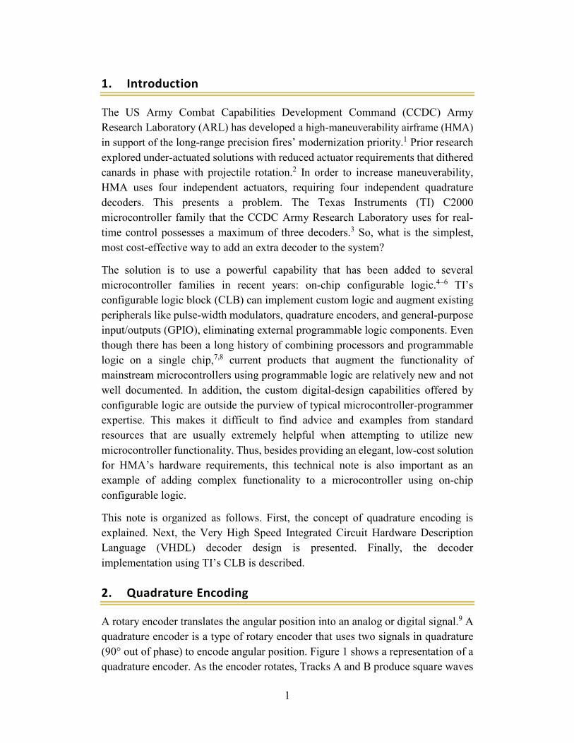
A rotary encoder translates the angular position into an analog or digital signal.9 A quadrature encoder is a type of rotary encoder that uses two signals in quadrature (90° out of phase) to encode angular position. Figure 1 shows a representation of a quadrature encoder. As the encoder rotates, Tracks A and B produce square waves
2
90° out of phase. Channel A leads Channel B when the shaft rotates clockwise, and Channel B leads Channel A when the rotation is counterclockwise.
Fig. 1 Quadrature encoder operation
3. VHDL Design
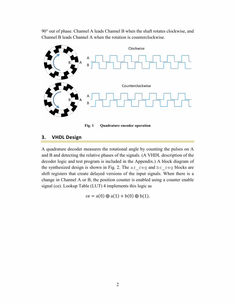
A quadrature decoder measures the rotational angle by counting the pulses on A and B and detecting the relative phases of the signals. (A VHDL description of the decoder logic and test program is included in the Appendix.) A block diagram of the synthesized design is shown in Fig. 2. The ar_reg and br_reg blocks are shift registers that create delayed versions of the input signals. When there is a change in Channel A or B, the position counter is enabled using a counter enable signal (ce). Lookup Table (LUT) 4 implements this logic as
ce = a(0) ⨁ a(1) + b(0) ⨁ b(1).
3
Fig. 2 VHDL quadrature decoder diagram
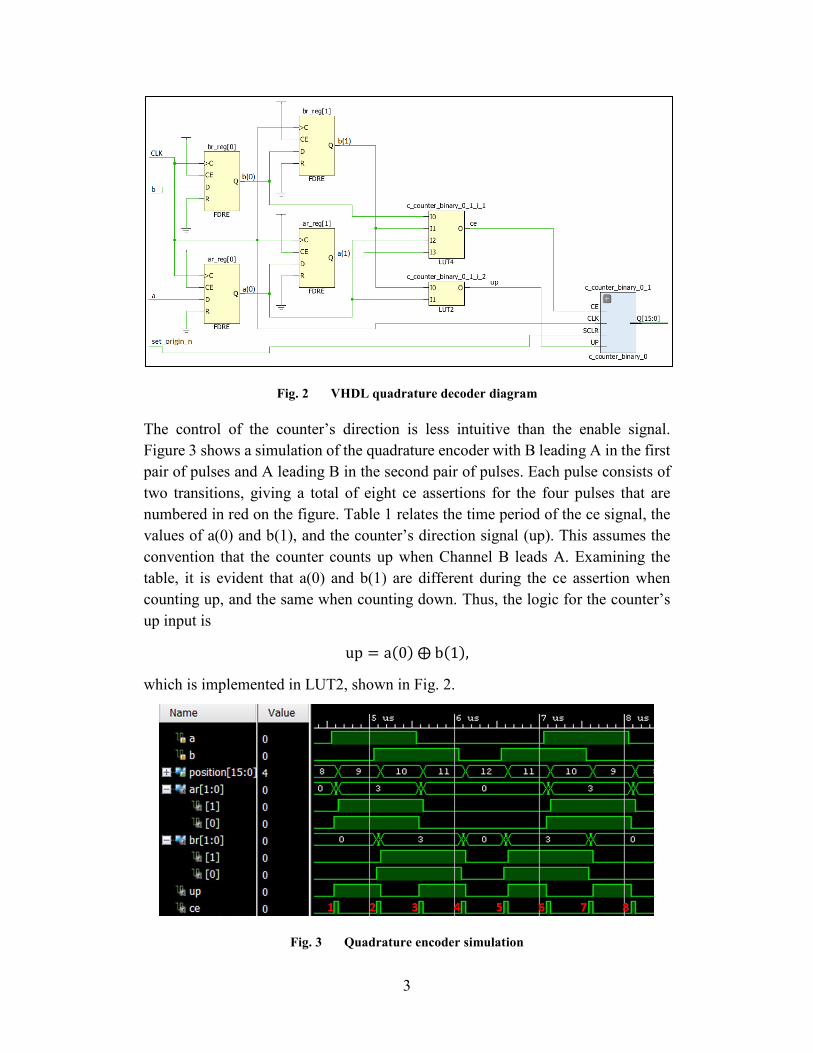
The control of the counter’s direction is less intuitive than the enable signal. Figure 3 shows a simulation of the quadrature encoder with B leading A in the first pair of pulses and A leading B in the second pair of pulses. Each pulse consists of two transitions, giving a total of eight ce assertions for the four pulses that are numbered in red on the figure. Table 1 relates the time period of the ce signal, the values of a(0) and b(1), and the counter’s direction signal (up). This assumes the convention that the counter counts up when Channel B leads A. Examining the table, it is evident that a(0) and b(1) are different during the ce assertion when counting up, and the same when counting down. Thus, the logic for the counter’s up input is
up = a(0) ⨁ b(1),
which is implemented in LUT2, shown in Fig. 2.
Fig. 3 Quadrature encoder simulation
4
Table 1. Direction signal logic
ce number a(0) b(1) Direction 1 1 0 up 2 1 0 up 3 0 1 up 4 0 1 up 5 0 0 down 6 1 1 down 7 1 1 down 8 0 0 down
4. TI CLB Design
TI’s C2000 series microcontrollers have four CLB tiles, each consisting of eight inputs, three LUT4s, three finite-state machine (FSM) blocks, three counters, eight LUT3s, and a high-level controller (HLC).10 Inputs can be chosen from GPIOs, peripherals, central processor unit (CPU) signals, or other tiles. Outputs can be sent to GPIOs or other tiles. The HLC provides an interface between the CLB and CPU memory.
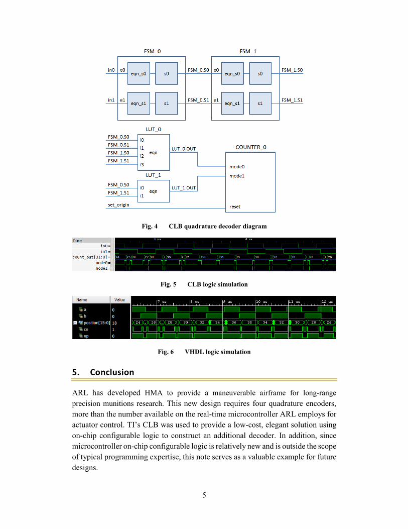
Figure 4 shows a block diagram of the CLB implementation of the quadrature decoder, which mirrors the VHDL design in Fig. 2. The in0 and in1 are Channels A and B, respectively. Each FSM has contains two registers. Two FSMs are connected together to create the input shift registers for Channels A and B. The next state logic simply passes through the input signals (i.e. eqn_s0 = e0 and eqn_s1 = e1) for both FSM_0 and FSM_1. The LUT_0.OUT is the ce signal and LUT_1.OUT is the up indicator, giving
LUT_0. OUT = i0 ⨁ i1 + i2 ⨁ i3.
and LUT_1. OUT = i0 ⨁ i1.
The value of the counter can be accessed by the processor through the HLC.
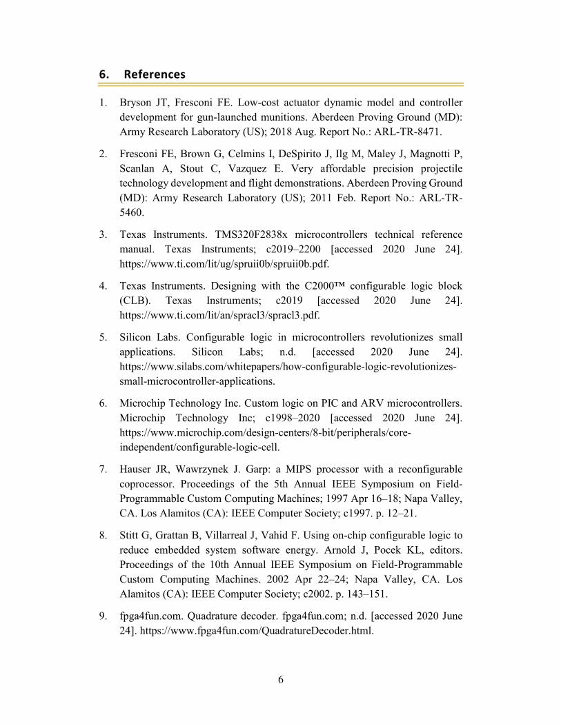
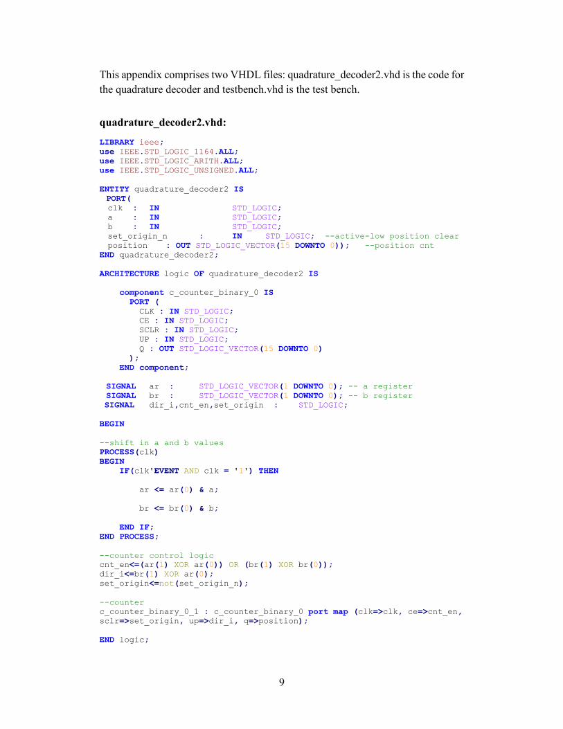
CLB simulation with custom input signals is undocumented, but square wave inputs can be easily configured. Figure 5 shows a simulation using a square wave with 9 cycles high and 10 cycles low as in0, and 10 cycles high and 10 low as in1. The difference in frequencies gradually causes the phases to shift from in1 leading in0 to in0 leading in1, causing a change in the up signal. An analogous simulation shown in Fig. 6 was performed in VHDL. The results are the same as the CLB simulation, verifying the CLB logic design. VHDL test source code is included in the Appendix.
5
Fig. 4 CLB quadrature decoder diagram
Fig. 5 CLB logic simulation
Fig. 6 VHDL logic simulation
5. Conclusion
ARL has developed HMA to provide a maneuverable airframe for long-range precision munitions research. This new design requires four quadrature encoders, more than the number available on the real-time microcontroller ARL employs for actuator control. TI’s CLB was used to provide a low-cost, elegant solution using on-chip configurable logic to construct an additional decoder. In addition, since microcontroller on-chip configurable logic is relatively new and is outside the scope of typical programming expertise, this note serves as a valuable example for future designs.
6
6. References
1. Bryson JT, Fresconi FE. Low-cost actuator dynamic model and controller development for gun-launched munitions. Aberdeen Proving Ground (MD): Army Research Laboratory (US); 2018 Aug. Report No.: ARL-TR-8471.
2. Fresconi FE, Brown G, Celmins I, DeSpirito J, Ilg M, Maley J, Magnotti P, Scanlan A, Stout C, Vazquez E. Very affordable precision projectile technology development and flight demonstrations. Aberdeen Proving Ground (MD): Army Research Laboratory (US); 2011 Feb. Report No.: ARL-TR-5460.
3. Texas Instruments. TMS320F2838x microcontrollers technical reference manual. Texas Instruments; c2019–2200 [accessed 2020 June 24]. https://www.ti.com/lit/ug/spruii0b/spruii0b.pdf.
4. Texas Instruments. Designing with the C2000™ configurable logic block (CLB). Texas Instruments; c2019 [accessed 2020 June 24]. https://www.ti.com/lit/an/spracl3/spracl3.pdf.
5. Silicon Labs. Configurable logic in microcontrollers revolutionizes small applications. Silicon Labs; n.d. [accessed 2020 June 24]. https://www.silabs.com/whitepapers/how-configurable-logic-revolutionizes-small-microcontroller-applications.
6. Microchip Technology Inc. Custom logic on PIC and ARV microcontrollers. Microchip Technology Inc; c1998–2020 [accessed 2020 June 24]. https://www.microchip.com/design-centers/8-bit/peripherals/core-independent/configurable-logic-cell.
7. Hauser JR, Wawrzynek J. Garp: a MIPS processor with a reconfigurable coprocessor. Proceedings of the 5th Annual IEEE Symposium on Field-Programmable Custom Computing Machines; 1997 Apr 16–18; Napa Valley, CA. Los Alamitos (CA): IEEE Computer Society; c1997. p. 12–21.
8. Stitt G, Grattan B, Villarreal J, Vahid F. Using on-chip configurable logic to reduce embedded system software energy. Arnold J, Pocek KL, editors. Proceedings of the 10th Annual IEEE Symposium on Field-Programmable Custom Computing Machines. 2002 Apr 22–24; Napa Valley, CA. Los Alamitos (CA): IEEE Computer Society; c2002. p. 143–151.
9. fpga4fun.com. Quadrature decoder. fpga4fun.com; n.d. [accessed 2020 June 24]. https://www.fpga4fun.com/QuadratureDecoder.html.

7
10. Texas Instruments. How to migrate custom logic from an FPGA/CPLD to C2000 microcontrollers. Texas Instruments; n.d. [accessed 2020 June 24]. https://www.ti.com/lit/an/spraco2/spraco2.pdf.

8
Appendix. Very High Speed Integrated Circuit Hardware Description Language (VHDL) Files
9
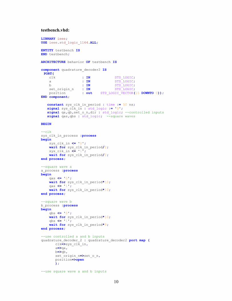
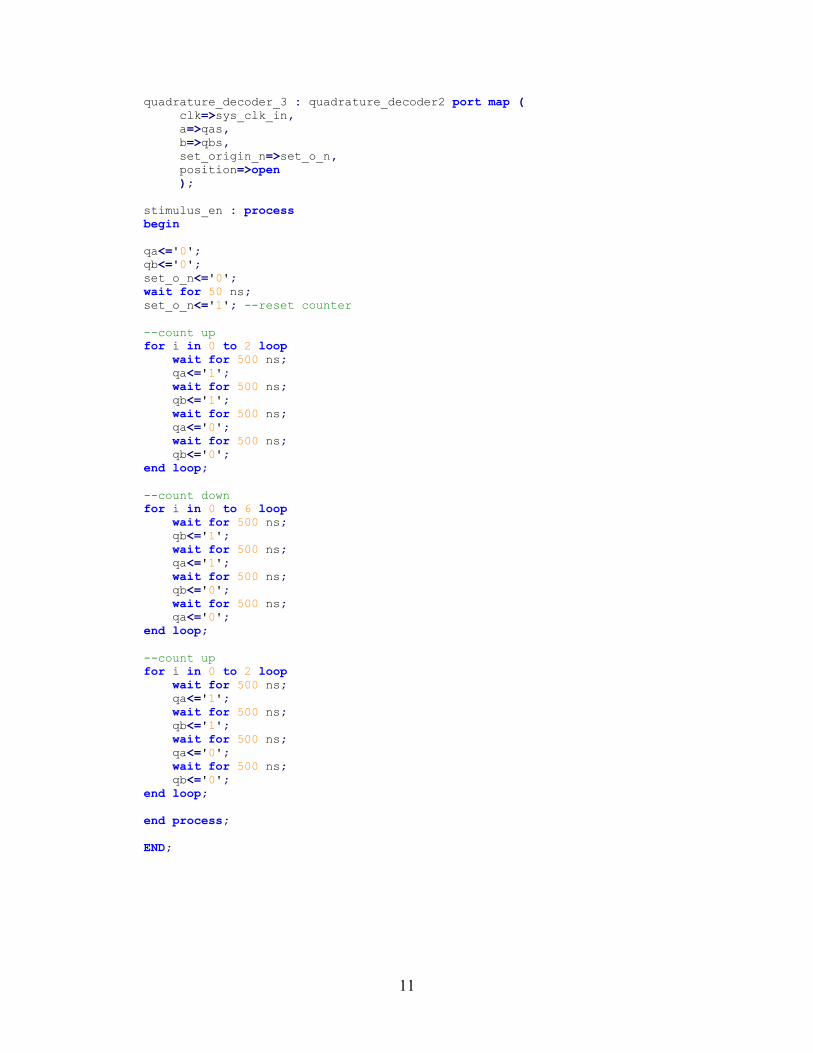
This appendix comprises two VHDL files: quadrature_decoder2.vhd is the code for the quadrature decoder and testbench.vhd is the test bench.
quadrature_decoder2.vhd: LIBRARY ieee; use IEEE.STD_LOGIC_1164.ALL; use IEEE.STD_LOGIC_ARITH.ALL; use IEEE.STD_LOGIC_UNSIGNED.ALL; ENTITY quadrature_decoder2 IS PORT( clk : IN STD_LOGIC; a : IN STD_LOGIC; b : IN STD_LOGIC; set_origin_n : IN STD_LOGIC; --active-low position clear position : OUT STD_LOGIC_VECTOR(15 DOWNTO 0)); --position cnt END quadrature_decoder2; ARCHITECTURE logic OF quadrature_decoder2 IS component c_counter_binary_0 IS PORT ( CLK : IN STD_LOGIC; CE : IN STD_LOGIC; SCLR : IN STD_LOGIC; UP : IN STD_LOGIC; Q : OUT STD_LOGIC_VECTOR(15 DOWNTO 0) ); END component; SIGNAL ar : STD_LOGIC_VECTOR(1 DOWNTO 0); -- a register SIGNAL br : STD_LOGIC_VECTOR(1 DOWNTO 0); -- b register SIGNAL dir_i,cnt_en,set_origin : STD_LOGIC; BEGIN --shift in a and b values PROCESS(clk) BEGIN IF(clk'EVENT AND clk = '1') THEN ar <= ar(0) & a; br <= br(0) & b; END IF; END PROCESS; --counter control logic cnt_en<=(ar(1) XOR ar(0)) OR (br(1) XOR br(0)); dir_i<=br(1) XOR ar(0); set_origin<=not(set_origin_n); --counter c_counter_binary_0_1 : c_counter_binary_0 port map (clk=>clk, ce=>cnt_en, sclr=>set_origin, up=>dir_i, q=>position); END logic;
10
testbench.vhd: LIBRARY ieee; USE ieee.std_logic_1164.ALL; ENTITY testbench IS END testbench; ARCHITECTURE behavior OF testbench IS component quadrature_decoder2 IS PORT( clk : IN STD_LOGIC; a : IN STD_LOGIC; b : IN STD_LOGIC; set_origin_n : IN STD_LOGIC; position : out STD_LOGIC_VECTOR(15 DOWNTO 0)); END component; constant sys_clk_in_period : time := 50 ns; signal sys_clk_in : std_logic := '0'; signal qa,qb,set_o_n,dir : std_logic; --controlled inputs signal qas,qbs : std_logic; --square waves BEGIN --clk sys_clk_in_process :process begin sys_clk_in <= '0'; wait for sys_clk_in_period/2; sys_clk_in <= '1'; wait for sys_clk_in_period/2; end process; --square wave a a_process :process begin qas <= '0'; wait for sys_clk_in_period*10; qas <= '1'; wait for sys_clk_in_period*10; end process; --square wave b b_process :process begin qbs <= '0'; wait for sys_clk_in_period*10; qbs <= '1'; wait for sys_clk_in_period*9; end process; --use controlled a and b inputs quadrature_decoder_2 : quadrature_decoder2 port map ( clk=>sys_clk_in, a=>qa, b=>qb, set_origin_n=>set_o_n, position=>open ); --use square wave a and b inputs
11
quadrature_decoder_3 : quadrature_decoder2 port map ( clk=>sys_clk_in, a=>qas, b=>qbs, set_origin_n=>set_o_n, position=>open ); stimulus_en : process begin qa<='0'; qb<='0'; set_o_n<='0'; wait for 50 ns; set_o_n<='1'; --reset counter --count up for i in 0 to 2 loop wait for 500 ns; qa<='1'; wait for 500 ns; qb<='1'; wait for 500 ns; qa<='0'; wait for 500 ns; qb<='0'; end loop; --count down for i in 0 to 6 loop wait for 500 ns; qb<='1'; wait for 500 ns; qa<='1'; wait for 500 ns; qb<='0'; wait for 500 ns; qa<='0'; end loop; --count up for i in 0 to 2 loop wait for 500 ns; qa<='1'; wait for 500 ns; qb<='1'; wait for 500 ns; qa<='0'; wait for 500 ns; qb<='0'; end loop; end process; END;
12
List of Symbols, Abbreviations, and Acronyms
ARL Army Research Laboratory
CCDC US Army Combat Capabilities Development Command
CLB configurable logic block
CPU central processing unit
FSM finite-state machine
GPIO general-purpose input/output
HLC high-level controller
HMA high-maneuverability airframe
LUT lookup table
TI Texas Instruments
VHDL Very High Speed Integrated Circuit Hardware Description Language

13
1 DEFENSE TECHNICAL (PDF) INFORMATION CTR DTIC OCA 1 CCDC ARL (PDF) FCDD RLD CL TECH LIB 24 CCDC ARL (PDF) FCDD RLW LF
B ALLIK B J ACKER T G BROWN S BUGGS E BUKOWSKI J COLLINS J CONDON B DAVIS M DON D EVERSON M GRABNER R HALL J HALLAMEYER M HAMAOUI T HARKINS M ILG B KLINE J MALEY C MILLER B NELSON D PETRICK K PUGH N SCHOMER B TOPPER


![AN2972, Using the PMSM Vector Control eTPU Function - … · 2019-11-07 · theta - Angle value, in [rad/pi], range (–1, 1) qd_pc - Position counter value from quadrature decoder,](https://static.documents.pub/doc/80x56/5e711344c6d47330107021f1/an2972-using-the-pmsm-vector-control-etpu-function-2019-11-07-theta-angle.jpg)


