Quadrilateral Mesh Generation using Hierarchical Templates Antonio Carlos de Oliveira Miranda 1 and Luiz Fernando Martha 2 1 Department of Civil and Environmental Engineering, University of Braslia, SG-12 Building, Darcy Ribeiro Campus, DF, 70.910-900, Brazil [email protected]2 Department of Civil Engineering, Pontifical Catholic University of Rio de Janeiro, Rua Marqus de So Vicente 225, Gvea, Rio de Janeiro, RJ, 22453-900, Brazil [email protected]Abstract: This paper describes a quadrilateral mesh generation algorithm ide- ally suited for transition subdomain meshes in the context of any domain de- composition meshing strategy. The algorithm is based on an automatic hierar- chical region decomposition in which, in the last level, it is possible to generate quadrilateral elements with a conventional mapping strategy. In two dimen- sions, a subdomain is usually a triangle or a rectangle. In this algorithm, a subdomain with two boundary curves may also be allowed. Templates impose restrictions on the number of boundary curve segments of a subdomain to be meshed. The proposed hierarchical template scheme eliminates these restric- tions, requiring only an even number of boundary segments. Other algorithms in the literature present similar characteristics. However, the implementation of the hierarchical decomposition and its templates presented here is quite simple compared to other approaches. Six high-level templates are considered for a subdomain, depending on the number of boundary curves and the num- ber of segments on each curve. Several examples demonstrate that this simple idea may result in structured meshes of surprisingly good quality. We also show the possibility of obtaining different meshes for a subdomain with fixed boundary discretization by changing the corners between curves. Keywords: template-based mesh; structured quadrilateral mesh; domain decomposition; mapping, transition mesh 1 Introduction This paper describes a novel hierarchical template-based meshing scheme for generating good-quality quadrilateral meshes. This approach is ideally suited for transition subdomain meshes in the context of structured 2D or surface meshing strategies, such as mapping, submapping, sweeping, medial axis,
Antonio Carlos de Oliveira Miranda1 and Luiz Fernando Martha2
1 Department of Civil and Environmental Engineering, University of Braslia,SG-12 Building, Darcy Ribeiro Campus, DF, 70.910-900, [email protected]
2 Department of Civil Engineering, Pontifical Catholic University of Rio deJaneiro, Rua Marqus de So Vicente 225, Gvea, Rio de Janeiro, RJ, 22453-900,Brazil [email protected]
Abstract: This paper describes a quadrilateral mesh generation algorithm ide-ally suited for transition subdomain meshes in the context of any domain de-composition meshing strategy. The algorithm is based on an automatic hierar-chical region decomposition in which, in the last level, it is possible to generatequadrilateral elements with a conventional mapping strategy. In two dimen-sions, a subdomain is usually a triangle or a rectangle. In this algorithm, asubdomain with two boundary curves may also be allowed. Templates imposerestrictions on the number of boundary curve segments of a subdomain to bemeshed. The proposed hierarchical template scheme eliminates these restric-tions, requiring only an even number of boundary segments. Other algorithmsin the literature present similar characteristics. However, the implementationof the hierarchical decomposition and its templates presented here is quitesimple compared to other approaches. Six high-level templates are consideredfor a subdomain, depending on the number of boundary curves and the num-ber of segments on each curve. Several examples demonstrate that this simpleidea may result in structured meshes of surprisingly good quality. We alsoshow the possibility of obtaining different meshes for a subdomain with fixedboundary discretization by changing the corners between curves.
This paper describes a novel hierarchical template-based meshing scheme forgenerating good-quality quadrilateral meshes. This approach is ideally suitedfor transition subdomain meshes in the context of structured 2D or surfacemeshing strategies, such as mapping, submapping, sweeping, medial axis,
2 Antonio Carlos de Oliveira Miranda and Luiz Fernando Martha
auto-decomposition or user-assisted decomposition. One of the main draw-backs of these meshing schemes is the constraint on the number of subdomainboundary curve segments. For quadrilateral subdomains, the number of seg-ments on opposite boundary curves must be equal, and, for triangular subdo-mains, the three boundary curves must have equal number of segments. In thisenvironment, it is difficult to implement local mesh refinement without usingnon-structured hybrid subdomain meshes because any change in the numberof segments of a boundary curve forces the propagation of this modification toopposite subdomain curves. The proposed hierarchical template-based mesh-ing scheme produces quad-mapping transition meshes without any constrainton the number of boundary segments. The only requirement is that the totalnumber of segments must be even, which is a general rule for any quadrilateralmesh [?, ?].
In the context of quadrilateral mesh generation, template is a pattern thatdescribes how a single polygon can be decomposed into quadrilaterals. In twodimensions or in surface meshing, a single polygon is usually a triangle or arectangle. Many finite element meshing algorithms use templates to some de-gree. For example, mapping techniques may be considered as simple templates.Initially, classical structured mapping strategies [?] were proposed, defininggeneralized curvilinear coordinate systems for closed, bounded and simplyconnected domains on the plane or in 3D surfaces. A similar approach wasproposed in another work [?] for generated hexahedral meshes using body-oriented coordinates defined by three-dimensional regions bounded by sixsurfaces. In both works, transfinite mapping techniques were established forcurvilinear coordinate systems in arbitrary domains to approximate complexsurfaces and volumes. Haber et al. [?] and Haber and Abel [?] used transfinitemappings based on discrete boundary curves, and applied these techniques totwo-dimensional and three-dimensional surface preprocessing programs. Thisdiscrete form of the mapping allows representing boundary geometries gener-ically. The basic idea of these works is to use triangular and quadrilateraltemplate meshes in a parametric space and map them to Cartesian space.Similar ideas were developed to generate three-dimensional meshes [?, ?]. It isinteresting to observe that, in 1982, Cook and Oakes [?] presented examplesof quadrilateral mesh grading algorithms for gradual or rapid element densitytransitions, but the algorithms were not formalized. Similar techniques werecited by Thompson [?].
Another meshing technique that employs templates is recursive domainsubdivision using quadtree [?]. Yerry and Shephard [?] pioneered this tech-nique, proposing templates to generate triangular and quadrilateral elements.Other works have been published following similar ideas with some improve-ments and modifications [?, ?, ?, ?]. In general, this mesh generation processis implemented in three stages. Initially, the domain’s interior is filled witha quadtree that is recursively and locally refined according to given bound-ary refinement information. Care is taken to avoid adjacent quadtree cellsthat have a difference of more than one in tree depth. Then, templates that
Quadrilateral Mesh Generation using Hierarchical Templates 3
depend on cell adjacency are employed to mesh the interior cells. In a finalstage, the region between the interior mesh and the boundary is also meshedusing several meshing schemes, which might employ other types of templates.A recent work [?] describes a template scheme for meshing all quadrilateralelements with guaranteed quality while preserving features of the boundary.Analogous procedures are used for three-dimensional mesh generation usingan octree [?, ?, ?, ?]. Schneiders et al. [?] presented original templates togenerate hexahedral elements in octree cells, which were improved by Ito etal. [?].
There are many other meshing algorithms that use templates. Schnei-ders [?] reviewed the state of the art in quadrilateral and hexahedral meshgeneration in 2000 and described many techniques that employ templates.Templates are naturally used in association with a domain decompositionstrategy, in which a domain is decomposed into subdomains where a specifictemplate is chosen to generate quadrilateral elements. For example, Nowot-tny [?] used a geometry-based optimization for selecting appropriate cuts di-viding the domain and presented a set of meshing templates for triangularand rectangular polygons. In a sense, the hierarchical meshing scheme pro-posed in the present paper is a generalization of the templates presentedby Nowottny. Mller-Hannemann [?] decomposed a coarse mesh of polygons inthree-dimensional space into quadrilaterals. In these subdomains, mesh is gen-erated with templates that satisfy prescribed local density constraints. Fourquadrilateral templates are presented that are similar to some present here.Lizir et al. [?] proposed a template-based approach for generating quad-onlymeshes from 2D digital images. The same authors used the same technique togenerate quad meshes from triangle surfaces [?]. In both works, they fill thesubdomains with triangular and quadrilateral templates. In addition, manyother approaches for 3D domain decomposition generate meshes using tem-plates [?, ?, ?]. A commercial software for finite element analysis also employstemplates for subdomain mesh transition using quadrilateral and hexahedralelements [?].
The mesh generation algorithm proposed in this work is also devised inthe context of a domain decomposition meshing strategy. As mentioned, intwo dimensions, a subdomain is usually a triangle or a rectangle. In thiswork, a subdomain with two boundary curves may be allowed. Templates im-pose restrictions on the number of boundary curve segments of a subdomainto be meshed. The proposed hierarchical template scheme eliminates theserestrictions, requiring only an even number of boundary segments. The algo-rithm introduced by Muller-Hannemann [?] presents the same characteristic.However, our algorithm has a simpler and more direct approach than thatalgorithm.
Six high-level templates are considered here for a subdomain, depending onthe number of boundary curves and the number of segments on each curve:three templates have four curves, two have three curves, and one has twocurves. A boundary curve is given by a set of segment points (boundary nodes)
4 Antonio Carlos de Oliveira Miranda and Luiz Fernando Martha
and may include a group of geometric curves. A transition subdomain mayhave four, three, or even two boundary curves. Based on the input boundarydata, the hierarchical scheme selects the target high-level template (classifi-cation) and recursively decomposes the subdomain into regions in which onlyquadrilateral templates may be adopted. The recursive decomposition resultsin subregions that are meshed using the classical quad-mapping scheme. Thehierarchical recursive depth is three at most.
Although template-based quadrilateral mesh generation has already beenstudied by other authors, as described above, this work presents some contri-butions, namely:
• an automatic recursive region decomposition in which, in the lastlevel, it is possible to generate quadrilateral elements with a con-ventional mapping strategy;
• the proposed template with three curves does not impose con-straints on the number of subdivisions, such as the ones requiredby the tri-mapping technique [?], for instance;
• a new alternative template for subdomains with three curves for aparticular case of curve subdivision;
• a new template for subdomains with two curves.
One of the main advantages of the proposed scheme is that it generatestopologically equivalent meshes for subdomains with the same number ofcurves and boundary segments. This characteristic may be explored in volumesweeping meshing, since the source and target surface meshes are topologicallyequivalent. Another advantage is the possibility of obtaining different meshesfor a subdomain with fixed boundary discretization by changing the cornersbetween curves, as shown in the examples section. Finally, the implementationof the hierarchical decomposition presented here, and its templates, is quitesimple when compared to other approaches.
2 Main Concept
Following the ideas of Haber et al. [?, ?], the input data for the proposedquadrilateral mesh generation scheme on a subdomain is a discrete repre-sentation of boundary curves (polylines). As mentioned, this discrete formallows representing boundary geometries generically. This form of representa-tion is quite simple, and may be implemented in any programming languageas a vector of real numbers which is a sequential list of boundary points(or nodes) and the number of segments (or edges) in each boundary curve:(x1, y1, z1, x2, y2, z2, ..., xn, yn, zn). As also mentioned, to generate quadrilat-eral elements the total number of edges on the boundary must be even. Asubdomain may be composed of four, three, or two boundary curves thatdo not intersect themselves. The number of boundary curves is indicated by
Quadrilateral Mesh Generation using Hierarchical Templates 5
Fig. 1. Templates used to decompose regions and their nomenclature.
the number of corner nodes, which are given by a set of indices to the inputboundary coordinate vector.
Figure ?? shows the set of templates considered in this work, which areused to decompose a region in subregions. They consist of two templates withfour curves (T1 and T2), two templates with three curves (T3 and T4), andone template with two curves (T5). The letters A,B,C, and D in Figure ??correspond to the number of edges in each boundary curve. Note that templateT0 does not decompose the region; it is used only to generate quadrilateralelements through the conventional mapping method in which A = B andC = D.
Fig. 2. Example of hierarchical decomposition of templates to generate quadrilateralelements.
6 Antonio Carlos de Oliveira Miranda and Luiz Fernando Martha
The prior selection (first level) of one of the templates in Figure ?? de-pends on number of edges on each curve. If the number of edges on oppositesides is equal, then template T0 is selected, and quadrilateral elements aregenerated by the conventional mapping method. If it is not possible to usetemplate T0 in the first level, one of the five other templates is selected. Eachof these templates decomposes the first level subdomain into regions (secondlevel), and a new template is selected for each region. This process is repeatedrecursively for each region until a subregion can be meshed using templateT0. Due to this recursive process, the proposed template-based quadrilateralmesh generation can be understood as a hierarchical decomposition. The wholescheme was devised in such a way that the hierarchical recursive depth, i.e. thenumber of levels, is three at most. For example, Figure ?? shows a subdomaincomposed by three boundary curves. In the first level, template T3 is selected.In the second level, three different templates are selected for each subregion(T2, T0, and T1). In the third and last level, template T0 is selected for allsubregions, which are the leaves in the hierarchical decomposition.
A key point in the hierarchical decomposition meshing scheme is the selec-tion of a template to be used in a region. This selection is explained by meansof a pseudo-code, which is shown in Figure ??. Given the number of curves ina region and their number of edges (A, B, C, and D), this code returns theselected template. The algorithm described in Figure ?? is straightforward.First, the selection is based on the number of boundary curves. Then, theselection is based on the number of edges of each curve. The result will be anon-valid selection if the total number of subdivision edges is not even (a nullvalue is returned). If the selection results in template T0, the correspondingregion is meshed (conventional mapping) and the recursive process for thatregion stops. If the selected template is other than T0, the region is dividedand the pseudo-code is used to select the template for each resulting subre-gion. The process is repeated recursively until T0 is selected for all subregions.To obtain the final subdomain mesh, the meshes of all T0 subregion leavesare merged.
3 Implementation Details
The equations presented by Gordon & Hall [?] for transfinite mapping ofsurface patches with four and three curves are used here to compute the posi-tion of any interior point generated by the hierarchical decomposition scheme.Considering that the input to the algorithm is a set of edges on the boundarycurves, as described in the previous section, the discrete transfinite mappingpresented by Haber et al. [?, ?] is conveniently applied in this context. Themapping expressions are reproduced in equation (1) for the bilinear projectorand in equation (2) for the trilinear projector. Therefore, in a more generalform, the proposed scheme can be applied to 3D surface patches. In this case,a generated internal point is projected to the closest point on the surface.
Quadrilateral Mesh Generation using Hierarchical Templates 7
Fig. 3. Pseudo-code to select a template based on the number of curves and theirsubdivision.
8 Antonio Carlos de Oliveira Miranda and Luiz Fernando Martha
+
(v
1− u
)ξ(1− u)− wψ(0)− uξ(0)− vη(0)
](2)
A key aspect of the proposed hierarchical decomposition process of a re-gion is defining the number of edges that will be used on the boundaries ofeach subregion. The number of edges is defined based on the lengths of theboundary curves. These lengths are computed in 3D using the given discretepolyline geometric information on each curve. The following paragraphs detail,for each adopted template, the decomposition process and the computationof the number of edges on the boundaries of each resulting subregion.
Template T1, shown in Figure ??(a), is applied when the number of edgesof a pair of opposite curves is equal (C = D), and the number of edges of theother pair of opposite curves is different (A 6= B). As required, the values ofA and B must satisfy the restriction [(A+B)mod2] = 0. Considering B > A,the number of edges b is given by b = (A − B)/2. Values of u1, u2, v1, v2 inparametric space, see Figure ??(a1), are computed as:
u1 =d1d3, u2 =
d2d3, v1 =
d1d1 + d4
, v2 =d2
d2 + d5(3)
in which d1, d2, d3, d4, and d5 are lengths in Cartesian space, as shown in Fig-ure ??(a2). The parametric values given by equation (3) result in quadrilateralelements of better shape quality generated in each subregion. All subregionsgenerated by template T1 have the final template T0, with the following dis-tribution of boundary edges:
• Subregion 1, A× b edges;• Subregion 2, b× C edges;• Subregion 3, A× C edges;• Subregion 4, b× C edges.
Template T2, shown in Figure ??(b1), is used when the number of edges ofopposite curves is not equal, that is, A 6= B and C 6= D. However, the evennessproperty requires the number of edges to be [(A+B + C +D)mod2] = 0 . InFigure ??(b1), B > A and D > C, and the number of edges b is obtained fromthe expression b = Min(A−B,C −D)/2. Values of u1 and v1 in parametricspace, see Figure ??(b1), are computed by:
u1 =d1d3, v1 =
d2d4
(4)
in which d1, d2, d3 and d4 are lengths in 3D space, as shown in Figure ??(b2).The subregions generated by template T1 have the following distribution ofboundary edges:
• Subregion 1, A× b edges, with final template T0;• Subregion 2, b× C edges, with final template T0;
Quadrilateral Mesh Generation using Hierarchical Templates 9
Fig. 4. Decomposition of the proposed templates in parametric and in Cartesianspaces.
10 Antonio Carlos de Oliveira Miranda and Luiz Fernando Martha
• Subregion 3 with two possibilities: (1) If A = (B − b) and C =(D−b), the final template is T0; (2) If A 6= (B−b) or C 6= (D−b),the final template is T1, which is decomposed recursively.
Both templates T1 and T2 have been presented by other authors [?, ?, ?,?]. However, the templates presented here are more flexible because they maybe applied recursively. This is one of the main advantages of the proposedmeshing scheme, which turns out to be a natural way to apply templates.This may be noticed by comparing the proposed templates with the ones ofa commercial software [?], for example, which imposes further restrictions oncurve subdivision.
Template T3, as shown in Figure ??(c1), consists in decomposing the re-gion into three subregions of four curves. The procedure used here is similarto that used in trimapping [?]. However, here it is extended to use templatesin a hierarchical manner. The problem with trimapping is that it presents thefollowing restriction:
A+B > C + 2, B + C > A+ 2, C +A > B + 2. (5)
The numbers of edges a, b, and c, as shown in Figure ??(c1), are achieved asfollows:
a = (A+B − C)/2, b = (B + C −A)/2, c = (C +A−B)/2. (6)
Fig. 5. Pseudo-code to obtain the number of edges in template T3.
Quadrilateral Mesh Generation using Hierarchical Templates 11
The procedure proposed here to template T3 does not necessarily conformto equation (5). When this restriction is not satisfied, an offset correction isapplied, resulting in the number of edges given by equation (6). Figure ??shows a pseudo-code to this procedure. Given the number of edges in eachboundary curve (A, B, and C) of the original region, the number of edges ineach internal curve (a, b, c, d, e, f , and g) is obtained. Initially, the values ofa, b, and c are calculated using equation (6). If the restrictions in equation (5)are not obeyed, one of these calculated values will be equal to or smaller thanzero, and all values need to be adjusted by an offset correction. The offset is aunit subtracted from the lower calculated value (a, b, or c). Then, the valuesof a, b, and c are adjusted with the following rule: if a value is smaller than orequal to zero, add the offset to this value; otherwise, subtract the offset fromthis value. The numbers of edges e, f , and g are obtained from the largestnumber of edges in the adjacent opposite curves, as shown in Figure ??(c1)and in the pseudo-code of Figure ??. For a simple example with A = B = 2and C = 10, the first values obtained are a = −3, b = c = 5, resulting in anoffset equal to 4; and, subsequently, resulting in a = b = c = e = g = 1 andf = 9.
Template T4 is proposed here to be used as an alternative to template T3when the number of edges of one curve is much smaller than the number ofedges of the other two curves. In this situation, template T3 may not providegood results in some cases. In Figure ??(d1), assume that C < A and C < B.One criterion that can be used for selecting T4 instead of T3 is kC ≤ A andkC ≤ B, where k may be an integer at least greater than 2, k ≥ 2. This valueshould be chosen according to the needs of each application. The values ofa, b, and c, in Figure ??(d1), initially can be set to C (the smallest numberof edges among the input boundary curves). Note that the second subregionmust satisfy the restriction [(a+ b+ c)mod2] = 0. When this restriction is notsatisfied, the values of a and b must be adjusted. This is done using a verysimple procedure: if A > B, a = a+ 1; otherwise, b = b+ a. Values of u1 andv1 in parametric space are computed similarly to template T3, where d1, d2,d3, and d4 are lengths obtained in Cartesian space, as shown in Figure ??(d2).The subregions generated by template T4 are:
• Subregion 1 with two possibilities: (1) If (A − a) = (B − b), thefinal template is T0; (2) If (A− a) 6= (B− b), the final template isT1.
• Subregion 2, with a× b× c edges, to use template T3.
Template T5, shown in Figure ??(e), is used when the domain has only twocurves. A domain with two curves could be considered as a domain with threecurves, dividing the curve with the largest number of edges into two curves [?].However, the proposed template T5 divides each of the two boundary curvesinto two further curves to form a bilinear mapping in parametric space, asshown in Figure ??(e1). Then, the region is divided into two subregions withthree curves. The number of internal edges c can be calculated or reported
12 Antonio Carlos de Oliveira Miranda and Luiz Fernando Martha
by the application. A possible calculation is to take the distance d1, shownin Figure ??(e2) in Cartesian space, and divide it by the average size of allboundary edges. Restrictions and must be satisfied. The subregions generatedby template T5 are:
• Subregion 1, with (B − b)× a× c edges, to use template T3;• Subregion 2, with (A− a)× b× c edges, to use template T3.
4 Examples
This section presents some examples of the application of the proposed quadri-lateral mesh generation scheme in regions of simple shapes. The main objec-tives of these examples are: (1) to show the behavior of the hierarchical decom-position when the number of edges on curves is modified; (2) to illustrate theimpact of selecting different boundary curves for a region with fixed boundarysubdivision; and (3) to show that meshes generated in different regions withthe same number of curves and subdivisions are topologically equivalent.
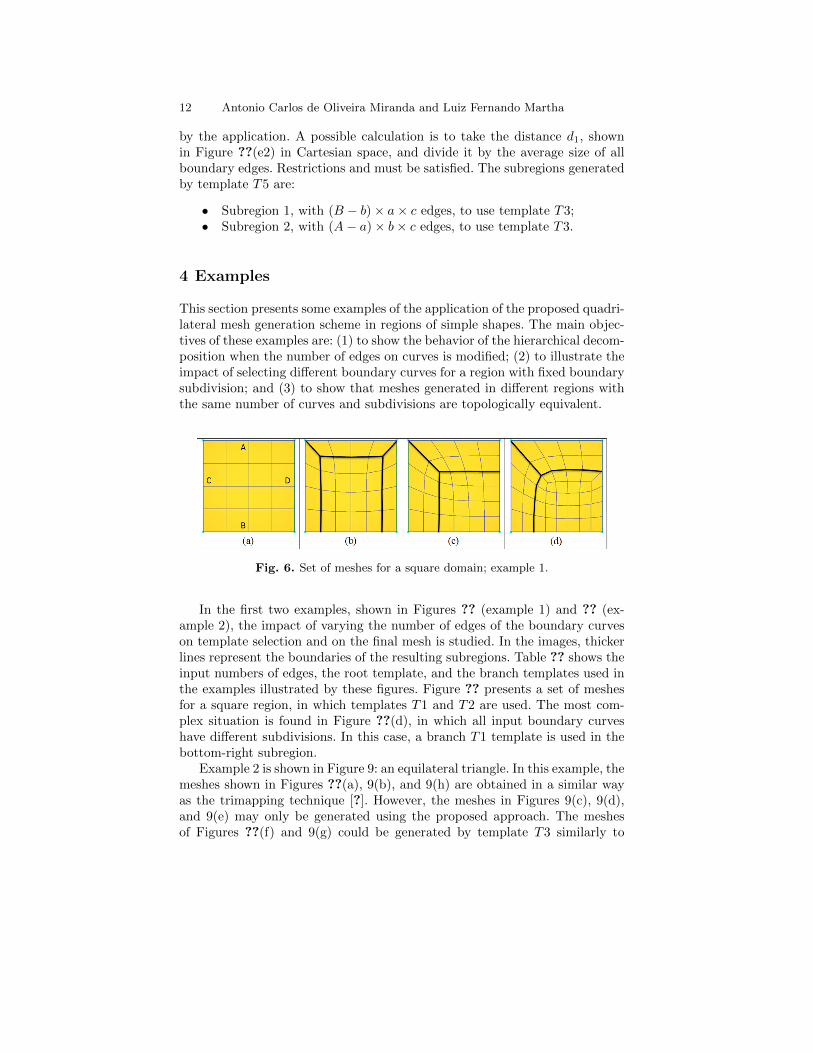
Fig. 6. Set of meshes for a square domain; example 1.
In the first two examples, shown in Figures ?? (example 1) and ?? (ex-ample 2), the impact of varying the number of edges of the boundary curveson template selection and on the final mesh is studied. In the images, thickerlines represent the boundaries of the resulting subregions. Table ?? shows theinput numbers of edges, the root template, and the branch templates used inthe examples illustrated by these figures. Figure ?? presents a set of meshesfor a square region, in which templates T1 and T2 are used. The most com-plex situation is found in Figure ??(d), in which all input boundary curveshave different subdivisions. In this case, a branch T1 template is used in thebottom-right subregion.
Example 2 is shown in Figure 9: an equilateral triangle. In this example, themeshes shown in Figures ??(a), 9(b), and 9(h) are obtained in a similar wayas the trimapping technique [?]. However, the meshes in Figures 9(c), 9(d),and 9(e) may only be generated using the proposed approach. The meshesof Figures ??(f) and 9(g) could be generated by template T3 similarly to
Quadrilateral Mesh Generation using Hierarchical Templates 13
Fig. 7. Set of meshes for an equilateral triangular domain; example 2.
Table 1. Curve refinement and templates used in examples 1 and 2.
tom region)9(g) 10 10 4 – T4 T3 (top region)9(h) 10 10 6 – T3 –
trimapping. However, template T4 is used here because it generates betterresults.
Examples 3 and 4, illustrated in Figures ?? and ??, show a set of meshesgenerated for domains with a fixed number of edges on the boundary, butwith different sets of boundary curves. The corners between boundary curvesare defined by the round marks shown in these figures, and the decompositionof the root template in subregions is represented by the thicker lines. Thenumber of curves, the root template, and the branch templates are listed inTable ??. In order to assess the quality of the generated meshes, Table ??
14 Antonio Carlos de Oliveira Miranda and Luiz Fernando Martha
Table 2. Numbers of curves and templates used in examples 3 and 4.
Figure # Curves Roottem-plate
Branch templates
10(a) 4 T2 T1 (top-right region)10(b) 3 T3 T1 (top-left region)10(c) 3 T4 T3 (top-right region) and T1 (bottom re-
gion)10(d) 3 T3 –10(e) 2 T5 T3 (top-left and bottom-right regions)10(f) 2 T5 T3 (top-left and bottom-right regions)11(a) 3 T4 T3 (top region) and T1 (bottom region)11(b) 3 T3 T1 (bottom-right region)11(c) 2 T5 2×T4⇒ 2×T3 (top and bottom regions)
and 2× T1 (middle region)11(d) 2 T5 2×T3⇒ 2×T3 (top and bottom regions)
and 2× T1 (middle-right region)
Fig. 8. Set of meshes when different boundary curves are specified for a domain,example 3.
Quadrilateral Mesh Generation using Hierarchical Templates 15
Fig. 9. Set of meshes when different boundary curves are specified for a domain;example 4.
Table 3. Mesh metrics for examples 3 and 4.
Figure # of nodes # of elements αaverage αmax αmin Standard De-viation
lists shape quality metrics for each mesh. The distortion metric used in thistable is the one proposed by Lee and Lo [?];
β =α3 × α4
α1 × α2, (7)
in which αi is adopted as the internal angle computed for each of the fourresulting triangles in the ith corner, sorted in descending order of magnitude,α1 ≥ α2 ≥ α3 ≥ α4. The shape quality metric has a valid interval between 1.0and 0.0, with high quality elements, those close to a right rectangle, havingvalues close to 1.0.
The analysis of mesh results illustrated in Figures ?? and ?? are based onthe metric values summarized in Table 3. The natural number of boundarycurves of the domain shown in Figure ?? is four. Considering this informa-
16 Antonio Carlos de Oliveira Miranda and Luiz Fernando Martha
tion, the mesh generated by the proposed procedure is shown in Figure ??(a).Alternatively, this domain can be meshed considering three curves, as shownin Figures ??(b, c, d) or two curves, as in Figures ??(e, f). Surprisingly, thebest result regarding element shape quality is a situation with three boundarycurves, as shown in Figure ??(d). A similar behavior is observed for the do-main with three curves shown in Figure ??. Although the domain has clearlythree boundary curves, the best result is obtained when two boundary curvesare considered, as in Figure ??(c). Note also that the use of template T4, Fig-ure ??(a), presents better shape quality results than the use of template T3,thereby demonstrating the need for an alternative template for three curvedomains. In both examples, the boundary is naturally defined with four orthree curves. However, better results are obtained with an alternative numberof curves. Defining the best choice of boundary curves for a given domain isoutside the scope of this work.
5 Conclusion
This work presented a hierarchical template-based quadrilateral meshingscheme. Six templates were presented: three templates with four curves, twowith three curves and one with two curves. The main concept of the proposedapproach is to decompose a region into subregions, in a recursive and hier-archical way, until achieving a subregion in which it is possible to generatequadrilateral elements using the bilinear mapping technique. Meshes of allsubregions are merged to obtain one final mesh.
Template decomposition is based on discrete bilinear and trilinear pro-jectors of parametric coordinates on boundary curves. Details of the mainprocedures were described to help readers implement them. Some of the con-tributions are:
• Two existing templates from the literature for a region with fourcurves were improved in terms of domain decomposition;
• An existing template (trimapping technique) for a region withthree curves was extended, and a restriction was removed byadding an offset correction;
• An alternative template with three curves was proposed;• A new template with two curves was proposed.
Some examples were presented, showing the behaviour of the proposedmeshing scheme when the number of edges of boundary curves is modified,and when different curves are considered as input for a region. These examplesdemonstrate how useful the proposed alternative template is for a region withthree boundary curves. In addition, they demonstrate that the original numberof curves of certain domains does not necessarily result in the best mesh whenapplying the proposed approach. Other possibilities must be tested. Finally,the proposed templates were used to create topologically equivalent source
Quadrilateral Mesh Generation using Hierarchical Templates 17
and target surface meshes in volumetric mesh generation using a sweepingtechnique.
Acknowledgements
The authors would like to thank the National Council for Scientific and Tech-nological Development (CNPq), University of Braslia, the Computer Graph-ics Technology Group (Tecgraf) and Pontifical Catholic University of Rio deJaneiro (PUC-Rio) for the financial support and for providing the necessaryspace and resources used during the development of this work.
References
1. Cook W.A. and Oakes W. R. (1982) Mapping Methods for Generation Three-Dimensional Meshes. Computer In Mechanical Engineering 67–72
2. Mitchell S.A. (2000) High Fidelity Interval Assignment. International Journalof Computatinal Geometry and Applications 10(4):399–415
3. Gordon W. J. and Hall C. A. (1973) Contruction of Curvilinear Co-ordinateSystems and Aplications to Mesh Generatio. International Journal for Numer-ical Methods in Engineering 7:461–477
4. Cook W. A. (1974) Body Oriented (natural) Co-ordinates for Generating ThreeDimensional Meshes. International Journal for Numerical Methods in Engineer-ing 8:27–43.
5. Haber R., Shephard M.S., Abel J.F., Gallagher R.H., and Greenberg D.P.(1981) A General Two-Dimensional, Graphical Finite Element PreprocessorUtilizing Discrete Transfinite Mapping. International Journal for NumericalMethods in Engineering 17:1015–1044
6. Haber R. and Abel J.F. (1982) Discrete Transfinite Mappings for Descrip-tion and Meshing of Three-Dimensional Surfaces Using Interactive ComputerGraphics. International Jornal For Numerical Methods in Enginnering 18:41–66
7. Perucchio R., Ingraffea A.R., Abel and J.F. (1982) Interative Computer Graph-ics Preprocessing for Three-Dimensional Finite Element Analysis. InternationalJournal for Numerical Methods in Engineering 18:909–926
8. Thompson J.F., Soni B.K., and Weatherill N.P. (1999) Handbook of grid gen-eration, CRC Press
9. Samet H. (1984) The Quadtree and Related Hierarchial Data Structures. ACMComputer Surveys 6(2):187–260
10. Yerry M. and Shephard M. (1983) A Modified Quadtree Approach To FiniteElement Mesh Generation. IEEE Computer Graphics and Applications 3(1):39–46
11. Baehmann P. L., Wittchen S. L., Shephard M. S., Grice K. R., and Yerry M.A.(1987) Robust, geometrically based, automatic two-dimensional mesh genera-tion. International Journal for Numerical Methods in Engineering 24(6): 1043–1078
12. Yiu K.F.C., Greaves D.M., Cruz S., Saalehi A., and Borthwick A.G.L. (1996)Quadtree grid generation: Information handling, boundary fitting and CFDapplications. Computers & Fluids 25(8):759–769
18 Antonio Carlos de Oliveira Miranda and Luiz Fernando Martha
13. Smith, R. J., and Johnston L. J. (1996) Automatic grid generation and flowsolution for complex geometries. Reston, VA, ETATS-UNIS: American Instituteof Aeronautics and Astronautics.
14. Liang X., Ebeida M.S., and Zhang Y. (2010) Guaranteed-quality all-quadrilateral mesh generation with feature preservation. Computer Methodsin Applied Mechanics and Engineering 199:2072–2083
15. Yerry M.A. and Shephard M.S. (1984) Automatic three-dimensional mesh gen-eration by the modified-octree technique. International Journal for NumericalMethods in Engineering 20(11):1965–1990
16. Zhang H. and Zhao G. (2007) Adaptive hexahedral mesh generation basedon local domain curvature and thickness using a modified grid-based method.Finite Elements in Analysis and Design, 43(9):691-704
17. Ito Y., Shih A.M., and Soni B.K. (2009) Octree-based reasonable-quality hexa-hedral mesh generation using a new set of refinement templates. InternationalJornal For Numerical Methods in Enginnering 77:1809-1833
18. Schneiders R., Schindler R., and Weiler F. (1996) Octree-based generationof hexahedral element meshes. In: Proceedings of 5th International MeshingRoundtable 1:205–215
19. Schneiders R. (2000) Algorithms for Quadrilateral and Hexahedral Mesh Gen-eration. In: Proceedings of the VKI Lecture Series on Computational FluidDynamic, VKI-LS 2000-4
20. Nowottny D. (1997) Quadrilateral Mesh Generation via Geometrically Opti-mized Domain Decomposition. In: Proceedings of 6th International MeshingRoundtable, (1):309–320
21. Mller-Hannemann M. (2000) High Quality Quadrilateral Surface MeshingWithout Template Restrictions: A New Approach Based on Network FlowTechniques. International Journal of Computational Geometry and Applica-tions, 10(3):285–307
22. Lizir M., Siqueira M., Daniels J., Silva C., and Nonato L. (2011) Template-based quadrilateral mesh generation from imaging data. The Visual Computer27(10):887–903
23. Daniels J., Lizier M., Siqueira M., Silva C.T., and Nonato L.G. (2011) Template-based quadrilateral meshing. Computers & Graphics 35(3):471–482
24. Staten M.L., Kerr R.A., Owen S.J., Blacker T.D., Stupazzini M., and ShimadaK. (2010) Unconstrained plasteringHexahedral mesh generation via advancing-front geometry decomposition. International Journal for Numerical Methods inEngineering 81(2):135–171.
25. Mitchell S.A. (1999) The All-Hex Geode-Template for Conforming a DicedTetrahedral Mesh to any Diced Hexahedral Mesh. Engineering with Computers,15:228–235
26. Yamakawa S. and Shimada K. (2001) Hexhoop: Modular Templates For Con-verting A Hex-Dominant Mesh To An All-Hex Mesh. In: Proceedings of 10thInternational Meshing Roundtable (1):.235–246
27. Ansys (2012) Documentation for Ansys - Transi-tion Mapped Quadrilateral Meshing. Available from:http://www.kxcad.net/ansys/ANSYS/ansyshelp/Hlp G MOD7 4.html.
28. Lee C. K. and Lo S. H. Lo (1994) A new scheme for the generation of a gradedquadrilateral mesh. Computers and Structures (52):847–857
29. Scott M.A., Earp M.N., and Benzley S.E. (2010) Adaptive sweeping techniques.Engineering with Computers (26):317–325
Quadrilateral Mesh Generation using Hierarchical Templates 19