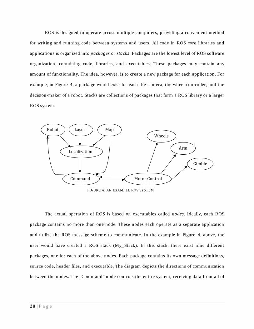
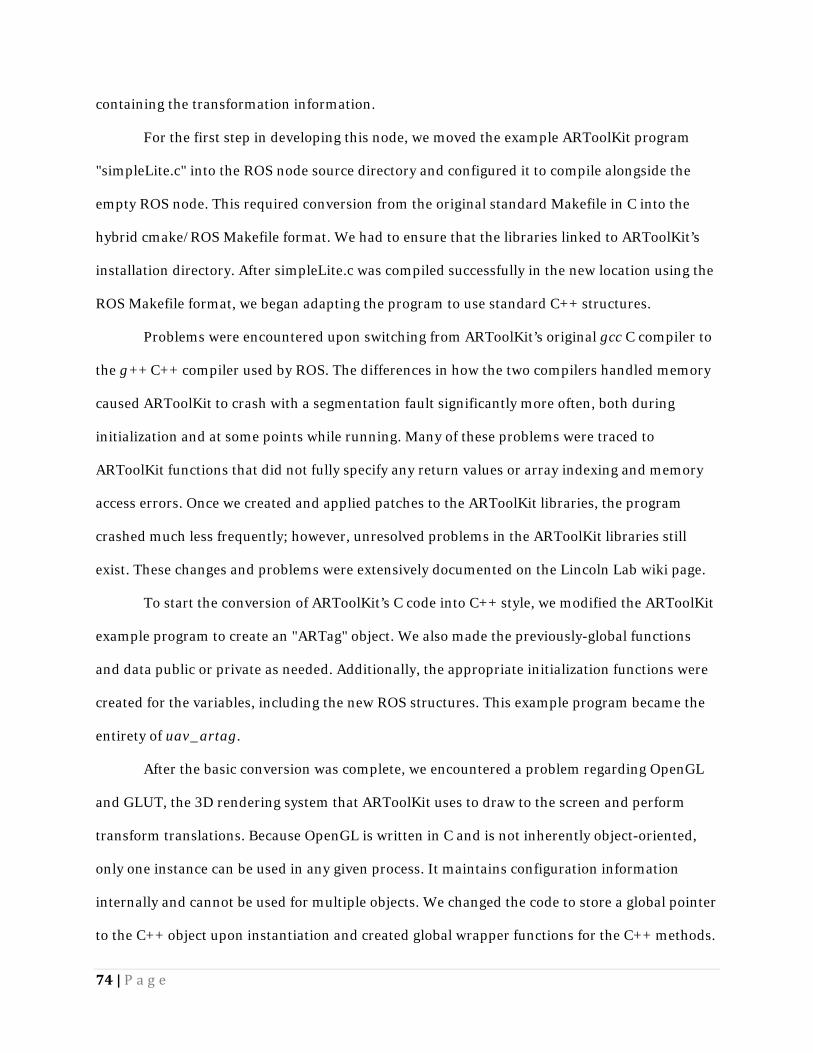
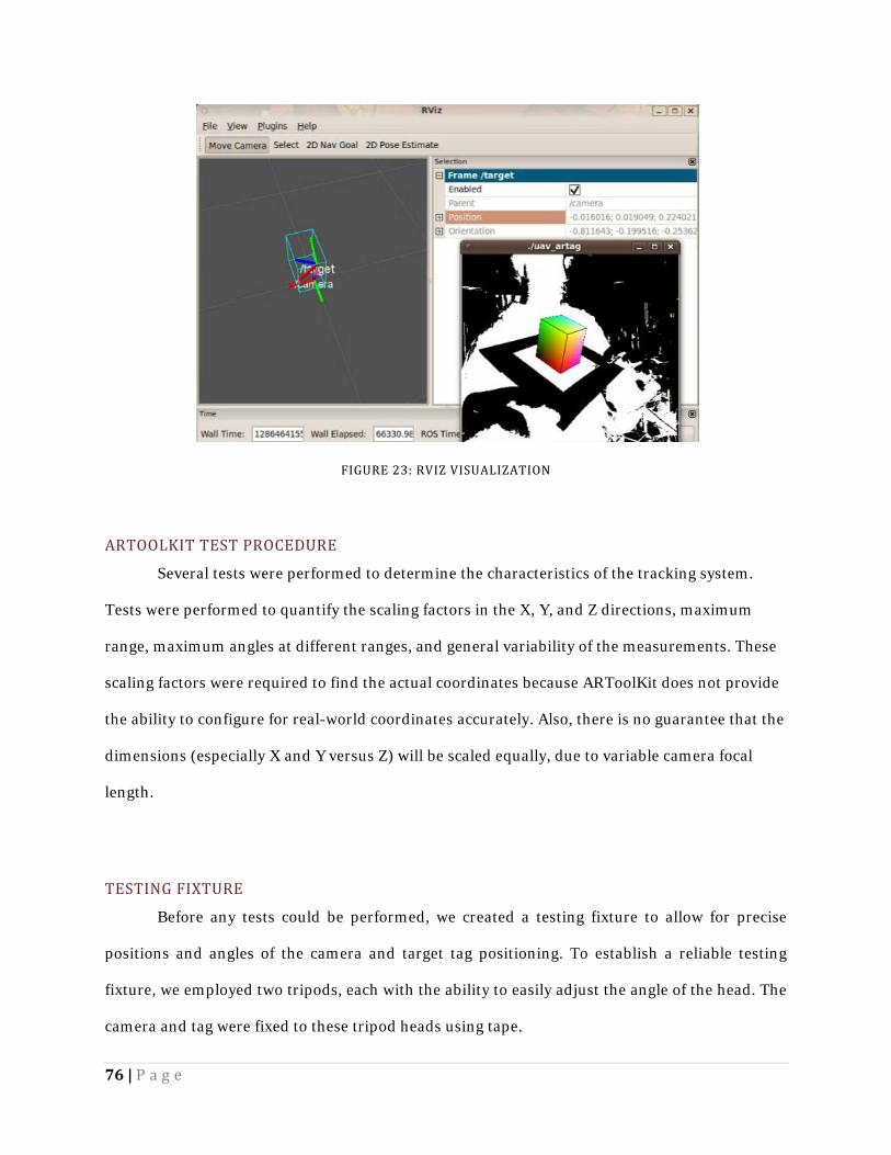
1 | Page Project Number: GTH-L101 QUADROTOR UAV INTERFACE AND LOCALIZATION DESIGN A Major Qualifying Project submitted to the Faculty of the WORCESTER POLYTECHNIC INSTITUTE in partial fulfillment of the requirements for the Degree of Bachelor of Science by _________________________ Brian Berard _________________________ Christopher Petrie _________________________ Nicholas Smith Date: October 17, 2010 Approved: ________________________________________ Professor George T. Heineman, Major Advisor ________________________________________ Professor William Michalson, Major Advisor Disclaimer: This work is sponsored by the Missile Defense Agency under Air Force Contract F19628- 00-C-0002 (1Apr00-31Mar05). Opinions, interpretations, conclusions, and recommendations are those of the authors and are not necessarily endorsed by the United States Government.
Transcript
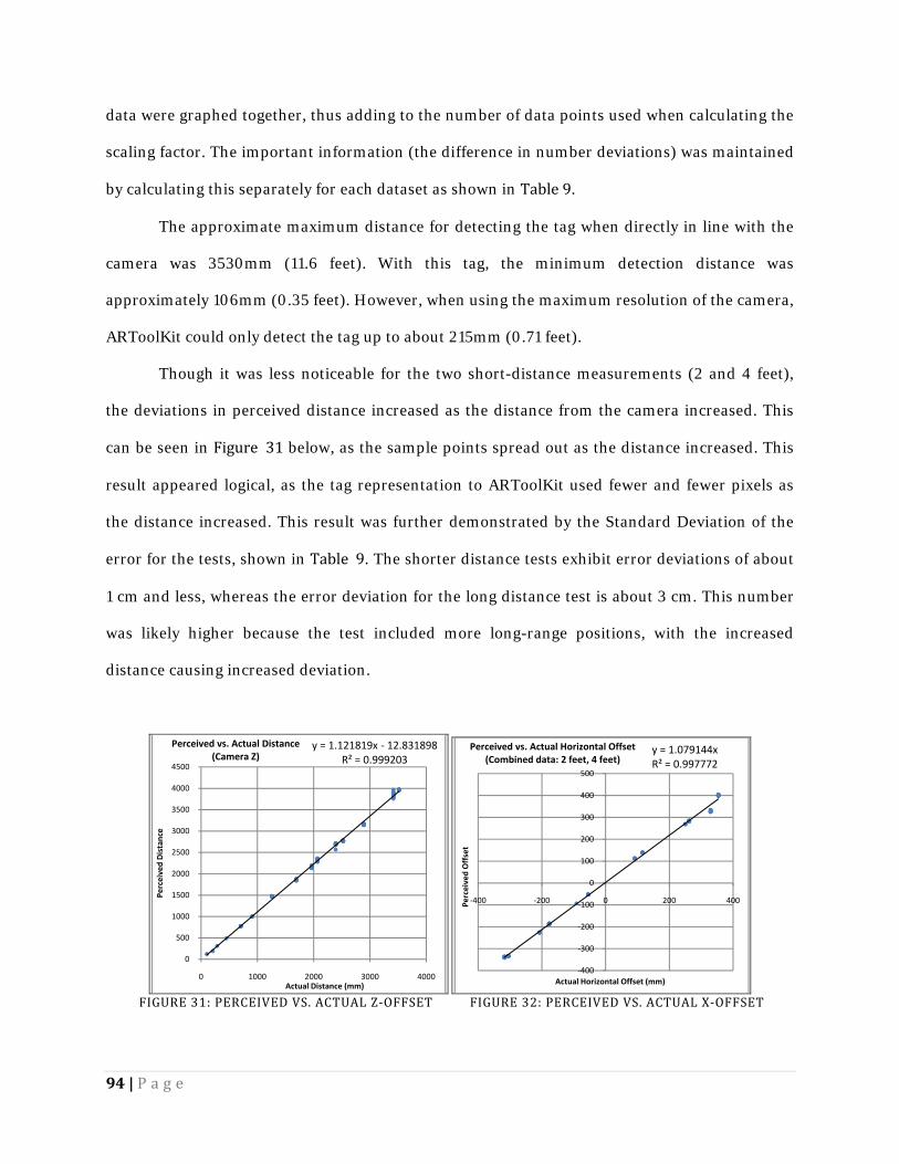
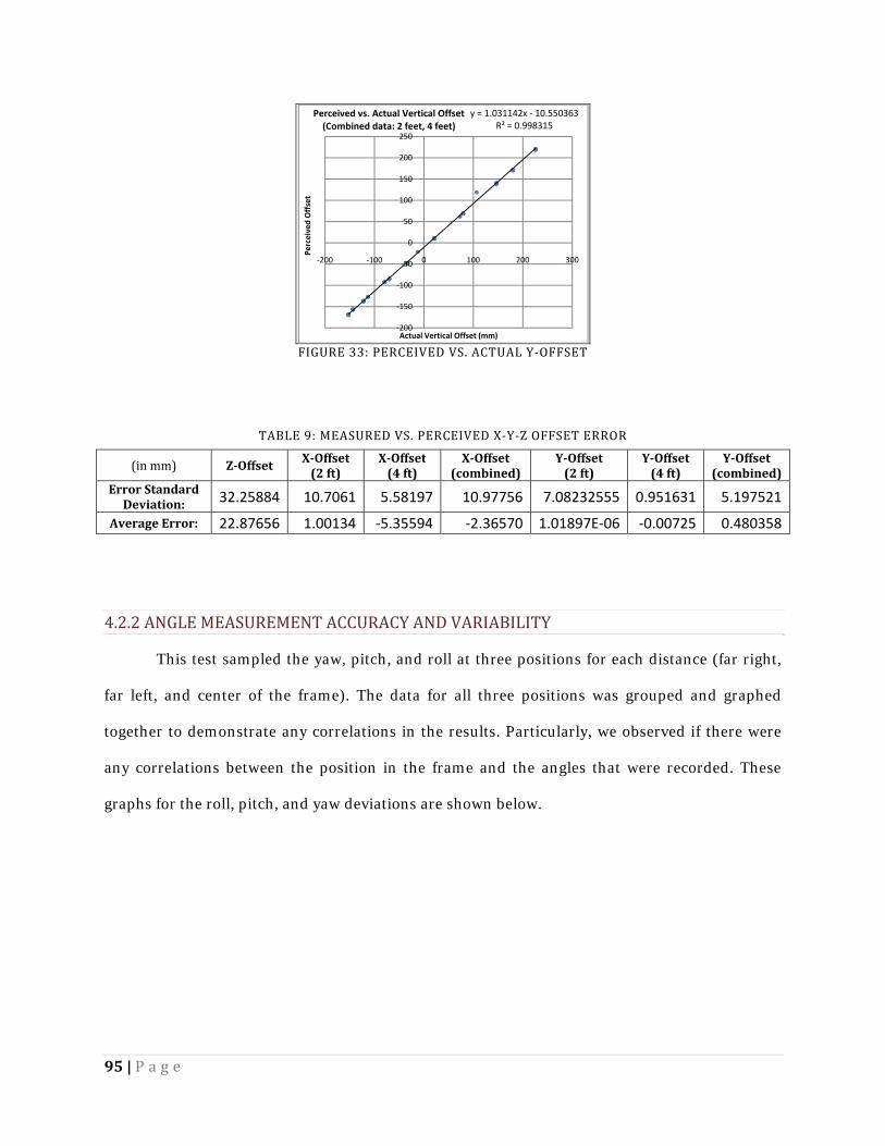
1 | P a g e
Project Number: GTH-L101
QUADROTOR UAV INTERFACE AND
LOCALIZATION DESIGN
A Major Qualifying Project
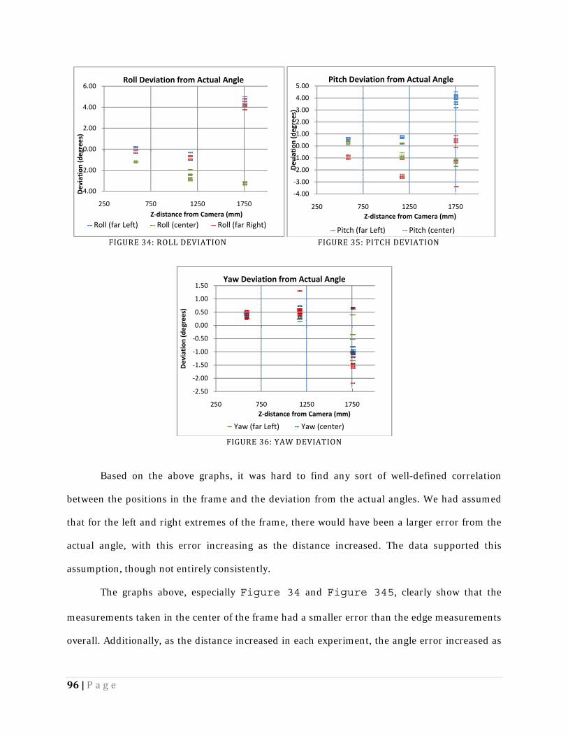
submitted to the Faculty
of the
WORCESTER POLYTECHNIC INSTITUTE
in partial fulfillment of the requirements for the
Degree of Bachelor of Science
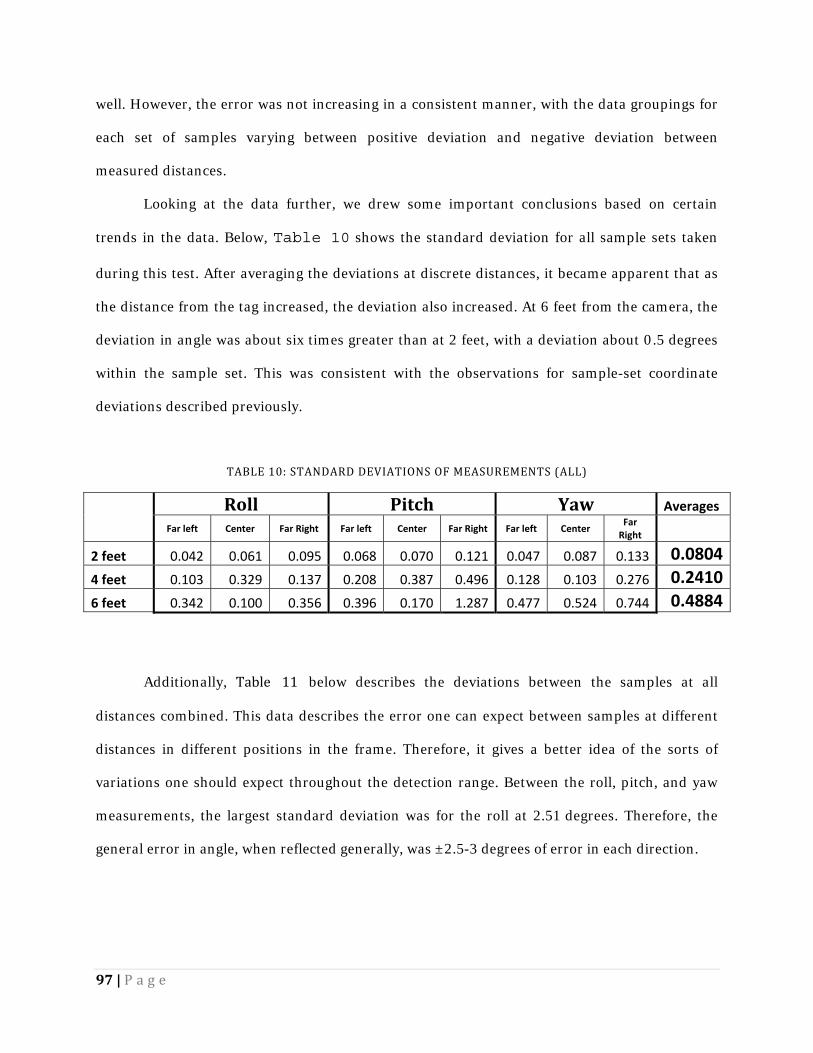
by
_________________________
Brian Berard
_________________________
Christopher Petrie
_________________________
Nicholas Smith
Date: October 17, 2010
Approved:
________________________________________
Professor George T. Heineman, Major Advisor
________________________________________
Professor William Michalson, Major Advisor
Disclaimer: This work is sponsored by the Missile Defense Agency under Air Force Contract F19628-
00-C-0002 (1Apr00-31Mar05). Opinions, interpretations, conclusions, and recommendations are
those of the authors and are not necessarily endorsed by the United States Government.
2 | P a g e
ABSTRACT MIT Lincoln Laboratory has expressed growing interest in projects involving Unmanned
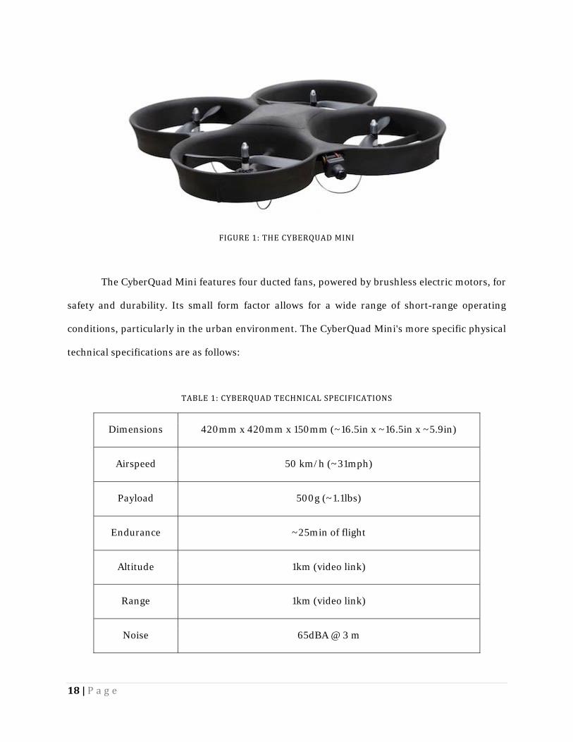
Aerial Vehicles (UAVs). Recently, they purchased a Cyber Technology CyberQuad quadrotor
UAV. Our project’s task was to assist the Laboratory in preparation for the future automation of
this system. In particular, this required the creation system allowing computerized-control of
the UAV – specifically interfacing with the software tools Lincoln Laboratory’s Group 76
intended use for future development, as well as a high-accuracy localization system to aid with
take-off and landing in anticipated mission environments.
We successfully created a computer control interface between the CyberQuad and
Willow Garage’s Robot Operating System used at the Laboratory. This interface could send
commands to and receive responses from the quadrotor. We tested the performance of the
quadrotor using our interface and compared it against the original analog control joystick.
Latency and link health tools were developed, and they indicated that our solution, while clearly
less responsive than the analog controller, would be usable after minor improvements.
To enable localization we investigated machine vision and video processing libraries,
altering the augmented reality library ARToolKit to work with ROS. We performed accuracy,
range, update rate, lighting, and tag occlusion tests on our modified code to determine its
viability in real-world conditions. Ultimately, we concluded that our current system would not
be a feasible alternative to current techniques due to inconsistencies in tag-detection, though the
high accuracy and update rate convinced us that this localization method merits future
investigation as new software packages become available.
3 | P a g e
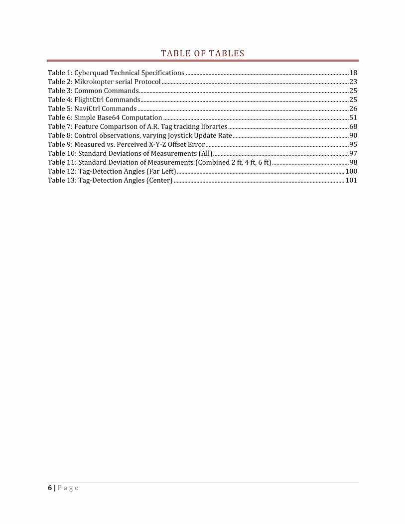
TABLE OF CONTENTS Table of Figures ........................................................................................................................................................................ 5 Table of Tables .......................................................................................................................................................................... 6 Executive Summary ................................................................................................................................................................ 7 1.0 Introduction ..................................................................................................................................................................... 11 1.1 Metrics for Success ................................................................................................................................................... 13 2.0 Background ....................................................................................................................................................................... 16 2.1 The Quadrotor ............................................................................................................................................................ 17 2.1.1 Specifications ...................................................................................................................................................... 17 2.2 Mikrokopter ................................................................................................................................................................. 20 2.2.1 MikroKopter Hardware .................................................................................................................................. 20 2.2.2 MikroKopter Software .................................................................................................................................... 23 2.3 ROS .................................................................................................................................................................................. 26 2.4 Localization: ................................................................................................................................................................ 30 2.5 Previous Projects ....................................................................................................................................................... 32 2.5.1 University of Tübingen: .................................................................................................................................. 32 2.5.2 Chemnitz University of Technology: ......................................................................................................... 33 2.5.3 J Intell Robot Systems: .................................................................................................................................... 34 2.5.4 Institute of Automatic Control Engineering: ......................................................................................... 35 2.5.5 Research Conclusion........................................................................................................................................ 36 3.0 Methodology .................................................................................................................................................................... 37 3.1 Develop PC Control Interface ............................................................................................................................... 38 3.1.1 Design Specifications ....................................................................................................................................... 40 3.1.2 Design Decisions ............................................................................................................................................... 41 3.1.3 Development ....................................................................................................................................................... 48 3.2 Enable UAV Localization ........................................................................................................................................ 65 3.2.1 Design Specifications ....................................................................................................................................... 65 3.2.2 Design Decisions ............................................................................................................................................... 67 3.2.3 Development ....................................................................................................................................................... 69 3.3 Documentation ........................................................................................................................................................... 79 4.0 Results and Analysis ..................................................................................................................................................... 81 4.1 PC Control Interface ................................................................................................................................................. 81 4.1.1 uav_health_monitor ..................................................................................................................................... 81 4.1.2 uav_teleop ............................................................................................................................................................ 89
4 | P a g e
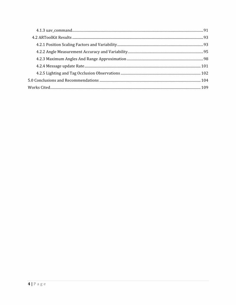
4.1.3 uav_command ..................................................................................................................................................... 91 4.2 ARToolKit Results ..................................................................................................................................................... 93 4.2.1 Position Scaling Factors and Variability .................................................................................................. 93 4.2.2 Angle Measurement Accuracy and Variability ...................................................................................... 95 4.2.3 Maximum Angles And Range Approximation ....................................................................................... 98 4.2.4 Message update Rate .................................................................................................................................... 101 4.2.5 Lighting and Tag Occlusion Observations ........................................................................................... 102 5.0 Conclusions and Recommendations ................................................................................................................... 104 Works Cited ........................................................................................................................................................................... 109
5 | P a g e
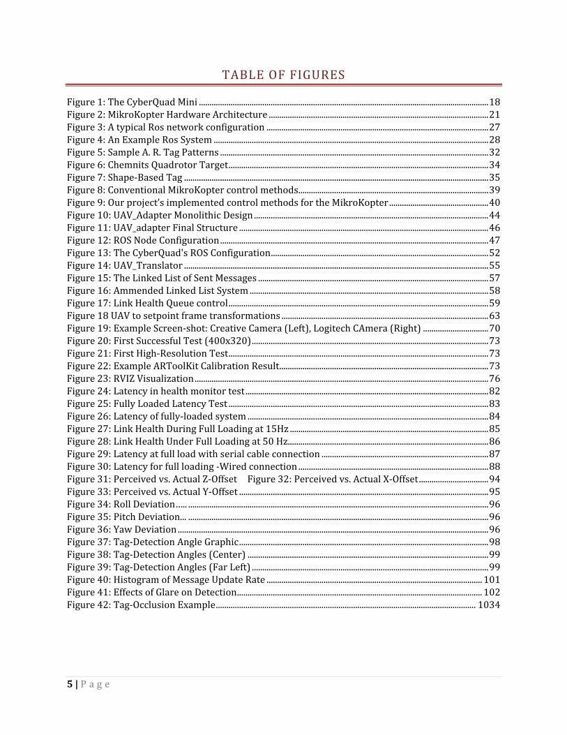
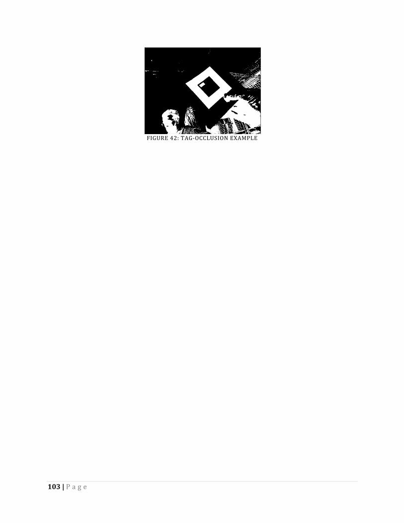
TABLE OF FIGURES Figure 1: The CyberQuad Mini ......................................................................................................................................... 18 Figure 2: MikroKopter Hardware Architecture ........................................................................................................ 21 Figure 3: A typical Ros network configuration ......................................................................................................... 27 Figure 4: An Example Ros System .................................................................................................................................. 28 Figure 5: Sample A. R. Tag Patterns ............................................................................................................................... 32 Figure 6: Chemnits Quadrotor Target ........................................................................................................................... 34 Figure 7: Shape-Based Tag ................................................................................................................................................ 35 Figure 8: Conventional MikroKopter control methods .......................................................................................... 39 Figure 9: Our project’s implemented control methods for the MikroKopter ............................................... 40 Figure 10: UAV_Adapter Monolithic Design ............................................................................................................... 44 Figure 11: UAV_adapter Final Structure ...................................................................................................................... 46 Figure 12: ROS Node Configuration ............................................................................................................................... 47 Figure 13: The CyberQuad's ROS Configuration ....................................................................................................... 52 Figure 14: UAV_Translator ................................................................................................................................................ 55 Figure 15: The Linked List of Sent Messages ............................................................................................................. 57 Figure 16: Ammended Linked List System ................................................................................................................. 58 Figure 17: Link Health Queue control ........................................................................................................................... 59 Figure 18 UAV to setpoint frame transformations .................................................................................................. 63 Figure 19: Example Screen-shot: Creative Camera (Left), Logitech CAmera (Right) ............................... 70 Figure 20: First Successful Test (400x320) ................................................................................................................ 73 Figure 21: First High-Resolution Test ........................................................................................................................... 73 Figure 22: Example ARToolKit Calibration Result ................................................................................................... 73 Figure 23: RVIZ Visualization ........................................................................................................................................... 76 Figure 24: Latency in health monitor test ................................................................................................................... 82 Figure 25: Fully Loaded Latency Test ........................................................................................................................... 83 Figure 26: Latency of fully-loaded system .................................................................................................................. 84 Figure 27: Link Health During Full Loading at 15Hz .............................................................................................. 85 Figure 28: Link Health Under Full Loading at 50 Hz............................................................................................... 86 Figure 29: Latency at full load with serial cable connection ............................................................................... 87 Figure 30: Latency for full loading -Wired connection .......................................................................................... 88 Figure 31: Perceived vs. Actual Z-Offset Figure 32: Perceived vs. Actual X-Offset ................................. 94 Figure 33: Perceived vs. Actual Y-Offset ...................................................................................................................... 95 Figure 34: Roll Deviation….. .............................................................................................................................................. 96 Figure 35: Pitch Deviation... .............................................................................................................................................. 96 Figure 36: Yaw Deviation ................................................................................................................................................... 96 Figure 37: Tag-Detection Angle Graphic ...................................................................................................................... 98 Figure 38: Tag-Detection Angles (Center) .................................................................................................................. 99 Figure 39: Tag-Detection Angles (Far Left) ................................................................................................................ 99 Figure 40: Histogram of Message Update Rate ...................................................................................................... 101 Figure 41: Effects of Glare on Detection .................................................................................................................... 102 Figure 42: Tag-Occlusion Example ........................................................................................................................... 1034
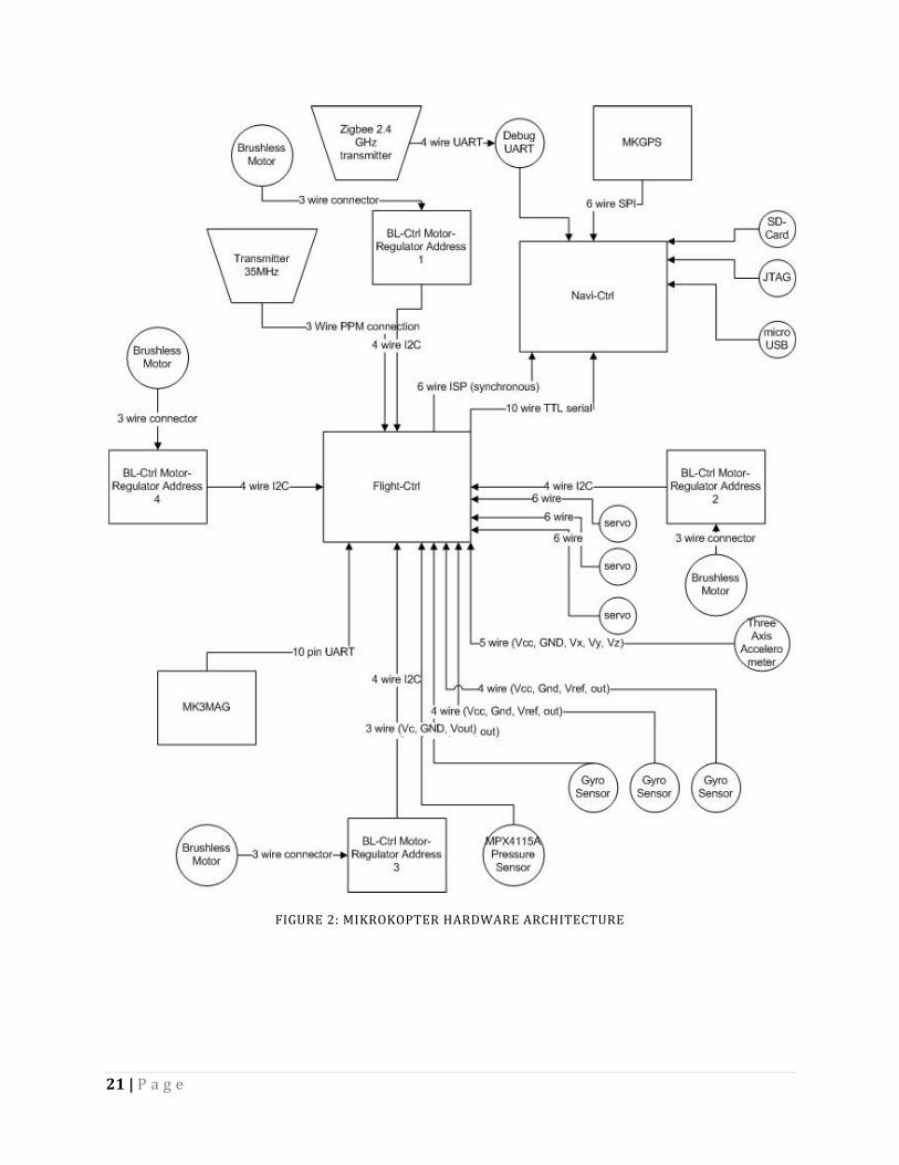
Specifically, all messages are in the following format: Start Byte (always "#"), Device
Address Byte (1 for FlightCtrl, 2 for NaviCtrl, 3 for MK3Mag), Command ID Byte (a character),
N Data Bytes (any number of bytes, including zero), and two Bytes for Cyclic Redundancy Check
(CRC), and finally the Stop Byte (always a "\r"). Each PC command may or may not produce a
resulting response from the MikroKopter software; however, if a response is sent, the Command
ID Byte character returned is the same character as was sent by the PC, but with the character
case inverted (upper case characters become the equivalent lower case letters and vice versa).
There are approximately 30 distinct serial commands that can be sent to the MikroKopter, producing about 23 different responses. A list of these commands and their responses taken directly from the MikroKopter website [6] can be found below in Table 3: Common Commands, Table 4: FlightCtrl Commands, and Table 5: NaviCtrl Commands.
Some responses are simply a "confirm frame" signifying the command was successfully received,
while others return information about the state of the MikroKopter. Specifically, the commands
are broken down into four classifications: Common, FlightCtrl, NaviCtrl, and MK3Mag
commands. Common commands return high level system information (such as the data text to
hand-held controller's display), as well as providing the means for remote movement control
(with a similar abstraction as the hand-held controller). FlightCtrl commands provide the means
for reading and writing low level system parameters, as well as a means of testing the motors.
NaviCtrl commands provide a means for sending waypoints and receiving sensor data, as well as
testing the serial port. MK3Mag command provides attitude information, though are only used
internally.
25 | P a g e
TABLE 3: COMMON COMMANDS Command Data from PC Data from MK
Analog Values u8 Channel Index u8 Index, char[16] text
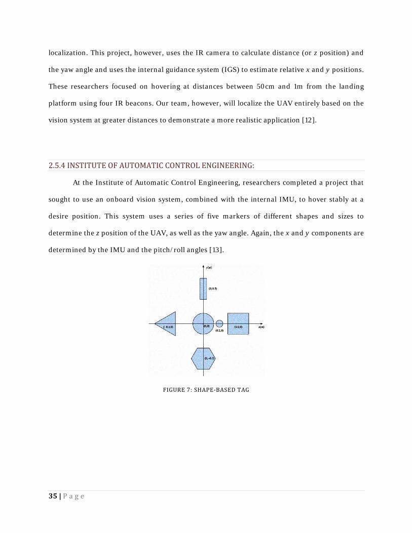
• Support for localization between the UAV and a potentially moving target
• Recognition of real-world scenarios (distance from target, light conditions, relative
velocities of objects)
37 | P a g e
3.0 METHODOLOGY Our overall goal was to provide Lincoln Laboratory with a functional UAV system upon
which they may expand in the future. To provide a strong foundation for further development,
we set three goals; the completion of which would signify a successful project. Our project
sought to: 1) create a functional PC-UAV control interface to allow commands to be sent to the
CyberQuad, with relevant sensor data being returned when requested, 2) establish a localization
scheme sufficient to operate the quadrotor with a high degree of accuracy in the 0-5ft range, and
3) provide clear documentation of our development process and the UAV’s operation for the
staff at MIT Lincoln Laboratory. Each goal represents a smaller sub-project with its own
procedures, specifications, and results. In this chapter we discuss these sections of the project
individually.
MIT Lincoln Laboratory envisioned this project as a springboard for future projects with
quadrotors and desired that we demonstrate the abilities or potential of the system. The final
product served as a proof-of-concept for quadrotor applications. We determined that the final
demonstration would include the following:
• A functional interface between ROS and the CyberQuad’s software
• Tele-operation of the CyberQuad via a ROS-controlled joystick
• A functional Augmented Reality localization system using an external camera
o Movable camera in varying positions/orientations relative to the test-bed
o Real-time, precise position/orientation knowledge feedback
o Basic position-holding control-loop using constrained quadrotor setup
GENERAL DEVELOPMENT STRATEGY To better manage this complex project and deal with the uncertainties that we foresaw in
the early stages of development, we decided to follow a parallel path, iterative design process.
38 | P a g e
Because of our short development period, we understood the potential complications that could
have arisen if we attempted to follow a linear development timeline. By dividing our project into
three separate sub-projects, one for each of our three goals mentioned above, and focusing on
specific iterations, we hoped to avoid the bottlenecks caused by a minor problem in one section
of development. As such, if a problem were to occur with the control interface development, we
would still be able to show progress in the localization scheme. Properly divided, this project
provided sufficient work to keep each member of the project busy on a completely independent
task for its duration. Each team member was charged with taking the lead role in one aspect of
the project, but also helped in other areas to provide a different perspective on difficult
problems.
3.1 DEVELOP PC CONTROL INTERFACE
SCOPE The CyberQuad system, running the open-source MikroKopter control code, was originally
intended to be operated by remote control or by pre-programmed routes programmed with a
MikroKopter control program such as QMK-Groundstation (Linux) or MikroKopter-Tool
(Windows). The first logical step in establishing a framework for future autonomous quadrotor
applications was to devise a method for the programmable control of the system. If we were
unable to use a PC to directly interface with the CyberQuad’s MikroKopter hardware, we would
not have been unable to accomplish the more sophisticated goals of the project – including
integration with ROS. Lincoln Laboratory determined that this CyberQuad system (and
MikroKopter hardware) is the platform they will be using in future, and standardizing moving to
a standard control system would facilitate accelerated collaborative development moving
forward.
39 | P a g e
We determined that the most logical method of communication to the quadrotor from
the PC was to utilize the MikroKopter hardware’s serial debugging port – the same connection
used by the stock MikroKopter control utilities, such as QMK-Groundstation. This serial link,
when connected via a wireless serial adapter, would therefore provide a simple method for
communication between the PC and quadrotor.
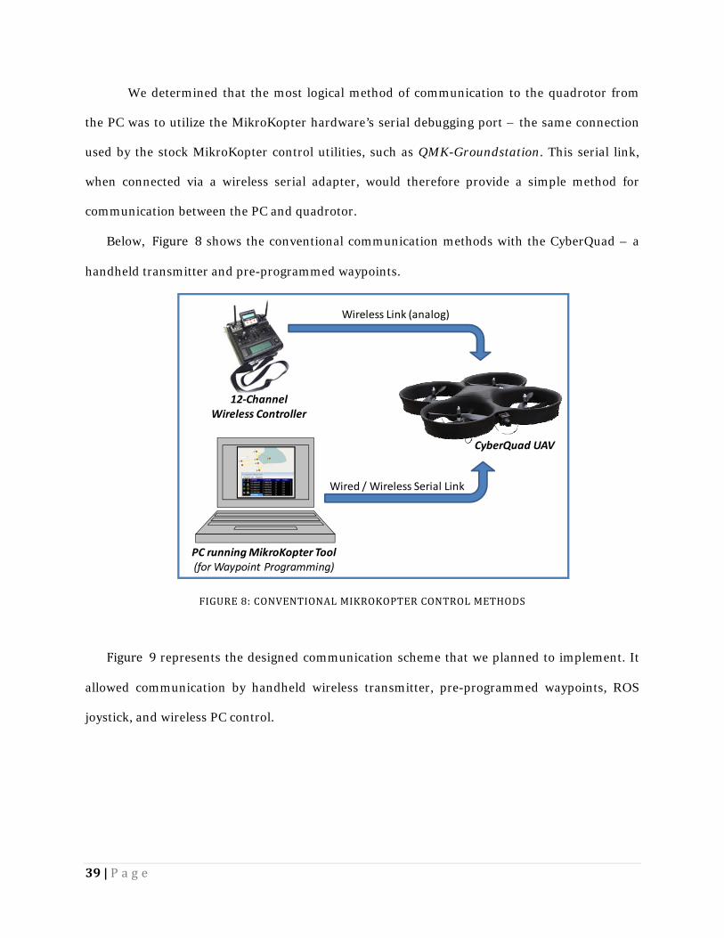
Below, Figure 8 shows the conventional communication methods with the CyberQuad – a
handheld transmitter and pre-programmed waypoints.
FIGURE 8: CONVENTIONAL MIKROKOPTER CONTROL METHODS
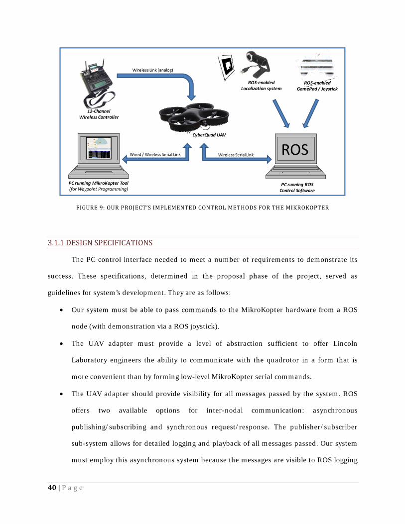
Figure 9 represents the designed communication scheme that we planned to implement. It
allowed communication by handheld wireless transmitter, pre-programmed waypoints, ROS
joystick, and wireless PC control.
PC running MikroKopter Tool(for Waypoint Programming)
12-Channel Wireless Controller
Wireless Link (analog)
Wired / Wireless Serial Link
CyberQuad UAV
40 | P a g e
FIGURE 9: OUR PROJECT’S IMPLEMENTED CONTROL METHODS FOR THE MIKROKOPTER 3.1.1 DESIGN SPECIFICATIONS The PC control interface needed to meet a number of requirements to demonstrate its
success. These specifications, determined in the proposal phase of the project, served as
guidelines for system’s development. They are as follows:
• Our system must be able to pass commands to the MikroKopter hardware from a ROS
node (with demonstration via a ROS joystick).
• The UAV adapter must provide a level of abstraction sufficient to offer Lincoln
Laboratory engineers the ability to communicate with the quadrotor in a form that is
more convenient than by forming low-level MikroKopter serial commands.
• The UAV adapter should provide visibility for all messages passed by the system. ROS
offers two available options for inter-nodal communication: asynchronous
publishing/subscribing and synchronous request/response. The publisher/subscriber
sub-system allows for detailed logging and playback of all messages passed. Our system
must employ this asynchronous system because the messages are visible to ROS logging
PC running MikroKopter Tool(for Waypoint Programming)
12-Channel Wireless Controller
Wireless Link (analog)
Wired / Wireless Serial Link
CyberQuad UAV
ROS
PC running ROS Control Software
ROS-enabled Localization system
ROS-enabled GamePad / Joystick
Wireless Serial Link
41 | P a g e
tools, while synchronous communication messages are not. This implementation will
ensure that the UAV can be operated by both high-level command nodes as well as at the
low level via the command prompt.
• Given the time constraint, our system must first implement functions for passing only
the most important messages. The adapter must be able to send basic movement-related
controls, receive navigation data, and overall ensure functional, extendible serial
communications. The serial communication test should be used to test the system for
functionality.
• The serial communication scheme must feature multi-threading to ensure simultaneous
read/write functionality.
3.1.2 DESIGN DECISIONS Before any coding began, we dedicated a significant portion of time to designing a
control system architecture that was appropriate for the task at hand. This helped to break up
the complex task of developing the quadrotor interface into more manageable components.
Furthermore, with well defined interfaces within the system, multiple individuals could work on
the same project in parallel without having to wait on the completion of one section to start
another.
INITIAL DESIGN Creating a CyberQuad control interface began with research regarding the two software
and hardware systems to be interconnected. We studied the existing MikroKopter hardware and
software of the CyberQuad, as well as ROS documentation and sample ROS systems. Our focus
was initially towards determining methods by which to exploit any existing message-passing
systems in the MikroKopter hardware and software. In particular, we intended to use the
quadrotor’s serial message protocols to provide navigation-related feedback and flight control.
42 | P a g e
In our research, we discovered that there already existed a several relevant software
projects on the topic of serial communication schemes. Within the ROS library, there were
several simple examples of serial communication nodes. Likewise, the pre-existing diagnostic
and command tool for the CyberQuad, QMK-Groundstation (the MikroKopter ground-control
center software for Linux), made use of the serial communication protocol. While neither
project fit perfectly into our program specifications, a combination of the two provided a
solution to the task of establishing PC-UAV communication.
The next step in the design of our project was to determine the level of abstraction
presented to the user of the control system. The interface concept was applied to the
CyberQuad, with the system providing an abstraction of the lower-level processes so that
Lincoln Laboratory researchers would be able to operate the UAV with simple, high-level
commands, rather than the complex low-level, ambiguous serial commands made available by
the MikroKopter software. Taking advantage of ROS’s simplified multi-process communication
system, a layered interface approach could be used in the development of the system. Once the
lowest level communication node was created, additional interface nodes could be layered on
top of this and each other, each providing a higher level of abstraction to the user than those it
builds upon. As such, the abstraction level could become increasingly higher-level as the system
undergoes development in the future.
To initiate this abstraction, we chose to first develop what we called an “adapter” - a
system providing the ROS-topic API to the to the low-level MikroKopter serial commands. This
would hide the low-level serial protocols and processes, only providing user-access to more
user-friendly commands and data. The physical data stream between the devices would only be
handled internally, as it is not immediately important to other elements in the ROS system. The
adapter we developed will allow researchers at Lincoln Laboratory to record, analyze, and repeat
the messages passed over serial communications, with the messages remaining in a human-
readable format.
43 | P a g e
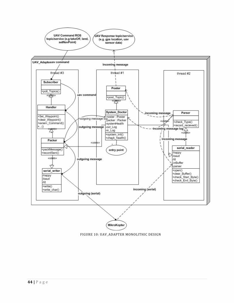
A functional adapter system required multiple processes running simultaneously to
accomplish the tasks at hand, namely: sending commands through the serial port, receiving
serial responses, and monitoring the link between the PC and the quadrotor. The two main
possibilities for the structure of the ROS-MikroKopter communication were: 1) a system
multiple ROS nodes to emulate the required “multithreading” capabilities, or 2) employ actual
C++ multithreading in a single ROS node to accomplish all of the tasks. Clearly there are
advantages and disadvantages to both methods, particularly with regard to our previous
experiences – a high degree of C++ experience, with no ROS background - and to the task at
hand. Given this, our first design developed into a single, monolithic C++ program encapsulated
within a single ROS node, as pictured in Figure 10. Moreover, this implementation would have
clearly fit the standard definition of an “interface”, in that it provides functionality to a user
through a defined API, yet hides all the implementation that provides the functionality.
Likewise, it would minimize inter-ROS node communication, as the user API could be defined to
have only a few, simple commands. Though it was against the message visibility guidelines, we
initially planned to use a request/response system for any communications that needed to
occur, as it often simplified the implementation.
44 | P a g e
FIGURE 10: UAV_ADAPTER MONOLITHIC DESIGN
45 | P a g e
FINAL DESIGN Following the initial project proposal presentation, we changed our software architecture
to more readily accommodate the desires of MIT Lincoln Laboratory. The new configuration is
shown below in Figure 11. The ROS-distributed system required message passing in the form of
visible “topics” that were visible throughout the entire ROS system. This implementation more
clearly fit our design specifications, and was therefore, the optimal choice. The primary
motivation for changing our system, however, was to enable greater low-level visibility. Our
project would be used by Lincoln Laboratory after its completion and the Laboratory engineers
required visibility access to the serial communications for the purposes of logging and repeating
experiments and procedures. This new philosophy helped to create an “adapter” that would
allow for complete and unmodified access to the MikroKopter protocols through ROS, rather
than a true system interface for the CyberQuad system. The original monolithic C++ structure
was divided up into several ROS nodes that communicate via topics (rather than request/reply
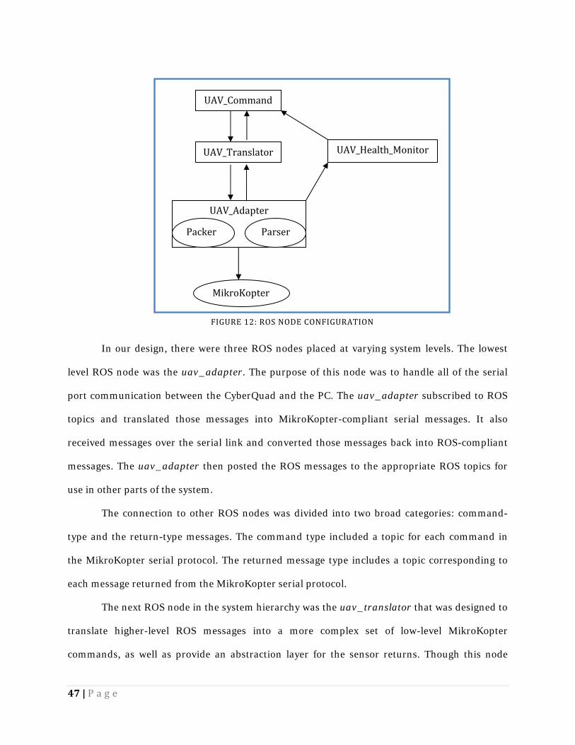
services), as seen in Figure 12.
46 | P a g e
FIGURE 11: UAV_ADAPTER FINAL STRUCTURE
47 | P a g e
In our design, there were three ROS nodes placed at varying system levels. The lowest
level ROS node was the uav_adapter. The purpose of this node was to handle all of the serial
port communication between the CyberQuad and the PC. The uav_adapter subscribed to ROS
topics and translated those messages into MikroKopter-compliant serial messages. It also
received messages over the serial link and converted those messages back into ROS-compliant
messages. The uav_adapter then posted the ROS messages to the appropriate ROS topics for
use in other parts of the system.
The connection to other ROS nodes was divided into two broad categories: command-
type and the return-type messages. The command type included a topic for each command in
the MikroKopter serial protocol. The returned message type includes a topic corresponding to
each message returned from the MikroKopter serial protocol.
The next ROS node in the system hierarchy was the uav_translator that was designed to
translate higher-level ROS messages into a more complex set of low-level MikroKopter
commands, as well as provide an abstraction layer for the sensor returns. Though this node
MikroKopter
UAV_AdapterParserPacker
UAV_Translator UAV_Health_Monitor UAV_Command
FIGURE 12: ROS NODE CONFIGURATION
48 | P a g e
would never be fully implemented for this project, it would provide the framework where future
developers could create simplified commands. In the simplified version used for this project,
this node would subscribe to a higher-level command node and pass messages to the
uav_adapter, then receive the uav_adapter’s return messages to be passed upward, acting as a
pass-through.
Finally, the highest level node was uav_command, providing the application-level
programming for the UAV control system. This node served to implement some degree of
automated control of the UAV. This way it served both as a means to test existing code and a
placeholder for future high-level development.
Another ROS node was created in parallel to this message-translation system: the
uav_health_monitor. This node subscribed to one ROS command message and one
MikroKopter returned message that existed to test the serial link. It compared the sent and
received messages and generated a metric of link health and latency, posting the results to a
separate topic.
3.1.3 DEVELOPMENT Development of the UAV adapter system involved developing a series of independent
ROS nodes, with different levels of abstraction. We were able to decompose the development
process to allow each node to be developed individually and simultaneously, and in some cases,
to enable simultaneous development of different elements of the same node. While one team
member worked on the serial communication, another was able to work on the non-serial
components of each ROS node – some of which did not even require serial communication to
fully develop. Each component was developed iteratively, often beginning with example code
from ROS or the MikroKopter QMK-Groundstation source code in early iterations. After a
sufficient understanding was achieved, the code was re-written to more accurately meet our
49 | P a g e
goals. In this section, we explain the development process for each of these major components of
the UAV adapter.
SERIAL PROTOCOL In an effort to save time in the development of the serial communication code, we
modified existing code to serve our purpose. While researching potential pre-existing ROS
nodes with serial components, we came across the ROS serial_port package. For some time, we
discussed the merits of using this seemingly functional system. Ultimately, we decided that
modifying the serial_port package as a ROS node would create too much overhead, in the form
of unnecessary ROS messages, and additional latency because every message would have to
travel through multiple sockets. Moreover, we anticipated that attempting to modify this code to
be multi-threaded would take longer than developing the multi-threaded system on our own.
Although all ROS node support multithreading through the Boost library which is included in
the core ROS library, by rewriting the serial_port package we would have had the greatest
control over the multithreaded behavior and shared serial port resources.
Although the decision was made to not use the serial_port package as a self-contained
system, we repurposed a significant amount of the C++ source code. The first issue we
encountered during the serial development portion was the inability of our operating system
(Ubuntu 2.6.13) to recognize the MikroKopter debug board (MK-USB) as a TTY device.
However, to test our code, we connected two PCs together via serial crossover cable with one PC
using our serial code to generate serial data and the other PC receiving the serial data in a
terminal window.
Eventually, we found a solution by which to accomplish serial communication across the
MKUSB. By removing the default Ubuntu package brltty, a package designed to allow for Braille
hardware interfaces, we were able to open the ttyUSB port corresponding to the MK-USB board
with both read and write capability.
50 | P a g e
Once the serial port was open, we began testing our serial code with simple MikroKopter
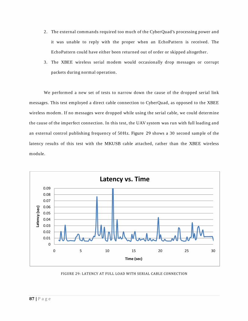
commands. During these early tests, however, communication only functioned in one direction;
we sent messages to the quadrotor, but could receive none of the expected return messages. We
employed the QMK-Groundstation software recommended by the CyberQuad developers, other
example serial code, and a direct electrical analysis of the serial port using an oscilloscope to
determine that the fault in the communication was a result of a faulty UART connector.
With a working connection, we began developing the correct MikroKopter message
frames that would allow for bi-directional communication to the quadrotor. Each MikroKopter
message was formed by a start byte, a destination address byte, message ID byte, a variable
length payload, a two byte checksum, and an end byte. We employed previous MikroKopter
communication projects in order to accelerate our development of these messages, particularly
QMK-Groundstation, the Linux equivalent to CyberQuad’s default debugging software suite.
QMK-Groundstation received feedback from the MikroKopter sensors, performed engine tests,
and configured low-level settings.
Our message generation development involved simple tests to ensure that
communication between the computer and MikroKopter was functional - sending small, well-
defined messages which provided consistent return values. We manually encoded these
messages into a buffer to be sent to the quadrotor using our serial handling code. Our
communication code successfully sent messages over the serial link to both run the engines in
test mode and to trigger system version responses. The next step in development required the
ability to send messages that carried a higher data payload, as these test messages carried very
little data.
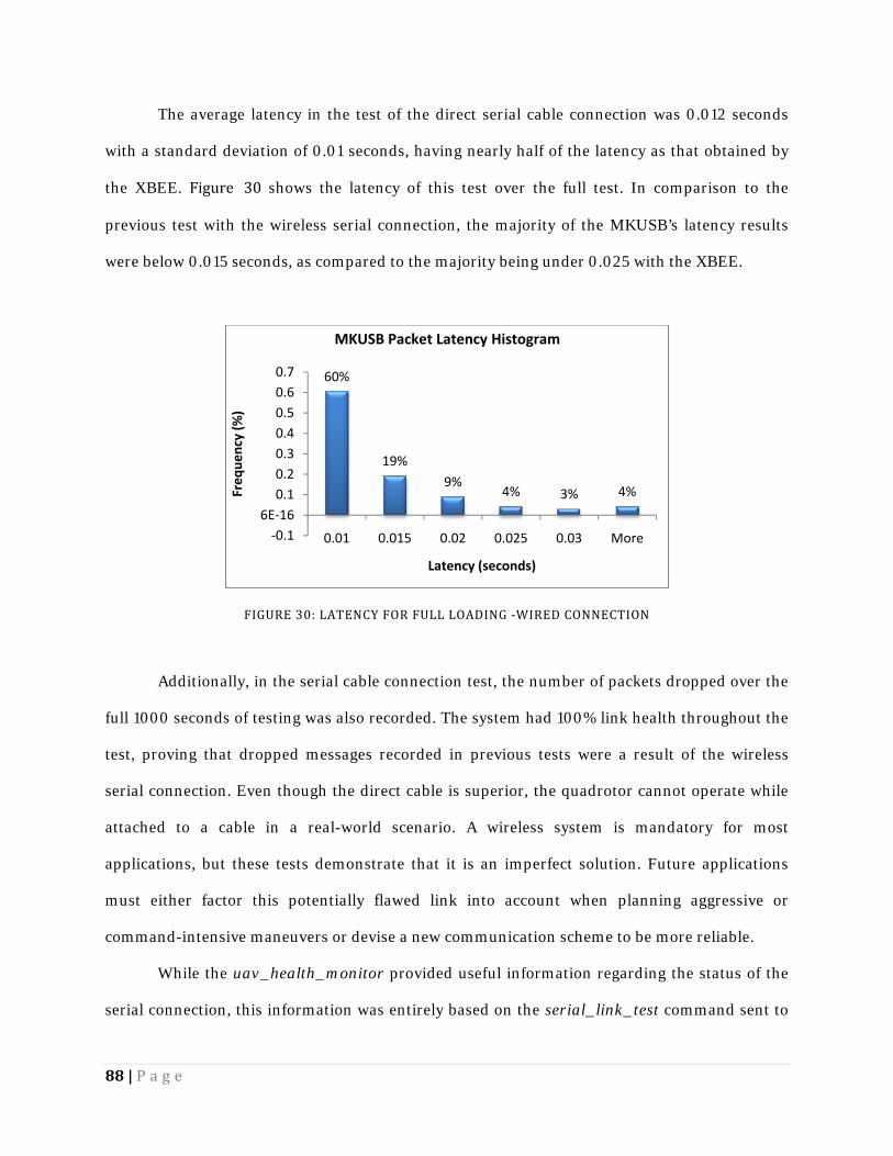
MikroKopter’s serial protocol specifies a modified 64 bit encoding scheme, which was
handled correctly by QMK-Groundstation by using the Linux Qt libraries. Our code, however,
lacked the data types and operations provided by Qt. Therefore, we had to address this encoding
ourselves to properly encode these messages. In MikroKopter’s encoding scheme, valid payload
51 | P a g e
characters range from ‘=’ (decimal 61) to ‘}’ (decimal 125). Although never explicitly explained in
the English pages of the MikroKopter Wiki, it seems that this scheme is implemented to prevent
payloads from inadvertently containing frame starting or ending characters (‘#’ decimal 35 and
‘\r’ decimal 13). Table 6 presents an example of MikroKopter’s encoding system that we
addressed in our serial code.
TABLE 6: SIMPLE BASE64 COMPUTATION Original value A (decimal) B (decimal) C (decimal) Offset value (n) a (decimal) = A + n b (decimal) = B + n c (decimal) = C + n Bit representation of new value a7a6a5a4a3a2a1a0 b7b6b5b4b3b2b1b0 c7c6c5c4c3c2c1c0
Base 64 representation 00a7a6a5a4a3a2 a1a0b7b6b5b4 00b3b2b1b0c7c6 00c5c4c3c2c1c0
We addressed, and compensated for, the encoding difficulties that arose because the data
payload was expanded in such a way that the encoded serial payload was no longer consistent
with the size specifications in the MikroKopter serial protocol documentation. For example, a
serial link test pattern was specified to have an unsigned 16 bit (2 byte) payload. When
expanded to base 64, however, the true message becomes 4 bytes - twice the anticipated data
length. Without properly accounting for this change, data payload was incomplete and
misinterpreted, and checksum generation was often incorrect; these incorrect messages were
often ignored by the MikroKopter.
ROS NODES The UAV adapter system required a number of different ROS nodes to accomplish all of
the functionality established by the design specifications. These nodes were constructed in a
hierarchical structure to fit the needs of the final system. Figure 13 shows the ROS system
52 | P a g e
configuration created for the operation of the CyberQuad. The arrows demonstrate the
directions of communication between the nodes. The uav_msgs node does not communicate
with any of the other nodes, but it supplies message definitions to all of them. Additionally,
Joystick_Ctrl was not created specifically for the quadrotor; it is a commonly-used ROS node
that was adapted to operate with this particular hardware and project.
uav_adapter
The uav_adapter involved three different classes to perform the multithreading
functions of serial I/O for which this node was designed. The first class, the Packer, subscribed
to messages from a node higher in the hierarchy of the UAV adapter system, converted the
messages to a MikroKopter-compatible format, and sent those messages over serial to the
quadrotor. The second class in the uav_adapter was the Parser. This class received returned
serial messages from MikroKopter, parsed those messages back into a ROS-readable format,
and published them back into the ROS system. The final class was the UAV_Adapter class that
* This node contributes to every ROS node, but doesn’t directly communicate with any.FIGURE 13: THE CYBERQUAD'S ROS CONFIGURATION
53 | P a g e
provided the constructors and destructors for the Packer and the Parser. Each of these classes
was developed individually due to their independent functionality. This division of the
uav_adapter into separate objects allowed all the group members to work effectively in parallel.
The first step in developing the uav_adapter was to establish the base class,
UAV_Adapter to handle the constructors and destructors of each thread. In the early stages of
development, we created placeholders for the constructors of the Parser and Packer to ensure
that each thread was instantiated correctly. Initial development of multithreading began with
the creation of a method in the UAV_Adapter class that called separate methods to instantiate
the Packer and Parser as separate threads using the boost::thread method. To confirm that the
multithreading was working properly, the constructors in the Parser and Packer were
temporarily configured to continuously print status messages. Be viewing the output of the
UAV_Adapter class’s execution, we were able to confirm that several threads were executing
simultaneously and functioning correctly.
Once the serial communication code had been implemented, revisions were made to the
Parser and Packer constructors to allow for references to shared resources to be passed into the
object to allow for simultaneous use of the serial port. Additionally, a boost::mutex object was
created in the UAV_Adapter class, to which both the Packer and Parser were provided access.
By locking and unlocking this mutex around critical sections in the executed code, the shared
serial resource was protected. The Packer served to write to the serial connection, while the
Parser performed all read functions simultaneously.
In the Parser, we developed a state machine that received a series of data characters
from the incoming serial buffer and reconstructed them into a full message. Based on the known
start and end bytes of the MikroKopter serial protocol and the checksum analysis code from the
QMK-Groundstation, we determined the difference between correct and corrupted messages.
The Parser would then publish these reconstructed ROS messages to a node higher in the UAV
system hierarchy.
54 | P a g e
For the message reconstruction code, we created a set of structures for the relevant
MikroKopter messages to be copied into. This way, we had access to specific fields of a message
by first casting that message into a general structure. Once the data fields of a received
MikroKopter message were all processed, the information was inserted into a ROS message
structure and posted to the appropriate ROS topic.
The Packer was constructed in a similar manner. In its idle state, it continuously polled
the topics to which it subscribed for new messages from other nodes in the hierarchy. When it
received a message, it triggered a callback function that created a message with the required
MikroKopter message ID and populated the outgoing message with the proper data fields. Then
the message was sent over the serial link to the MikroKopter.
To ensure that the entirety of the system was functioning as a whole, we had a separate
ROS node, the uav_health_monitor, send out MikroKopter echo packets. These messages were
interpreted by the Packer, triggered in the correct callback, packed into the correct data frame,
and sent over the serial to the MikroKopter hardware. The MikroKopter generated a response
message and returned it over the serial link. The Parser then reconstructed the message byte-
by-byte, and forwarded the correct message back into the UAV system. The
uav_health_monitor listened for this return message, and determined if messages had made it
around the full loop to the MikroKopter and back.
uav_translator
The uav_translator node was originally designed to act as an abstraction layer
converting higher level commands to low-lower level (such as those used by uav_adapter). For
this project, it served a slightly different purpose, simply re-routing messages from other nodes
to the uav_adapter. Additionally, this node received return data from the MikroKopter after it
has been read from serial, parsed, and sent as a MikroKopter-returned ROS message from the
uav_adapter. This node was also designed to receive these return messages, translate them into
55 | P a g e
a more usable, higher-level message, and post them to topics readable by nodes higher in the
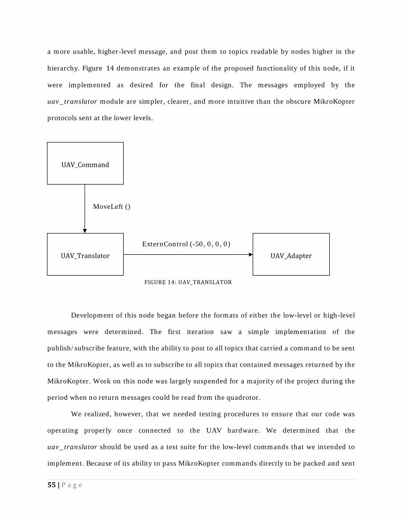
hierarchy. Figure 14 demonstrates an example of the proposed functionality of this node, if it
were implemented as desired for the final design. The messages employed by the
uav_translator module are simpler, clearer, and more intuitive than the obscure MikroKopter
protocols sent at the lower levels.
Development of this node began before the formats of either the low-level or high-level
messages were determined. The first iteration saw a simple implementation of the
publish/subscribe feature, with the ability to post to all topics that carried a command to be sent
to the MikroKopter, as well as to subscribe to all topics that contained messages returned by the
MikroKopter. Work on this node was largely suspended for a majority of the project during the
period when no return messages could be read from the quadrotor.
We realized, however, that we needed testing procedures to ensure that our code was
operating properly once connected to the UAV hardware. We determined that the
uav_translator should be used as a test suite for the low-level commands that we intended to
implement. Because of its ability to pass MikroKopter commands directly to be packed and sent
FIGURE 14: UAV_TRANSLATOR
UAV_Command
UAV_Translator UAV_Adapter MoveLeft ()
ExternControl (-50, 0, 0, 0)
56 | P a g e
over serial, this node worked well for testing. It published test messages and subscribed to the
responses. This node contained none of the multithreading complications inherent in directly
testing the uav_adapter, and it allowed for easy comparison between commands sent and
responses received.
Finally, framework for adding high-level commands in the future was established.
Several example messages were implemented in code, albeit not fully, though the framework has
been established for use by future developers. In future iterations of this particular node, the
number of topics the uav_translator publishes and subscribes to must be increased. At the
completion of this project, the translator only published those messages that we found to be
most relevant to providing the proof-of-concept system. Many of the minor functions of the
MikroKopter serial protocol remained unimplemented in each translating, sending, and
receiving.
uav_health_monitor
The uav_health_monitor was an addition to our adapter system to provide an indication
about the state of the messages being passed to and from the CyberQuad system. In the first
iteration of this node, it subscribed to all of the important message topics, both from the
uav_translator and the uav_adapter. The uav_health_monitor implemented a linked list to
store a queue of message times on the “sent” side of the uav_adapter. It would then assign
message times coming from the “received” side of the quadrotor to a separate queue. Over a
specified time period, the uav_health_monitor would build these queues, and at the end of that
period, it would calculate the average latency over that time period, compare the number of
messages sent to the number of messages received to determine link health, advance the queues,
and clear old messages.
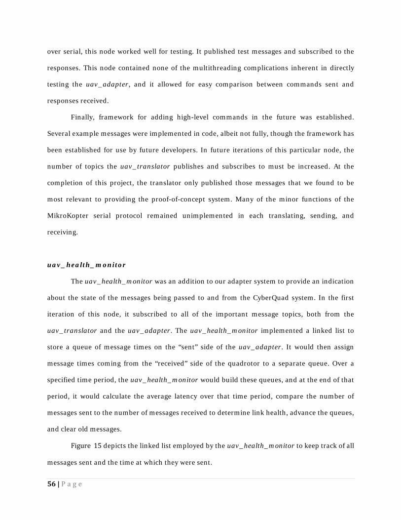
Figure 15 depicts the linked list employed by the uav_health_monitor to keep track of all
messages sent and the time at which they were sent.
57 | P a g e
Soon after development began, we realized an problem in our design. With the
uav_health_monitor subscribing to so many messages, if a message were dropped, there was no
way of knowing what message it was. Additionally, the queues of messages only stored a
timestamp, and no other relevant data. Finally, this method provided only a sampling of link
health; it would potentially fall very behind in the queues while it processed the data, advanced,
and cleared the queues. We determined also that this implementation would take a significant
amount of time to develop and test. This would likely require modifying the MikroKopter
firmware to provide timestamps as a field on all return messages, for a full implementation.
After re-evaluating the uav_health_monitor, we developed an entirely different
technique f or monitoring link health. This time, we used the built-in MikroKopter serial
command serial_link_test to monitor the connection. The uav_health_monitor sent a message
to the MikroKopter at a user-defined rate that carried an “EchoPattern,” (an unsigned integer)
and the quadrotor would return that same value. The queue was changed to store only the
serial_link_test messages sent from the uav_health_monitor – their EchoPattern, or index#,
and a timestamp. This message would be read by the uav_adapter, sent to the MikroKopter,
and the response received. When the uav_adapter posted the return message, a callback
function in the uav_health_monitor assigned the incoming message a “return time”. It would
then compare the index of the incoming message to the first message in the queue of sent
messages. A mismatch implied a dropped message, and could be handled accordingly.
Otherwise, the uav_health_monitor calculated latency based on the sent time vs. return time, as
well as the link health based on the number of packets dropped over a certain time interval.
FIGURE 15: THE LINKED LIST OF SENT MESSAGES
Serial Link Test Message Time A *Ptr to Next Msg Serial Link Test Message Time B *Ptr to Next Msg Serial Link Test Message Time C *Ptr to Next Msg
58 | P a g e
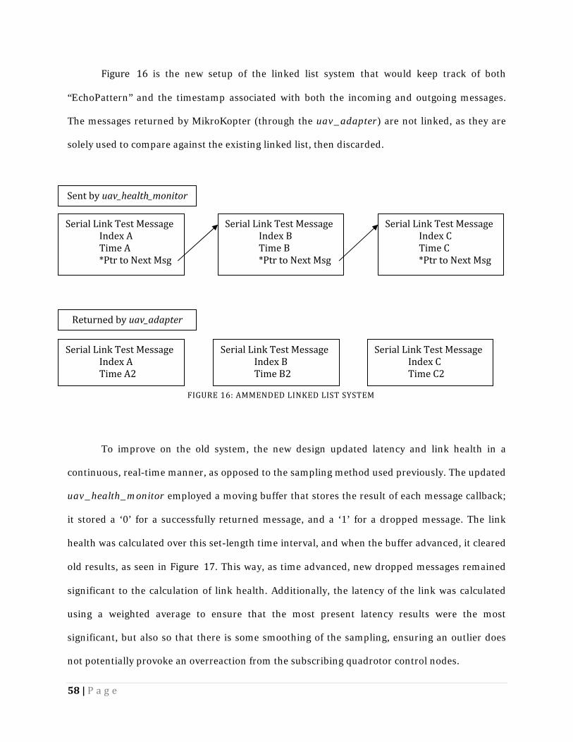
Figure 16 is the new setup of the linked list system that would keep track of both
“EchoPattern” and the timestamp associated with both the incoming and outgoing messages.
The messages returned by MikroKopter (through the uav_adapter) are not linked, as they are
solely used to compare against the existing linked list, then discarded.
To improve on the old system, the new design updated latency and link health in a
continuous, real-time manner, as opposed to the sampling method used previously. The updated
uav_health_monitor employed a moving buffer that stores the result of each message callback;
it stored a ‘0’ for a successfully returned message, and a ‘1’ for a dropped message. The link
health was calculated over this set-length time interval, and when the buffer advanced, it cleared
old results, as seen in Figure 17. This way, as time advanced, new dropped messages remained
significant to the calculation of link health. Additionally, the latency of the link was calculated
using a weighted average to ensure that the most present latency results were the most
significant, but also so that there is some smoothing of the sampling, ensuring an outlier does
not potentially provoke an overreaction from the subscribing quadrotor control nodes.
Serial Link Test Message Index A Time A *Ptr to Next Msg Serial Link Test Message Index B Time B *Ptr to Next Msg
Serial Link Test Message Index C Time C *Ptr to Next Msg Sent by uav_health_monitor
Returned by uav_adapter
Serial Link Test Message Index A Time A2 Serial Link Test Message Index B Time B2 Serial Link Test Message Index C Time C2 FIGURE 16: AMMENDED LINKED LIST SYSTEM
59 | P a g e
In a late evaluation of this node’s functionality, however, we noticed another
shortcoming in its design. While the uav_health_monitor kept track of the number of dropped
messages, latency, and link health, this information was only made available to other nodes
when that information could be calculated (if and only if a response was received from the
MikroKopter). If, for some reason, the link was disconnected, the user wouldn’t necessarily be
aware of the dropped connection because uav_health_monitor only publishes a message after
receiving that response. Thus, we implemented a timing system to monitor the responses and
ensure that a response is received every few seconds (the exact value to be assigned by the user).
Otherwise, uav_health_monitor publishes to a separate topic that alerts any subscribers that
the link is disconnected. Upon re-establishing connection, the node returns to normal operation.
This node was completed with all of the specified functionality. Additional functionality
could be added to monitor another MikroKopter command, rather than having an entire
publisher-subscriber topic just for testing the link health. In a more advanced quadrotor system,
this extra serial_link_test topic might place unnecessary burden on the serial port that could be
avoided by sampling the output of another message. The best possible alternative would be to
FIGURE 17: LINK HEALTH QUEUE CONTROL
Callback from uav_adapter
0 1 0 0 0 0 0 0 1 0 0
1
Original Queue
0 1 0 0 0 0 0 0 1 0 0Delete Buffer
60 | P a g e
monitor the external command (which has a confirm frame similar to the serial test message) or
the OSD data (navigational data returned from the MikroKopter at user-defined intervals)
comparing return time to the expected return time as defined by one of the MikroKopter serial
commands. For the purposes of our project and projects in the near future, however, this
implementation was determined to be more than sufficient.
uav_teleop
This simple node serves to allow for ROS joystick (in this case, a dual 2-axis Logitech
Gamepad) control of the quadrotor for the main purpose of testing. Many ROS-enabled robots
at Lincoln Laboratory utilize this controller, and we felt it appropriate to adopt the same
standard. Building off of ROS’s built-in joystick control functionality, uav_teleop subscribes to
the joystick node’s output messages (in the form of two arrays: axis[] with one element for each
joystick axis, and buttons[] with one element for each button on the controller). This node then
converts these values into quadrotor-specific functionality for each axis and button.
Our joypad implementation features handling for two analog control sticks (altitude and
yaw, pitch and roll) and four buttons. The first button enables the ‘locking’ of output thrust,
meaning that you can set the UAV to a desired thrust using the control stick, hold this button
and release the control stick and the UAV will continue to receive the same thrust. The second
button acts as a scaling mechanism for the joystick axis in the event that the operator wishes to
issue more precise commands to the quadrotor. For example, without the scaling, full left on the
left control stick might make the quadrotor rotate at a rate of 1 radian/second. With the scaling
button pressed, it would only rotate at a maximum rate of 0.5rad/sec. This function allows the
user to adjust the control scheme in real-time for more precise maneuvers. The third button
allowed for the re-centering of the thrust control stick. From our limited flight experience, we
concluded that it was useful to have the default position of the thrust control stick to be the
value that makes the quadrotor hover. However, because this value can vary substantially from
61 | P a g e
flight to flight, it could not be hardcoded into the software or even passed as a parameter on the
launching of the ROS node. Instead we had this button take the current value of the thrust and
adjust all subsequent values so that the new default value of the control stick was hover. The
final button was simply a reset button, which reset the centered control stick back to its original
configuration.
The uav_teleop node existed as a framework for future implementation. Though we did
implement the essential control elements, we did not experiment with all of the MikroKopter’s
serial commands to determine if there were others that were valuable to implement on the
controller. Future projects will likely find a number of additional uses for the buttons on the
gamepad, and this node is designed to easily support adding new functionality.
uav_command
We developed uav_command as the central processing center for the quadrotor’s
operation. This node would operate above the uav_translator and uav_adapter in the
hierarchy and pass high-level commands through the uav_translator. All sensory systems – AR
vision, GPS data, sensor fusion, etc. – would be analyzed and combined in this node to
determine the UAV’s best course of action.
Due to time constraints, however, we were unable to fully implement all of the
functionality for which this node was designed. Instead we created a framework for anticipated
future applications. Additionally, we also programmed a number of test cases into the current
version of the uav_command to demonstrate proof-of-concept and provide an outline for future
developers.
One of the primary means by which to quantitatively measure the functionality of the
UAV system as a whole was to write and retrieve data from a log file for analysis. We used the
standard C++ I/O libraries and some file manipulation to output the results of the various
62 | P a g e
processes of the UAV system to comma separated value (*.csv) files for later analysis. Persistent
data could now be saved outside of ROS for more extensive external analysis.
Additionally, in order to test our localization system, we created the means by which to
specify an arbitrary 3D coordinate anywhere in space in respect to the augmented reality test tag
and then calculate the difference between this “setpoint” and actual position of the UAV based
on the localization data provided by uav_artag. To accomplish this error calculation, we made
use of ROS’s built-in frame transformation messages. Every time uav_artag detected an
augmented reality tag, it would post the orientation and position data as a frame
transformation. The uav_command subscribed to these messages, and would combine the
incoming data with frame transformation information about the UAV’s position in respect to the
camera, upon receiving a message. This allowed for the construction of a ROS frame
transformation tree and for the forwards kinematics calculation of the setpoint (initially set in
respect to the coordinate frame of the augmented reality tag) transforming it into the coordinate
frame of the UAV. This vector was then parsed into the component X, Y, and Z error (the specific
measurement of meters between the desired and actual position of the UAV). Figure 18 shows
the transformation process and the relationship between the tag’s frame of reference, the UAV’s
frame of reference, and the test setpoint that we defined.
63 | P a g e
FIGURE 18 UAV TO SETPOINT FRAME TRANSFORMATIONS Finally, in an effort to showcase the functionality of both our localization and
MikroKopter control interface simultaneously, we implemented a very simple position-hold
control loop. We used our previously-mentioned transformation code to calculate the error
between actual UAV position and desired position, and passed these error values into a PI
(proportional, integral) feedback control loop. Error in the X and Z-coordinates of the UAV were
handled by setting the roll and pitch, respectively, of the UAV. For example, if the target setpoint
were in front of the UAV (a negative Z value) and to the right (a positive X value), the
transformation system would send a positive value to the UAV’s external control pitch field and
a negative value to its roll field, causing it to pitch forwards and roll right. The overall thrust
provided to the system was a function of absolute magnitude of the error – the greater the error,
the larger a “gas” value generate. If the Y-error specified the UAV was above the target location,
64 | P a g e
the gas was reduced from the amount of thrust required to hover, allowing the quadrotor to
descend. If the Y-error indicated the UAV was below the target point, gas was added to the hover
thrust to raise the UAV.
A number of situations were not addressed in our simple framework implementation of
the control loop. One of the issues occurred when uav_artag momentarily lost sight of the tag.
We implemented a solution to this problem in which the UAV would revert to the “hover” thrust
and zero yaw, pitch, roll orientation when no tags were visible. Another issue left un-addressed
was that of yaw control of the quadrotor. The system clearly is capable of moving in any
direction horizontal to the ground plane without changing yaw (y-axis in the UAV frame), but
for our limited testing purposes no yaw control was implemented. However, it is worth noting
that in a real-world implementation, control over yaw would be necessary in order to keep the
augmented reality tag in the viewing angle of the camera at all times.
uav_msgs
Unlike the other nodes in the UAV system, this node contains no actual C++ code or
executables. The uav_msgs node provides the message definitions used in the UAV structure.
Without this node, the other packages would have to contain dependencies on one another,
which could potentially have caused circular dependencies if two nodes were required to
communicate. Now, all quadrotor packages only depend on one standardized package to provide
all of the necessary messages.
In future projects, this package will see a large amount of improvement. Any new UAV
node will contribute msg files to uav_msgs. One such example is the uav_command node that
had to add new high-level messages that were not implemented during our project.
65 | P a g e
3.2 ENABLE UAV LOCALIZATION SCOPE A number of potential real-world quadrotor applications require relative localization
between a UAV and ground-based system. For example, the execution of a safe, reliable landing
on the back of a potentially moving unmanned ground vehicle (UGV) requires the knowledge of
the UAV’s position relative to the ground vehicle in real-time with a high degree of precision.
The GPS systems built into each vehicle provide an excellent method of tracking one another at
long ranges. However, the resolution of the GPS modules possesses a level of error in shorter
ranges that is compounded in relative position calculations.
The UAV's vision system can be employed to facilitate a more precise localization. We
decided to use the vision data to control the quadrotor’s relative position to the ground platform.
Accurate knowledge of its location allows a UAV to accomplish a number of tasks including, but
not limited to, landing. Any vision system that we developed could also be employed in a
number of different future projects.
3.2.1 DESIGN SPECIFICATIONS This project included two well-defined components; the UAV adapter (the integration of
MikroKopter hardware with ROS), and system localization (the modification and encapsulation
of vision processing libraries in ROS). The constraints and specifications developed in the initial
phases of the project for developing this localization scheme were separated into those relating
to the UAV, those relating to the ground-station testing computer containing the ROS server,
and those relating to the implementation and performance of the localization system. This
section presents those specifications developed in the initial planning phase of the project.
66 | P a g e
UAV SPECIFICATIONS The method chosen for localization must easily integrate with the CyberQuad UAV
platform. As such, any additional hardware required must be light enough to fit the maximum
payload (500 grams) and weight distribution constraints specified for our device. Additionally, it
must be able to either interface with the MikroKopter hardware boards and firmware, or operate
completely independently, sending information directly to the ground station. In either case, the
system could not interfere with the normal flight operations of the system.
If a camera (visual) system was used, these constraints are thus made more specific.
Specifically, if a camera other than the model in the current CyberQuad package was necessary,
the new system would have to integrate with the existing transmitter and camera angle-control
system, or would have to be an entirely separate system.
GROUND STATION SPECIFICATIONS While the ground station does not have weight and size requirements as specific as the
UAV, there are several considerations to be made if the ground station is to remain mobile. First
of all, any device used cannot exceed the dimensions of the platform. Additionally, the method
for localization should not interfere with the operation of the ground station or the flight of the
UAV. As such, the system should include minimal protrusions which might be hazardous to
UAV flight operations. Any hardware that the ground station employs must be compatible with a
Linux-based PC with standard hardware. However, in terms of this project, the main hardware
limitation is that the localization device must be securely attached to the ground station.
Because the ground station must run Linux with ROS, the software developed for the
localization method must be compatible with the provided interfaces. Specifically, all programs
must be written in a language which can send and receive messages using the ROS constructs
(currently limiting us to either Python or C++). Also, these programs must operate in real-time,
and provide low-latency, accurate, and precise information about the current state of the
67 | P a g e
system. These systems must also account for connection problems, gracefully handling error
conditions without damaging hardware.
LOCALIZATION SPECIFICATIONS With a vision based system, the cameras and capture systems would need to provide a
detailed view of the environment. They must provide a wide field of view, providing for a large
coverage area of the ground platform, as well as providing a high-quality image. For the system
to function in real world environments, the images must be returned with extremely low latency
and must automatically adjust for environmental changes in lighting through adjustments in the
brightness and contrast levels of the output image.
Assuming the Augmented Reality Tag system is used, the libraries used, and software
developed, must be able to distinguish the specified tag from the noise of the environment.
From this, the software must be able to provide position coordinates and orientation
information relative to the camera's view of the tag. The software must also be able to handle
views of the tag at extreme angles. Finally, it must compensate for problems with sporadic target
loss.
In general, the solution for localization should provide a level of accuracy higher that
what can be obtained using traditional methods, including GPS or IGS. This includes superior
close-range localization, various environment support, and superior update rates.
3.2.2 DESIGN DECISIONS INITIAL DESIGN
To properly determine its three-dimensional location and orientation with respect to a
landing platform, the initial UAV design used an entirely camera-based system that tracked a
specially-designed target. The image processing would run in a single ROS node, which would
68 | P a g e
then post the UAV’s position/orientation information to a standard ROS transform construct to
be read by the general UAV controller node. This controller was intended to serve as the
governing controller for all future UAV applications. It was designed to receive all relevant UAV
sensor data and make critical decisions based on this input. FINAL DESIGN Several augmented reality tag libraries were considered for this project: ARTag,
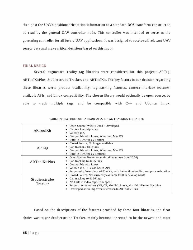
ARToolKitPlus, Studierstrube Tracker, and ARToolKit. The key factors in our decision regarding
these libraries were: product availability, tag-tracking features, camera-interface features,
available APIs, and Linux compatibility. The chosen library would optimally be open source, be
able to track multiple tags, and be compatible with C++ and Ubuntu Linux.
TABLE 7: FEATURE COMPARISON OF A. R. TAG TRACKING LIBRARIES
ARToolKit • Open Source, Widely Used / Developed • Can track multiple tags • Written in C • Compatible with Linux, Windows, Mac OS • Built-in 3D Overlay Feature
ARTag • Closed Source, No longer available
• Can track multiple tags • Compatible with Linux, Windows, Mac OS • Built-in 3D Overlay Features
ARToolKitPlus • Open Source, No longer maintained (since June 2006) • Can track up to 4096 tags • Compatible with Linux • Written in C++, class-based API • Supposedly faster than ARToolKit, with better thresholding and pose estimation
Studierstrube Tracker
• Closed Source, Not currently available (still in development) • Can track up to 4096 tags • No built-in video capture support • Support for Windows (XP, CE, Mobile), Linux, Mac OS, iPhone, Symbian • Developed as an improved successor to ARToolKitPlus
Based on the descriptions of the features provided by these four libraries, the clear
choice was to use Studierstrube Tracker, mainly because it seemed to be the newest and most
69 | P a g e
actively-maintained project with the most features and support. As a successor to
ARToolKitPlus, it claimed to include all the same functionality, but with improved performance.
It provided the most features, the best tracking ability (based on the sample videos), and the
most diverse platform compatibility. However, we were unable to procure a license to use this
product.
Then, the next obvious choice would be ARToolKitPlus, since it was available,
compatible with our system, provided a C++ class-based API, and was described as an
improvement over ARToolKit. However, it did not provide an integrated solution for capturing
frames from a video source like ARToolKit did. In addition, it did not provide a built-in feature
for 3D overlays that provided useful testing information. Lastly, according to the change-logs,
the last active development of ARToolKit was more recent than ARToolKitPlus.
Despite the improvements ARToolKitPlus describes, the decision was made to develop
with ARToolKit. This library seemed to have more active projects than the other alternatives. By
using a widely-used library, we assumed that there would be more development information and
documentation available. Also, ARToolKit was still officially an active development project.
ARTag was not considered because it has not been in development for several years and the
source files are no longer available. 3.2.3 DEVELOPMENT REQUIRED HARDWARE For testing purposes in parallel to quadrotor development without employing the actual
quadrotor hardware, we researched and procured several webcams for ARToolKit testing using
the most widely-supported hardware available. In future projects, these webcams could also
eventually be used as additional tag-tracking cameras on the ground-station. Additionally, we
obtained several video capture interfaces to allow the tag-tracking software to make use of the
70 | P a g e
video from the CyberQuad sent over the wireless receiver. These webcams represent only an
"optimal-case" video source because the CyberQuad would need a better standard camera
available to accomplish these same results.
After our research, we obtained two webcams that we thought would be most optimal for
this application: a Logitech QuickCam Pro 9000, and a Creative Live! Optia AF webcam. These
two webcams were chosen because they provided a high-resolution, high-frame rate video
output, auto-focus (allowing for close and far range tag tracking), and Linux compatibility.
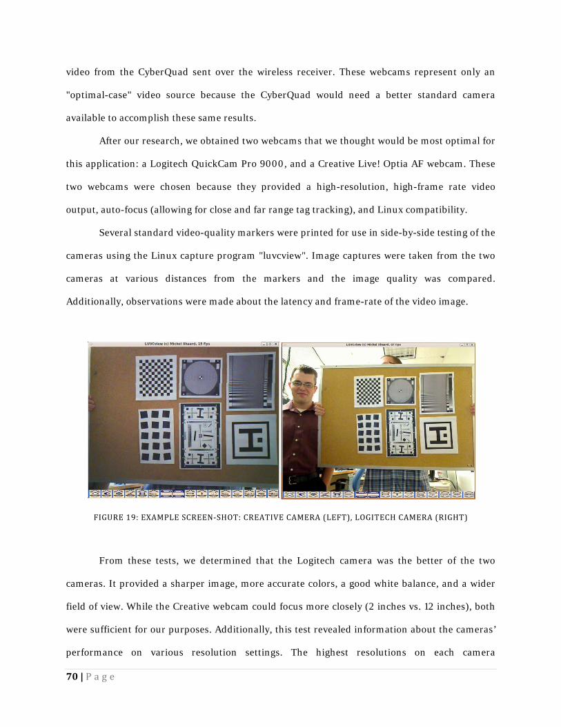
Several standard video-quality markers were printed for use in side-by-side testing of the
cameras using the Linux capture program "luvcview". Image captures were taken from the two
cameras at various distances from the markers and the image quality was compared.
Additionally, observations were made about the latency and frame-rate of the video image.
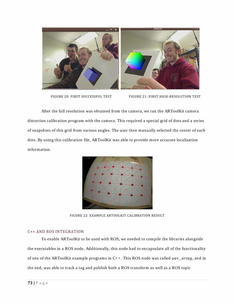
FIGURE 19: EXAMPLE SCREEN-SHOT: CREATIVE CAMERA (LEFT), LOGITECH CAMERA (RIGHT)
From these tests, we determined that the Logitech camera was the better of the two
cameras. It provided a sharper image, more accurate colors, a good white balance, and a wider
field of view. While the Creative webcam could focus more closely (2 inches vs. 12 inches), both
were sufficient for our purposes. Additionally, this test revealed information about the cameras’
performance on various resolution settings. The highest resolutions on each camera
71 | P a g e
(1600x1200) only allowed for 15fps video, versus 30fps with the standard 640x480 resolution.
The higher resolution video seemed to have about 0.25 second of latency, whereas the standard
resolution produced a higher latency of about 1 second.
To capture the video transmitted from the UAV, a 5.8 GHz “Nano 5.8” wireless receiver
was obtained from Iftron Technologies, as well as a 4-port composite PCI video interface by
Hauppauge and a USB “Video Live 2” interface by Hauppauge. A significant amount of time was
spent trying to obtain and install the proper drivers for these devices so the actual video camera
from the UAV could be used in testing. However, we were unable to configure the capture cards
with the systems available and we decided to continue testing using only the webcams. ARTOOLKIT INSTALLATION & CONFIGURATION The ARToolKit Augmented Reality Tag tracking suite was designed to overlay OpenGL
objects over tags shown in a video feed. ARToolKit provides functions that will return the
position and orientation of the tag in a 3x4 matrix, both with respect to the tag and to the
camera using a built-in transform function. Additionally, this software provides a means to
calibrate for camera distortion and depth of field.
This program requires the Video4Linux and GStreamer packages be installed on the
system. Video4Linux provides an abstraction of a video source (such as a webcam), and
GStreamer provides a pipeline interface for manipulating video streams in Linux. According to
the documentation, Video4Linux can be used alone, or in conjunction with GStreamer to
connect the video input with ARToolKit.
While it may work "out of the box" on older systems, the example program binaries in
the "bin" folder with default parameters did not immediately work on our system. These
example programs were designed to perform simple tests, such as opening the video display and
overlaying a 3-Dimensional box over an example tag in the frame. ARToolKit was originally
compiled for use with Video4Linux or with a joint Video4Linux-GStreamer system, but in the
72 | P a g e
end, we were only able to get it to work with the joint Video4Linux-Gstreamer option.
Initially, we attempted to make the ARToolKit example files work with only Video4Linux
because it is installed by default in Ubuntu. However, when we attempted to run any of the
example binaries, the programs would immediately crash upon trying to open the video device.
We assumed the problem was a result of the default parameters used to configure the camera,
we modified these parameter settings. After numerous failed attempts, we chose to use
GStreamer to bridge the connection between ARToolKit and the Video4Linux abstraction.
Getting GStreamer to route the video to ARToolKit in the correct format was also very
difficult. Using the GStreamer utility called "gst-launch-0.10", we were able to test different
pipelines and export the end result to a window on the screen. We eventually discovered a
pipeline that showed the image from the webcam on the screen to verify that GStreamer could
indeed read from the webcam through the Video4Linux source.
Next, we entered this pipeline into the ARToolKit example projects as the stream
parameters. This, however, did not work and program crashed on launch for resolutions greater
than 400x320. With this pipeline, the example program "simpleTest" opened properly and
could track the example tag (the center tag from Figure 5: Sample A. R. Tag
Patterns). This was sufficient for some preliminary testing, but the system required
improvement to support the full resolution of the camera. By changing some undocumented
parameters that set the Video4Linux width and height before resizing by the GStreamer
pipeline, we were able to open the video source at the full resolution and track the tag.
73 | P a g e
After the full resolution was obtained from the camera, we ran the ARToolKit camera
distortion calibration program with the camera. This required a special grid of dots and a series
of snapshots of this grid from various angles. The user then manually selected the center of each
dots. By using this calibration file, ARToolKit was able to provide more accurate localization
information.
FIGURE 22: EXAMPLE ARTOOLKIT CALIBRATION RESULT C++ AND ROS INTEGRATION To enable ARToolKit to be used with ROS, we needed to compile the libraries alongside
the executables in a ROS node. Additionally, this node had to encapsulate all of the functionality
of one of the ARToolKit example programs in C++. This ROS node was called uav_artag, and in
the end, was able to track a tag and publish both a ROS transform as well as a ROS topic
FIGURE 21: FIRST HIGH-RESOLUTION TEST FIGURE 20: FIRST SUCCESSFUL TEST
74 | P a g e
containing the transformation information.
For the first step in developing this node, we moved the example ARToolKit program
"simpleLite.c" into the ROS node source directory and configured it to compile alongside the
empty ROS node. This required conversion from the original standard Makefile in C into the
hybrid cmake/ROS Makefile format. We had to ensure that the libraries linked to ARToolKit’s
installation directory. After simpleLite.c was compiled successfully in the new location using the
ROS Makefile format, we began adapting the program to use standard C++ structures.
Problems were encountered upon switching from ARToolKit’s original gcc C compiler to
the g++ C++ compiler used by ROS. The differences in how the two compilers handled memory
caused ARToolKit to crash with a segmentation fault significantly more often, both during
initialization and at some points while running. Many of these problems were traced to
ARToolKit functions that did not fully specify any return values or array indexing and memory
access errors. Once we created and applied patches to the ARToolKit libraries, the program
crashed much less frequently; however, unresolved problems in the ARToolKit libraries still
exist. These changes and problems were extensively documented on the Lincoln Lab wiki page.
To start the conversion of ARToolKit’s C code into C++ style, we modified the ARToolKit
example program to create an "ARTag" object. We also made the previously-global functions
and data public or private as needed. Additionally, the appropriate initialization functions were
created for the variables, including the new ROS structures. This example program became the
entirety of uav_artag.
After the basic conversion was complete, we encountered a problem regarding OpenGL
and GLUT, the 3D rendering system that ARToolKit uses to draw to the screen and perform
transform translations. Because OpenGL is written in C and is not inherently object-oriented,
only one instance can be used in any given process. It maintains configuration information
internally and cannot be used for multiple objects. We changed the code to store a global pointer
to the C++ object upon instantiation and created global wrapper functions for the C++ methods.
75 | P a g e
To allow multiple ROS ARToolKit nodes to exist and communicate, we used standard
ROS parameters from the Parameter Server as a method of configuring the GStreamer, tag, and
camera settings. These parameters could be set in a ROS Launch File, or, if left unspecified, set
to the defaults defined in the C++ class.
The next step in the development of the localization scheme was to address the
conversion between ARToolKit output data and ROS transforms. The transformation matrix
returned by ARToolKit, containing the rotation and orientation of the tag, was returned as a 3x4
transformation matrix. ROS transforms, however, use a different format, known as
“Quaternion”, to store the rotation information. Thus, the transformation matrix was separated
into the location and rotation elements, and these elements were used with ROS conversion
functions to create the standard ROS transform objects. These transforms are different than
standard topics and are always available to every node. However, because a transform is not
included in a ROS bag file, we converted this transform into a standard ROS topic containing the
same information. These transform messages were verified using the ROS built-in transform
visualization application, rviz. Figure 23 shows an example of ARToolKit transforms being
converted into ROS transforms and their visualization in rviz.
76 | P a g e
FIGURE 23: RVIZ VISUALIZATION
ARTOOLKIT TEST PROCEDURE Several tests were performed to determine the characteristics of the tracking system.
Tests were performed to quantify the scaling factors in the X, Y, and Z directions, maximum
range, maximum angles at different ranges, and general variability of the measurements. These
scaling factors were required to find the actual coordinates because ARToolKit does not provide
the ability to configure for real-world coordinates accurately. Also, there is no guarantee that the
dimensions (especially X and Y versus Z) will be scaled equally, due to variable camera focal
length.
TESTING FIXTURE Before any tests could be performed, we created a testing fixture to allow for precise
positions and angles of the camera and target tag positioning. To establish a reliable testing
fixture, we employed two tripods, each with the ability to easily adjust the angle of the head. The
camera and tag were fixed to these tripod heads using tape.
77 | P a g e
The camera was calibrated by using the target tag on the tripod. First, uav_artag was
modified to print out the X, Y, and Z perceived coordinates and a timestamp every time a
message was sent for the duration of these tests. The end result of “calibrating the camera” on
the tripod was such that the act of moving the target away from the camera along a straight line
on the floor did not cause the perceived X and Y position values to change. Assuming the tag
originally started at the X-Y origin (center), the lack of X-Y variation means that the camera is
perfectly level with the floor. We ran uav_artag and adjusted the parameters on both tripods
until the tag was as near the X-Y origin as possible.
POSITION SCALING FACTORS AND VARIABILITY To determine the scaling factors in each dimension, we performed a series of tests that
compared the perceived values from ARToolKit with the physically measured values. During this
testing phase, we tested each dimension individually while the two other dimensions were held
as constant as possible. Additionally, the tag orientation remained as fixed as possible and
always faced in a plane parallel to the camera. After moving the target tripod, the new distance
offset was measured using a measuring tape, and then uav_artag was started, printing
coordinates to the screen. For each offset, samples were reported to the screen and one second
worth of data was randomly selected, using the corresponding timestamps.
Specifically for the Z-direction measurements, the X and Y coordinates were held as
constant as possible, with the target tag held as close to the center of the frame as possible while
the target moved away from the camera until it was no longer detected. For the X-direction test,
the Y and Z coordinates remained fixed while the target tripod was moved left and right. A
similar test was performed for the Y-direction in with the X and Z coordinates were fixed and
the target tripod moved up and down. However, because it was unknown if there was a
relationship between the Z value and the X or Y value, the same tests were performed again for
the X and Y dimensions, using different Z distances.
78 | P a g e
By assuming that the other two dimensions were fixed during measurement, we could
plot the perceived offsets versus the actual measured offsets to determine the linear relationship
between the two and convert the ARToolKit units into actual units. Additionally, by collecting
one second’s worth of samples, we received information about the sample rate, as well as the
ability to derive the approximate measurement error using the model. ANGLE MEASUREMENT ACCURACY AND VARIABILITY
Our next test helped us to obtain a general sense of the accuracy and variability of the
angles being measured by ARToolKit. During this test, the target tag, set at the same height as
the camera, was moved to various distances away from the camera, and ten samples were taken
from ROS of the roll, pitch, and yaw angles. For each distance, samples were taken on the left
and right extremes of the frame, as well as in the center. We assumed that the vertical axis
showed similar results if the tag was instead moved up and down. We determined the accuracy
and variability of ARToolKit using actual measured angles of the tag and these samples taken
from ROS.
MAXIMUM ANGLES AND RANGE APPROXIMATION Our next test was to gain a general understanding of the maximum range of the
ARToolKit system. The question of range depended on the camera resolution, the tag size, the
position in the frame, the lighting conditions, and the maximum required recognition angle. As
such, the test was performed to provide an approximate answer for the specific setup utilized
during this testing phase.
During this test, the target tripod, at the same height as the camera, was moved to
different distances away from the camera along the far left edge of the image frame. Next, at
each distance, we varied the yaw of the tag by rotating the tag clockwise until the tag was no
79 | P a g e
longer consistently or accurately detected. Similarly, at each distance, the yaw of the tag was
rotated in the counter-clockwise direction. This first test would determine the worst case angle
for that distance, and the second determined the best case.
This measurement was performed several times, moving back until the maximum
detection angle range was very low, detecting the tag only when flat forward to the camera’s
plane of view. This test shows approximately the ranges of camera angles available at different
distances, assuming the target is aligned vertically in the center of the frame. MESSAGE UPDATE RATE To test the average rate of messages being sent by ARToolKit, we ran statistics on the
previously collected data. Since each sample set for distance measurements was taken over a one
second period, the number of samples in those time intervals readily available. We created a
frequency histogram for each sample that shows the approximate rate distributions for this
particular PC and camera.
3.3 DOCUMENTATION
This project also produced information which will allow future projects to easily extend
our work. As such, each step of the procedure has been documented clearly in the Chapter 3 of
this report, describing any problems that were encountered and outlining reasons behind all
major project decisions. The report also includes general information about how the project
progressed.
Additionally, we produced a Wiki page which provides detailed information regarding
the specific configuration of the system, including setup and testing procedures. It also includes
reference information about the UAV hardware and software. The software documentation
80 | P a g e
describes higher-level functionality and how to use the developed software API. This page
should be the primary resource for those seeking to investigate similar projects.
All code that is produced by this project is extensively documented in a readable,
understandable fashion. In keeping with MIT Lincoln Laboratory’s existing software, we
emulated their methods of documentation for ROS nodes in which non-default or non-intuitive
ROS functions are described. The documentation of the quadrotor’s adapter software involves
much more detail than the Laboratory’s existing code on the grounds that this project will be
picked up by an entirely new team with no knowledge of the adapter’s API. Additionally, the
code is written in a modular and generic way, so pieces of it can be applied to other projects
without significant modification. It will be kept in source control for future Lincoln Laboratory
development. The types of documentation for the CyberQuad include:
• Software documentation
• System hardware documentation
• Relevant software installation procedures
• Instructions for the use of completed deliverables
• Lists of unimplemented functionality
• Recommendations for future development
Our project aimed to provide MIT Lincoln Labs with a UAV system that will function as a
step in the direction of real-world quadrotor applications. Our goal was to simplify future
development, as well as to demonstrate the potential of the CyberQuad UAV to the Laboratory’s
robotics division. The development of a system by which a UAV can be controlled via computer,
in particular, is great evidence that a number of proposed real world autonomous quadrotor
applications are viable. . With the tools we have provided, there is little doubt that the
CyberQuad will be a vital component of Lincoln Laboratory’s future UAV development.
81 | P a g e
4.0 RESULTS AND ANALYSIS Our project aimed to provide Lincoln Laboratory with a basis for further development of
the CyberQuad platform. As such, we tested our designs and implementations to determine their
feasibility in future applications. Each element of the project - the interface, the localization
scheme, and the documentation - provided useful information for use by future developers. This
chapter presents all measureable data collected over the course of the project, as well as some
analysis, to demonstrate the effectiveness of the features implemented during this project and to
provide documentation for future endeavors.
4.1 PC CONTROL INTERFACE The first major section of this project was the development of the UAV adapter system
that allowed for PC communication to and control of the CyberQuad. All testing performed in
this section primarily involved analysis of this communication to and from the quadrotor. We
measured the connection strength, speed, and robustness. This section also involves an
evaluation of the performance of the various nodes created over the course of the project.
4.1.1 UAV_HEALTH_MONITOR
The purpose of this ROS node was to provide future developers with a tool which
provides a metric for how well the computer is communicating with the CyberQuad hardware.
This would provide them with a general sense of which maneuvers are possible (complex versus
simple actions) given a certain level of degraded control and communication. If this information
was not taken into consideration, poor link conditions could potentially cause too many missed
commands and a poor reaction time, potentially leading to a disastrous result.
Testing of this node allowed us to gain an understanding and a reasonable measurement
of the quality of the serial link between the ROS master PC and the CyberQuad under various
conditions. The uav_health_monitor served to calculate both the latency of the connection, and
82 | P a g e
to keep track of the number of dropped messages. This data could then be used to determine if
the quadrotor would be able to operate consistently in real-world situations.
To conduct testing of this node, the latency was logged in three separate tests. The first
test involved running the uav_health_monitor, uav_command, and uav_adapter nodes. The
uav_command was run in this case because it subscribes to the uav_health_monitor’s output
messages, displaying the latency and link health to screen as well as logging the data to disk.
Using this data, graphs and tables were generated, as presented in this section. Figure 24 shows
the results of the latency test when running the nodes listed above.
FIGURE 24: LATENCY IN HEALTH MONITOR TEST
In this test, the latency was consistently above 0.018 seconds, spiking as high as 0.062
seconds at points in the test. More specifically, the average latency over 30 seconds was 0.023
seconds with a standard deviation of 0.0087. We determined this latency to be low enough for
0
0.01
0.02
0.03
0.04
0.05
0.06
0.07
0 5 10 15 20 25 30
Time (seconds)
Latency vs. Time
83 | P a g e
most applications of the quadrotor. The low deviation in the connection also demonstrated
sufficient reliability of the system for normal use.
The previous test provides a good sense of link latency of simple commands without a
heavy load over the serial port. However the results were not necessarily consistent with the
operation of the full system working together. To properly test the link during heavier and more
realistic loading of the system, we ran a second test that employed the uav_health_monitor,
uav_translator, uav_adapter, uav_command, joystick, and uav_teleop. The operation of all of
the nodes simultaneously provided the best possible representation of a fully-operational
quadrotor system. Figure 25 shows the graph of the system’s latency over 30 seconds with all of
the UAV’s features operational, including external control.
FIGURE 25: FULLY LOADED LATENCY TEST In the second test, the latency proved to be only slightly less stable, and nearly just as low
as in the lower-operation test. The average latency was 0.025 seconds, while the standard
deviation was 0.0101. Based on this data, we determined that the serial link, and the
0
0.01
0.02
0.03
0.04
0.05
0.06
0.07
0.08
0 5 10 15 20 25 30
Time (seconds)
Latency vs. Time
84 | P a g e
functionality that we created to manage its operation, work well enough for this quadrotor to
react appropriately in real-world applications.
The above tests were completed over an interval of 30 seconds to more clearly, visually
demonstrate the operation. These second of these two tests, however, was repeated over 1000
seconds to analyze the performance over time – particularly, whether the link health would
degrade with time. The histogram shown in Figure 26 below represents the results of the test
over the extended time period. The majority of the latency results remained in the area of 0.025
seconds or less, even over the long time period. This suggests that the quadrotor command
response would be somewhat consistent the majority of the time.
FIGURE 26: LATENCY OF FULLY-LOADED SYSTEM Once latency was evaluated, the next important step was to evaluate the overall stability
of the connection. The uav_health_monitor’s functionality to calculate the number of packets
dropped served as the basis for this test. Two tests were performed on the link, each identical in
setup to the previous two tests: the first test involved light-loading of the system, while the
second involved full-loading.
In the first test, the link health remained at 100% over the 30 seconds of testing. As such,
we can assume that there would be few problems with the serial connection with these few
42%
29%
13%
5% 2% 4% 2% 3%
0
0.1
0.2
0.3
0.4
0.5
0.02 0.025 0.03 0.035 0.04 0.045 0.05 More
Freq
uenc
y (%
)
Latency (seconds)
XBEE Packet Latency Histogram
85 | P a g e
processes running. The consistent link health persisted over the full range of the test,
demonstrating that time was not a factor in the link’s health.
Under full loading, a small number of messages were dropped over the course of the full
range testing. In this test, the link health averaged at 98.82%. The lowest link health reached
was 96%, which, based on the configuration of the sampling frequency and queue size,
represents 2 dropped messages per 50 messages sent (or about 1 message every 1.7 seconds,
based on the 15 Hz message send rate). Figure 27 shows the link health for a 30 second sample
of the full 1000 second test. Note that this behavior, varying between 100 and about 98 percent,
repeated over the course of the full test.
FIGURE 27: LINK HEALTH DURING FULL LOADING AT 15HZ Later, we tested the quadrotor with different external command sending frequencies to
see if the bandwidth of the serial port would be exceeded. In Figure 27, the publishing frequency
of external control messages was 15 Hz. We tested the system again at frequencies of 10Hz,
97
97.5
98
98.5
99
99.5
100
0 5 10 15 20 25 30Time (sec)
Link Health vs. Time (30 second sample)
86 | P a g e
30Hz, and 50Hz. At 30Hz, there was no measureable change from the 15Hz test. At 50Hz,
however, we did notice a significant change in the link health. Below, Figure 28 shows a 100 second sample from the 50Hz test. The average link health
over this duration was still 97.18%, though this decrease over time. The increased frequency of
the external control publisher resulted in more dropped serial_link_test messages. The general
decline apparent in Figure 28: Link Health Under Full Loading at 50 Hz, however, did not continue
after 100 seconds. The link health continued to fluctuate within the same range, never reaching
lower than 88%. While we determined that this link health was still sufficient to fly the UAV in a
real-world environment, we needed to discover the cause of the dropped messages.
FIGURE 28: LINK HEALTH UNDER FULL LOADING AT 50 HZ
We theorized that there were three possible explanations as to why messages were dropped:
1. During this test, the large volume of messages passing through the serial port
blocked the serial connection and the messages were ignored by ROS and not sent to
the CyberQuad hardware.
89
91
93
95
97
99
101
0 10 20 30 40 50 60 70 80 90 100
Time (seconds)
Link Health vs. Time
87 | P a g e
2. The external commands required too much of the CyberQuad’s processing power and
it was unable to reply with the proper when an EchoPattern is received. The
EchoPattern could have either been returned out of order or skipped altogether.
3. The XBEE wireless serial modem would occasionally drop messages or corrupt
packets during normal operation.
We performed a new set of tests to narrow down the cause of the dropped serial link
messages. This test employed a direct cable connection to CyberQuad, as opposed to the XBEE
wireless modem. If no messages were dropped while using the serial cable, we could determine
the cause of the imperfect connection. In this test, the UAV system was run with full loading and
an external control publishing frequency of 50Hz. Figure 29 shows a 30 second sample of the
latency results of this test with the MKUSB cable attached, rather than the XBEE wireless
module.
FIGURE 29: LATENCY AT FULL LOAD WITH SERIAL CABLE CONNECTION
00.010.020.030.040.050.060.070.080.09
0 5 10 15 20 25 30
Time (sec)
Latency vs. Time
88 | P a g e
The average latency in the test of the direct serial cable connection was 0.012 seconds
with a standard deviation of 0.01 seconds, having nearly half of the latency as that obtained by
the XBEE. Figure 30 shows the latency of this test over the full test. In comparison to the
previous test with the wireless serial connection, the majority of the MKUSB’s latency results
were below 0.015 seconds, as compared to the majority being under 0.025 with the XBEE.
FIGURE 30: LATENCY FOR FULL LOADING -WIRED CONNECTION Additionally, in the serial cable connection test, the number of packets dropped over the
full 1000 seconds of testing was also recorded. The system had 100% link health throughout the
test, proving that dropped messages recorded in previous tests were a result of the wireless
serial connection. Even though the direct cable is superior, the quadrotor cannot operate while
attached to a cable in a real-world scenario. A wireless system is mandatory for most
applications, but these tests demonstrate that it is an imperfect solution. Future applications
must either factor this potentially flawed link into account when planning aggressive or
command-intensive maneuvers or devise a new communication scheme to be more reliable.
While the uav_health_monitor provided useful information regarding the status of the
serial connection, this information was entirely based on the serial_link_test command sent to
60%
19%9%
4% 3% 4%
-0.16E-16
0.10.20.30.40.50.60.7
0.01 0.015 0.02 0.025 0.03 More
Freq
uenc
y (%
)
Latency (seconds)
MKUSB Packet Latency Histogram
89 | P a g e
and received by the CyberQuad hardware. This command was designed specifically for the
purpose to which we applied it. Testing only this command, however, does not inform the
system as to whether or not an important message (such as navigation waypoint planning or
external control) is dropped. It can only determine if a serial_link_test message is dropped. As
such, adding future functionality for tracking important messages must be implemented.
4.1.2 UAV_TELEOP The uav_teleop’s ability to send external control messages to the CyberQuad makes it
one of the more important features of the quadrotor’s control system. When completed, we
tested the operation of this node on the CyberQuad. During testing, we realized a number of
important features that needed further exploration.
The first major consideration in the operation of the uav_teleop was the reaction time of
the quadrotor. In the very first trial of the fully-operational system, when the joystick was
depressed, the UAV experienced a delay before reacting. The amount of delay time varied from
test to test, but was always noticeable to the tester. Having a reaction time this slow would likely
mean the quadrotor would have problems operating with high-speed closed control loop, as
would be necessary in a real-world environment.
As a result, a test was performed with a smaller load on the ROS computer, assuming the
delay was an artifact of slow computer hardware, or inefficient programs. Before beginning the
test, ROS was restarted, all non-required processes were closed, and the UAV system was
controlled through the command line, rather than the eclipse development environment. The
resulting quadrotor performance appeared to be improved from the previous trial, though a
delay time was still noticeable. Though likely still not fast enough for precise control, the
quadrotor could have likely been piloted remotely at higher altitudes using the perceived
amount of delay.
90 | P a g e
To address the fluctuating delay time, we tested the quadrotor with a number of different
update rates from the joystick node. By changing the joystick node’s update rate, we were able to
determine one cause of delay time in the system. One theory was that the 15Hz refresh rate that
we used by default placed too much strain on the serial connection and overflowed the serial
connection’s bandwidth. The other theory was that a higher refresh rate would send more
continuous commands to the CyberQuad to help give it more stable control and smooth
movements. We tested a number of frequencies to determine which appeared to consistently
produce the lowest latency and the smoothest transitions between joystick-directed movements.
These observations are summarized in Table 8 below:
TABLE 8: CONTROL OBSERVATIONS, VARYING JOYSTICK UPDATE RATE 10 Hz
• Delay time no noticeably different than at 15Hz • Very crude motion with jerking and jumping from one speed setting to another
15 Hz • Slight delay in response • Jerky movements when the control stick was moved quickly
30 Hz • Delay time no noticeably different than at 15 Hz • Movements slightly smoother than at 15Hz
50 Hz • Delay time no noticeably different than at 15 Hz • Smooth movements • Easier to control properly
100 Hz • Delay time no noticeably different than at 15Hz • Smoothest movements achieved • Easy to control properly
Overall, based on the quadrotor’s performance at the various frequencies, we determined
that the best publishing frequency for the external control would be in the range of 50 to 100 Hz.
The most optimal quadrotor flight was achieved at 100Hz. When operating many other
processes in ROS or sending more commands to the CyberQuad, however, this frequency might
result in a bandwidth overflow, due to the large packed data structures being sent over the serial
connection, or unacceptable reductions in the operating speed of the PC. The best possible
external control publishing frequency requires a tradeoff between smooth controls and link
91 | P a g e
health. The frequency should be set at the highest possible value without consistently
overflowing the bandwidth – a frequency that must be both determined on a case-by-case basis,
based on the PC’s hardware configuration, as well as the fixed 57600 baud speed of the serial
interface.
4.1.3 UAV_COMMAND In order to demonstrate both computer control of the quadrotor and an accurate vision-
based localization scheme working in conjunction, a simple algorithm was created in the
uav_command node that takes in a user specified position and then calculates the relative
difference in positions between the UAV and the user-specified “home position” in the frame of
the UAV. These values can then effectively be used in error-based control in a simple control
loop, allowing for autonomous position seeking and holding.
The performance of this system is very much dependant on the performance of the two
main facets of this project: the external control commands, and the ARToolKit localization. The
UAV position error is entirely reliant on the uav_artag node (with the addition of several static
ROS transformations to handle the anticipated camera offset from the center of rotation of the
UAV) and therefore suffers from the same restrictions that were revealed by the testing of
ARToolKit. Likewise, the actual speed at which commands can be sent to the UAV by wireless
serial is limited by the fixed baud rate of 57600, full-system latency, and general link health
issues. Taking these problems into consideration, the decision was made not to attempt to test
the system in free flight, but rather to mount the UAV in a test fixture and move the webcam
above the UAV’s target tag in order to simulate a complete system. Doing this, we were able to
track the resulting error vectors on a screen printout and watch the physical motions of the UAV
to confirm that correct position correction was occurring.
Although the restrictions on flight as a result of the testing fixture prevented extensive
testing or tuning of the control loop, it was obvious from terminal output and the ROS Rviz
92 | P a g e
transform visualization tools that the correct error vector was being generated relative to the
UAV’s frame of reference. Likewise, from the debugging information it was apparent that the
correct error compensation messages were being generated reliably. Moving a point simulating
the UAV’s position away from the setpoint correctly resulted in the corresponding pitch and roll
compensations to correct the motion. Moving the camera below the setpoint correctly results in
an increased thrust. These results indicate strongly that integration of the PC control interface
and localization scheme is feasible.
However, no similar success was ever achieved in accurate UAV motion based on the
error calculations. The resulting motions of the quadrotor based on the output of
uav_command proved to be erratic. The cause of these issues remained unclear. The most likely
reason for the delayed, sporadic movements was system latency. From visual observations, we
noted that the majority of the time the UAV reacted in a way that was consistent with our
expectation; however, these actions were often delayed by several seconds, indicating that the
external control latency in conjunction with any localization latency was exceeding reasonable
operating parameters. Additionally, the jerking behavior that occurred during testing may be a
result of similar publishing rate issues experienced during joystick testing, which were mitigated
in those tests by increased message rates. In this experiment, the output of uav_adapter was
limited by a hardware configuration bottleneck that occurred in uav_command that prevented
the external control message rate from exceeding 15 to 20 Hz. This prevented us from
attempting the same solution discovered during the joystick testing. Many of these symptoms
could have been a result of insufficient hardware resources, and future efforts to distribute the
processing load of machine vision, control loop, and serial I/O among multiple machines may be
worthwhile.
Another possible explanation for this delay was unconditioned sensor issues. The error
of the feedback loop was completely dependent on the information provided by uav_artag .
This data proved often to be volatile and, under certain conditions, the reported angle of the
93 | P a g e
target jump unexpectedly to radically different values for a message or two. This problem,
combined with frequent dropped targets or false positive tag acquisitions in different locations
(very near or very far) also resulted in unreliable system performance. These concerns strongly
demonstrated the necessity for additional work in visual processing before real-world systems
could be reliable.
4.2 ARTOOLKIT RESULTS The results of the tests performed on ARToolKit and the uav_artag discussed in this
section provide an important insight into the performance of the library, both qualitatively and
quantitatively. While the testing of the library was not entirely complete due to time constraints,
it provided a strong background as to the plausibility of ARToolKit as a UAV localization
scheme.
4.2.1 POSITION SCALING FACTORS AND VARIABILITY
The first step in analyzing the performance of ARToolKit was to identify the scaling
factors used in the library – i.e. the relationships between the output results of ARToolKit and
real-world values. Based on measurements performed during tests, we determined the scaling
factors along all three dimensions and the error in the measurements along each axis. By
graphing the perceived distance (the output results from ARToolKit) versus the real-world,
measured distance and drawing a trend line, we determined the scaling function. The figures
below show the test results along three dimensions - the z-, x-, and y-offsets from the camera.
These scaling results were used to determine the error between the actual measurements and
the scaled results from ARToolKit. This data is represented below in Table 9.
We observed that distance did not seem to affect the average measurement for the
horizontal and vertical axis, based on the data from the 2ft and 4ft measurements. These sets of
94 | P a g e
data were graphed together, thus adding to the number of data points used when calculating the
scaling factor. The important information (the difference in number deviations) was maintained
by calculating this separately for each dataset as shown in Table 9.
The approximate maximum distance for detecting the tag when directly in line with the
camera was 3530mm (11.6 feet). With this tag, the minimum detection distance was
approximately 106mm (0.35 feet). However, when using the maximum resolution of the camera,
ARToolKit could only detect the tag up to about 215mm (0.71 feet).
Though it was less noticeable for the two short-distance measurements (2 and 4 feet),
the deviations in perceived distance increased as the distance from the camera increased. This
can be seen in Figure 31 below, as the sample points spread out as the distance increased. This
result appeared logical, as the tag representation to ARToolKit used fewer and fewer pixels as
the distance increased. This result was further demonstrated by the Standard Deviation of the
error for the tests, shown in Table 9. The shorter distance tests exhibit error deviations of about
1 cm and less, whereas the error deviation for the long distance test is about 3 cm. This number
was likely higher because the test included more long-range positions, with the increased
distance causing increased deviation.
FIGURE 31: PERCEIVED VS. ACTUAL Z-OFFSET FIGURE 32: PERCEIVED VS. ACTUAL X-OFFSET
y = 1.121819x - 12.831898R² = 0.999203
0
500
1000
1500
2000
2500
3000
3500
4000
4500
0 1000 2000 3000 4000
Perc
eive
d Di
stan
ce
Actual Distance (mm)
Perceived vs. Actual Distance (Camera Z) y = 1.079144x
R² = 0.997772
-400
-300
-200
-100
0
100
200
300
400
500
-400 -200 0 200 400Perc
eive
d O
ffse
t
Actual Horizontal Offset (mm)
Perceived vs. Actual Horizontal Offset (Combined data: 2 feet, 4 feet)
95 | P a g e
FIGURE 33: PERCEIVED VS. ACTUAL Y-OFFSET TABLE 9: MEASURED VS. PERCEIVED X-Y-Z OFFSET ERROR
4.2.2 ANGLE MEASUREMENT ACCURACY AND VARIABILITY
This test sampled the yaw, pitch, and roll at three positions for each distance (far right,
far left, and center of the frame). The data for all three positions was grouped and graphed
together to demonstrate any correlations in the results. Particularly, we observed if there were
any correlations between the position in the frame and the angles that were recorded. These
graphs for the roll, pitch, and yaw deviations are shown below.
y = 1.031142x - 10.550363R² = 0.998315
-200
-150
-100
-50
0
50
100
150
200
250
-200 -100 0 100 200 300
Perc
eive
d O
ffse
t
Actual Vertical Offset (mm)
Perceived vs. Actual Vertical Offset(Combined data: 2 feet, 4 feet)
(in mm) Z-Offset X-Offset (2 ft)
X-Offset(4 ft)
X-Offset (combined)
Y-Offset(2 ft)
Y-Offset (4 ft)
Y-Offset (combined)
Error Standard Deviation: 32.25884 10.7061 5.58197 10.97756 7.08232555 0.951631 5.197521
Average Error: 22.87656 1.00134 -5.35594 -2.36570 1.01897E-06 -0.00725 0.480358
96 | P a g e
FIGURE 34: ROLL DEVIATION FIGURE 35: PITCH DEVIATION
FIGURE 36: YAW DEVIATION
Based on the above graphs, it was hard to find any sort of well-defined correlation
between the positions in the frame and the deviation from the actual angles. We had assumed
that for the left and right extremes of the frame, there would have been a larger error from the
actual angle, with this error increasing as the distance increased. The data supported this
assumption, though not entirely consistently.
The graphs above, especially Figure 34 and Figure 345, clearly show that the
measurements taken in the center of the frame had a smaller error than the edge measurements
overall. Additionally, as the distance increased in each experiment, the angle error increased as
-4.00
-2.00
0.00
2.00
4.00
6.00
250 750 1250 1750
Devi
atio
n (d
egre
es)
Z-distance from Camera (mm)
Roll Deviation from Actual Angle
Roll (far Left) Roll (center) Roll (far Right)
-4.00
-3.00
-2.00
-1.00
0.00
1.00
2.00
3.00
4.00
5.00
250 750 1250 1750
Devi
atio
n (d
egre
es)
Z-distance from Camera (mm)
Pitch Deviation from Actual Angle
Pitch (far Left) Pitch (center)
-2.50
-2.00
-1.50
-1.00
-0.50
0.00
0.50
1.00
1.50
250 750 1250 1750
Devi
atio
n (d
egre
es)
Z-distance from Camera (mm)
Yaw Deviation from Actual Angle
Yaw (far Left) Yaw (center)
97 | P a g e
well. However, the error was not increasing in a consistent manner, with the data groupings for
each set of samples varying between positive deviation and negative deviation between
measured distances.
Looking at the data further, we drew some important conclusions based on certain
trends in the data. Below, Table 10 shows the standard deviation for all sample sets taken
during this test. After averaging the deviations at discrete distances, it became apparent that as
the distance from the tag increased, the deviation also increased. At 6 feet from the camera, the
deviation in angle was about six times greater than at 2 feet, with a deviation about 0.5 degrees
within the sample set. This was consistent with the observations for sample-set coordinate
deviations described previously.
TABLE 10: STANDARD DEVIATIONS OF MEASUREMENTS (ALL) Roll Pitch Yaw Averages
Far left Center Far Right Far left Center Far Right Far left Center Far Right
2 feet 0.042 0.061 0.095 0.068 0.070 0.121 0.047 0.087 0.133 0.08044 feet 0.103 0.329 0.137 0.208 0.387 0.496 0.128 0.103 0.276 0.24106 feet 0.342 0.100 0.356 0.396 0.170 1.287 0.477 0.524 0.744 0.4884 Additionally, Table 11 below describes the deviations between the samples at all
distances combined. This data describes the error one can expect between samples at different
distances in different positions in the frame. Therefore, it gives a better idea of the sorts of
variations one should expect throughout the detection range. Between the roll, pitch, and yaw
measurements, the largest standard deviation was for the roll at 2.51 degrees. Therefore, the
general error in angle, when reflected generally, was ±2.5-3 degrees of error in each direction.
98 | P a g e
TABLE 11: STANDARD DEVIATIONS OF MEASUREMENTS (COMBINED 2 FT, 4 FT, 6 FT) Roll Pitch YawFar left Center Far Right Far left Center Far Right Far left Center Far Right
(degrees) 2.51 1.77 0.769 4.2.3 MAXIMUM ANGLES AND RANGE APPROXIMATION
Based on the measurements performed during these tests, we obtained an idea of the
maximum tag-detection angles achievable and angle measurement error. Below, Figure 37:
Tag-Detection Angle Graphic represents an overall summary of the test procedure.
We calculated the maximum clockwise and counter-clockwise angles for tag detection in the far-
left and center of the frame. The two graphs below detail the angle detection data that was
collected for these two test scenarios.
FIGURE 37: TAG-DETECTION ANGLE GRAPHIC
99 | P a g e
Based on the graphs, we determined that the detection angle extremes are dependent on
the location of the tag in the video frame. In the graph shown in Figure 39: Tag-Detection Angles (Far Left), on the far-left of the frame, the tag could be detected at about half the range when
rotated clockwise from forward as compared to when rotated counter-clockwise from the front.
Also, for the graph in Figure 38: Tag-Detection Angles (Center), the maximum rotation angle
appeared consistent with the results from the previous graph. If one were to take the range of
the detection angles from Figure 39: Tag-Detection Angles (Far Left), the maximum angle in Figure 38: Tag-Detection Angles (Center) falls about at the halfway point in that range. This
comparison demonstrated the proportional nature between the position in the frame and the
clockwise and counter-clockwise maximum detection angles.
The tables below show the average values for the clockwise and counter-clockwise
detection angles for the tag, in both the far-left and center tag test. Both tables show that across
the different distances, the standard deviations in the both the measured and perceived angles
were somewhat high. Additionally, the difference between the average perceived angle and the
measured sometimes differed by nearly 15 degrees in the tests. Despite these non-trivial errors,
one can still approximate the detection ranges.
-120-100
-80-60-40-20
0204060
0 500 1000 1500 2000 2500
Angl
e (d
egre
ss) f
rom
forw
ard
Z-Distance from Camera (mm)
CW and CCW Max Tag-Detection Angles (at the far left of video frame)
Table 12, the difference between the measured and perceived values was about 13
degrees for the counter-clockwise direction. Taking the average of the perceived and measured
values, we can estimate that the maximum counter-clockwise detection angle was about 90
degrees. Conversely, the difference for the clock-wise rotation was much smaller, with an
average clockwise detection angle of about 41 degrees. This means that the overall range of
detection angles when the tag was located at the far-left of the frame was 131 degrees. TABLE 12: TAG-DETECTION ANGLES (FAR LEFT) Similarly to the far-left tag test, the data in the center-tag test in Table 13 below had
a rather large difference between the measured and perceived angles. Based on the two distance
ranges in the table, we determined that the 2-8 foot range has a much larger standard deviation
in values than the 2-6 foot range. This is representative of the shape of the graph, where at 8
feet, the detection range seemed to drop off significantly and no longer accurately represented
the detection angles in the short-range. Therefore, the 2-6 foot range would probably be more
representative of the range of consistent detection angles. Using this subset of the data, we
determined the range of maximum detection in both directions is about 73 degrees. This means
that the system would be able to detect a 146 degree range of angles.
2 – 8 Foot Range Average Std. Dev.
CCW Rotation(degrees)
Measured 96.40 6.58Perceived 83.62 3.63
CW Rotation (degrees)
Measured 40.00 3.49Perceived 41.90 5.70
101 | P a g e
TABLE 13: TAG-DETECTION ANGLES (CENTER) 2 - 8 ft Range Average Std. Dev. 2 - 6 ft Range Average Std. Dev.
The next step in our analysis of ARToolKit was to determine the maximum message rate
of the library to determine how continuously the data was posted for use in the rest of the
system. Based on the number of messages being collected per second (sample rate) on the test
machine, we created a histogram shown in Figure 40: Histogram of Message Update Rate that
demonstrates the rate achieved. This shows that in our particular configuration, about 22-24
messages were sent per second, though this rate is dependent on the hardware employed in the
test machine (Intel Core 2 Duo 2.2GHz) and that machine’s current CPU load.
We also noticed during testing that if the resolution of the camera was reduced, the
message rate would increase, potentially providing a higher frame-rate of capture (relevant to
webcams, mostly) and requiring less time to process the data. We observed qualitatively, that
the lower resolutions produced an increased number of messages per second.
FIGURE 40: HISTOGRAM OF MESSAGE UPDATE RATE 0
0.050.1
0.150.2
0.250.3
0.350.4
13 14 15 16 17 18 19 20 21 22 23 24
Freq
uenc
y Ra
tio
Samples Per Second
ARToolKit Sample Rate Histogram
102 | P a g e
4.2.5 LIGHTING AND TAG OCCLUSION OBSERVATIONS
One of the biggest challenges when performing the tests of ARToolKit was overcoming
glare from the lights in the testing area. Because the tag was printed using a laser printer, the
black surface was slightly reflective, causing a loss of tag detection when tilted towards the
lights, as shown in Figure 41: Effects of Glare on Detection below.
This glare problem illustrated a much larger problem with the ARToolKit library: it does
not handle lighting gradients well. This problem was very apparent with shadows as well; the
detection ability would severely degrade when shadows were cast on the tag. Additionally, if
there was a high contrast between lighting and the shadows cast on the tag, the system would
fail to detect the tag. These problems were likely because ARToolKit performs a simple
threshold algorithm on the input video stream instead of taking steps to compensate for
gradient lighting.
FIGURE 41: EFFECTS OF GLARE ON DETECTION Next, this system lost detection when the tag was obscured in any way, even if the
obstruction was minimal. As shown in Figure 42: Tag-Occlusion Example below, when the tag is
obscured even slightly, here by a portion of the thumb, the detection would totally cease. This
would be a problem in any real-world situation in which an object could block a portion of the
tag periodically. We believed that there is a “confidence” parameter that could be adjusted in the
ARToolKit library configuration that could help to lessen this issue.
103 | P a g e
FIGURE 42: TAG-OCCLUSION EXAMPLE
104 | P a g e
5.0 CONCLUSIONS AND RECOMMENDATIONS The goals of this project were to develop a PC control interface for the CyberQuad
system, enable precise UAV localization, and provide documentation to enable the continued
development of the CyberQuad system at MIT Lincoln Laboratory. Over the course of the
project, we were able to achieve all of our outlined goals to the level representative of a proof-of-
concept design and implementation. The resulting baseline system suggests that highly
autonomous quadrotors could be feasible in the near future, utilizing low-footprint vision-based
localization systems to aid in take-off and landing procedures.
However, there is still a significant amount of system development which must first
occur before an autonomous, vision-guided quadrotor can be fully realized. Specifically to our
CyberQuad system, latency problems with the control scheme must first be resolved, followed by
significant work in making the localization system more robust. Our observations about the
project status and suggestions for future work are outlined below.
UAV LOCALIZATION SYSTEM With our limited stay on the MIT Lincoln Laboratory campus, we were only able to test
ARToolKit with a stationary camera and tag. However, in real-world settings, the ability to
consistently track moving (dynamic) tags will be equally as significant as its ability to accurately
determine the location and orientation of a fixed target.
To fully quantity the abilities of ARToolKit, or any augmented reality library, we
recommend a regimen of testing using the Vicon motion-capture system as a base line. Using
this, a tag could be moved around freely in an environment while both the ARToolKit ROS node
and the Vicon system gathered position and orientation data. By analyzing the collected data, it
would be possible to accurately calibrate and determine the tracking limitations of the system,
both with static and dynamic tags. One could more-accurately determine the maximum
detection ranges as well as the amount of error one would expect from the system. Additionally,
105 | P a g e
one could generalize the average position-update rate of the uav_artag node in varying
environmental conditions and fast-motion scenarios, and also to measure the percent of the
time our system fails to, or incorrectly recognizes the target tag.
Generally, we feel further research should focus on multiple tag systems and alternative
techniques to expand the limited abilities of the tracking system. We feel that the following plan
for development should be observed:
1) First, one must establish a consistent, somewhat robust single-camera tracking system
on the UAV. A robust system should be able to track multiple tags (as compared to a
single tag per-camera in our system) of multiple sizes, to allow for both close and longer-
range detection, as well as provide a failsafe if environmental factors prevent detection of
some of the tags. This could also include an investigation into a nested tag system, where
smaller tags are embedded within the pattern of a larger tag, allowing for both long and
short-range tracking using one condensed tag area.
2) Next, a flexible sensor-fusion system should be developed, enabling multiple cameras to
be used both on the UAV and on the ground-station. This system would likely start with
adding additional cameras to the UAV, simply providing more data-points from which to
make conclusions about the UAV’s location and orientation. Next, a feasibility study
should be done to see if the same augmented-reality tag system could be used to track
the UAV from the ground. If this is not possible, a natural-feature-tracking system could
be developed, allowing the ground-station to detect the UAV simply by its silhouette
against the sky, providing a failsafe if one of the two vision systems is shut down
completely.
UAV CONTROL SYSTEM With our current system, problems with system performance would prevent any real-
time closed-loop UAV control in the future, unless changes are made. The system communicated
106 | P a g e
with the CyberQuad device and could send commands, but the system was far from usable,
having problems both with the ROS system and apparently with the serial link.
Because there were visible reductions to the control-computer’s performance when
running the full stack (all of the CyberQuad associated nodes, localization and control loops),
the low-latency, fast-response-time system required for UAV control was simply not present.
Future work with this system should seek to mitigate these performance problems by seeking to
streamline the software, as well as by running the ROS nodes in a distributed manner (running
resource intensive nodes, uav_artag and uav_adapter, on separate machines). This
functionality is already supported by the ROS architecture, so minimal effort will be required to
eliminate one of the potentially highest causes of system latency.
Additionally, our system exhibited noticeable lag between receiving input (via the
joystick or other control node), packing and sending commands, and the CyberQuad’s physical
response to these commands. Though these problems could have been a result of the poor
performance of the hardware running the ROS nodes, another possibility is that the serial
connection itself was actually over-loaded, with too much data being passed over the low-data-
rate connection. Alternatively, the ZigBee wireless serial connection was simply dropping too
many packets.
The delayed response may also have been the result of limitations present in the
CyberQuad’s MikroKopter hardware. In our configuration, control messages sent to the
quadrotor are first processed by the NaviCtrl board, and then forwarded to the Flight-Ctrl board
before being executed. This introduces a small, but finite latency not experienced by commands
sent by the analog controller.
Therefore, research should be conducted to analyze the serial connection and determine
if messages are being dropped or delayed, and where the problem is occurring in the message
pipeline.
107 | P a g e
Overall, if this lag problem cannot be resolved, alternative methods of system interfacing
must be investigated. A computer-controlled analog control emulator (effectively a radio-control
dongle) would allow for more continuous computer communication to the quadrotor,
replicating the exact communication scheme employed by the current analog controller. If this
suggestion did not mitigate the problem, work would likely need to be done to offload all
localization processing and control onto the CyberQuad itself, significantly reducing the data-
rate requirements for the serial connection.
FUTURE CONTROL SYSTEMS There is still significant software development required before the CyberQuad can be
used in real world collaborative robotic projects. Our project focused on the goal of obtaining
basic computer control over the UAV. While we accomplished this, before any ground-air
coordination can occur, conceptually higher levels of control of the UAV must be created to
automate landing, takeoff, and mission execution procedures. This would require developing
complex control algorithms and procedures, far out of the scope of this project.
To aid in this development, we recommend using the Vicon system for the free-flight
testing of the UAV. By collecting data on the orientation of the UAV in flight with the Vicon
system, it would be possible to generate a better dynamic model for any control scheme
eventually implemented in software. Likewise, the Vicon system would be a good means to
measure the performance of the current feedback control code or, in our case, the augmented-
reality tag-tracking system. We recommend sensor-fusion integration between the vision system
and onboard IGS systems required achieve a truly robust system in future project iterations.
Eventually, we foresee extensive work being done in the areas of waypoint programming
for mission planning, with long range trajectory coordination between the UAV and ground-
based system. At this point, the take-off and landing procedures, as well as several others, would
be fully automatic, fully accomplishing the vision of MIT Lincoln Laboratory and this project
overall.
108 | P a g e
RESOURCE OBSERVATIONS With regards to the localization system, we would recommend investigating augmented
reality libraries other than ARToolKit. ARToolKit was readily available during the period of our
project, but research shows that a number of superior and more up-to-date alternatives exist.
With the framework we have established, it should be relatively easy to replace with a
commercial product that is available or will be available in the near future. It simply did not
prove usable under the conditions which would make this feasible in outdoor, real-world
environments.
Additionally, with regards to the UAV system chosen for MIT Lincoln Laboratory, we
would tentatively recommend future quadrotor work be developed on systems not sold by Cyber
Technology, or at least not this specific system. Throughout our project we had a number of
issues that can be attributed, at least in part, to this company’s lack of experience and quality
control of CyberQuad product. The quality of the provided quadrotor and product support
simply did not reflect its price. Moreover, the prohibitive cost of the quadrotor in many cases
limited our ability to experiment, as we were significantly more cautious than we might have
been with a similar, less-expensive system.
109 | P a g e
WORKS CITED [1] United States Department of Defense. (2003, June) Department of Defense. [Online]. http://www.defense.gov/specials/uav2002/ [2] United States Air Force. (2010, July) Fact Sheet: MQ-1 PREDATOR. [Online]. http://www.af.mil/information/factsheets/factsheet.asp?fsID=122 [3] Radu Horaud, Bernard Coni, and Oliver Leboulleux, "An Analytical Solution for the Perspective-n-Point Problem," Computer Vision, Graphics, and Image Processing, pp. 33-44, 1989. [4] Jacob Sauer. (2007, October) Lincoln Laboratory Intranet: Education Program Course Listing Archive. [Online]. http://llwww.llan.ll.mit.edu/Education/LEP/Archive/0607/TechAware/Lecture3/06-Sauer.pdf [5] Cyber Technologies. (2010) CyberQuad Overview. [Online]. http://www.cybertechuav.com.au/-Overview,85-.html [6] MikroKopter. (2010, August) MikroKopter Wiki. [Online]. http://www.mikrokopter.de/ [7] MikroKopter. (2010, August) QMKGroundstation. [Online]. http://www.mikrokopter.de/ucwiki/QMKGroundStation [8] Willow Garage. (2010) ROS. [Online]. http://www.ros.org/wiki[9] Cesar Vargas, Position Location Techniques and Applications. New York: Elsevier, 2009. [10] A Masselli, S Scherer, and K Wenzel. (2010, May) Autonomous Flying Robots. [Online]. http://www.ra.cs.uni-tuebingen.de/forschung/flyingRobots/welcome_e.html [11] S Lange, P Protzel, and N Sunderhauf, "A vision based onboard approach for landing and position control of an autonomous multirotor UAV in GPS-denied environments," Advanced Robotics, pp. 1-6, 22-26, 2009. [12] P Rosset, K Wenzel, and A Zell, "Low-Cost visual tracking of a landing place and hovering flight control with a microcontroller," Journal of Intelligent & Robotic Systems, pp. 297-311, 2009. [13] M. Achtelik, K. Kuhnlenz, Tianguang Zhang, and Ye Kang, "Autonomous hovering of a vision/IMU guided quadrotor," Mechatronics and Automation, pp. 2870-2875, 9-12, 2009. [14] (2007) An Introduction to ARToolkit. [Online]. http://www.hitl.washington.edu/artoolkit/documentation/userintro.htm [15] Aerospace Industries Ltd. (2002) Heron 1. [Online]. http://www.iai.co.il/18900-16382-en/BusinessAreas_UnmannedAirSystems_HeronFamily.aspx [16] George Schmidt and Richard Phillips. (2004) NATO, RTO. [Online]. http://ftp.rta.nato.int/public//PubFullText/RTO/EN/RTO-EN-SET-116///EN-SET-116-04.pdf