Quadrupoles and orbit correctors bus bars routing along the inner triplet string MQXF Workshop at CERN– February the 3 rd 2016 H. Prin With acknowledgements to A. Ballarino, C. Scheuerlein, D. Ramos Duarte, J.-P. Tock and P. Fessia for their comments and contributions
Transcript
Quadrupoles and orbit correctors bus bars routing along the inner triplet string
MQXF Workshop at CERN– February the 3rd 2016H. Prin
With acknowledgements to A. Ballarino, C. Scheuerlein, D. Ramos Duarte, J.-P. Tock and P. Fessia for their comments and contributions
•Base line scheme
• Internal vs External routing - Pros and Cons
•Busbar vs cable - Pros and Cons
•Bus technology towards Routing
•Preliminary layout proposal
•Comparison with existing situation in the LHC DS
• Summary
2
Outline
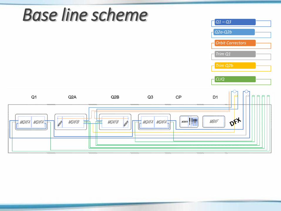
Base line scheme
Orbit Correctors
Trim Q1
Trim Q2b
Q1 – Q3
CLIQ
Q2a-Q2b
Base line schemeOrbit Correctors
Trim Q1
Trim Q2b
Q1 – Q3
CLIQ
Q2a-Q2b
1
1
2
1
2
3
8
1
4
1
1
1
2
2
2
8
2
8
6
6
16
4
2
16
2 5 16 2 3 22
50
1
1
2
1
2
2
3
8
2
6
2
2
8
2
1
6
2
2
8
2
8
2
2
8
2
8
2 5 21 21 22 22
11 +5
9 +3
32 +16
9 +5
2
30 +14
+43
93
Spliced in the tunnelSpliced on surface
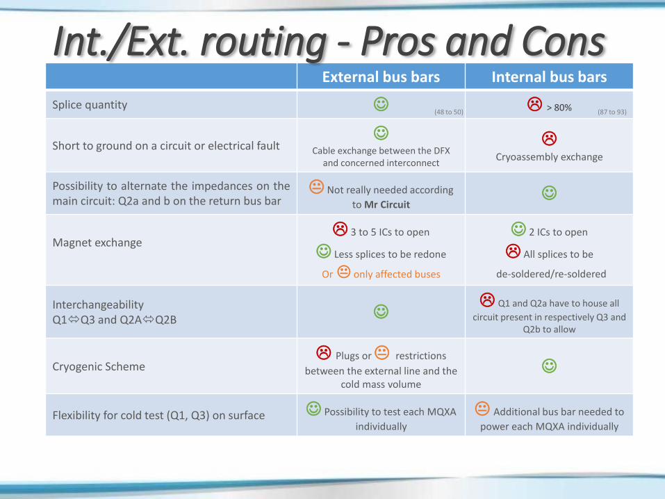
External bus bars Internal bus bars
Splice quantity > 80%
Short to ground on a circuit or electrical fault
Cable exchange between the DFX and concerned interconnect
Cryoassembly exchange
Possibility to alternate the impedances on themain circuit: Q2a and b on the return bus bar
Not really needed according
to Mr Circuit
Magnet exchange 3 to 5 ICs to open
Less splices to be redone
Or only affected buses
2 ICs to open
All splices to be
de-soldered/re-soldered
InterchangeabilityQ1Q3 and Q2AQ2B
Q1 and Q2a have to house all
circuit present in respectively Q3 and Q2b to allow
Cryogenic Scheme Plugs or restrictions
between the external line and the cold mass volume
Flexibility for cold test (Q1, Q3) on surface Possibility to test each MQXA
individually
Additional bus bar needed to
power each MQXA individually
Int./Ext. routing - Pros and Cons
(48 to 50) (87 to 93)
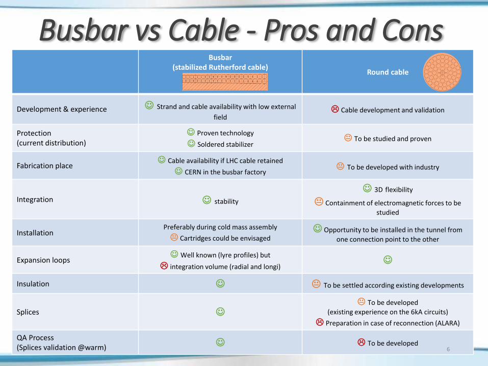
Busbar(stabilized Rutherford cable)
Round cable
Development & experience Strand and cable availability with low external
field Cable development and validation
Protection (current distribution)
Proven technology
Soldered stabilizer To be studied and proven
Fabrication place Cable availability if LHC cable retained
CERN in the busbar factory To be developed with industry
Integration stability
3D flexibility
Containment of electromagnetic forces to be
studied
InstallationPreferably during cold mass assembly
Cartridges could be envisaged Opportunity to be installed in the tunnel from
one connection point to the other
Expansion loops Well known (lyre profiles) but
integration volume (radial and longi)
Insulation To be settled according existing developments
Splices
To be developed
(existing experience on the 6kA circuits)
Preparation in case of reconnection (ALARA)
QA Process(Splices validation @warm) To be developed
6
Busbar vs Cable - Pros and Cons
++ Splices types and validation
+ Well known technology
- Longitudinal space for expansion loops
- Entire cold mass disassembly in case of bus bar problem (may be solved with cartridges?)
- More splices
- Surrounding field
-- Cryoassembly exchange in case of short
-- Ergonomic for splices and ALARA principle
++ Longitudinal space gain for the expansion loops playing with cable flexibility
+ Easier bus exchange in case of problem
- More splices
- Splices types and validation
++ Splices types and validation
+ self magnetic field
? Expansion loop integration
-- Installation
-- Rigidity
++ Less splices
++ Installation in the tunnel
++ Cable exchange in case of a short
? Magnet exchange
? Plugs or restrictions
- Splices types and validation
- Cable development
7
CableBusbarBus technology
Inte
rna
lEx
tern
al
Ro
uti
ng
Bus technology towards Routing
8
Orbit Correctors
Trim Q1
Trim Q2b
Q1 – Q3
CLIQ
Q2a-Q2b
Worst condition:(without considering cables for D1 and CP)
Free section 47.9 cm2
Ext. routing preliminary layout proposal
2
2/1/0
8
2/3
8
To be developed:
34 Nb-Ti strands Ø1.065 mmCu/Sc ratio = 1.6
34 Cu OFE strands Ø1.065 mm
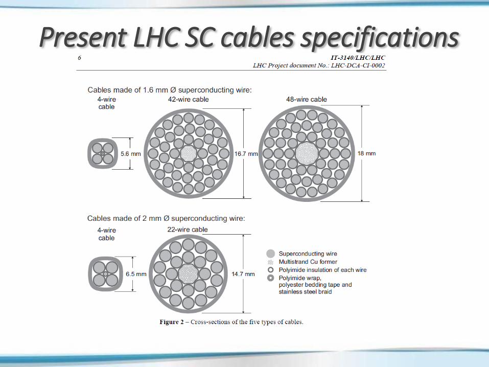
Present LHC 6kA cable:13 Nb-Ti wires Ø0.87 mm
Cu/Sc ratio = 1.36 7 Cu wires Ø0.96 mm
Present LHC 1kA cable:1 Nb-Ti/Cu wires Ø1.6 mm
or34 Nb-Ti strands Ø1.065 mm
Cu Stabiliser equivalent cross section
9
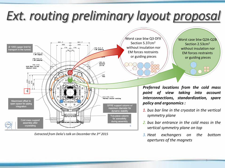
Ext. routing preliminary layout proposal
Extracted from Delio’s talk on December the 3rd 2015
Preferred locations from the cold masspoint of view taking into accountinterconnections, standardization, sparepolicy and ergonomics :
1. bus bar line in the cryostat in the verticalsymmetry plane
2. bus bar entrance in the cold mass in thevertical symmetry plane on top
3. Heat exchangers on the bottomapertures of the magnets
Worst case btw Q2A-Q2BSection 2.53cm2
without insulation norEM forces restraints
or guiding pieces
Worst case btw Q3-DFXSection 5.37cm2
without insulation norEM forces restraints
or guiding pieces
10
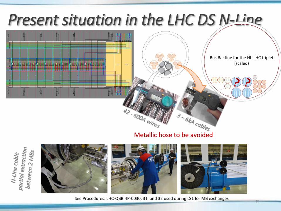
Present situation in the LHC DS N-Line
See Procedures: LHC-QBBI-IP-0030, 31 and 32 used during LS1 for MB exchanges
Bus Bar line for the HL-LHC triplet(scaled)
Metallic hose to be avoided
11
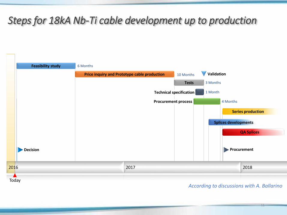
Today
2016 2017
Decision
Validation
Procurement
Feasibility study 6 Months
10 MonthsPrice inquiry and Prototype cable production
3 MonthsTests
Procurement process 4 Months
Series production
Splices developments
Technical specification 1 Month
Steps for 18kA Nb-Ti cable development up to production
2018
QA Splices
According to discussions with A. Ballarino
• Up to 22 buses to be housed (only for the quads and the orbit correctors,CP and D1 to be added and integrated in between Q3 and DFX).
• Using an external routing saves up to 40% splices, simplify consolidationin case of short and simplify the standardization in between Q1-Q3 andQ2A-Q2B.
• Cable eases the expansion lyres design, integration and installation. It ismore appropriate to external routing. But it has to be developed as wellas the splices procedures and tooling (~2 years required).
• Copper stabiliser soldered to Rutherford cable bus bars is a verydeveloped and mastered technology both for production and splicesconnections. LHC cable could be used and is available. This design is notsuitable for long dimensions and require volume for the expansion loops.It does not seem to be very suitable for external routing.
12
Summary
13
Conclusions• Global integration work is going on taking into account environment
constraints and requirements (cryogenics, vacuum, beaminstrumentation…). Despite the last longitudinal increase of theinterconnection length it is not straightforward to design.
• An important part of the integration work is dedicated to the electrical busintegration taking into account the technology and the related constraints(splices quantity and types, ergonomics, ALARA principal…) as well as thebus installation.
• Orbit correctors, trims and CLIQ circuits can be routed externally usingexisting sc cables currently used in the LHC.
• For 18 kA circuits, the “busbars” solution shall be kept as base line until a“cable” type solution has been developed and validated. Internal routing isconsidered inside the cooling holes but an external solution is not excludedtoday, extensive integration work is ongoing. Situation has to be studied atthe level of the Corrector Package and the D1.
• The different intervention scenarios will considered to determine theintervention time and the shielding possibilities in order to support thedifferent choices.
14
Alternate scheme is a bit less consuming in terms of bus, current leads and splicesThe routing seems more adequate for internal routing.
Comments on alternative scheme
The HiLumi LHC Design Study is included in the High Luminosity LHC project and is partly funded by the European Commission within the Framework Programme 7 Capacities Specific Programme, Grant Agreement 284404.
Back-up slides
Alternative schemeOrbit Correctors
Trim Q1
Trim Q2b
Main Quads
CLIQ
1
1
2
1
2
1
8
1
4
1
1
1
1
2
2
8
3
8
1
7
16
6
2
16
1
10 +3
32 +16
12 +6
4 +2
28 +12
+39
Orbit Correctors
Trim Q1
Trim Q2b
Main Quads
CLIQ
2 5 14 3 3 21
18 20 21
48
87
1
1
2
1
2
2 5
2
8
2
2
4
2
8
3
1
6
2
8
3
8
2
8
3
8
21
Additional trim on Q3 or Q2A could be installed on the warm par without further bus bar