Quality guidelines for wood fuels in Finland VTT-M-04712-15 The Bioenergy Association of Finland Finnish Energy Finnish Forest Industries Federation Kaisaniemenkatu 4 A Fredrikinkatu 51-52 B Snellmanninkatu 13 FI-00100 Helsinki, Finland FI-00101 Helsinki, Finland FI-00171 Helsinki, Finland www.bioenergia.fi www.energia.fi www.forestindustries.fi
Transcript
1
Quality guidelines for wood fuels in Finland
VTT-M-04712-15
The Bioenergy Association of Finland Finnish Energy Finnish Forest Industries Federation Kaisaniemenkatu 4 A Fredrikinkatu 51-52 B Snellmanninkatu 13 FI-00100 Helsinki, Finland FI-00101 Helsinki, Finland FI-00171 Helsinki, Finland www.bioenergia.fi www.energia.fi www.forestindustries.fi
2
Foreword
The quality guidelines for wood fuels in Finland are intended for the producers, suppliers and users of
wood fuels to guide them in classifying and determining the quality of wood fuels. These guidelines can
also assist the authorities, for instance, in emissions trading and the application of feed-in tariffs on wood
fuels.
This publication is a translation of the publication: Alakangas, E. & Impola, R., 2014. “Puupolttoaineiden
laatuohje – VTT-M-07608-13 – Päivitys 2014”. EN ISO standards published in 2015 have been updated in
this publication.
In Jyväskylä, October 2015
Eija Alakangas, Technical Research Centre of Finland VTT Ltd.
Literature ..................................................................................................................39
Annex 1 – Classification of wood raw materials (1.1 and 1.2) in accordance with
standard EN ISO 17225-1 ...........................................................................................42
Annex 2 – Examples of product declarations of various wood fuels ............................43
Annex 3 – Determination of particle size ...................................................................45
Annex 4 – Determination of moisture ........................................................................48
Annex 5 – Net calorific value as received – calculation ...............................................49
Annex 6 – Determination of bulk density ...................................................................50
Annex 7 – Example of the sampling and sample preparation for wood fuels ..............52
Annex 8 – Number of increments ..............................................................................53
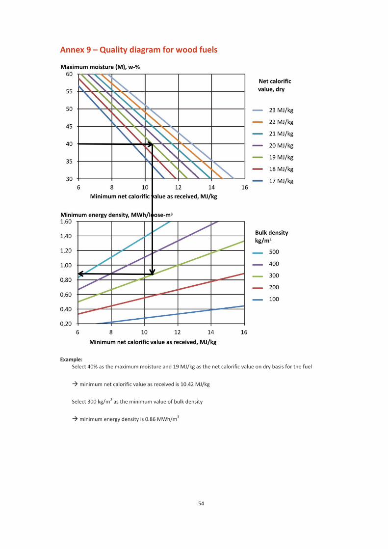
Annex 9 – Quality diagram for wood fuels .................................................................54
Annex 10 – Fuel properties in Finland ........................................................................55
5
1. Introduction
Wood fuels are the most important source of renewable energy in Finland; its share of the total energy
consumption in Finland was 25% in 2014.
The objective of these quality guidelines is to provide unambiguous and clear classification principles for
solid wood fuels, provide guidance for the determination of their quality, and thus act as a tool to enable
efficient trading of wood fuels and to enable good understanding between seller and buyer, and to also
serve the needs of equipment manufacturers. These guidelines will also facilitate authority permission
procedures and reporting.
These guidelines do not include the fuel specification of household wood fuels. The fuel specification of
standard EN ISO 17225-4 can be applied for this purpose. Pellets and briquettes are also excluded from
these quality guidelines; their own quality standards (EN ISO 17225-1, EN ISO 17225-2 and EN ISO 17225-
6) are applied in the determination of their quality.
European and international standards for solid biofuels and the training material of SolidStandards
project's wood chip standard prepared by VTT have been utilised during the preparation of these quality
guidelines. In the years during years 2014 – 2016, the EN standards will be replaced with EN ISO
standards; for this reason, the numbers of the new EN ISO standards are also included in these guidelines.
These guidelines can also be applied in the international trade of wood fuels.
The classification of wood fuels is based on the classification of a raw material's origin, and wood biomass
(Class 1) can be divided into three main groups:
1.1 Woody biomass from forests, plantations and other virgin wood (Annex 1);
1.2 By-products and residues from the wood processing industry (Annex 1); and
1.3 Used wood
These guidelines concentrate on wood fuels sourced from forests, and wood residues from the wood
processing industry. VTT has prepared a separate report and classification guidelines for used wood (Class
1.3). Practical application of the classification of used wood (VTT-M-01931-14, Alakangas, E. et al. 2015).
When determining the quality of "clean" used wood, follow the principles of these guidelines and the
additional quality criteria of the Practical application of the classification of used wood instructions.
If the wood fuel is composed of blends, the percentage shares of the different fuels (as energy) must be
determined before the fuels are mixed, and their percentage shares must be stated. If forest fuels and
used wood or wood residue from the wood processing industry are mixed, the percentage of energy
shares of raw materials from different origins must be stated. With regard to power plants belonging to
the feed-in tariff system, the Energy Authority must approve a plant-specific monitoring plan, in which the
determination of fuel energy contents is described, taking into consideration any mixtures or blends.
6
Furthermore, if wood fuels and peat are mixed together, the Quality guidelines for fuel peat (NT ENVIR
009) must be complied with in addition to these guidelines, and the requirements of emission trading
must be taken into consideration.
7
2. Scope
The purpose of these guidelines is to specify a procedure for reporting and determining the quality and
energy content of wood fuels in an unambiguous and purposeful manner.
3. Normative references
When determining quality, use the procedures listed in Table 1. When determining moisture content,
other moisture content measurement methods (such as rapid moisture meters) can also be used when
separately agreed, if their equivalence with the standard methods can be proven.
Table 1. List of standards related to the determination of wood fuel characteristics1
Property Standard
Moisture coentent as received (Mar) Solid biofuels. Determination of moisture content. Oven dry method (EN ISO 18134-1 parts 1, 2 and 3:2015) Part 1: Total moisture. Reference method. Part 2: Total moisture. Simplified method. Part 3: Moisture in general analysis sample
Ash content (Ad) Solid biofuels. Method for determination of ash content (EN ISO 18122)
Calorific value (qp,net,d) Solid biofuels. Method for the determination of calorific value (EN 14918/EN ISO 18125)
Particle size distribution (P) and fines (F) Solid biofuels. Determination of particle size distribution for uncompressed fuels - Part 1: Horizontally oscillating screen using sieve for classification of samples with a top aperture of 3.15 mm and above (EN 15149-1/EN ISO 17827-1)
Solid biofuels. Determination of particle size distribution for uncompressed fuels - Part 2: Vertically vibrating screen using sieve for classification of samples with a top aperture of 3.15 mm and below. (EN 15149-2/EN ISO 17827-2)
Bulk density (BD) Solid biofuels. Determination of bulk density (EN ISO 17828:2015)
Carbon (C), Hydrogen (H) and Nitrogen (N) content
Solid biofuels. Determination of total content of carbon, hydrogen and nitrogen - Instrumental methods (EN ISO 16948:2015)
Sulphur (S) and Chlorine (Cl) content Solid biofuels. Determination of total content of sulphur and chlorine (EN ISO 16994:2015)
Water soluble chloride (Cl), sodium (Na) and potassium (K) content
Solid biofuels. Determination of the water soluble chloride, sodium and potassium content (EN ISO 16995:2015)
Major elements (Al, Si, K, Na, Ca, Mg, Fe, P and Ti)
Solid biofuels. Determination of major elements, (EN ISO 16967)
Minor elements (As, Ba, Be, Cd, Co, Cr, Cu, Hg, Mo, Mn, Ni, Pb, Se, Te, V and Zn)
Solid biofuels. Determination of minor elements, (EN ISO 16968:2015)
1 the latest published versions of the standards are always used. During 2014 – 2016, the EN standards will be replaced with EN ISO
standards, the numbers of which are also included in the table.
8
Furthermore, the following standards are needed in quality classification, and the application of quality assurance, sampling, and sample preparation:
- EN 15234-1:2011. Solid biofuels. Fuel quality assurance. Part 1: General requirements (referred
to as "quality assurance standard part 1" in the text).
- EN 15234-4:2012. Solid biofuels. Fuel quality assurance. Part 4: Wood chips for non-industrial use
(referred to as "quality assurance standard part 4" in the text).
- EN 14778:2011/EN ISO 18135. Solid biofuels. Sampling (referred to as "sampling standard" in the
text)
- EN 14780:2011/EN ISO 14780. Solid biofuels. Sample preparation (referred to as "sample
processing standard" in the text).
- EN ISO 17225-1:2014. Solid biofuels. Fuel specifications and classes. Part 1: General
requirements. (referred to as "grading standard part 1" in the text)
- EN ISO 17225-4:2014. Solid biofuels. Fuel specifications and classes. Part 4: Graded wood chips
(referred to as "fuel specification standard part 4" in the text)
9
4. Terms and definitions
4.1 Wood fuels
Bark (3121) Bark residue derived from commercial timber by different debarking techniques.
Blend contains intentionally mixed solid biofuels with a known composition or mixture ratio, based on either energy or weight. NOTE: If the mixture ratio is defined based on volume, it must be converted to an energy-based ratio.
Brown chips, dried chips Fuel chips made from dried and flushed felling residue (3113) or a whole tree (3112). NOTE: The raw material of the wood chips has been dried in a pile for no less than six weeks between April and September, significantly reducing the amount of needles/leaves. The concentrations of chlorine or other alkali metals in the wood chips cannot be deduced from their colour.
Chips, wood chips Wood biomass chipped into pieces of a certain size with mechanical cutting blades. The wood chips are rectangular in shape, with their sides typically 5 to 50 mm in length and their thickness small compared to the other dimensions.
Crown mass (3113) By-product from commercial felling, comprising treetops, branches, needles and leaves. Crown mass is a synonym for treetops and branches.
Cutter shavings, planing shavings (3124) Wood residue from planing of timber.
Demolition wood (3232) Used wood arising from demolition of buildings or civil engineering installations. Wood residues from the new construction of corresponding sites are recovered wood (315).
Energy willow (31732) Willow biomass grown for energy use through short rotation forestry.
Forest chips Wood chips produced from forest biomass. In Finland, the term forest chips is used as a general term, referring to delimbed stem (3112), whole tree (3112) and felling residue chips or chippings (3113).
Forest fuelwood (311) Wood fuel produced with a mechanical process directly from wood raw material previously unused for any other purpose. See stump, forest residue chips, forest chips, thinning wood and crown mass.
Forest residue chips (3113) Forest residue chips comprise logging residues left behind in the forest, such as branches and treetops, as well as small-diameter trees and thinning wood and cull trees left at felling sites.
Fresh chips, green chips Fuel chips made from fresh felling residue or whole trees.
2 The corresponding fuel classification number of Statistics Finland is within parentheses. Check the latest Finnish fuel classification
of Statistics Finland from its website at http://www.stat.fi/polttoaineluokitus
10
Fuel chips; energy chips General term for wood chips used in combustion or other energy production, produced with different techniques.
Fuel sawdust; fuel powder Ground solid biofuel with particles typically 1 to 5 mm in size. For example, saw dust (3122) and grinding dust (3124).
Hog fuel Wood fuel that has pieces of varying size and shape and produced by crushing with blunt tools such as rollers, hammers, or flails.
Industrial wood residue Wood biomass residue from wood processing and the pulp and paper industry (bark, , cross-cut ends, edgings, particleboard residue, fibre sludge, grinding dust, plywood residue, sawdust, cutting surfaces, slabs and wood shavings).
Mixture Contains unintentionally mixed solid biofuels, the origin of which is known, but the precise mixture ratio is unknown.
Recovered wood (315) Clean wood residue classified as a solid biofuel or used wood or wood product, which does not contain plastic coatings or halogenated organic compounds and heavy metals. For example, wood residue from new construction, pallets, wood packaging, etc.
Roundwood Delimbed trunk and logs that do not usually meet the requirements set for commercial timber. The term is primarily used for small-diameter timber.
Sawdust (3122) Small particles generated when wood is sawed. NOTE. All three dimensions of the majority of the particles are in the range of a couple of millimetres with the exception of random smaller particles, depending on the saw and the quality of the wood.
Sawmill chips (3123) Barked or debarked wood chips generated as a by-product of the sawmill industry (3123).
Short rotation wood (3173) Woody biomass grown for raw material or energy usage in short rotation coppices with a five-to-eight year rotation (e.g. energy willow).
Stemwood A delimbed part of a tree trunk.
Stump (3114) The part of the stem below the felling cut, including the roots of the tree.
Thinning wood (3112) The part of the forest's growing stock removed during thinning, timber harvested during thinning.
Whole tree (3112) Felled, undelimbed tree, excluding its root system, which contains the stem with bark, branches, and needles/leaves.
11
Wood residue Wood residue refers to wood generated during construction, demolition and renovation activities (3129 or 3232) and wood generated by the wood processing industry that may contain glue, paint, preservatives, and other such substances. Chemically untreated wood residue is classified into Class A, and chemically treated wood into Class B (315), if it does not contain more halogenated organic compounds or heavy metals from treatments with wood preservatives or coatings than virgin wood. Class A and B wood fuels can be classified according to standard EN ISO 17225-1, and the Government Decree on Waste Incineration will not be applied to them. The Solid Recovered Fuels standard (EN 15359) is applied to Class C wood fuels (wood waste), as is the Government Decree on Waste Incineration (151/2013).
Wood residue chips (3123) Chips from industrial barked and debarked wood residue (wood strips, offcuts, etc.) that do not contain painted or otherwise treated wood.
4.2 Sampling, processing and analyses
Combined sample General term for a sample formed by combining the increments taken from the same batch of fuel. A combined sample can also be formed by combining the sub-samples separated from homogenised increments into a single sample.
Delivery lot The wood fuel batch on which the essential, regularly monitored quality requirements for wood fuels are focused. The size of the delivery lot is agreed on a case-by-case basis. The delivery lot can be an individual delivery lot, which is an agreed quantity of fuel (e.g. a package, shipload or truck load), or continuous delivery, where several loads are delivered to the end-user during an agreed period of time (usually daily or weekly delivery). If the delivery lot in continuous delivery is more than 1,500 to 2,000 m
3 in 24 hours, it
is recommended that it should be divided into two or more sub-lots.
General analysis sample A sub-sample of a laboratory sample having a nominal top size of 1 mm or less and used for a number of chemical and physical analyses.
Increment The smallest amount of fuel extracted in a single operation in order to form the combined sample.
Laboratory sample A sub-sample formed of combined samples collected from a delivery batch or its part by homogenisation and division, delivered to a laboratory for analysis. For comparison purposes, several parallel laboratory samples may be formed of the same combined sample, for example for determining moisture content. The laboratory sample may be prepared by the supplier of the sample, or it may be prepared by the laboratory from the delivered combined sample.
Nominal top size In standard EN 15149/EN ISO 17827, the aperture of the sieve with round holes used in the determination of biofuel particle sizes, where at least 95 % by mass of the material passes.
Precision requirement The overall precision required for each significant characteristic of the delivery lot should be agreed between the parties. Should there be no such agreement, the values specified in these guidelines may be used (e.g. ± 2 to 4 percentage units for moisture). The overall precision must be achieved in sampling at a 95 per cent confidence level. Furthermore, the authorities may lay down precision requirements in, for example, the environmental and emission permits.
Sample A quantity of fuel representing a larger quantity, the quality of which needs to be determined.
12
Sub-lot A portion of a lot for which a test result is required. The parties to the agreement may agree to divide the delivery lot into sub-lots in order to improve the assay precision or make the routines of the assay easier or quicker. NOTE: When determining the size of the sub-lot, the sample processing equipment must be taken into consideration, or its size must be separately agreed.
Sub-sample Part of a sample.
The standard EN ISO 16559:2014. Solid biofuels. Terminology, definitions and descriptions contains more
term definitions.
Other terms and classifications
In the European List of Waste (2000/532/EC), wood fuels delivered directly from the forest are classified
as 02 01 07. Correspondingly, wood residues and by-products from the wood processing industry are
classified as 03 01, the subclass 03 01 01 of which includes bark, and subclass 03 01 05 sawdust, shavings,
cuttings, and particle board and plywood residue. Bark and wood residues from paper and pulp
production are classified as 03 03 01. Wooden packaging is found in class 15 01 03, and demolition wood
and wood residues from construction in class 17 02 01.
13
5. Abbreviations, symbols and units of energy
d dry (dry basis)
ar as received
w-% weight percentage
A Designation for ash content, Ad (w-%, dry basis) 3
BD Designation for bulk density as received [kg/m3]
3
Ear Energy density as received, Ear [MWh/m3 loose or stacked volume (amount of energy/volume
unit)]
E Designation for energy density, [MWh/m3, loose or stacked volume]
3
F Designation for amount of fines (w-% as received); fines are separately stated in the particle size
analysis.
M Moisture content as received, Mar [w-%] wet basis 3
P Designation for particle size or particle size distribution as received, designation according to the
main fraction3
qp,net, d Net calorific value at constant pressure on dry basis [MJ/kg]
qV,gr, d Gross calorific value at constant volume on dry basis [MJ/kg]
Q Designation for net calorific value as received, qp,net,ar
[MJ/kg or kWh/kg or MWh/t] at constant pressure 3
NOTE: 1 MJ/kg equals 0.2778 kWh/kg (1 kWh/kg equals 1 MWh/t and 1 MWh/t is 3.6 MJ/kg). 1 g/cm3
equals 1 kg/dm3.
3 The designation symbols are used in the quality classes both in these guidelines and the standards. For designation of chemical
properties, chemical symbols such as S (sulphur), Cl (chlorine), and N (nitrogen) are used and the property class is added at the end
of the symbol.
14
Conversions of units of energy
Unit toe MWh GJ Gcal
toe 1 11.63 41.868 10
MWh 0.086 1 3.6 0.86
GJ 0.02388 0.2778 1 0.2388
Gcal 0.1 1.163 4.1868 1
For example: 1 GJ = 0.2778 MWh, 1 MWh = 3.6 GJ
1 TWh = 3,600 TJ
T = tera = 1,000,000,000,000 G = giga= 1,000,000,000
M = mega = 1,000,000
k = kilo = 1,000
m3= solid cubic metre ( 2.5 m
3 of chips).
1 m3 (solid cubic metres) 2.0 MWh or 7.2 GJ
The net calorific values and the other characteristics and emission factors of the fuels are presented in Annex 10.
15
6. Specification and classification of wood fuels
6.1. Principle of the specification of wood fuels
Wood fuels are specified
1. Based on their origins and the source of their raw materials, classified in accordance with the
woody biomass main class of raw material class 1 of Table 1 of the standard EN ISO 17225-1 (cf.
Annex 1)
2. Based on their traded forms (Table 2) and properties (Tables 3 to 6 of this publication, Section
6.2.3)
Table 2. Classification of traded forms Fuel name Typical particle size Typical production method (EN ISO 17225-1,
Table 2)
Whole tree Wood stem and branches Cut, undelimbed tree, which include also tops and branches, but not stumps and roots, if not separately mentioned
Stem Wood stem without tops and brances
Delimbed small-sized tree or stem
Logging residue Tops and branches Tops and branches, which are cut from stem and also un-merchantable small-sized stem wood
Stump Stump Stump with roots and split into few parts during pulling the stump
Chips 16 …100 mm Cut with sharp tools
Hogfuel Varying Crushing with blunt tools
Bark Varying Debarking residue from trees (shredded or unshredded)
Bundle, bale Varying Lengthwise oriented & bound logging residues or whole trees
Fuel powder < 1 mm Milling
Sawdust 1 … 5 mm Cutting with sharp tools
Shavings 1 … 30 mm Planing with sharp tools
Controlled blends with known energy ratios can be formed of different raw materials. This requires the
determination of the weight and moisture of the fuel. The use of fuel blends is allowed in the feed-in tariff
system, but the Energy Authority requires that the energy content is stated with an accuracy of 7.5% for
fuel fractions in line with the classification of Statistics Finland. Chips from roundwood (3112), forest
residue chips (3113) and hog fuel from stumps (3114) are fuels entitling forest chip power plants to a
feed-in tariff. If these are blended with another solid biofuel that is not subsidised, the energy content of
each solid biofuel must be determined with an accuracy of 7.5%. Blends of just solid biofuels entitling a
feed-in tariff, or just solid biofuels not entitling a feed-in tariff can, on a case-by-case basis, be delivered,
when the net calorific value and moisture of the blend are determined, as long as the method has been
described in a monitoring plan approved by the Energy Authority. It is recommended to always contact
the Energy Authority with regard to mixtures and blends.
See Annex 2 for examples of the product declarations and mixtures and blends of various wood fuels.
16
6.2 Specification of the classes
6.2.1 General principles
The wood fuels most commonly used in Finnish heat and power plants are classified based on their
different characteristics in fuel specification standards parts 1 and 4.
The classification of fuel specification standard part 1 is flexible, allowing the producers and users to
select a suitable class from each property class for their products and plant/application. The classification
of this standard does not tie different properties to each other with the exception of moisture (M) and
calorific value (Q, as received). Some properties are normative (mandatory), some are informative
(voluntary). On a case-by-case basis, some of the informative properties can be agreed to be normative.
The standard is better suited for larger plants. The standard contains separate classification tables for the
following wood fuels commonly used in Finland: wood chips, hog fuel, sawdust, shavings and bark. In fuel
specification standard part 1, the tables for wood chips and hog fuel are combined, and the particle size
classification changes (cf. Table 6 of this publication).
The product standard, or fuel specification standard part 4, concerns wood chips suitable for non-
commercial use, or small-scale applications that are usually ≤ 500 kW (residential, small commercial and
public building applications). The properties are tied to each other forming property classes (A1, A2, B1
and B2). All properties are normative (mandatory).
6.2.2 Classification by the origin of the raw material
Fuel specification standard part 1 also describes a system for classifying the origin of raw materials for the
production of solid biofuels. The first level defines four main biomass types: woody, herbaceous, fruit and
aquatic biomass, and blends and mixtures. The second level classifies the origin and sources of the
biofuels, and levels three and four provide more detailed information on, for example, parts of the tree.
The total of 115 fourth-level descriptions allows the detailed description of the origin of the raw material.
Tables 3 and 5 describe the reporting of raw material quality for wood chips and hog fuel. Annex 1
contains a more detailed classification of wood raw materials.
6.2.3 Classification by properties
The classification based on different properties for wood chips and hog fuel, as presented in Table 5 of the
fuel specification standard part 1, is presented in Table 3 of this publication.
Moisture is the most important factor of wood fuels in fuel trading. Moisture also affects transport costs
and, at the plant, the handling of the fuels and the management of combustion and emissions.
Due to the production and storage methods of forest fuels, the internal moisture deviation of the loads
can be great, which must be taken into consideration during sampling. Seasonal variations must also be
taken into consideration with the delivery moistures. Measures should be taken to alleviate their impact
17
through, for example, correct and careful storage in accordance with the guidelines of the Forest
Development Centre, Tapio.
Table 3. Classification of wood chips and hog fuel according to different properties
Normative propertiest (mandatory, to be states)
Rawmaterial (EN ISO 17225-1) From Table 1 (see Annex 1)
Particle size (Dimensions) – Analysis according to EN 15149-1 (Annex 3)/EN ISO 17827
See Table 4 in this publication
Moisture, M (w-% as received) – Analysis according to EN ISO 18157 (Annex 4)
Classes: M 10, M 15, M 20, M 25, M 30, M 35, M 40, M 45, M 50, M 55 and M 55+ (maximum value to be stated)
Ash, A (w-% dry) – Analysis according to EN ISO 18122 Classes: A 0.5, A 0.7, A 1.0, A 1.5, A 2.0, A 3.0, A 5.0, A 7.0, A 10.0 and A 10.0+ (maximum value to be stated)
Normative (mandatory only for chemically treated biomass (for raw material classes 1.2.2 (Annex 1); 1.3.2 Chemically treated used wood) and voluntary for other biomass)
Nitrogen, N (w-% dry) – Analysis according to EN ISO 16948
Classes: N 0.3, N 0.5, N 1.0, N 1.5, N 2.0, N 3.0 and N 3.0+ (maximum value to be stated)
Chlorine, Cl (w-% dry) – Analysis according to EN ISO 16994
Classes: Cl 0.02, Cl 0.03, Cl 0.05, Cl 0.07, Cl 0.10 and Cl 0.10+ (maximum value to be stated)
Informative properties (voluntary, but recommended to be stated)
Net calorific value, Q (MJ/kg or kWh/kg as received) – Analysis according to EN 14918/EN ISO 18125
minimum value to be stated) (Annex 5 has calculation of net calorific value as received and energy density )
Bulk density, BD (kg/m³ as received) - Analysis according to EN ISO 17828 (Annex 6)
Classes: BD 150, BD 200, BD 250, BD 300, BD 350, BD 400 and BD 450+ (minimum value to be stated)
Ash smelting behaviour (°C) - Analysis according to CEN/TS 15370-1
DT, deformation temperature to be stated
The delivery-specific lower limit of moisture for wood fuels can be agreed to be below 30% only when the
plant receiving the wood fuels has been designed for the safe handling of fuel with the agreed moisture
level.
Table 5 of fuel specification standard part 1 specifies the property classes of wood chips and hog fuels (EN
ISO 17225-1, Table 5) by using particle size classification. In this standard, the grades of wood chips and
hog fuels are presented in the same table. Furthermore, the net calorific value as received or the energy
density is normative (minimum value to be stated). A separate product standard has not been prepared
for hog fuel (e.g. from stumps or plywood residues), but if necessary, fuel specification standard part 4
can also be applied to hog fuel.
18
Table 4. Particle size requirements for wood chips and hog fuel in accordance with standard EN ISO 17225-1. Published with the permission of SFS. Class Main fraction
(at least 60%) mm Coarse fraction (mm) Maximum length for
over-sized particles, mm
Cross sectional area, cm2
on for EN ISO 17225-4 standard
P16S 3.15 <P < 16 <6% >31,5 mm <45 mm <2
P16 3,15 <P < 16 <6% >31,5 mm <150 mm
P31S 3,15 <P< 31,5 <6% >45 mm <150 mm <4
P31 3,15 <P< 31,5 <6% > 45 mm <200 mm
P45S 3,15 <P < 45 <10% >63 mm <200 mm <6
P45 3,15 < P < 45 <10% >63 mm <350 mm
P63 3,15 <P < 63 <10% >100 mm <350 mm
P100 3,15 <P < 100 <10% >150 mm <350 mm
P200 3,15 <P < 200 <10%>200 mm <400 mm
P300 3,15 <P < 300 to be stated
Amount of fines (< 3,15 mm), EN ISO 17225-1
Amount of fines (<3,15 mm) EN ISO 17225-4
F05 < 5 % -
F10 < 10 % For P31S and P45S- classes
F15 < 15 % For P16S class
F20 < 20 % -
F25 < 25 % -
F30 < 30 % -
F30+ > 30 (maximum value to be stated) -
S refers to wood chips that are suitable for smaller plants and can be classified in accordance with standard EN ISO
17225-4.
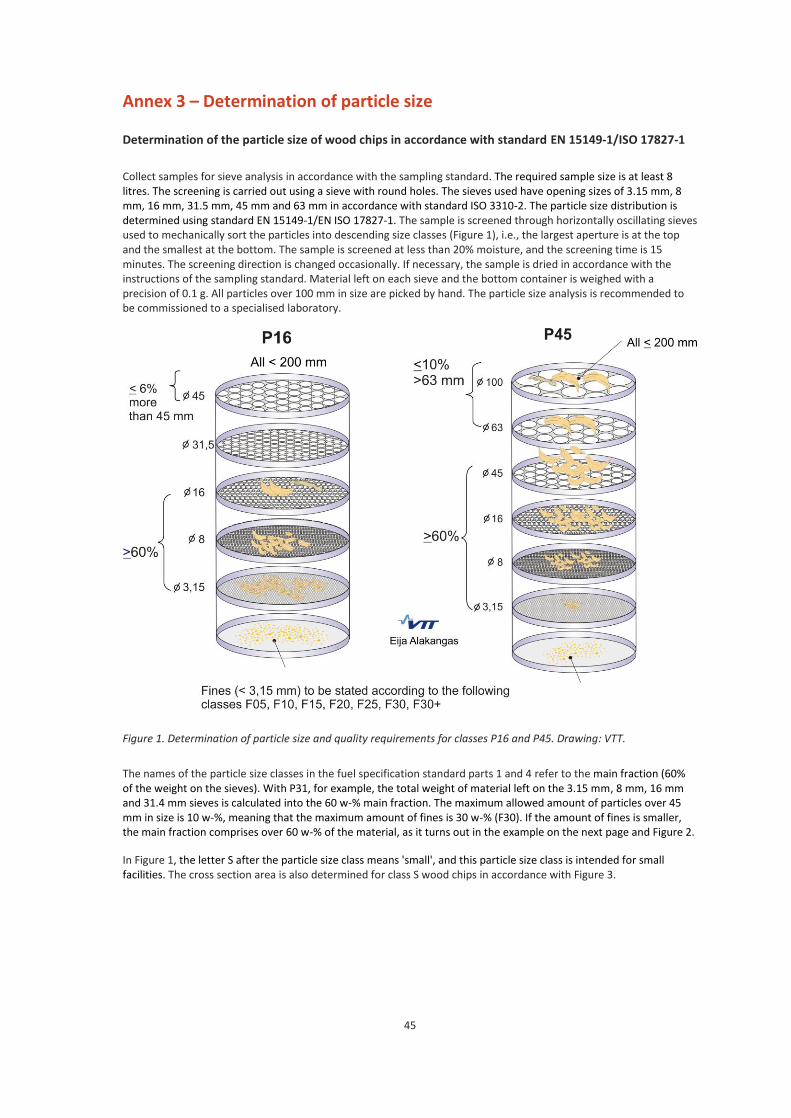
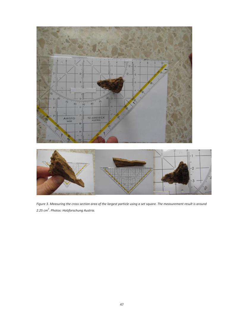
Figure 1 of Annex 3 presents examples of the different fractions of particles size for grades P45, P45S and
P63. Annex 3 also describes a simple method for determining the cross section area. The grade is named
based on the main fraction, and the main fraction must make up at least 60% of the weight of the fuel.
The class of the fines is also separately stated, for example F25.
The fuel specification standard part 4 only allows classes F10 (for classes P31S and P45) and F15 (for class
P16S) for fines. Only the P code is then included in the grade.
19
Wood chips for non-commercial use can be classified into grades A1, A2 or B1, B2 in accordance with fuel
specification standard part 4. The classification is presented in Table 5. The table rows contain the
classified property together with the grade. The grades and their requirements are listed in the columns.
Table 5. Fuel specification of wood chips intended for small plants according to different properties.
Normative properties Grade and values
Raw material (EN ISO 17225-1)
1.1.1 Whole trees without roots (excluding class 1.1.1.3 Short rotation coppice)
1.1.3 Stem wood
1.1.4.3 Logging residues
A1, A2
1.2.1 Chemically untreated by-product or residue from wood processing industry
A1, A2, B1
1.1 Forest wood, plantation wood and other virgin wood (excluding 1.1.5 stumps/root and 1.1.6 bark)
B1
1.2 By-products and residues from wood processing industry (can include chemically treated wood e.g. glued, laminated, painted wood)
1,
1.3 Used wood1
B2
Particle size (Dimensions) – Analysis according to EN 15149-1
Specification according to EN ISO 17225-4 Table 1 and Table 4 in this publication
A1, A2, P 16S, P 31S, P 45S
B1, B2: P 16S, P 31S, P 45S
Moisture, M (w-% as received) - Analysis according to EN ISO 18134-2 A1: M 10 tai M 25
A2: M 35
B1, B2: to be stated
Ash, A (w-% as received) – Analysis according to EN ISO 18122 A1: A 1.0
A2: A 1.5
B1, B2: A 3.0
Net calorific value, Q (MJ/kg or kWh/kg as received) - Analysis according to EN 14918/EN ISO 18125
A1, A2: minimum value to be stated
A2: Q 11.0 or Q 3.1
B1, B2: minimum value to be stated
Bulk density, BD (kg/m³ as received) - Analysis according to EN ISO 17828
A1 : BD 150, BD 200, B250
A2: BD 150, BD 200, B250, B300
B1, B2: value to be stated
Nitrogen, N (w-% dry) - Analysis according to EN ISO 16948
A1, A2: not needed
B1, B2: N 1.0
Sulphur, S (w-% dry) - Analysis according to EN ISO 16994
A1, A2: not needed
B1, B2: S 0.1
Chlorine, Cl (w-% dry) – Analysis according to EN ISO 16994 A1, A2: not needed
B1, B2: Cl 0.05
Major elements (mg/kg dry) – Analysis according to EN ISO 16967
B2: As 1, Cd 2, Cr 10, Cu 10, Pb 10, Hg 0,1, Ni 10 and Zn 100
1 may not contain more halogenated organic compounds or heavy metals than virgin wood (or Table 10 of the
instructions for the practical application of the classification of used wood VTT-M-01931-4, or Table II in Alakangas et.al 2015). Demolition wood is not covered by the standard. 2 Wood chips made from short rotation coppice, which are fertilised by sludges, are classified in class B1.
20
The delivery-specific lower limit of moisture for wood fuels can be agreed to be below 30% only when the
plant receiving the wood fuels has been designed for the safe handling of fuel with the agreed moisture
level.
Fuel specification standard part 1 also presents grades for the most common by-products of the forest
industry (sawdust, shavings and bark). The classification is presented in Table 6.
Table 6. Fuel specification of by-products and residues from the forest industry based on their different
properties
Normative properties Sawdust, shavings Bark
Raw material (EN ISO 17225-1) 1.2.1.3 tai 1.2.1.4 1.2.2.1
1.2.1.5
Particle size (Dimensions)
- Analysis according to EN 15149-1 (Annex 3)/ EN ISO 17827)
no requirements Nominal top size
P 16, P 45, P 63, P 100 and P 200
Moisture, M (w-% as received)
- - Analysis according to EN ISO 18134
Sawdust:
M 10, M 15, M 20, M 25, M 30, M 35, M 45, M 50, M 55, M 60, M 65 and M 65+
1)
Shavings:
M 10, M 15, M 20, M 30 and M 30+
1)
Bark
M 20, M 25, M 30, M 35,
M 40, M 45, M 50, M 55, M 60, M 65 and M 65+
1)
Ash, A (w-% dry)
- Analysis according to EN ISO 18122
A 0.5, A 0.7, A 1.0, A 1.5, A 2.0, A 3.0, A 5.0, A 7.0, A 10.0 and A 10.0+
1)
A 1.0, A 1.5, A 2.0, A 3.0, A 5.0, A 7.0, A 10.0 and A 10.0+
1)
Scredding
- According to standard EN ISO 17225-1 Table 9
not needed shredded or not shredded
Net calorific value, Q (MJ/kg as received) or energy density, E (MWh/loose-m
3) - Analysis according
to EN 14918/EN ISO 18125
Minimum value to be stated
Normative properties (only normative 1.2.2.1 and informative for other biomass)
Nitrogen, N (w-% dry)
- Analysis according to EN ISO 16948
N 0.2, N 0.3, N 0.5, N 1.0, N 2.0, N 3.0 and N 3.0+
1 The maximum value to be stated for grades ending in the plus character (+).
2
Nitrogen and chlorine are normative (mandatory) only for chemically treated wood (class 1.2.2), including painted or varnished wood and particle board or plywood residues, and informative for other wood fuels. In the fuel specification standard part 1, nitrogen and chlorine must also be stated for chemically treated wood. Additionally, Table 10 of the Alakangas, E. 2013 (Guidelines for used wood classification instructions for the application of the classification of used wood) presents additional requirements for the determination of chemical properties. Requirements are also presented in English in Table II (Alakangas, E. & al. 2015).
21
7. Determining the quality grade
7.1 General
The standards applied to the determination of the different properties of wood fuels are listed in Table 1.
The fuel specification of wood fuels used in Finland (wood chips, hog fuel, sawdust, shavings and bark) is
presented in Section 6.2. Different trade forms are used in forest energy deliveries in particular; their
definitions can be found in Section 4.1 and Table 2. Sub-classes of the general designation 'forest chips' in
use include forest residue chips (3113), chips from roundwood (3112), and hog fuel from stumps (3114).
Limit values have been specified for each property on which the wood fuel specification is based, used to
specify the desired grade. Wood fuel is specified by stating the desired quality grade separately for each
property in the fuel specification standard part 1. With regard to the examined property, a batch of fuel
(e.g. a delivery lot or a fuel load) is of a certain quality grade, when the average numerical value of the
property in question is between the specified limit values. For example, a delivery lot with a quality grade
of M35 is comprised of three loads, the moisture contents of which are 34.0 w-%, 35.3 w-% and 33.5 w-%.
The average moisture is then 34.3 w-%, and the lot meets the requirements of grade M35.
In continuous deliveries, it is recommended to monitor the moisture values for each agreed delivery lot or
sub-lot. Other agreed monitored properties, most importantly, net calorific value and ash and chlorine
contents, can be determined. An agreement can be made to monitor these properties on a monthly basis
unless there is a specific reason for more frequent monitoring.
7.2 Moisture (M)
Select the maximum value for moisture content in the delivery lot from the wood fuel class specific quality
grade table.
Wood fuels must be as homogeneous as possible, and particular attention must be paid to moisture
variations. When agreeing on the moisture content of a delivery lot, any seasonal variations for different
wood fuels must also be taken into consideration.
See Annex 4 for a moisture determination method that complies with the moisture determination
standard part 2.
When determining moisture content, other moisture content measurement methods (such as rapid
moisture meters) can also be used when separately agreed, if their equivalence with the standard
methods can be proven. The rapid moisture meters must be calibrated and checked separately for each
fuel in accordance with the moisture determination standards.
22
7.3 Net calorific value as received (qp,net,ar)
The net calorific value as received, or the net calorific value of wood fuel qp,net,ar on a wet basis is
calculated according to formula 1 based on the net calorific value on a dry basis (qp,net,d).
arar
dnet,arnet, MM
qq pp
02443,0)100
100(,, (1)
where
arnet,,pq is the net calorific value (at constant pressure) as received (MJ/kg);
dnet,,pq is the net calorific value (at constant pressure) on dry basis (MJ/kg);
arM is the moisture as received [w-%]; and
0.02443 is the correction factor for the enthalpy of vaporisation (at constant pressure) for water
(moisture) at a temperature of 25 °C [MJ/kg per 1 w-% of moisture].
In fuel specification, the symbol Q is used for the net calorific value as received. The result is given
rounded to the nearest 0.01 MJ/kg. If the calorific value is converted into kWh/kg, the conversion should
not be done until after the calculation. See Annex 5 for an example of the calculation of the calorific value.
7.4 Energy density as received (Ear)
The delivery lot's energy density as received (Ear) is calculated based on the net calorific value as received
and the bulk density as received using Formula 2.
ararnet,ar BDE ,3600
1pq (2)
where
Ear is the solid biofuel's energy density as received (MWh/m3
loose or stacked volume);
arnet,p,q is the net calorific value as received (MJ/kg);
BDar is the bulk density, or the volume weight of the wood fuel as received (kg/m3 loose or stacked
volume); and
3600
1 is the conversion factor for the units of energy (from MJ to MWh).
The result is given rounded to the nearest 0.01 MWh/m3 loose or stacked volume.
23
7.5 Delivered energy (W)
The delivered energy W (in MWh) is calculated using formula 3.
W = 3,6
Q m (3)
where
3,6
Q is the conversion of the net calorific value as received (MJ/kg) to MWh/t; and
m is the mass/weight of the delivered fuel (tonnes)
For small lots and random use, the procedure described above may be too cumbersome; for example,
smaller plants may not always have vehicle scales available. In such cases, the energy of a fuel delivery lot
can be determined as follows:
— measure the volume of the delivered fuel lot in accordance with the Finnish Timber Measurement Act (414/2013);
— determine the bulk density of the fuel (BD) (Annex 6); and
— based on sampling, determine the moisture (M) and net calorific value (Q) of the fuel, or determine the moisture but use a commonly agreed, typical wood fuel class specific net calorific value on dry basis (Alakangas, 2005 or Annex 10).
Other determination methods of delivered energy and their application are separately agreed on a case-
by-case basis. The energy of a delivered fuel lot can be determined at small plants with the help of the
produced energy and the efficiency of the boiler (EN 12952-15:2003).
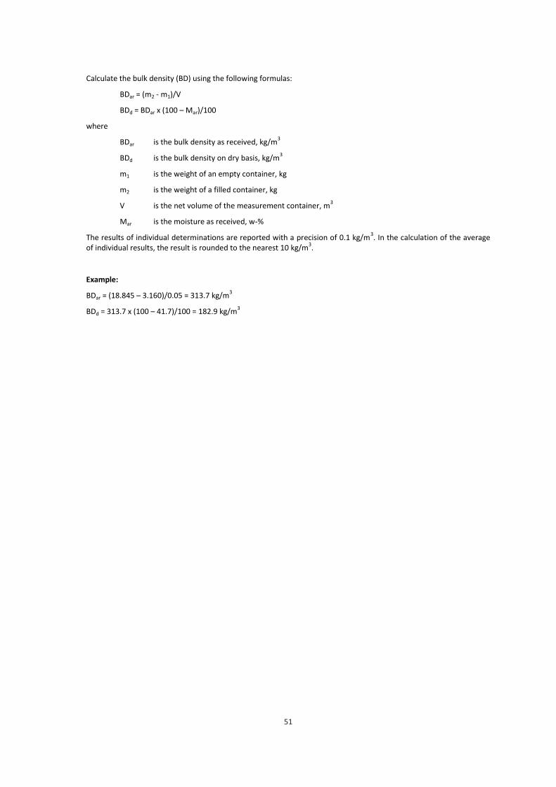
7.6 Bulk density (BD)
The bulk density as received (BD, kg/m3) is obtained by dividing the weighed weight of the load by its
volume. The weighing and volume measurement are carried out in the manner agreed by the supplier and
user in the delivery agreement.
The bulk density of fuel can also be determined for wood chips and hog fuel by using a 50-litre container
in accordance with the bulk density determination standard. The method is described in Annex 6.
7.7 Particle size distribution (P)
The particle size distribution for wood fuels is determined in accordance with the particle size
determination standard part 1. The determination of particle size is described in Annex 3. Plant-specific
combustion and handling systems place limits on both the amount of fines and the maximum dimensions
and number of largest particles. The length and cross section area of the top size are determined for the
coarse fraction only.
24
7.8 Other properties
Ash content and ash melting behaviour are properties that are important with regard to combustion,
particularly for stumps and forest residue chips. Ash content must always be determined during the
determination of the calorific value of stumps and forest residue, unless the parties have agreed
otherwise.
Other properties can also be determined, e.g. the chlorine, carbon and hydrogen content, and the
concentrations of major and minor elements, that specifically apply to the delivered wood fuel and that
might be needed. The chlorine (Cl), sodium (Na) and potassium (K) contents influence the ash melting
behaviour as well as increase the fouling and corrosion risk of the boiler. For this reason, these should be
determined at the beginning of the deliveries and from large fuel lots. With high-pressure steam boilers, it
is recommended to determine these concentrations at least quarterly from each type of fuel. Chlorine
content alone is not enough to indicate the risk level of the examined fuel with regard to fouling and
corrosion of the superheaters. The ratio of sulphur (protective factor) and chlorine (fouling and corrosive)
in the main or secondary fuel is a better indicator. Professional help should be sought for interpreting the
results, as there is no specific chlorine level that would allow one to assume that there will be no
problems with the boiler. The agglomeration of the bed material in fluidised bed boilers has been found
to be mainly caused by the amount of potassium (K), calcium (Ca) and silicon (Si) in the ash, and the bed
material used. Silicates in the ash can react with the potassium in the ash, forming slag (glass like material)
that melts at bed temperatures and may sinter into the bed sand if it is not replaced often enough.
The informative (voluntary) properties mentioned in the standards can be agreed to be normative on a
case-by-case basis.
If the producer or user/buyer measures the fuel properties of delivered fuel, this information should be
available to all parties upon a reasonable request.
25
8. Quality assurance of wood fuels
Quality assurance aims to establish trust in material quality, permanently meeting the agreed customer
requirements that are usually stipulated in the delivery agreement or the product declaration provided by
the supplier. See Annex 2 for sample product declarations. This shows that the agreed quality
requirements are met, which does not necessarily mean that the fuel is of a high quality. In addition to the
fuel quality, the agreed quality requirements cover the quality of the operations of the company
delivering fuel or service (e.g. schedules, logistics and proper documentation). Quality assurance covers
the entire delivery chain. Quality assurance standard parts 1 and 4 and the ISO 9000 system are applied to
quality assurance.
Quality assurance enables the producers and suppliers to create a fuel quality system. Its purpose is to
ensure that
— the delivery chain is traceable;
— the requirements affecting fuel quality are monitored; and
— the end-user/buyer can trust the fuel quality.
Documentation is an important part of quality assurance.
The appropriate production, storage and transport methods have an extremely large impact on the
quality of the delivered wood fuel. They can also ensure that the fuel is stored in correct conditions. All
operators in the fuel delivery chain must avoid taking actions that would degrade fuel quality (including
the user/buyer with regard to final storage).
The operators participating in the transport, handling and storage of wood fuels after production must
document their activities.
Appropriate methods must be used in the production, storage and distribution of wood fuels, and the
recommendations of Tapio, on the harvesting and growing of energy wood. Impurities and over-sized
particles increase in the amount of fines and quality degradation in the fuel lot must be avoided. Examples
of impurities are stones, soil, pieces of metal, plastics, ice and snow. The absorption of moisture into the
wood fuel may degrade its quality.
26
Factors to be particularly taken into consideration:
— weather and climate conditions (e.g. risk of rain or snow) and need for protection during storage;
— storage conditions (e.g. air circulation, moisture absorption, getting wet through the bottom) and the estimated duration of storage;
— storage structure (e.g. prevention of increase in the amount of fines and the rise of the fuel temperature);
— loading and unloading conditions (e.g. impurities, over-sized particles and increase in the amount of fines, smouldering or burning wood fuel);
— the impact of transport on the fuel (e.g. dust formation, particularly adhered dust or fines, road salt);
— uniformity of quality (taking technical and financial limitations into consideration, the quality of the delivered wood fuel must be as homogenous as possible; particular attention must be paid to the moisture differences between individual consecutive loads that must be as small as possible);
— the aim must be to have deliveries with moisture contents that are as homogenous as possible;
— cleanness of all tools and equipment and their suitability for the work stage in question; and
— the competence of the staff throughout the entire delivery chain.
Raw materials or fuels identified as non-conforming at any stage of the production process must be
separated and removed from the production chain. If deviations of the defined requirements are found
during the visual inspection or testing of the raw material or the intermediate/final product, the deviating
lot must be rejected.
Examples of factors indicating product deviations are excessive numbers of over-sized particles, impurities
or fines. A lot can be made to meet the quality requirements by, for example, screening it again. In some
cases, the non-conforming product can be used for a different purpose, or it can be returned to the
delivery chain as raw material.
Smouldering or burning wood fuel must not be delivered to the plants. If smouldering fuel is detected
during unloading, unloading must be interrupted and it must be ensured that smouldering fuel does not
get into the plant's processing system.
27
9. Sampling and the preparation of samples
9.1 General on sampling
Sampling refers to extracting and separating a specific batch suitable for analysis from a larger volume in
such a manner that the sample and the original lot of materials are identical with regard to the desired
properties. In fact, representative sampling means the reduction of both systematic and random errors.
The simplified principles of good sampling and sample processing are:
— the sampling location must be as close to the receiving location of the fuel (change of ownership);
— samples must be taken from freely moving fuel, for example from a falling fuel stream;
— the entire fuel stream or the majority of it must be subjected to sampling;
— several smaller increments are taken from the fuel stream;
— continuous sampling from a partial stream must be avoided; and
— the preparation and dividing of samples must not change the analysed properties.
9.2 Sampling scheme
The basic principle of good sampling is to obtain a representative sample of the entire fuel lot being
tested. Every particle in the lot or sub-lot that the sample represents should have an equal probability of
being selected as part of the sample. The purpose of sample processing is to reduce the sample while
maintaining its representativeness. In order to ensure this, a sampling scheme is required; it is
recommended to include a sampling and processing diagram to the scheme.
We recommend preparing a detailed sampling scheme for each plant that is approved by both the fuel
supplier and the heat or power plant (buyer of the fuel) when making the contract, and which can form a
part of the delivery agreement of the fuel contract in the future. Emissions trade also requires a plant-
specific sampling scheme. When the scheme is being prepared, plant-specific issues to be taken into
consideration include: fuel delivery logistics, vehicle unloading methods, and the requirements and
limitations placed by the plant's reception and handling system on the best possible and reliable sampling
and handling method. Safety issues must also be taken into consideration. Summarised and simple
sampling instructions are also prepared based on the scheme. The sample collectors, who are usually the
vehicle drivers in Finland, will follow these instructions during unloading.
With each heat or power plant (fuel buyer), the following things are agreed in the scheme:
— the sampling location and method best suitable for reception;
— the sampling devices and equipment used;
— the number and volumes of increments;
— the preparation, storage and labelling of samples, the documentation of sampling; and
— unusual occasions´ management.
These quality guidelines provide standard-compliant general instructions for both sampling and the
preparation of samples, based on which plant-specific plans and instructions can be prepared.
28
9.3 Sampling location
In fuel deliveries, the primary sampling location is the fuel's receiving station. In practice, this is often the
reception station, where increments are taken during unloading from the fuel stream falling from the
load, or immediately afterwards from the receiving hopper, the conveyor leaving the reception, or from
the fuel stream falling off the conveyor. The sampling location should be chosen so that a representative
sample of the fuel lot can be obtained most surely and at a reasonable expense. A representative sample
can be most reliably taken from a moving, falling fuel stream.
According to the current experience, the recommended order for the incremental sampling of fuels is as follows:
— moving, continuous fuel stream, primarily at a reception station, but also during at the loading or load transfer stages, for example at terminals;
— mechanically directly from the load, if samplers drilling through the load are developed;
— at the reception station during unloading or immediately afterwards, either from the receiving hopper or the fuel storage yard;
— at the loading stage from the bucket of the loader or the working face of the stockpile; and
— collecting samples from large wood fuel stockpiles or stacks for commercial purposes is not recommended, because obtaining a representative sample is uncertain and requires an undue amount of work.
9.4 Sampling procedure
9.4.1 General
The sampling stage is where the most inaccuracies originate during analysis of results. For this reason,
particular attention must be paid to sampling, and it must be done in a systematic and careful manner.
The best precision can be achieved when sampling is mechanical, which is possible when collecting
samples from a continuous stream of fuel.
Due to the non-homogeneous nature of wood fuels, it is often difficult to collect increments in a manner
that meets the principle of good sampling, according to which each individual particle should have an
equal probability of being selected for the final sample. This is the case particularly when collecting
samples from stationary fuel that has often segregated according to particle size, such as stockpiles, silos,
receiving hoppers, or loads. Collecting increments is easier and more reliable when the fuel is moving, for
example directly from a conveyor or a fuel stream falling off the conveyor, and during the loading and
unloading of the fuel. In summary, samples should be collected from a moving, preferably falling fuel
stream, if this can at all be arranged.
9.4.2 Mechanical sampling
According to the basic principle of mechanical sampling, the increments are collected in such a manner,
that the fuel stream's entire cross section is represented in the sample in accordance with the principle of
averages. This is easiest to implement by collecting the samples either directly from the conveyor belt,
cutting a part of the entire fuel stream or the fuel stream falling off at the end of the conveyor into the
29
sample (Figure 1). This is usually done by the sampling container moving at a constant speed across the
entire fuel stream, cutting the sample from the entire fuel stream. There are several alternative methods
for the mechanical sampler's movement solutions. In both cases, the sampler's aperture must be at least
2.5 times the nominal top size of the material (the round apertures of the sieve where at least 95% by
mass of the fuel passes). The sampling container must be large enough. The fill rate of the sampling
container should be designed to 2/3 (around 67%) of the volume of the entire container in accordance
with the standard.
Figure 1. A cross-belt cutter on the left, and a falling stream sampler on the right. Drawing: VTT/Eija
Alakangas.
Mechanical sampling can also be implemented from scraper and screw conveyors. Increments can be
collected from such intermittent fuel streams by opening the bottom of the conveyor from its entire
width so that the entire intermittent lot of fuel is collected into the sample, for example the fuel lot
between scraper blades.
When selecting the sampling location on the conveyor line, one must ensure that the fuels from different
loads and different suppliers remain separate at the sampling location. Similarly, the sampling interval
must be chosen according to the unloading and conveyor capacity so that the planned number of
increments per load can be collected and representatively spread over the length of the entire load.
Increments can also be collected at the reception station directly from the fuel stream falling off the load
using screw samplers. In mechanical sampling, the increment volumes are large, so sample crushing,
mixing and division equipment have also usually been designed for the automated systems. They produce
a relatively small load-specific sample into a supplier-specific collection bin. After mixing and division,
these combined samples provide a date-specific laboratory sample for analysis.
Because the plant receives loads that are from different suppliers and contain different fuel grades, it
must be ensured that the sampler and sample preparation equipment used are always cleaned after a
30
load-specific sampling sequence. Similarly, it must be guaranteed that the entire sample lot collected (also
including the fines and the largest particles) are included in the sample.
When mechanical sampling and preparing equipment are used, their reliability must be tested, mainly in
order to detect and eliminate any systematic errors. Additionally, the different parties must approve their
deployment for the purpose of sampling on which the fuel pricing is based.
9.4.3 Manual sampling
At most plants, the quality and pricing of fuel are based on manual sampling. The increments are most
commonly taken during unloading either from the fuel stream falling from a rear dump vehicle or
immediately after the unloading, for example from a load-specific fuel pile, receiving hopper or the fuel
storage yard.
Manual sampling can be implemented from conveyor systems using the same principles as the
mechanical sampling methods described above. When implemented correctly, however, they are
cumbersome for continuous use, because when collecting samples directly from a belt conveyor, for
instance, the conveyor must be stopped for the duration of sampling.
A sampling scoop with a long handle (Figure 2) must be used in manual sampling. The diameter of its
aperture in both directions must be at least 2.5 times the nominal top size of the fuel.
Figure 2. Pictured (on the left) a shovel-type sampler for collecting samples from a fuel stockpile and on the right, a three-litre sampling scoop for collecting samples from a moving stream. Photos: Haklog ky and Ismo Tiihonen.
When samples are collected directly from a fuel stream falling from the load, the sampling interval is
determined so that a sufficient number of increments per load can be collected evenly from different
parts of the load. Samples should also be collected from different parts of the fuel stream in the lateral
direction as well. Collecting samples from, for example, the very first particles from a rear dump vehicle
31
and the last scraps should be avoided. Safety must also be taken into consideration during sampling with
regard to the fuel stream falling from the vehicle. We recommend arranging the sampling from "behind a
glass" from a space that is as clean as possible using a sampling scoop with a long handle. Indeed, this has
been successfully implemented at many plants.
When collecting samples from a receiving hopper, for example after the unloading of a side dump vehicle,
the sample collector must walk around the entire hopper and collect samples from different parts of the
hopper while taking safety issues into consideration, so that the sampling is done evenly from different
parts of the entire load.
The fuel load must often be unloaded to the fuel storage field. Samples can then be collected from the
fuel stream falling from a rear dump vehicle in the manner described above. However, it is not always
possible to collect increments from a falling stream, and the samples must be collected after unloading
from a load-specific pile. Then, too, a sampling scoop must be used, and the samples must be collected
from different parts of the pile around it in such a manner that the sampling is done as evenly as possible
from different parts of the dumped load. The fuel has segregated during dumping almost without
exception, with the coarsest particles at the bottom of the pile and the finest matter in the middle and
top of the pile. For this reason, samples must also be taken at regular intervals in the vertical direction of
the pile. Collecting samples from the surface of the pile must be avoided; the samples must be dug from
beneath the surface layer with the sampling scoop. Collecting samples from the absolute bottom and
edges of the pile should also be avoided (Figure 3).
Figure 3. The location of sampling points in a small pile of fuel. Photo: Haklog Ky
Sampling points
32
In manual sampling, the purpose is to be as systematic as possible when collecting load-specific
increments. The main principle is that the samples represent the entire load uniformly with no kind of
segregation or selection taking place during the sampling. The sample collector must not make a selection
with regard to, for example, particle size; instead, even the largest particles and any impurities collected
must be included into the load-specific combined sample.
9.5 The number and volume of increments
The most important factors affecting the number of increments are the actual dispersion of a certain
property, such as moisture, in the lot (load) being sampled, the precision requirement, and the number of
loads belonging to the delivery lot (Annex 8). As the moisture dispersion increases, the precision
requirement will easily raise the number of increments unreasonably high. Moisture deviation in loads
depends on the fuel type, but also the load filling method. For example, when wood is chipped with a
chipper directly into the load, there will be segregation into different parts of the load. In Finland, the
moisture deviations of non-homogeneous forest residue and whole tree chips are larger than with
roundwood chips and hog fuel from stumps.
If sampling is done by fuel load, at least two increments per 50 m3 of loose or stacked fuel must be taken
during continuous fuel deliveries. The minimum numbers of increments for different load volumes are:
— lorry (tractor) minimum of 2 samples
— semi-trailer (< 100 m3) minimum of 4 samples
— tractor-trailer (100 – 160 m3) minimum of 6 samples
(2 from tractor + 4 from trailer)
— container combinations minimum of 2 samples/container
Using these numbers of samples with delivery lots comprising three to five loads, a precision requirement
of around + 3 percentage units for moisture, and in deliveries comprising more than six loads, the
precision improves to around + 2 percentage units (Annex 8).
Because some forest fuels in particular have large in-load moisture deviation, the number of increments
must be at least doubled with small delivery lots (less than 200 m3 loose or stacked volume) and when
determining load-specific properties. For the majority of wood fuels in Finnish conditions, a precision of
around +4 percentage units can be achieved this way.
In the sampling standard, the volume of an increment is based on the particle size of the solid biofuel in
question.
33
The minimum volume of an increment is calculated using formula 4:
Volincr = 0.5 when d95 < 10; (4)
Volincr = 0.05 * d95 when d95 ≥ 10
where Volincr is the minimum volume of an increment in litres, and
d95 is the nominal top size in mm (the round apertures of the sieve where at least 95% by
mass of the fuel passes).
If the nominal top size of the wood chips (d95) is 100 mm, a minimum of 5 litres must be collected for an
increment, and if the nominal top size is 63 mm, a minimum of 3 litres. In practice, the latter particle size
is the most typical for wood chips in Finland.
Note! Although the calculation gives 2.25 litres as the minimum increment volume for a particle size of 45
mm, a sample size of 3 litres should be used for it, too. The nominal top size of hog fuel from stumps is
larger than that of wood chips, giving an increment volume of 5 litres.
In many cases, as many as tens of litres of material, are collected as samples per load, when mechanical
sampling is used. After the sample has been divided, the excess sample material is returned to the feed
line. The size of the final sample is close to the size of an increment collected manually. The sample must
be properly divided to ensure that a representative sample is obtained from each load. Separate testing
approved by both the fuel supplier and user/buyer is recommended in order to ensure that the
mechanical sampling operates reliable and that representative samples are obtained.
9.6 Sample preparation and processing
9.6.1 General
The sampling standard describes both methods that can be used to reduce combined samples into
laboratory and analysis samples, and equipment and methods suitable for mixing and dividing samples.
Certain basic principles must be followed in the reliable preparation of samples:
— the basic principle of division is that the composition of the sample must not change from the original during the different processing steps;
— a careful mixing of the samples improves the reliability of division;
— when the particle size of wood fuels is being reduced (by crushing or grinding), no moisture changes or loss of fines may occur;
— the heating and drying of the sample must be avoided during its processing and storage; and
— the sampling and sample processing equipment and methods used for commercial determination of quality must always be tested in a jointly agreed manner.
34
9.6.2 Combined samples
Combined samples are formed of the delivered fuels for the determination of their properties, primary for
the purpose of determining the price, but also for emissions trading and other separately defined
purposes.
Combined samples are formed for the determination of both fuel moisture and the properties of the dry
matter of the fuel (ash, calorific value, etc.). The combined samples are formed supplier-specifically and, if
necessary, fuel type or delivery location specifically.
Combined samples are always formed of a certain time period. The length of such period is usually
— one day, or a delivery lot for moisture. With large deliveries, e.g. over 2 000 m3 of loose or
stacked volume, it is recommended to form sub-lot-specific combined samples.
— no more than one month for dry matter properties (such as calorific value and ash content)
According to the sampling standard, any of the following methods can be selected in the quality
determination of solid biofuels when forming combined samples and laboratory samples
1. All delivery lot specific increments are put directly into a single container forming a
combined sample that is sent to a laboratory, where a laboratory sample is prepared from it.
2. The increments are mixed together, forming a combined sample from which a laboratory
sample is prepared after mixing and division.
3. Each increment is put into a separate container or bag and sent to a laboratory. The
laboratory combines the samples forming a laboratory sample.
With large deliveries, supplier-specific and, if necessary, fuel type-specific samples are collected in a
delivery-lot-specific manner into a large combined sample container, from which a sample is obtained for
moisture determination once a day after mixing and division. With smaller deliveries, the load-specific
samples can be collected into their own plastic bags or containers that are then delivered to moisture
determination. With wood fuels, the large volumes of the increments are a problem, which means that
the load-specific combined sample must be divided to make it smaller before delivery to a laboratory.
The combined sample for determining the dry matter properties is usually formed of the dried part of
each moisture determination sample by weighing an amount of dried sample proportional to the dry
matter tonnage represented by the sample in question. A corresponding sample can also be extracted
from wet fuel lots proportionally to the size of the delivery lot represented by the sample.
The combined samples must be stored carefully throughout the entire duration of the collection in lidded,
airtight containers in a space that is as cool as possible. One must also ensure that the moisture of the
combined sample collected for moisture determination does not change during storage.
35
9.6.3 Sample preparation
Annex 7 presents the different sample size reduction steps and the sample amounts at different process
stages in accordance with the sampling standard.
The combined sample is divided into a laboratory sample of the required or desired size; with solid fuels,
its volume is at least two litres. The minimum volume is determined by the moisture determination in
accordance with the moisture standard that requires a sample size of at least 300 g of wet material. If
there is also a wish to determine other fuel properties, a larger sample is required. If the calorific value,
ash content and moisture are determined at the same time, around 500 g of material is needed for the
sample. Table 7 presents required sample amounts for different analyses.
Table 7. Sample amounts for typical analyses
Analysis Amount of sample
Basic analysis (calorific value; Q, Ash; A, Sulphur S,
Carbon; C, Hydrogen; H and Nitrogen; N)
About 2 litres (can be analysed also from moisture
content analysis)
Moisture; M at least 300 g about 2 litres
Bulk density; BD about 70 litres, when analysis is carried out with 50 litres
container
Particle size; P at least 8 litres
Large combined samples can be mixed and divided using various quartering and pile methods, the
descriptions of which are found in the sampling standard. Before the combined sample is divided, it is
essential to mix it well. After mixing, the combined sample can be divided using suitable equipment; see
Figure 4 for examples of standard-compliant dividing equipment. As the particle size of wood fuels
increases, the dimensioning of a container type divider must take into consideration that the container
aperture must be large enough for the divider to operate reliably, or 2.5 times the nominal top size.
Particularly when dividing wet fuels, the use of such mechanical dividers requires a significant amount of
work and great care in cleaning and drying the device before processing the next sample.
36
Figure 4. Example of a riffle divider and a rotating divider. Drawing: VTT
If a sample divider is not available, the sample can also be divided manually using the coning and
quartering method presented in Figure 5. Mix the sample carefully all the way to the bottom, and pour
the entire sample into a cone on a table or a suitable plate with a reasonably rapid motion. Then divide
the sample into four parts of equal size using a suitable tool. Select two quarters for the sample in
accordance with Figure 5 (the diagonally opposite quarters). The remaining segments can also be
quartered again, if the remaining sample volume is too large after a single quartering. In such a case the
sample must be carefully mixed before the second quartering.
Figure 5. The coning and quartering method can be used to first divide the sample into four segments, the
diagonally opposite of which are rejected. Quartering is continued until a suitable sample volume is
achieved. Drawing: VTT
37
When the volume of the combined sample increases, we recommend mixing the sample using mechanical
equipment – either specially designed mixers or cement mixers in the plants. After mixing, the process
should be continued using mechanical dividers, such as a riffle box. At all stages of sample processing,
care must be taken to avoid segregation by particle size (coarse particles, fines/ash content). There is also
a need to ensure that the equipment is cleaned of both fuel and moisture residues between uses.
When manual sampling is used, the previous sample collector must clean the sample processing table,
and the next sample collector must ensure that no sample materials or moisture remain on the table from
the previous sampling.
38
10. Legal provisions governing measuring
The Finnish Timber Measurement Act (414/2013) is applied to the delivery, work and contract
measurement of unrefined timber. The unrefined timber referred to in the Act comprises timber
assortments manufactured from stemwood, bark, branches, stumps and roots regardless of the purpose
of use. The allowed processing methods are: cutting, chipping and crushing. Industrial wood chips from
sawmills and plywood plants, and sawdust lots of over 20 m³ of loose volume are also covered by the Act.
The Act came into force on 1 July 2013, and it has been applied to the measurement of energy wood
assortments since 1 January 2014.
Measurements carried out in accordance with the Timber Measurement Act yield the final results in units
of volume, weight or quantity. The determination of, for example, solid volume, bulk volume, weight or
dry weight, and the required measurements including moisture measurement, are covered by the Act.
The Act is not applied to the determination of energy content or calorific value.
The Timber Measurement Act contains provisions on what must be agreed upon regarding the
measurement, who performs the measurement, how the reliability of the measurement is ensured, what
are the requirements on the measurement methods and equipment, how the measurements are
documented, and how the measurement results are reported to the measurement parties. Furthermore,
the Act lays down the organisations and procedures for the enforcement of the Act, development of
measurement operations, resolution of measurement disputes, and appeals.
Decree of the Ministry of Agriculture and Forestry (12/13) also lays down provisions on the requirements
on measurement methods and equipment, and carrying out measurements. The decree includes, for
example, the measurement principles and content of the measurement methods used in timber
measurement (measurement method groups), procedures for ensuring the reliability of the
measurements, the maximum allowed deviations in the measurements, and the general requirements for
measurement equipment.
The Act stipulates that the general conversion factors related to timber measurement are issued by a
decree of Natural Resources Institute Finland (1/2013). The decree includes conversion factors related to
harvester measuring, the measuring of timber logs and piles, and conversions between weight and
volume.
The Timber Measurement Act is applied to the weighing of timber using automatic weighing instruments.
The Act on Measurement Equipment (707/2011) is applied to the weighing of timber using non-automatic
weighing instruments; it is the general act for measuring.
39
Literature
Act on Measurement Equipment, 707/2013. Statutes of Finland, 17.6.2011.
http://finlex.fi/fi/laki/alkup/2011/20110707
Alakangas, E. 2014. Käytöstä poistetun puun luokittelun soveltaminen käytäntöön – VTT-M-01931-14
[Practical application of the classification of used wood]. 51 p. Finnish Energy, Finnish Forest Industries
Federation and the Bioenergy Association of Finland. In Finnish
Alakangas, E. 2005. Properties of wood fuels used in Finland, Technical Research Centre of Finland, VTT
Project report PRO2/P2030/05, Jyväskylä 2005, 89 p. + app. 10 p. (www.vtt.fi)
Alakangas, E., Erkkilä, A. & Heikkinen, A. 2013. SolidStandards project, Wood chips – training materials,
April 2013, 44 p. in Finnish
Alakangas, E. & Impola, R. 2013. Puupolttoaineiden laatuohje, VTT-M-07608-13 – päivitys 2014. 41 p. + 21
p. Finnish Energy, Finnish Forest Industries Federation and the Bioenergy Association of Finland.
Alakangas, E., Koponen, K. Sokka, L. & Keränen, J. Classification of used wood to biomass fuel or solid
recycled fuel and cascading use in Finland, Book of Proceeding Bioenergy 2015, p. 79 – 86, For Boost for
Entire Bioenergy Business, 2 – 4.9.2015, Jyväskylä, Finland
Decree of the Finnish Forest Research Institute on the general conversion factors related to timber
measurement. Decrees of Ministries, Decree of the Finnish Forest Research Institute 1/2013, DocNo.
1.1.7 Segregated wood from gardens, parks, roadside maintenance, vineyards, fruit orchards and driftwood from freshwater
1.1.8 Blends and mixtures
1.2 By-products and residues from wood processing industry
1.2.1 Chemically untreated wood by-products and residues
1.2.1.1 Broad-leaf with bark
1.2.1.2 Coniferous with bark
1.2.1.3 Broad-leaf without bark
1.2.1.4 Coniferous without bark
1.2.1.5 Bark (from industry operations)
1.2.2 Chemically treated wood by-products, residues, fibres and wood constituents
1.2.2.1 Without bark
1.2.2.2 With bark
1.2.2.3 Bark (from industry operations)
1.2.2.4 Fibres and wood constituents
1.2.3 Blends and mixtures
Examples:
Fresh/green logging residues, spruce – 1.1.4.2
Stumps/roots, spruce – 1.1.5.2
Stemwood, mixture of broad-leaf and coniferous (majority broad-leaf) – 1.1.3.1 & 1.1.3.2
Sawdust, spruce – 1.2.1.4
Cutter shavings, pine – 1.2.1.4
Bark, spruce – 1.2.1.5
Blend of cutter shavings, sawdust and bark – 50 vol-% 1.2.1.4 and 50 vol-% 1.2.1.5
43
Annex 2 – Examples of product declarations of various wood fuels
The product declaration is prepared according to the minimum values, taking the typical range into consideration.
Example 1. Product declaration for wood chips from delimbed stemwood
Product declaration based on standard EN ISO 17225-1
No
rmat
ive
Property Unit Property grades
Raw material - 1.1.3.1 Delimbed stemwood, broadleaf
Location Kyyjärvi, Finland
Particle size, P mm P 45, F 10
Moisture, M w-% M 40
Ash, A w-% dry A 1.0
Info
rmat
ive
Bulk density, BD kg/m3 BD 250
Energy density, E MWh/loose m3 E 0.80
The quality grade according to the fuel specification standard part 4 is A2.
Example 2. Product declaration for wood chips from logging residue
Product declaration based on standard EN ISO 17225-1
No
rmat
ive
Property Unit Property grades
Raw material - 1.1.4.2 Fresh/green, logging residue, coniferous
Location Forssa, Finland
Particle size, P mm P 31, F 25
Moisture, M w-% M 55
Ash, A w-% dry A 5.0
Info
rmat
ive
Bulk density, BD kg/m3 BD 400+ (408)
Net calorific value as received, Q
MJ/kg Q 7.0
Example 3. Product declaration for hog fuel from stumps
Product declaration based on standard EN ISO 17225-1
No
rmat
ive
Property Unit Property grades
Raw material - 1.1.5.2 Stumps/root, coniferous
Location Forssa, Finland
Particle size, P mm P 45, F 20
Moisture, M w-% M 45
Ash, A w-% dry A 10+ (11,5)
Info
rmat
ive
Bulk density, BD kg/m3 BD 300
Net calorific value as received, Q
MJ/kg Q 8.3
Example 4. Product declaration for sawdust
Product declaration based on standard EN ISO 17225-1
No
rmat
ive
Property Unit Property grades
Raw material - 1.2.1.4 Sawdust, coniferous
Location - Hämeenkyrö, Finland
Moisture, M w-% M 55
Ash, A w-% dry A 0.5
Net calorific value as received, Q
MJ/kg Q 7.1
Info
rmat
ive
Bulk density, BD kg/m3 BD 300 (estimation)
Screening - not screened
44
Example 5. Product declaration for bark
Product declaration based on standard EN ISO 17225-1 N
orm
ativ
e
Property Unit Property grades
Raw material - 1.2.1.5 Bark, coniferous
Location Hämeenkyrö, Finland
Particle size, P mm P 45, F 20
Moisture, M w-% M 55+ (60)
Ash, A w-% dry A 10.0+ (10,5)
Net calorific value as received, Q
MJ/kg Q 5.5
shredding - shredded
Example 6. Product declaration for a blend of cutter shavings, sawdust and bark
Product declaration based on standard EN ISO 17225-1
No
rmat
ive
Property Unit Property grades
Raw material - 20w-% 1.2.1.4 Cutter shavings, 12w-% sawdust, coniferous, 68w-% 1.2.1.5 bark, coniferous
Location - Jyväskylä, Finland
Particle size, P mm P 45, F 20
Moisture, M w-% M 50
Ash, A w-% dry A 3.0
Net calorific value as received, Q
MJ/kg Q 8.5
Scredding shredded
Info
rmat
ive
Bulk density, BD kg/m3 Cutter chips BD150
Sawdust, BD300 Bark, BD350
The blend in Example 6 is made at a terminal by piling the different wood fuels in turns, beginning with cutter shavings, followed by sawdust and bark in layers of a couple of tens of centimetres. The layers will be compacted when more fuel is loaded on top of them. To determine the amount of blend, the loaded amount is calculated based on the volume of the loader bucket. The weight is estimated using the bulk densities of each wood fuel. The bulk densities are measured in accordance with Annex 6 before mixing. Typical values can be used as the calorific value. When the blend is delivered to the buyer, moisture samples are usually taken from the load at the buyer's reception station in addition to weighing the load. The calorific value is analysed from the moisture sample.
In example 6 the blend comprises 36 vol.-% of cutter shavings (moisture ca. 10.0 w-%), 11 vol.-% of sawdust (moisture 55.0 w-%) and 53 vol.-% of bark (moisture 60%). The net calorific values of the different fractions as received are listed in Table 1. Ten bucket loads of cutter shavings, three of sawdust and 15 of bark are loaded. If the bucket has a scale, the weight of each lot can be measured, and the energy content calculated using the calorific value. If the bucket does not have a scale, and the volume of one bucket load is 9 m
3, the weights are calculated using the
densities mentioned in Example 6. The calculated average calorific value is 8.42 MJ/kg. When the calorific value from the plant is compared to this value, the final result can be corrected proportionally to the energy contents.
Table 1. Calculating the energy content of the blend (Example 6)
Fuel Amount, bucket size m
3 x amount
m3
Amount, m3 x bulk
density (kg/m3),
kg
Net calorific value as received, MJ/kg
Energy amount, MJ
Cutter shavings 9 x 10 = 90 m3 90 x 150 =13 500 kg 16.86 227 610
Sawdust 9 x 3 = 27 m3 27 x 300 = 8 100 kg 7.25 58 725
Bark 9 x 15 = 135 m3 135 x 350=47 250 kg 6.21 293 423
Blend, total Total 252 m3 Total 68 850 kg
average bulk density 273 kg/m
3
Average 8.42 MJ/kg Average moisture content 49.0 w-%
579 758
45
Annex 3 – Determination of particle size
Determination of the particle size of wood chips in accordance with standard EN 15149-1/ISO 17827-1
Collect samples for sieve analysis in accordance with the sampling standard. The required sample size is at least 8 litres. The screening is carried out using a sieve with round holes. The sieves used have opening sizes of 3.15 mm, 8 mm, 16 mm, 31.5 mm, 45 mm and 63 mm in accordance with standard ISO 3310-2. The particle size distribution is determined using standard EN 15149-1/EN ISO 17827-1. The sample is screened through horizontally oscillating sieves used to mechanically sort the particles into descending size classes (Figure 1), i.e., the largest aperture is at the top and the smallest at the bottom. The sample is screened at less than 20% moisture, and the screening time is 15 minutes. The screening direction is changed occasionally. If necessary, the sample is dried in accordance with the instructions of the sampling standard. Material left on each sieve and the bottom container is weighed with a precision of 0.1 g. All particles over 100 mm in size are picked by hand. The particle size analysis is recommended to be commissioned to a specialised laboratory.
Figure 1. Determination of particle size and quality requirements for classes P16 and P45. Drawing: VTT.
The names of the particle size classes in the fuel specification standard parts 1 and 4 refer to the main fraction (60% of the weight on the sieves). With P31, for example, the total weight of material left on the 3.15 mm, 8 mm, 16 mm and 31.4 mm sieves is calculated into the 60 w-% main fraction. The maximum allowed amount of particles over 45 mm in size is 10 w-%, meaning that the maximum amount of fines is 30 w-% (F30). If the amount of fines is smaller, the main fraction comprises over 60 w-% of the material, as it turns out in the example on the next page and Figure 2.
In Figure 1, the letter S after the particle size class means 'small', and this particle size class is intended for small facilities. The cross section area is also determined for class S wood chips in accordance with Figure 3.
46
The informative annex of the particle size determination standard includes the determination of the median value (d50). It is a value that divides the distribution into two equally sized parts and that is graphically the intersection point of the cumulative size distribution curve at the 50% horizontal line.
Example:
The following logging residue weights have been measured from sieves complying with the ISO 3310-2 standard:
Fraction Screen size Mass of fuel, w-%
Measured fraction (requirement)
Particle size class
1
Cumulative amount %
Fine fraction < 3,15 mm 24.2 24.2% (F25) F25 24.2
Main fraction 3,15 – 8 mm 34.2 64% ( > 60 %)
P16 58.4
8 – 16 mm 29.8 88.2
16 – 31,5 mm 8.3 96.5
Coarse fraction 31,5 – 45 mm 0.7 3.5% (< 6 % more 31.5 mm)
P16 97.2
45 – 63 mm 2.8 all less than 150 mm
100
63 – 100 mm 0 P16 100
< 100 mm 0 100 1
Select the smallest particle size class that meets the quality requirements.
The logging residue in the example is suitable for particle size class P16 and fines for F25.
Figure 2. Different fractions of logging residue chips with particle size P16, F25. Drawing: VTT
47
Figure 3. Measuring the cross section area of the largest particle using a set square. The measurement result is around
2.25 cm2. Photos: Holzforschung Austria.
48
Annex 4 – Determination of moisture
Determining the moisture of wood chips in accordance with standard EN ISO 18134-2
Figure 1. Moisture samples in a drying oven. Photo: Labtium Oy
Collect the samples in accordance with the sampling standard. The basic principle of sample reduction is that the composition of the sample must not change from the original during the different steps. The sample is reduced in accordance with the sample preparation standard. Mix the sample before preparation. Weigh the sample using scales with a precision of at least 0.1 g. Also weigh the empty drying container (= m1).
The sample size must be at least 300 g for wood chips and hog fuel. The sample layer must not be too thick. The particle size of the sample during moisture determination should be no more than 31,5 mm (nominal top size). Mark the sample with a unique identifier.
Dry the sample in an oven at a temperature of 105°C ± 2°C. The oven's ventilation valve (exhaust valve) must be open, and the humid air must be able to exit through it without hindrance. Monitor the temperature regularly.
Place the sample into the oven immediately after weighing (weighing value m2). Be careful not to lose the sample materials! Do not position the samples too compactly, touching the walls, or on the bottom of the oven. Use an oven mitt when taking the sample out of the oven to prevent burns.
Dry until the sample reaches a weight that no longer changes, but not longer than 24 hours!
Weigh the sample immediately after taking it out of the oven (weighing value m3). Then, turn off the oven. Calculate the moisture (Mar) wet basis using the following formula: Mar = (m2-m3)/(m2-m1) x 100 Mar moisture as received, w-% m1 weight of the drying container, g m2 the combined weight of the drying container and sample before drying, g m3 the combined weight of the drying container and sample after drying, g The result is reported with a precision of 0.1 percentage points. One determination is enough. Example: Mar = (582.47 – 456.96) / (582.47 – 281.13) x 100 = 41.7 w-%
49
Annex 5 – Net calorific value as received – calculation
The net calorific value of dry matter can be determined in accordance with standard EN 14918/EN ISO 18125, or a jointly agreed typical net calorific values for different woods. The typical calorific value can be obtained from, for example, Annex B of the fuel specification standard part or Alakangas, E. 2005, Properties of wood fuels used in Finland, VTT, Project report PRO2/P2030/05 (www.vtt.fi)
The net calorific value (at constant pressure) as received qp,net,ar (wet biofuel) can be calculated, when the net calorific value on dry basis qp,net,d and moisture as received Mar are known using the following formula:
qp,net,ar = qp,net,d x (100-Mar)/100 – 0.02443 * Mar
The result is reported with a precision of 0.01 MJ/kg.
Example:
Basic information:
Raw material: Logging residue 1.1.4.2
Net calorific value on dry basis:
Analysis in accordance with EN 14918/EN ISO 18125 qp,net,d = 19.50 MJ/kg
Typical value (Table B.3; EN ISO 17225-1): qp,net,d = 19.20 MJ/kg
(typical range, Table B.3; EN ISO 17225-1): (qp,net,d = 18.5 – 20.5 MJ/kg)
Moisture:
Analysis in accordance with EN 14774-2/EN ISO 18134-2 Mar = 59.7%
Net calorific value as received:
qp,net,ar = 19.50 x ((100-59.7)/100) – 0.02443 x 59.7 = 6.40 MJ/kg (based on an analysis)
qp,net,ar = 19.20 x ((100-59.7)/100) – 0.02443 x 59.7 = 6.28 MJ/kg (based on the use of a typical calorific value)
1 MJ/kg equals 0.2778 kWh/kg. The calculations use the unit MJ/kg, and the conversion to kWh/kg is done at the end of the calculation.
Calculation of energy density
If a unit of volume is used for the deliveries (m3
loose or stacked) and the bulk density has been measured, the energy density is calculated is follows:
Ear = (qp,net,ar/3600) x BDar
In this example, the bulk density was 379.0 kg/m3
Ear = 6.40/3600 x 379.0 MWh/m3 = 0.67 MWh/m
3
50
Annex 6 – Determination of bulk density
Determining the bulk density of wood chips in accordance with standard EN ISO 17828
The ratio between the container height and diameter must be between 1.25 and 1.50. Use a so-called large container for wood chips and hog fuel with a volume of 50 litres (0.05 m
3). Weigh using scales with a precision of at least 10 g.
Also weigh the empty container. Perform the sampling and sample preparation in accordance with the corresponding standards. Determine the sample's moisture content as received in accordance with EN ISO 18134-2 immediately after the bulk density has been determined. In this way, the determination of bulk density and moisture can be combined, which is commonly done by smaller plants.
Mix the sample (sample amount a bit less than 70 litres). Fill the container by pouring from 20–30 cm above the top edge of the container until the highest possible heap has formed.
The filled container is dropped three times by letting it drop freely from a height of 15 cm to a wooden plate. Ensure that the container hits the wooden plate vertically. Refill the empty space created in the container.
Remove any extraneous material using a small batten moving over the container in swinging motions. If the sample contains coarse matter, all particles preventing the batten from moving freely must be removed by hand. If the removal of large particles makes largish pits in the levelled surface, fill them and repeat the removal of extraneous material.
Weigh the filled container. Combine the used sample with the unused sample matter, repeat the procedure, and then repeat the entire procedure at least once.
Photos: VTT/Eija Alakangas
51
Calculate the bulk density (BD) using the following formulas:
BDar = (m2 - m1)/V
BDd = BDar x (100 – Mar)/100
where
BDar is the bulk density as received, kg/m3
BDd is the bulk density on dry basis, kg/m3
m1 is the weight of an empty container, kg
m2 is the weight of a filled container, kg
V is the net volume of the measurement container, m3
Mar is the moisture as received, w-%
The results of individual determinations are reported with a precision of 0.1 kg/m3. In the calculation of the average
of individual results, the result is rounded to the nearest 10 kg/m3.
Example:
BDar = (18.845 – 3.160)/0.05 = 313.7 kg/m3
BDd = 313.7 x (100 – 41.7)/100 = 182.9 kg/m3
52
Annex 7 – Example of the sampling and sample preparation for wood
fuels
53
Annex 8 – Number of increments
The minimum number of increments is calculated using the formula presented in the sampling standard
n = the minimum number of increments;
PL= the desired overall precision including sampling, preparation and determination (analysis) at a 95% statistical
confidence level;
VI = the primary variance between the increments (= square of the internal deviation, sd2)
N = the number of sub-lots, or number of loads in Finland; and
VPT= variance of preparation and determination.
The overall sampling precision is affected most by both the delivered fuel lot's internal moisture deviation and its size, or the number of loads. The internal moisture deviations of various Finnish forest fuels have been analysed taking into consideration both seasonal variations and the geographical location of the plants (Järvinen, 2012). The deviations were largest with logging residue chips and whole-tree chips. The figure below presents the effect of the number of increments on the overall precision of sampling with regard to moisture. The parameter is the size of the delivery lot N (1 to 5 loads). The average deviation in logging residue chips during different seasons has been used as the internal moisture deviation (sd = 4.92 percentage points).
Figure 1. The dependency of the number of increments (n) on the desired overall precision (PL) with the sub-lots (N) as
parameters with logging residue chips using the average seasonal deviation. Photo: VTT.
— When six increments are taken from a load, the overall precision is a bit under + three percentage units, when the delivery lot comprises three loads
— The precision approaches + 2 percentage units when the delivery lot increases to five loads.
— The changes in overall precision are large with small delivery lots (one to two loads) when the number of increments must be doubled in order to keep the overall precision tolerable.
— Variations in the internal deviation do not affect the shape of the graphs; with larger deviations, the family of curves in the figure moves upwards, i.e., the sampling precision decreases.
— For some forest fuel deliveries, it is characteristic that the seasons affect the moisture deviation in the delivery lot; for example, the deviation is significantly larger during winter than during summer.
54
Annex 9 – Quality diagram for wood fuels
Example: Select 40% as the maximum moisture and 19 MJ/kg as the net calorific value on dry basis for the fuel
minimum net calorific value as received is 10.42 MJ/kg
Select 300 kg/m3 as the minimum value of bulk density
minimum energy density is 0.86 MWh/m3
55
Annex 10 – Fuel properties in Finland
Table 1. Typical calorific values, energy densities, moisture contents, bulk densities and ash contents of different fuels
Fuel Net calorific value MWh/t (moisture 0 %) (MJ/kg) qp,net,d
Moisture (Mar)
Net calorific value as received MWh/t (MJ/kg) qp,net,ar
Sources: Alakangas. E. 2005. Properties of wood fuels used in Finland. VTT Project report PRO2/P2030/05 Alakangas, E. & Virkkunen, M. Biomass fuel supply chains. EUBIONET II