International Journal of Computer Networks & Communications (IJCNC) Vol.3, No.3, May 2011DOI : 10.5121/ijcnc.2011.3307 94 DESIGN AND ANALYSIS OF SD_DWCA–AMOBILITYB ASED CLUSTERING OF HOMOGENEOUS MANETST.N. Janakiraman 1 and A. Senthil Thilak2 1, 2 Department of Mathematics, National Institute of Technology, Tiruchirapalli-620015, Tamil Nadu, India 1 [email protected], tnjraman2000 @yahoo.com 2 [email protected]A BSTRACTThis paper deals with the design and analysis of the distributed weighted clustering algorithm SD_DWCA proposed for homogeneous mobile ad hoc networks. It is a connectivity, mobility and energy basedclustering algorithm which is suitable for scalable ad hoc networks. The algorithm uses a new graph parameter called strong degree defined based on the quality of neighbours of a node. The parameters are so chosen to ensure high connectivity, cluster stability and energy efficient communication among nodes of high dynamic nature. This paper also includes the experimental results of the algorithm implementedusing the network simulator NS2. The experimental results show that the algorithm is suitable for high speed networks and generate stable clusters with less maintenance overhead. KEYWORDSMobile ad hoc networks, SD_DWCA, Connectivity, Strong degree, Cluster Stability 1.INTRODUCTIONMobile Ad hoc Networks [MANETs], which are otherwise called as multi-hop networks or peer-to-peer networks are those formed by a series of autonomous mobile hosts interlinked by means of bandwidth-constr ained wireless links with limited battery power. Ad hoc networks, as their name indicates, are unpredictable with frequently changing topology. Each node has a circular transmission range and those nodes which lie within this range alone can communicate with this node. The transmission range of all the nodes can either be uniform or may vary and the nodes may either be of similar or of dissimilar nature. If the transmission range of all the nodes is uniform or the nodes are of same nature, i.e., they are of same architecture then the network is termed as a Homogeneous network. Otherwise, it is referred to as a heterogeneous network. The management and control functions of the network are distributed among the nodes in the entire network. As the network is highly decentralized, all network activities including topology discovery, keeping track of topological changes due to mobility, transmitting and maintaining routing information and efficient usage of battery power must be executed and monitored by the nodes themselves. Since these networks are highly dynamic and ad hoc in nature, executing these control functions becomes a bottle-neck. In order to perform this management and control operations and to communicate messages among nodes having no permanent bonding, it is essential to set up a virtual backbone and this is accomplished by the process of clustering. Clustering is the process of grouping nodes based on certain strategies and the above mentioned functions can either be distributed among the nodes in each cluster or performed by the leader nodes/Cluster-heads of each cluster rather than distributing throughout the network. This
Transcript
8/6/2019 Quality of Service Provisioning in MANET Using a Cross-Layer Approach for Routing
This paper deals with the design and analysis of the distributed weighted clustering algorithm SD_DWCA
proposed for homogeneous mobile ad hoc networks. It is a connectivity, mobility and energy based
clustering algorithm which is suitable for scalable ad hoc networks. The algorithm uses a new graph parameter called strong degree defined based on the quality of neighbours of a node. The parameters are
so chosen to ensure high connectivity, cluster stability and energy efficient communication among nodes
of high dynamic nature. This paper also includes the experimental results of the algorithm implemented
using the network simulator NS2. The experimental results show that the algorithm is suitable for high
speed networks and generate stable clusters with less maintenance overhead.
K EYWORDS
Mobile ad hoc networks, SD_DWCA, Connectivity, Strong degree, Cluster Stability
1. INTRODUCTION
Mobile Ad hoc Networks [MANETs], which are otherwise called as multi-hop networks or
peer-to-peer networks are those formed by a series of autonomous mobile hosts interlinked bymeans of bandwidth-constrained wireless links with limited battery power. Ad hoc networks, astheir name indicates, are unpredictable with frequently changing topology. Each node has a
circular transmission range and those nodes which lie within this range alone can communicatewith this node. The transmission range of all the nodes can either be uniform or may vary and
the nodes may either be of similar or of dissimilar nature. If the transmission range of all thenodes is uniform or the nodes are of same nature, i.e., they are of same architecture then thenetwork is termed as a Homogeneous network. Otherwise, it is referred to as a heterogeneous
network. The management and control functions of the network are distributed among the nodes
in the entire network. As the network is highly decentralized, all network activities includingtopology discovery, keeping track of topological changes due to mobility, transmitting and
maintaining routing information and efficient usage of battery power must be executed and
monitored by the nodes themselves. Since these networks are highly dynamic and ad hoc in
nature, executing these control functions becomes a bottle-neck. In order to perform thismanagement and control operations and to communicate messages among nodes having no
permanent bonding, it is essential to set up a virtual backbone and this is accomplished by theprocess of clustering.
Clustering is the process of grouping nodes based on certain strategies and the above mentioned
functions can either be distributed among the nodes in each cluster or performed by the leadernodes/Cluster-heads of each cluster rather than distributing throughout the network. This
8/6/2019 Quality of Service Provisioning in MANET Using a Cross-Layer Approach for Routing
International Journal of Computer Networks & Communications (IJCNC) Vol.3, No.3, May 2011
95
reduces, to a great extent, the information exchange between the network nodes and theinformation to be maintained by each node thereby reducing the overheads incurred. Severalalgorithms are available for clustering of mobile ad hoc networks [1], [12], [15], [18], [21], [24].
Particularly, classified as mobility-only-based algorithms [5], [13], [16], power-only-based [2],
[18], [19] and combination-based algorithms [7-9], [18], [21], [22]. The algorithm discussed inthis paper is a combination-based algorithm, proposed in [23]. In our algorithm, a new graph
parameter called strong degree is defined and in addition, we consider two other parameters, namely,
mobility metric [introduced by Xing et al. in 20] and battery power.
The rest of this paper is organized as follows. The basic definitions and graph theoretic
terminologies used in this algorithm are given in section 2 and section 3 outlines a review of theexisting clustering algorithms. Section 4 includes the basic idea which led to the development of
the algorithm and the objectives of the algorithm. Section 5 gives the description and section 6the complexity analysis of the algorithm. Section 7 says how the clusters can be ranked based
on their cluster members. Section 8 includes the simulation study and finally, Section 9concludes the paper.
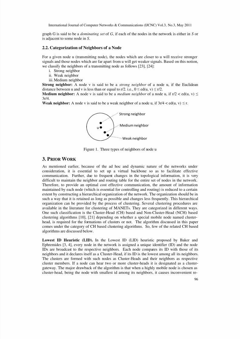
2. BASIC DEFINITIONS AND TERMINOLOGIES
In this paper, the mobile ad hoc network taken under consideration is assumed to behomogeneous, i.e., each node has uniform transmission power. Hence, from now on, by anetwork, we mean a Homogeneous Mobile Ad Hoc Network unless otherwise specified. In a
general wireless network, to identify the neighboring nodes, each node broadcasts a “Hello”message containing information like its position in the terrain, node id etc. Those nodes which
are within the transmission range of the transmitting node can receive the message and theyeither send an acknowledgement to the sender or simply store the information received from the
sender to identify and record details about their neighbors. These recorded data, in turn can be
utilized for clustering and/or routing. As the nodes are mobile, each node periodically shouldsend and receive the hello messages, to keep track of their neighbor info. Thus, the neighbor set
is periodically updated for each node. This communication strategy can in general be modelled
by using an undirected graph as follows.
2.1. Graph Theory vs. MANET
A graph G is defined to be an ordered pair (V, E), where V is a non-empty set of nodes and E
denotes the set of edges/links between different pairs of nodes in V . Any set of devices which
are capable of interacting with each other can be modeled by using graphs. To represent anygiven network using a graph, say G, the set of all nodes in the network is taken as the node set
V , where two nodes are made adjacent, if the corresponding two nodes are within the
transmission range of each other, i.e., each is in the neighbour set of the other. The graph G thusobtained is referred to as the underlying graph or the network graph.
If u and v are any two nodes in G, then d(u, v) denotes the least number of hops to move from u
to v and vice versa and is referred to as the Hop-distance between u and v and ed(u, v) denotesthe Euclidean distance between u and v. Thus, in a homogeneous network, for a given
transmission range r, two nodes u and v can communicate with each other if and only if theyare at an Euclidean distance less than or equal to r, i.e., ed(u, v) ≤ r . For a given node u, N(u) denotes the set of neighbors of u , i.e, N(u) is the set of those nodes which are 1-hop away from u
and its cardinality is defined as the degree of u, which is denoted by deg(u). The hop-distancebetween u and its farthest node in G is called the eccentricity of u in G and is denoted by ecc(u),
i.e., )},({max)()(
vud ueccGV v∈
= . The minimum and maximum eccentricities of G are defined
respectively as radius [r(G)] and diameter [d(G)] of G. A subset S of the node set V(G) of a
8/6/2019 Quality of Service Provisioning in MANET Using a Cross-Layer Approach for Routing
International Journal of Computer Networks & Communications (IJCNC) Vol.3, No.3, May 2011
97
clustering and undesired cluster-head changes. Secondly, since this algorithm is inclined tochoose nodes having smaller IDs as cluster-heads, the smaller ID nodes suffer from batterydrainage leading to short lifespan. Further, the id is not assigned based on any practical
constraint and hence, the election of cluster-heads is not meaningful.
Highest Degree Heuristic (HD). The highest degree (HD) heuristic is based on the
connectivity between a node and its neighbors and was proposed by Gerla et al. [11, 17]. Thisconnectivity value of a node is broadcast to all its neighbors and if a node has higher
connectivity value than its neighbors, then it is elected as a cluster-head and a cluster is formedwith the elected cluster-head and its neighbors. Any tie in cluster-head election is broken by
node IDs. Cluster-gateways are formed with the nodes capable of hearing two or more cluster-
heads. Since this algorithm doesn’t restrict the number of nodes that can be handled by acluster-head, the heads run out of power very quickly.
Mobility-only-based Clustering Algorithms. In MOBIC given by Basu et al. [5], the relative
mobility metric is introduced, in order to form stable clusters and is defined as the logarithm of the ratio of two successive received signal strengths and an aggregate relative mobility metric M
is computed for each node by taking the variance (with respect to zero) of the entire set of pair-
wise relative mobility values of the node and each of its neighbors. Then it follows the sameprocedure as in LID heuristic to form clusters with node ID in LID replaced by the value M
here. Hence, it has all the drawbacks of LID. The same problem is met with the MobDHopclustering algorithm given by Er and Seah [13].
Power-only-based Clustering Algorithms. In general, for any cluster-head election procedure,a node with higher battery power is considered to be a better candidate to play the key role of a
cluster head. In that way, the algorithms given in [18], [19] consider battery power as the onlysystem parameter for electing cluster-heads. But, as the mobility of nodes is not considered inthe election, the possibility of re-clustering is still high when elected cluster-heads have high
mobility.
Combination-based Clustering Algorithms. Chatterjee et al. [7, 8] and Choi and Woo[9] have
given clustering algorithms using multiple-metrics. In each of these algorithms, they consideredmobility and battery power as two of the important metrics together with other parameters. In
all these algorithms, the average speed is computed by considering the (x, y) positions of thenodes at various instants (from initial time t = 1 to t = T, where T is the time at which the
algorithm is executed or weight is computed) and is used as the mobility metric. The (x, y)
positions are obtained using GPS, the accuracy of which is not ideal for fine computing and theoperations of which could drain the limited battery power of the node quickly. Further,
regarding power metric, Chatterjee et al. [7, 8] used the cumulative time period for which a
node acts as a cluster-head for computing battery power. But, this cannot accurately reflect thecurrent level of battery power because a busy node (i.e., a node which might have lost much of
its energy in just transferring or forwarding the control packets) may almost run out of power
without being a cluster-head [20]. Choi and Woo [9] used consumed battery power as a metricfor computing battery power. Thus, integrating these two (mobility and power) parameters
together with the other parameters, node weight is defined for each node in those algorithms andthe clustering procedure is similar to that of HD heuristic except that here node weight is used in
the place of node degree.
4. MOTIVATION AND OBJECTIVE OF THE ALGORITHM
In the algorithm analyzed in this paper, we consider three important parameters, namely, battery
power, mobility measure and strong degree. Though there are several algorithms available inthe literature, starting from the highest degree heuristic, almost all the above mentioned
8/6/2019 Quality of Service Provisioning in MANET Using a Cross-Layer Approach for Routing
International Journal of Computer Networks & Communications (IJCNC) Vol.3, No.3, May 2011
98
algorithms use the degree of a node as an important parameter and priorities were given tonodes having highest degree. While choosing the nodes with highest degree for acting ascluster-head, all the strong, medium and weak neighbours of a node contribute for the highest
degree of that node. But, there may be some nodes, say, u and v such that the number of strong
neighbours of u is less than that of v and the number of medium (and weak) neighbours of u isgreater than that of v with deg(u) > deg(v). Thus, as per the strategies used in the existing
algorithms, on comparing u and v, u becomes eligible for CH election, even though it has lessernumber of strong neighbours than v. But, at a later instant, due to mobility, the node u may lose
its eligibility of remaining as a CH. This makes the cluster structure less stable and the cluster
members attached to that cluster have to be re-affiliated or sometimes re-clustering has to be
done.
This is because, the nodes which are at the rim of the circular transmission range, (weak neighbors) of the cluster-head and the nodes which are considerably far away from the cluster-
head (medium neighbors) are more likely to move away from the cluster-head, compared tostrong neighbors. This factor highly affects the stability of the clusters generated and this leads
to frequent cluster-head updates, re-affiliation, re-clustering etc. and hence cluster-maintenancecost is also increased. This problem motivated us to start defining this concept. Considering
such a situation, we’ve defined a new degree called strong degree and this was included as oneof the main parameters in SD_DWCA [23]. Apart from this, we also include the mobility of thenodes and the battery power for CH election. For, if a CH is allowed to continue its status for a
longer period, then it will lead to battery drainage and hence we should continue with re-affiliation or re-clustering. Hence, to avoid excessive usage of a CH, battery power is
considered for selecting cluster heads. With these three parameters, the algorithm is developedwith the following objectives.
1. The network nodes are partitioned into different groups of various sizes, so as to form a
hierarchical organization of the network.2. The clusters have to be stable as long as possible, but, without excessive battery
drainage.3. The cluster formation and maintenance overhead should be minimized.
4. The cluster-heads should not be overloaded.
5. During the cluster set up and maintenance phase, the load should be distributed amongall the nodes in the network.
6. Re-affiliations should be minimized.7. Re-clustering should be avoided as much as possible. At times of necessity, re-
affiliations are allowed instead of re-clustering to reduce the cost of cluster
maintenance.8. The algorithm should overcome the problem of scalability.
9. The generated clusters should facilitate hierarchical routing.
5. STRONG DEGREE BASED DISTRIBUTED WEIGHTED CLUSTERING
ALGORITHM (SD_DWCA)
5.1 Metrics
5.1.1. Strong Neighbour Set - Let G = (V, E) be the underlying network graph and u ∈V(G).The Strong neighbour set of u is defined to be the set of all strong neighbours of u and is
International Journal of Computer Networks & Communications (IJCNC) Vol.3, No.3, May 2011
99
In the same way, the medium neighbour set (denoted by MN(u)) and weak neighbour set (denoted by WN(u)) are defined using the respective definitions given in section 2.2. Themedium degree of a node u ∈V(G) is the cardinality of the set MN(u) and is denoted by d mn(u)
and the weak degree of a node u ∈V(G) is the cardinality of the set WN(u) and is denoted by
d wn(u).
In general, the degree of a node is the sum of the number of strong neighbours, mediumneighbors and weak neighbours, i.e., deg(u) = |SN(u)| + | MN(u)| + |WN(u)| = d sn(u) + d mn(u) +
d wn(u).
5.1.3 Mobility metric:
Here, we adopt the mobility measure defined by Xing et al. [21]. For each node u in the
network, after receiving two successive hello messages from its 1-hop neighbors, the relativemobility metric with respect to each of its 1-hop neighbors is computed using the formula (1).
If node v is a neighbor of node u, then the relative mobility metric of u with respect to v is
denoted by Rv(u), and is defined as follows:
Rv(u) =v
v
r
r
2
1
-------------------------(1)
Here, vr 1 and vr 2 denote the two successive signal strengths received by u from v. This received
signal strength can be read from RSS indicator. The signal strengths received vr 1 and vr 2 may
be like either vr 1 < vr 2 or vr 1 = vr 2 or vr 1 > vr 2 . Thus, we have the following cases.
Case i: Rv(u) < 1
If Rv(u) < 1, then it indicates that the nodes u and v move close to each other.Case ii: Rv(u) > 1
If Rv(u) > 1, then it indicates that the nodes u and v move away from each other.
Case iii: Rv(u) = 1
If Rv(u) = 1, then it indicates that either the nodes u and v do not move at all or they move
with the same speed in the same direction.
In this way, the relative mobility value of a node is computed with respect to each of itsneighbors and the root mean square deviation of these values taken from the value 1 (as given in
equation (2)) is used as the mobility measure of u and is denoted by M(u).
M(u) =deg(u)
(u))R(u)(R2
N(u)v
v −∑∈
, ---------------------------(2)
where (u)R = 1.
In the cluster-head election procedure, to maintain the stability of elected cluster-heads, the
cluster-heads are expected not to move away from their cluster members. Hence, the valueRv(u) of each node u with respect to each of its neighbours is preferred to be less than or equal
to 1 and therefore (u)R = 1, instead of actual mean. Suppose, some neighbour of node u has
sent more than two periodical hello messages, but u didn’t receive two of them successively or ureceived only one of them, then that neighbour is excluded in the weight calculation of node u.
This is because, that particular neighbour of u might have moved away from u, i.e., might be a
weak neighbour of u or there might be signal attenuation.
8/6/2019 Quality of Service Provisioning in MANET Using a Cross-Layer Approach for Routing
International Journal of Computer Networks & Communications (IJCNC) Vol.3, No.3, May 2011
100
5.1.4. Power Metric:
To consider the battery level of each mobile node, and to ensure that the cluster-heads are notexcessively utilized, i.e., used until they get completely drained out, we use a metric denoted by
RE(u), which denotes the residual energy/remaining battery power of node u. If IE(u) denotesthe initial energy assigned to node u and CE(u) denotes the consumed battery power of u, then,
RE(u) = IE(u) – CE(u). To compute this value, each node records its remaining battery powerafter sending and receiving every message.
5.2 Node Weight
To elect CHs, each node is initially assigned a weight computed using formula (3).
W(u) = RE(u)αM(u)][1/ α(u)dα 32sn1 ++
-----------------------(3)
Here, the constants 1α , 2α and 3α denote the weighing factors. In almost all types of
applications, it is natural to give equal weightage to all the three parameters which we’ve
considered. So, we choose the values of the three weighing factors as 1/3, so that their sum isunity. If in some application, any of these parameters have to be given special importance thenthe weighing factors can be chosen accordingly.
Here, the first parameter, strong degree is chosen to maintain stability of cluster-heads andthereby, the stability of the generated clusters, the second parameter is chosen to make thealgorithm to be adaptive to mobility and the third to choose a node which can afford to play the
key role of a cluster-head for a longer period, compared to others.
The algorithm includes two phases, namely, cluster formation and cluster maintenance asexplained below.
5.3 Cluster Formation
At any instant t, Let Gt denote the graph corresponding to the underlying topology of the nodes
at that particular instant and V(Gt) denote the node set of Gt. It is assumed that all nodes sendand receive data with equal transmission range and the nodes are moving with velocity ranging
in the interval [0, Vmax] and they are free to move in any direction. The status of each node isinitially set to “UNKNOWN”.
5.3.1. Initial Cluster Formation.
Step 1: Each node periodically sends and receives hello messages. The hello messages are sentwith a predefined broadcast interval (BI).
Step 2: While sending a hello message, a node sends its node id, (x, y) position (to categorize theneighbor). Meanwhile, the sender should record its remaining battery power.
Step 3: A node, upon receiving a hello message, stores the neighbor info received. Also the
received signal strength and the time stamp are recorded.Step 4: As specified, if a node fails to receive two successive hello messages after a neighbor has
sent atleast three messages, then the neighbor is excluded in weight computation.Step 5: With the above information, each node computes its own weight after a fixed duration.
This time gap is specified to allow the hello messages to be sent and received by eachnode from all its neighbors.
Step 6: After computing the weight value, each node broadcasts this weight value to all itsneighbors.
Step 7: Then, each node compares its weight with that of its neighbors. If the weight of a nodeis maximum, then it declares itself as a cluster-head and sends a message
“CLUSTER_INFO” together with its node id, to all its neighbors.
8/6/2019 Quality of Service Provisioning in MANET Using a Cross-Layer Approach for Routing
International Journal of Computer Networks & Communications (IJCNC) Vol.3, No.3, May 2011
101
Here, each node has an active participation in the cluster formation process and hence thealgorithm is referred to as distributed.
Step 8: On receiving the message CLUSTER_INFO, if the current status of the receiving node is
UNKNOWN, then it becomes a cluster member of the sender and stores the sender’s id
as its cluster-head id and in turn broadcasts the message to all its neighbors. Otherwise,if it is already a member of another cluster and if the weight of its cluster-head is less
than that of the sender, then it changes its affiliation, i.e., changes its cluster-head id asthe id of the sender.
Step 9: Finally, the clusters generated are obtained as output.Step 10: After making all comparisons, nodes still in the status of “UNKNOWN” are collected
separately and are termed as “Critical nodes”. The critical nodes are then subjected to anadjustment procedure.
5.3.2. Formation of Adjusted Clusters.
Let C denote the set of critical nodes obtained after initial cluster formation. If some (atleasttwo) of the critical nodes are adjacent, then they are allowed to form a cluster on their own. In
this case, among all the neighbors, the one with higher weight is chosen as the Cluster-head and
the rest are considered as cluster members. If still there are left out nodes, then they become
cluster-heads on their own. This process distinguishes our algorithm from the other existingalgorithms. In most of the existing algorithms, if there is any node left uncovered, then either re-
clustering takes place [7], [8] or the nodes are themselves declared as cluster-heads [9]. But, inthe proposed algorithm, the nodes are grouped as far as possible, thereby reducing the number
of clusters generated.
5.4 Cluster Maintenance
In general, while dealing with mobile networks, the position (position in the terrain) and status
(cluster-head/member/critical node, in our case) of the nodes at the time of cluster formationwill change in due course, because of nodes’ mobility. Hence, in order to provide a valid
hierarchical structuring to facilitate an efficient routing, it is necessary to consider this topology
change and discuss the behavior of the clustering procedure in such cases. This leads to the
cluster maintenance phase. The change in the initial topology may be caused due to node failurebecause of battery drainage, addition of a new node into network, link failure, link establishment. Hence, we discuss the behavior of our algorithm in all these four cases
separately.
Case i: Node failure
As per the clustering procedure given in [23], a node failure means either the drainage of thebattery power of a node below a fixed threshold value or complete exhaustion of battery power
of a node. Generally, the idea of clustering is adopted to properly utilize the resources of the
nodes such as battery power, limited bandwidth etc, in data transmission. Hence, the cluster-heads are allowed to play a key role than the non-cluster heads. This leads to higher usage of
battery power by cluster-heads rather than the other nodes. So, we assume that only the cluster-
heads have a greater chance of getting drained out quickly and we deal with the failure of
cluster-heads. To avoid cluster-heads being overloaded or to avoid excessive usage of battery bya subset of the nodes, we fix a threshold value for energy/battery power. During the formationof clusters, each cluster-head periodically checks whether its residual energy is above the
threshold value. When it goes below the threshold value, the cluster-head sends a resignationmessage and all the nodes in the cluster should affiliate themselves to other existing clusters.
Hence, each cluster member of such a cluster will send a find_CH message to all its neighboring
cluster heads. Any cluster-head which receives this message will in turn send anacknowledgement message to the senders and includes that node in its list of cluster members.
8/6/2019 Quality of Service Provisioning in MANET Using a Cross-Layer Approach for Routing
International Journal of Computer Networks & Communications (IJCNC) Vol.3, No.3, May 2011
102
If a sending node receives a cluster-head acknowledgement message from more than one node,then it gets attached to the one having maximum weight. When a node gets completely drainedout, it will be isolated from communication. But, the periodical check up of available battery
power of the maximum utilized nodes will avoid such a situation as far as possible. This also
increases the network life time.
Case ii: Node addition
There is a chance for a new node entering into the network. In such a case, the newly enteringnode should attach itself to an existing cluster. Hence, after identifying its neighbors by passing
hello messages, it broadcasts the find_CH message and fixes its appropriate status as explainedin the previous case.
Case iii: Link failure
There is also a possibility for the nodes which are already grouped into some cluster to move
outside the boundary of the cluster. Then, such a node also sends a find_CH message and gets
attached to some existing cluster as in case i.
Case iv: Link establishment
When there is a possibility for nodes attached to one cluster moving outside its existing clusterboundary, the same will move closer to some other cluster boundary. This will induce new link establishments and also continuous movement of the nodes will also induce frequent link
establishments and failures. To handle new link establishments, each cluster-head should
periodically update its neighbor table. If a cluster-head finds a new node in its neighbor table, it
checks whether its weight is greater than that of the new node. If it is greater, it continues itsstatus and adds the new neighbor as its cluster member. If not, it will check in its neighbor table
whether there are many (quantified as atleast two) nodes which are common neighbors of boththe existing cluster-head and the newly added neighbor, then the current cluster-head will
interchange its role with the newly added neighbor. The nodes in the current cluster, which are
non-neighbors of the newly elected cluster-head will get attached to the appropriate neighboring
clusters by passing find_CH message.
If an execution of the above clustering procedure yields no critical nodes, then the clustering is
said to be a perfect clustering. On the other hand, if there are some critical nodes left out and thenumber of critical nodes can be reduced to zero by the adjustment procedure, then the clustering
is said to be a fairly perfect clustering [23].
6. COMPLEXITY ANALYSIS
To perform the analysis, it is assumed that the continuous run time of the algorithm is dividedinto discrete time steps. Here, one time step is defined as the time duration for the sending of a
message (control packets) by a sender and a complete processing of it by the recipient [6]. The
approach adopted in this paper is motivated by the theoretical analysis of DMAC made in [6],
[13]. It is also assumed that any message transmitted by a sender is successfully received and
processed by all its recipients in one time step. We compute the total overhead (message/time)incurred in three steps as follows: Overhead due to hello protocols, cluster formation and clustermaintenance.
Let MH, MCF, MCM denote the message complexities due to hello protocol, cluster formation,
cluster maintenance respectively and TH, TCF, TCM respectively denote the time complexities dueto hello protocol, cluster formation, cluster maintenance and M and T denote the overall
message and time complexities respectively. The total message complexity of the algorithm isthe sum of MH, MCF and MCM. Similarly, T is the total of TH, TCF and TCM.
8/6/2019 Quality of Service Provisioning in MANET Using a Cross-Layer Approach for Routing
International Journal of Computer Networks & Communications (IJCNC) Vol.3, No.3, May 2011
103
6.1 Overhead due to Hello Protocols
Each node periodically broadcasts the hello messages to keep track of its knowledge about itsneighbours, at a fixed predefined interval BI. Thus, the frequency of hello messages broadcastby a node is T/BI, where T is the total running time of the algorithm, until which each node has
to maintain its neighbour data. Hence, on the whole, N*(T/BI) hello messages are to be
transmitted, for the entire set of nodes to maintain their neighbour data and so the messagecomplexity due to hello protocols is MH= ),N(Θ as (T/BI) is a fixed constant, predefined before
execution. By our assumption, it takes one time step for the transmission of hello messages byeach node and successful reception of it by all its neighbours. Hence, totally N time steps are
required for successful transmission and reception. Thus, TH = )N(Θ .
6.2 Overhead due to Cluster Formation
Cluster formation is done by invoking the two procedures in section 5.3.1 and 5.3.2. Supposethat there are Nc clusters and Cr critical nodes before the execution of adjustment procedure.
Then, the total number of CMs in the network will be N – Nc – Cr.
In the process of cluster formation, initially, each node computes its weight value in constant
time and broadcasts this weight value to all its neighbours, so that M1= N* )1(Θ . The respectiveneighbours store this received weight info in their neighbour table for further comparison in one
time step, so that T1= N* )1(Θ .
Upon receiving this weight info, each node compares its weight with that of its neighbours and
decides whether it is maximum. If maximum, it broadcasts a CLUSTER_INFO message to all itsneighbours. But, this message broadcast is done only by the CHs. Therefore, totally, if Nc is the
total number of clusters generated, then )1(*Nc Θ CLUSTER_INFO messages are transmitted,
i.e., M2= ).1(*Nc Θ Each node upon receiving this CLUSTER_INFO decides its role as whether
to become a CM of the sender (if its current status is UNKNOWN ) or change its affiliation (if
already a CM) or to retain/change its status based on weight comparison (in case, it is already a
CH). This takes one time step for each node, i.e., T2= ).1(*Nc Θ After this decision making
process, each CM broadcasts its CH id to all its neighbours and the neighbours store this infofor further processing. Hence, M3= )1(*)CNN( rc Θ−− =T3.
Regarding the adjustment procedure, the critical nodes will look into their neighbor table for
nodes with UNKNOWN status. If such neighbours are available, then the adjusted clusters are
formed based on weight comparison. The nodes which declare themselves as CHs will also sendCLUSTER_INFO messages to their neighbors. In the worst case, all the critical nodes can
become as CHs so that Cr messages are transmitted and M4 = Cr* )1(Θ = T4.
Therefore, the total message and time complexities due to cluster formation are given by,MCF = M1 + M2 + M3 + M4
International Journal of Computer Networks & Communications (IJCNC) Vol.3, No.3, May 2011
104
max maxN*( / ( 1))∆ ∆ + CMs. Here, max∆ can be a constant or a function of N. If it is constant, then
M2=M3= )N(Θ .
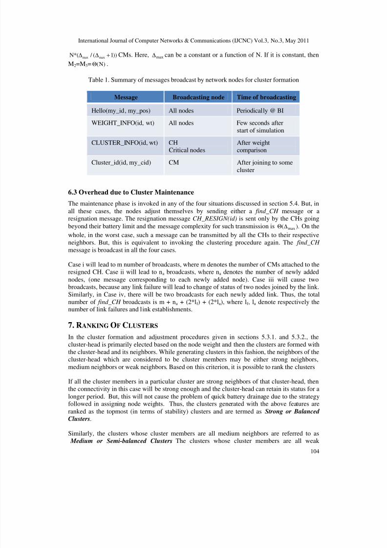
Table 1. Summary of messages broadcast by network nodes for cluster formation
Message Broadcasting node Time of broadcasting
Hello(my_id, my_pos) All nodes Periodically @ BI
WEIGHT_INFO(id, wt) All nodes Few seconds after
start of simulation
CLUSTER_INFO(id, wt) CHCritical nodes
After weightcomparison
Cluster_id(id, my_cid) CM After joining to some
cluster
6.3 Overhead due to Cluster Maintenance
The maintenance phase is invoked in any of the four situations discussed in section 5.4. But, in
all these cases, the nodes adjust themselves by sending either a find_CH message or aresignation message. The resignation message CH_RESIGN(id) is sent only by the CHs going
beyond their battery limit and the message complexity for such transmission is ).( max∆Θ On the
whole, in the worst case, such a message can be transmitted by all the CHs to their respective
neighbors. But, this is equivalent to invoking the clustering procedure again. The find_CH
message is broadcast in all the four cases.
Case i will lead to m number of broadcasts, where m denotes the number of CMs attached to theresigned CH. Case ii will lead to na broadcasts, where na denotes the number of newly added
nodes, (one message corresponding to each newly added node). Case iii will cause two
broadcasts, because any link failure will lead to change of status of two nodes joined by the link.Similarly, in Case iv, there will be two broadcasts for each newly added link. Thus, the total
number of find_CH broadcasts is m + na + (2*lf ) + (2*la), where lf , la denote respectively thenumber of link failures and link establishments.
7. RANKING OF CLUSTERS
In the cluster formation and adjustment procedures given in sections 5.3.1. and 5.3.2., thecluster-head is primarily elected based on the node weight and then the clusters are formed with
the cluster-head and its neighbors. While generating clusters in this fashion, the neighbors of thecluster-head which are considered to be cluster members may be either strong neighbors,
medium neighbors or weak neighbors. Based on this criterion, it is possible to rank the clusters
If all the cluster members in a particular cluster are strong neighbors of that cluster-head, thenthe connectivity in this case will be strong enough and the cluster-head can retain its status for a
longer period. But, this will not cause the problem of quick battery drainage due to the strategyfollowed in assigning node weights. Thus, the clusters generated with the above features are
ranked as the topmost (in terms of stability) clusters and are termed as Strong or Balanced
Clusters.
Similarly, the clusters whose cluster members are all medium neighbors are referred to as Medium or Semi-balanced Clusters. The clusters whose cluster members are all weak
8/6/2019 Quality of Service Provisioning in MANET Using a Cross-Layer Approach for Routing
International Journal of Computer Networks & Communications (IJCNC) Vol.3, No.3, May 2011
105
neighbors are ranked as Weak or Unbalanced Clusters. There may be cases in which thecluster members are combinations of strong, medium and weak neighbors and such clusters aretermed as Intermediate Clusters. In due course, because of the dynamic nature of our network,
these Clusters can change into any of the above mentioned three types of clusters.
8. SIMULATION STUDY 8.1. Simulation Parameters
The validity of the theoretical analysis and the performance evaluation of SD_DWCA are
obtained via simulation of the algorithm using NS-2 with CMU wireless extension. Wesimulate a system of N nodes whose positions are randomly generated on a terrain of size XxY
with a restricted diameter using the scenario generator available in NS-2 with the inputparameters as listed in Table 2.
Table 2. Simulation Parameters for SD_DWCA
Parameter Meaning Value(s) used in Simulation
N Number of nodes 50,75,100,150,200
XxY Terrain size/Network deploymentarea
750x750
Max SpeedMaximum Speed with which the
nodes move in random directions
[0, Vmax], where Vmax = 10, 20,
30, 40, 50m/s
Tx Range Transmission range 100, 150, 200, 250, 300 (metres)
PT Pause Time 30s
Mobility ModelThe mobility model based on which
the nodes move in random directions
Random Way Point mobility
model
IE Initial Energy 100 Joules
Mac Type Type of MAC layer 802.11
Traffic
Type of application used in data
transmission between sources &destinations
CBR
Packet size_ Size of packet transmitted 1000bytes
Interval_Time interval between transmissionof packets
0.005s
T Simulation time 500s
8.2. Performance Metrics
To measure the performance of our algorithm, the following metrics are considered.
1. Average number of Clusters – The number of clusters generated on an average duringthe simulation run time of our algorithm
2. Rate of re-affiliations – The number of cluster members which change their affiliations
(Event of link breakage with the current cluster-head and link establishment with a newcluster-head due to mobility) per unit time.
8/6/2019 Quality of Service Provisioning in MANET Using a Cross-Layer Approach for Routing
International Journal of Computer Networks & Communications (IJCNC) Vol.3, No.3, May 2011
106
3. Average end-to-end throughput – The number of bytes successfully transmitted per unittime. i.e., the ratio of the transmitted packet size to the average end-to-end delay
4. Overhead due to cluster formation – The number of control packets required to be
transmitted for successful formation of clusters
5. Overhead due to cluster Maintenace – The number of control packets to be transmitted
to update the change in cluster structure due to mobility of nodes and arrival of newnodes
8.2.1. Average number of clusters
The following graphs are plotted to analyze of impact of transmission range and mobility on theaverage number of clusters for a varied number of nodes in the network. Figure 2 gives the
impact of transmission range on the average number of clusters. The graphs are plotted forTransmission range varying from 100-300 (in steps of 50) for varied number of nodes ranging
from 50 to 200, keeping maximum displacement fixed.
Figure 2. Impact of Transmission range on average no. of clusters
It can be seen from the above graphs that the average number of clusters generated decreases as
the transmission range increases, which is a natural phenomena. This is due to the well-knownfact that as the communication range of each node increases, more number of nodes can be
grouped into a single cluster thereby reducing the number of clusters generated.
Again, to analyze the impact of mobility, the graphs are plotted for Max speed varying from 10-50m/s (in steps of 10) for varied number of nodes ranging from 50 to 200, keeping transmission
range fixed. This analysis is also performed to see the validity of the algorithm for high-speednetworks. It can be witnessed from the graphs shown in Figure 3(a), (b), (c) & (d) that though
the number of clusters generated increases with increase in velocity/maximum speed, the rate of
increase is negligibly small. In some cases (Figure 3(b), (c)), the number of clusters obtained
remains almost constant with increase in velocity. This guarantees that the algorithm can beused to cluster high-speed networks.
8/6/2019 Quality of Service Provisioning in MANET Using a Cross-Layer Approach for Routing
International Journal of Computer Networks & Communications (IJCNC) Vol.3, No.3, May 2011
107
Figure 3(a) (Tx range =100m) Figure 3(b) (Tx range =150m)
Figure 3(c) (Tx range =250m) Figure 3(d) (Tx range =300m)
Figure 3. Impact of Mobility on average no. of clusters
8.2.2. Rate of re-affiliations
The following graphs are plotted to analyze the stability of the cluster structures developed.From the graphs shown in Figure 4, it can be inferred that the rate of re-affiliation increases as
International Journal of Computer Networks & Communications (IJCNC) Vol.3, No.3, May 2011
108
the number of nodes increases and reaches a peak value (which is nearly 0.02 much lesser thanunity) and after that decreases to almost 0.005. The same behaviour is analyzed even withincrease in maximum speed with which the nodes are allowed to move. This shows that the
proposed algorithm generates highly stable clusters even for networks with high mobility. This
is guaranteed by the choice of the weight parameters.
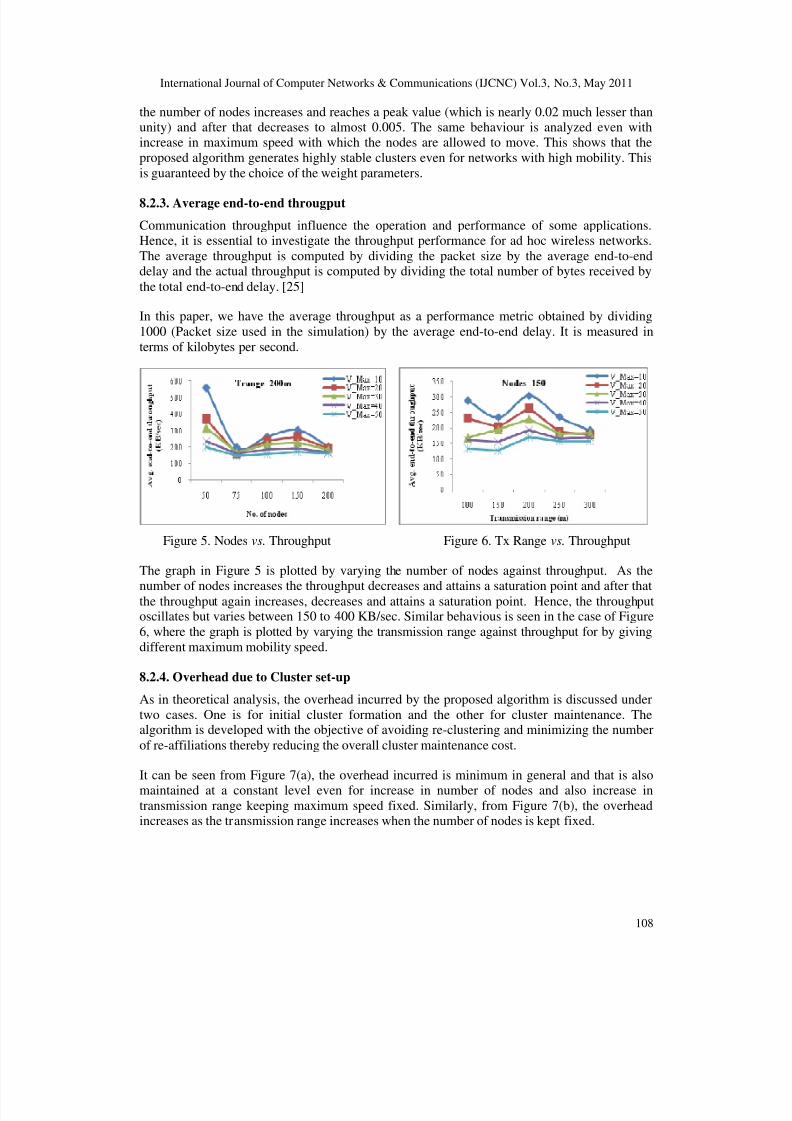
8.2.3. Average end-to-end througput
Communication throughput influence the operation and performance of some applications.Hence, it is essential to investigate the throughput performance for ad hoc wireless networks.
The average throughput is computed by dividing the packet size by the average end-to-enddelay and the actual throughput is computed by dividing the total number of bytes received by
the total end-to-end delay. [25]
In this paper, we have the average throughput as a performance metric obtained by dividing
1000 (Packet size used in the simulation) by the average end-to-end delay. It is measured in
terms of kilobytes per second.
Figure 5. Nodes vs. Throughput Figure 6. Tx Range vs. Throughput
The graph in Figure 5 is plotted by varying the number of nodes against throughput. As the
number of nodes increases the throughput decreases and attains a saturation point and after thatthe throughput again increases, decreases and attains a saturation point. Hence, the throughputoscillates but varies between 150 to 400 KB/sec. Similar behavious is seen in the case of Figure
6, where the graph is plotted by varying the transmission range against throughput for by giving
different maximum mobility speed.
8.2.4. Overhead due to Cluster set-up
As in theoretical analysis, the overhead incurred by the proposed algorithm is discussed under
two cases. One is for initial cluster formation and the other for cluster maintenance. Thealgorithm is developed with the objective of avoiding re-clustering and minimizing the number
of re-affiliations thereby reducing the overall cluster maintenance cost.
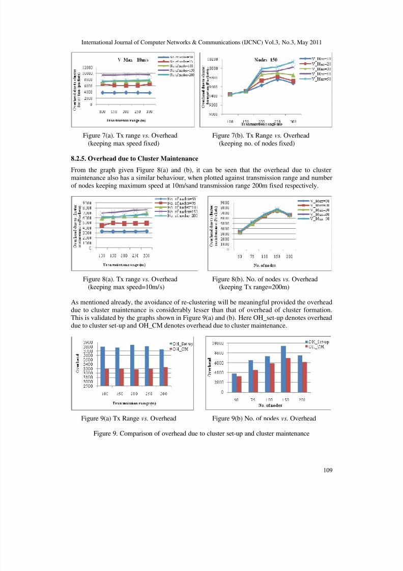
It can be seen from Figure 7(a), the overhead incurred is minimum in general and that is also
maintained at a constant level even for increase in number of nodes and also increase intransmission range keeping maximum speed fixed. Similarly, from Figure 7(b), the overheadincreases as the transmission range increases when the number of nodes is kept fixed.
8/6/2019 Quality of Service Provisioning in MANET Using a Cross-Layer Approach for Routing
International Journal of Computer Networks & Communications (IJCNC) Vol.3, No.3, May 2011
109
Figure 7(a). Tx range vs. Overhead Figure 7(b). Tx Range vs. Overhead
(keeping max speed fixed) (keeping no. of nodes fixed)
8.2.5. Overhead due to Cluster Maintenance
From the graph given Figure 8(a) and (b), it can be seen that the overhead due to cluster
maintenance also has a similar behaviour, when plotted against transmission range and number
of nodes keeping maximum speed at 10m/sand transmission range 200m fixed respectively.
Figure 8(a). Tx range vs. Overhead Figure 8(b). No. of nodes vs. Overhead
(keeping max speed=10m/s) (keeping Tx range=200m)
As mentioned already, the avoidance of re-clustering will be meaningful provided the overheaddue to cluster maintenance is considerably lesser than that of overhead of cluster formation.
This is validated by the graphs shown in Figure 9(a) and (b). Here OH_set-up denotes overheaddue to cluster set-up and OH_CM denotes overhead due to cluster maintenance.
Figure 9(a) Tx Range vs. Overhead Figure 9(b) No. of nodes vs. Overhead
Figure 9. Comparison of overhead due to cluster set-up and cluster maintenance
8/6/2019 Quality of Service Provisioning in MANET Using a Cross-Layer Approach for Routing
International Journal of Computer Networks & Communications (IJCNC) Vol.3, No.3, May 2011
110
9. CONCLUSION
In the networks considered here, we allow mobility of the nodes in all possible directions.Hence, a node which is a weak neighbor at an instant may become a medium or strong neighbor
at a later instant. Similarly, a medium neighbor may either become a strong or a weak neighborand this leads to re-election of CHs. But, this situation can be avoided as much as possible by
the choice of our mobility metric. Thus, the algorithm is reliable even for high speed networks.It is evident from the adjustment procedures given in section 5.3.2 that to reduce the number of
critical nodes, we adopt re-affiliation rather than re-clustering and this greatly reduces the cost
of cluster maintenance. Thus, the proposed algorithm is efficient in terms of both execution andmaintenance. The experimental results obtained support the theoretical observations.
REFERENCES
[1] A.A. Abbasi, M.I. Buhari, M.A. Badhusha, “Clustering Heuristics in Wireless Networks: A
survey”, Proc. 20th
European Conference on Modelling and Simulation (2006).
[2] R. Aoudjit, M. Lalam, A.M. Zoughi, M. Belkadi, M. Daoui, “Load Balancing: An Approach Based
on Clustering in Ad Hoc Networks”, J. Computing and Information Technology, vol. 17, No. 2, pp.
177-184 (2009)
[3] D.J. Baker, A. Epremides, “A distributed algorithm for organizing mobile radio telecommunicationnetworks”, Proc. 2nd International conference on Distributed Computer systems, pp. 476-483.
IEEE Press, France (1981)
[4] D.J. Baker, A. Epremides, “The architectural organization of a mobile radio networks via a
distributed algorithm”, IEEE Transactions on Communications, vol. COM-29, No. 11, pp. 1694-
1701 (1981)
[5] P. Basu, N. Khan, T.D.C. Little, “A mobility based metric for clustering in mobile ad hoc
networks”, Proc. of IEEE ICDCS, pp. 413-418. Phoenix, Arizona, USA (2001)
[6] C. Bettstetter, Stefan Konig “On the message and time complexity of a distributed mobility-
adaptive clustering algorithm in wireless ad hoc networks”, Proc. 4th
European wireless, pp. 128-
134. Florence, Italy (2002)
[7] M. Chatterjee, S.K. Das, D. Turgut, “A Weight Based Distributed Clustering Algorithm for
MANET, HiPC 2000”, LNCS, pp. 511-521. Springer-Verlag, Heidelberg (2000)[8] M. Chatterjee, S.K. Das, D. Turgut, “WCA: A Weighted Clustering Algorithm for Mobile Ad Hoc
Networks”, Cluster Computing, vol. 5, pp. 193-204. Kluwer Academic Publishers, The
Netherlands (2002)
[9] W. Choi, M. Woo, “A Distributed Weighted Clustering Algorithm for Mobile Ad hoc Networks”,
Proc. of AICT/ICIW 2006. IEEE (2006)
[10] S.J. Francis, E.B. Rajsingh, “Performance Analysis of Clustering Protocols in Mobile Ad Hoc
Networks”, J. Computer Science, vol. 4, No. 3, pp. 192-204 (2008)
[11] M. Gerla, J.T.C. Tsai, “Multi-cluster, mobile, multimedia radio network”, Wireless Networks, vol.
1, No. 3, pp. 255-265 (1995)
[12] R.C. Hincapié, B.A. Correa, L. Ospina, “Survey on clustering Techniques for mobile ad hoc
networks”, IEEE (2006)
[13] Inn Inn ER, K.G.S. Winston “Performance Analysis of Mobility-based d-Hop (MobDHop)
Clustering Algorithm for Mobile Ad Hoc Networks”, Computer Networks, vol. 50, pp. 3375-3339
(2006)
[14] Inn Inn ER, K.G.S. Winston “Clustering overhead and convergence time analysis of the mobility-
based multi-hop clustering algorithm for mobile ad hoc networks”, Proc. 11th
Int. conference on
parallel and distributed systems (ICPADS’ 05), pp. 1144-1155 (2005)[15] T. Johansson, L. Carr-Matyčková, “On Clustering in Ad Hoc Networks”, Proc. Vehicular Tech.
Conf. Fall, Swedish National Computer Networking Workshop (2003)
[16] A.B. McDonald, T.F. Znathi, “A Mobility-based framework for adaptive clustering in wireless ad
hoc networks”, IEEE Journal on Selected Areas in Communications, vol. 17, No. 8, pp. 1466-1487
(1999)
[17] A.K. Parekh, “Selecting routers in ad-hoc wireless networks”, Proc. SB/IEEE International
Telecommunications Symposium (1994)
[18] S. Gajurel “Multi-Criteria Clustering (2006)
8/6/2019 Quality of Service Provisioning in MANET Using a Cross-Layer Approach for Routing
International Journal of Computer Networks & Communications (IJCNC) Vol.3, No.3, May 2011
111
[19] P.R. Sheu, C.W. Wang, “A Stable Clustering Algorithm based on Battery Power for Mobile Ad
Hoc Networks”, Tamkang Journal of Science and Engineering, vol. 9, No. 3, pp. 233-242 (2006)
[20] Z. Xing, L. Gruenwald, K.K. Phang, “A Robust Clustering Algorithm for Mobile Ad Hoc
Networks”, Handbook of Research on Next Generation Networks and Ubiquitous Computing,
December 2008
[21] J.Y. Yu, P.H.J. Chong, “A Survey of Clustering Schemes for Mobile Ad Hoc Networks”, IEEE
Communications Surveys and Tutorials, First Quarter, vol. 7, No. 1, pp. 32-47 (2005)[22] W. Yang, G. Zhang, “A Weight-based clustering algorithm for mobile Ad hoc networks”, Proc. 3rd
Int. Conf. on wireless and mobile communications (2007)
[23] T.N. Janakiraman and A.S. Thilak, “A Distributed Mobility-Adaptive and Energy Driven
Clustering Algorithm for MANETs using strong degree”, Advances in Networks and
Communications, N. Meghanathan et al. (eds.), CCIS, Vol. 132, Part – II, pp. 645-655, Proc. of
CCSIT 2011, Springer, Heidelberg, 2011.
[24] T.N. Janakiraman and A.S. Thilak, “A Weight based double star embedded clustering of
homogeneous mobile ad hoc networks using graph theory”, Advances in Networks and
Communications, N. Meghanathan et al. (eds.), CCIS, Vol. 132, Part – II, pp. 329-339, Proc. of
CCSIT 2011, Springer, Heidelberg, 2011.
[25] C.K. Toh, “Ad Hoc Mobile Wireless Networks Protocols and Systems”, Pearson Education, Inc.and Dorling Kindersley Publishing, Inc., India, 2
ndedition, 2009.
Authors
T.N. Janakiraman is currently Associate Professor of Department of
Mathematics, National Institute of Technology, Tiruchirapalli, India. He
completed his undergraduate Studies at Madras University, India in 1980
and completed his Post graduation at National College, Trichy, India in
1983. He did his Ph.D. in Mathematics (Graph Theory and its applications)
at Madras University with a UGC sponsored research fellowship and
received his doctoral degree in the year 1991. He was a Postdoctoral
Research associate for 1 year (1993-1994) in Madras University under the
He has two sponsored research projects to his credit and published around
70 papers in refereed National/International journals. His research interests
include Pure Graph Theory, Applications of Graph Theory to Fault tolerant
networks, Central location problems, Clustering of wired & wireless ad hoc
networks, Clustering of cellular and flexible manufacturing models, Imageprocessing, Graph coding and Graph Algorithms.
A. Senthil Thilak is currently a research Scholar of Department of
Mathematics, National Institute of Technology, Tiruchirapalli, India. She
received her Master’s degree in Mathematics and Master of Philosophy in
Mathematics from Seethalakshmi Ramaswami College, Tiruchirapalli,
India. She has completed Post Graduate Diploma in Computer Applications
in Bharathidasan University, Tiruchirapalli, India. She has published three
papers in refereed National/International Journals. Her main research
interests include Pure Graph Theory, Algorithmic Graph Theory and
applications of graph theory to wireless ad hoc networks.


![EXPERIMENTAL EVALUATION OF LSPR ROUTING PROTOCOL€¦ · Demand-driven Routing Protocol for MANET[] AODV is a packet routing protocol designed for use in mobile ad hoc networks (MANET)](https://static.documents.pub/doc/80x56/5f526102bcd353229e7c4523/experimental-evaluation-of-lspr-routing-protocol-demand-driven-routing-protocol.jpg)

![Zone Based Ant Colony Routing in MANET[Report]](https://static.documents.pub/doc/80x56/5534d5f84a7959dc528b4cca/zone-based-ant-colony-routing-in-manetreport.jpg)


