25
Version: 1.0 QuantaPlex Series S41T-2U 2U 4-Node Server Featuring Latest Intel® Xeon Phi™ Technology User’s Guide

Version: 1.0
QuantaPlex SeriesS41T-2U
2U 4-Node Server FeaturingLatest Intel® Xeon Phi™ Technology
User’s Guide

I
Copyright
Copyright © 2016 Quanta Computer Inc. This publication, including all photographs, illus-trations and software, is protected under international copyright laws, with all rights reserved. Neither this guide, nor any of the material contained herein, may be reproduced without the express written consent of the manufacturer. All trademarks and logos are copyrights of their respective owners.
Version 1.0 / October 26, 2016
Disclaimer
The information in this document is subject to change without notice. The manufacturer makes no representations or warranties with respect to the contents hereof and specifi-cally disclaims any implied warranties of merchantability or fitness for any particular pur-pose. Furthermore, the manufacturer reserves the right to revise this publication and to make changes from time to time in the content hereof without obligation of the manufac-turer to notify any person of such revision or changes.
For the latest information and updates please see www.QCT.io
All the illustrations in this guide are for reference only and are subject to change without prior notice.
Intended Application Uses
This product was evaluated as Information Technology Equipment (ITE), which may be installed in offices, schools, computer rooms, and similar commercial type locations. The suitability of this product for other product categories and environments (such as medical, industrial, residential, alarm systems, and test equipment), other than an ITE application, may require further evaluation.

TABLE OF CONTENTS
II
TABLE OF CONTENTS
About the System
Introduction . . . . . . . . . . . . . . . . . . . . . . . . . . . . . . . . . . . . . . . . . . . . . . . . . . . . . . . . . . 1-1System Features. . . . . . . . . . . . . . . . . . . . . . . . . . . . . . . . . . . . . . . . . . . . . . . . . . 1-1
A Tour of the System . . . . . . . . . . . . . . . . . . . . . . . . . . . . . . . . . . . . . . . . . . . . . . . . . . 1-3System Overview . . . . . . . . . . . . . . . . . . . . . . . . . . . . . . . . . . . . . . . . . . . . . . . . . 1-3System Front View. . . . . . . . . . . . . . . . . . . . . . . . . . . . . . . . . . . . . . . . . . . . . . . . 1-4Front Control Panel and Status LED . . . . . . . . . . . . . . . . . . . . . . . . . . . . . . . 1-5Rear View . . . . . . . . . . . . . . . . . . . . . . . . . . . . . . . . . . . . . . . . . . . . . . . . . . . . . . . . 1-5Rear I/O Ports . . . . . . . . . . . . . . . . . . . . . . . . . . . . . . . . . . . . . . . . . . . . . . . . . . . . 1-6HDD Configuration . . . . . . . . . . . . . . . . . . . . . . . . . . . . . . . . . . . . . . . . . . . . . . . 1-7Power Sub-System . . . . . . . . . . . . . . . . . . . . . . . . . . . . . . . . . . . . . . . . . . . . . . . 1-7
PSU LED . . . . . . . . . . . . . . . . . . . . . . . . . . . . . . . . . . . . . . . . . . . . . . . . . . . . . . . 1-8Cooling Sub-System . . . . . . . . . . . . . . . . . . . . . . . . . . . . . . . . . . . . . . . . . . . . . . 1-8
Connectors
Mainboard Connectors . . . . . . . . . . . . . . . . . . . . . . . . . . . . . . . . . . . . . . . . . . . . . . . . 2-1Mainboard Overview . . . . . . . . . . . . . . . . . . . . . . . . . . . . . . . . . . . . . . . . . . . . . 2-1
Regulatory and Compliance Information

CONVENTIONS
III
ConventionsSeveral different typographic conventions are used throughout this manual. Refer to the following examples for common usage.
Bold type face denotes menu items, buttons and application names.
Italic type face denotes references to other sections, and the names of the folders, menus, programs, and files.
<Enter> type face denotes keyboard keys.
WARNING!Warning information appears before the text it references and should not be ignored as the content may prevent damage to the device.
CAUTION!CAUTIONS APPEAR BEFORE THE TEXT IT REFERENCES, SIMILAR TO NOTES AND WARNINGS. CAUTIONS, HOWEVER, APPEAR IN CAPITAL LETTERS AND CONTAIN VITAL HEALTH AND SAFETY INFORMATION.
Note:Highlights general or useful information and tips.
!
!

IV
Structure of this guide Chapter 1: About the System
“This section introduces the system, its different configuration(s) and the main features.”
Chapter 2: Connectors
“This section provides guidance information for the position and configuration of connectors.”
Chapter 3: Regulatory and Compliance Information
“This section provides regulatory and compliance information applicable to this system.”

About the SystemChapter 1
This section introduces the system, its different configuration(s) and the main features.

ABOUT THE SYSTEM INTRODUCTION
1.1 IntroductionThis manual is to provide the basic information for users.
System Features
The system comprises a 2U/30.5” long chassis using a standard SSI mainboard. Major features per sled include:
Chipset: Intel® C610 series
Processor: Intel® Xeon Phi™ Product Family x200 or Intel® Xeon Phi™ Product Family x200 with Integrated Fabric
PCIe slots:
(1) PCIe x16 Gen3 riser slot for low-profile card per node
(1) PCIe x16 Gen3 mezzanine slot for OCP mezzanine card per node
Memory: Up to six DIMM slots are available. DDR4 2133/2400 MT/s RDIMM and LRDIMM memory are supported.
Network*: (1) Dedicated GbE management port
*Visit www.qct.io for the latest Network support listings.
Note:The system supports: 1600W 200V-240V.
Table 1: 2U4N Specification
SPECIFICATION DESCRIPTION
Form factor (W x H x D) 2U chassis 444mm x 87.5mm x 790mm / 17.48" x 3.44" x 31.1"
Mainboard form factor (Wx L), half-width
165mm x 491mm / 6.5" x 19.35" Up to 4 indenpendent mainboard sleds
Processor (1) Intel® Xeon Phi™ Product Family x200 per node, up to 245W
(1) Intel® Xeon Phi™ Product Family x200 with Integrated Fabric per node, up to 260W
Chipset Intel® C610
Memory(6) DDR4 2133/2400 MT/s ECC RDIMM/LRDIMM slots with six channels per node, up to 384 GB
Storage(24) 2.5" hot-plug SATA HDD/SSD per system, (6) 2.5" hot-plug SATA HDD/SSD per node
HDD backplane 1 to 1
1-1

ABOUT THE SYSTEM SYSTEM FEATURES
Expansion slot
For Intel® Xeon Phi™ Product Family X200 SKU (1) PCIe x16 Gen3 riser slot for low-profile card per node (1) PCIe x16 Gen3 OCP mezzanine slot for OCP mezzanine card per nodeFor Intel® Xeon Phi™ Product Family X200 with Integrated Fabric SKU (1) PCIe x4 Gen3 riser slot for low-profile card per node
(1) OCP mezzanine slot with Intel® Omni-Path Architecture (OPA) per node
Internal storage
(1) 2280 M.2 slot0 for PCIe SSD (PCIe x4 Gen2), dual layout with SATA port 0 (1) 2280 M.2 slot1 for SATA SSD, dual layout with SATA port 1**This M.2 slot will not be available or removed from mainboard while 7-pin SATA port with 3-pin power connector installed to support SATA DOM.
Management port (1) Dedicated GbE RJ45 management port per node
Integrated graphics BMC
ASPEED AST2400 for dedicated management NIC port
Front I/O (1) USB 2.0 port per node
Rear I/O
(2) USB 3.0 ports per node (1) VGA per node (1) RS232 Serial port per node (1) GbE RJ45 management port per node
Power supply unit (2) 1600W high efficiency hot-plug redundant PSUs, 200-240Vac, 8A, 50/60Hz
Rating (per PSU inlet) (1) 200-240Vac, 8A, 50/60Hz
RoHS Yes
Intel node management support
Yes
TPM support TPM 2.0 with Serial Peripheral Interface (SPI) interface
Fan (4) dual-rotor fan modules support 7+1 redundant mode
System management IPMI v2.0 Compliant, on board "KVM over IP" support
Operating environment
Operating temperature: 5°C to 35°C (41°F to 95°F) Non-operating temperature: -40°C to 65°C (-40°F to 149°F) Operating relative humidity: 20% to 85%RH. Non-operating relative humidity: 40% to 90%RH
Table 1: 2U4N Specification (Continued)
SPECIFICATION DESCRIPTION
1-2

ABOUT THE SYSTEM A TOUR OF THE SYSTEM
1.2 A Tour of the System
System Overview
The system is available in 24 x 2.5” SATA HDD/SSD model. The following illustrations describe the major components of the model.
Figure 1-1. System Component Overview
Table 2: System Component Overview
NO. ITEM DESCRIPTION
1Power supply unit (PSU)
Two 1600W high efficiency redundant PSU, 200-240Vac, 8A, 50/60Hz
2 MB sled Hot-swap mainboard sleds (x4)
3 Fan assembly cover Open to service fan modules
4 Chassis2U System chassis444mm/17.48"(W)x 87.5mm/3.44"(H)x 790mm/31.1"(D)
5 Server handle
Two server handles used for pulling the system out of the rack
CAUTION!THE HANDLES ARE DESIGNED FOR THE EXTENSION OF THE SYSTEM FROM THE RACK. THE HANDLES ARE NOT DESIGNED TO CARRY THE WEIGHT OF THE SYSTEM. DO NOT USE THE HANDLES TO MOVE OR LIFT THE SYSTEM.
6 Front control panelsFront control panels 1/2 (left) and 3/4 (right). See Front Control Panel and Status LED on page 1-5 for further information
7 2.5” HDD bay 2.5” hard disk drive (HDD) modules (x24)
8 Neck-top cover Remove to service HDD backplane.
❶
❷
❸
❹
❺
❽
❾
❿
⓫
❼
❻
❻
1-3
ABOUT THE SYSTEM SYSTEM FRONT VIEW
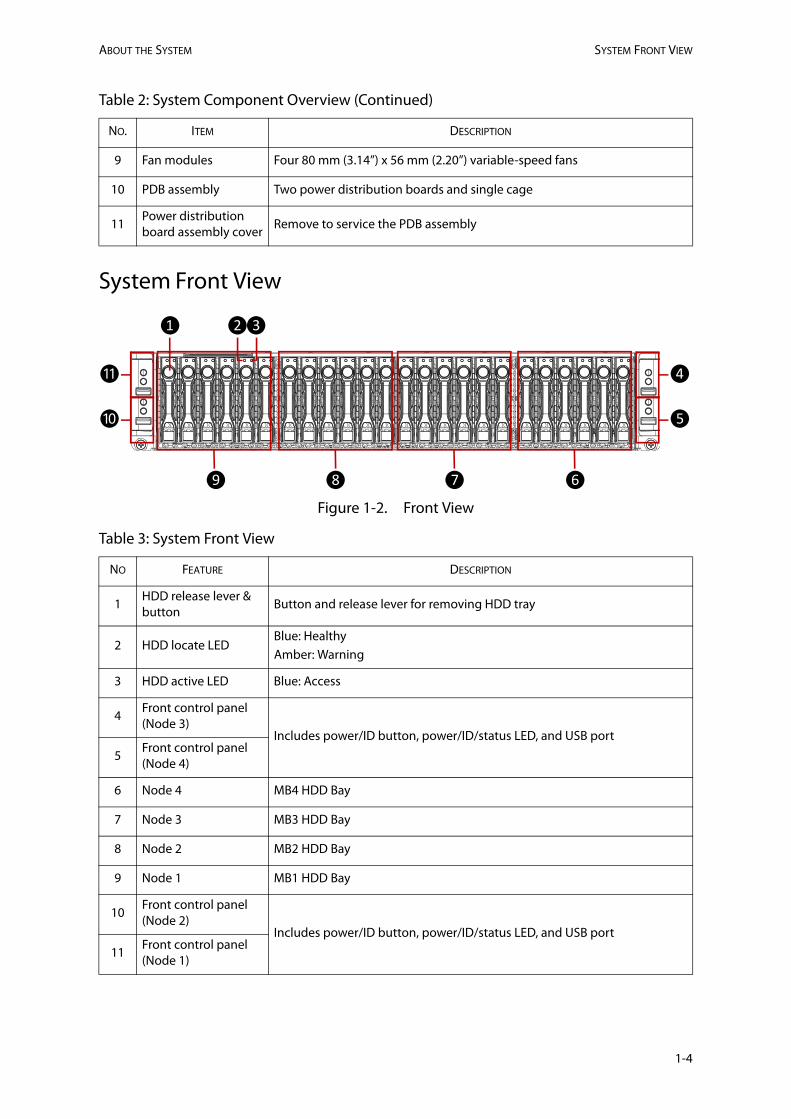
System Front View
Figure 1-2. Front View
9 Fan modules Four 80 mm (3.14”) x 56 mm (2.20”) variable-speed fans
10 PDB assembly Two power distribution boards and single cage
11Power distribution board assembly cover
Remove to service the PDB assembly
Table 3: System Front View
NO FEATURE DESCRIPTION
1HDD release lever & button
Button and release lever for removing HDD tray
2 HDD locate LEDBlue: HealthyAmber: Warning
3 HDD active LED Blue: Access
4Front control panel (Node 3)
Includes power/ID button, power/ID/status LED, and USB port
5Front control panel (Node 4)
6 Node 4 MB4 HDD Bay
7 Node 3 MB3 HDD Bay
8 Node 2 MB2 HDD Bay
9 Node 1 MB1 HDD Bay
10Front control panel (Node 2)
Includes power/ID button, power/ID/status LED, and USB port
11Front control panel (Node 1)
Table 2: System Component Overview (Continued)
NO. ITEM DESCRIPTION
❾
❶ ❷
❽ ❼ ❻
⓫
❿
❹
❺
❸
1-4

ABOUT THE SYSTEM FRONT CONTROL PANEL AND STATUS LED
Front Control Panel and Status LED
Figure 1-3. Front Control Panel
Rear View
The system rear consists of four mainboard sleds and two power supply units. Dummy modules are installed to maintain proper airflow in the event that mainboard slots are not fully populated.
Figure 1-4. System Rear View
Table 4: Front Control Panel
NO FEATURE DESCRIPTION
1Power button with LED
Blue on: System power onOff: System power offAmber blinking: DC off and faultAmber and blue blinking: DC on and fault
2 Status LED Amber blinking: System failure
3 ID button with LEDBlue blinking: ID indicatorOff: No indicator1: MB1 (2: MB2, 3: MB3, 4: MB4)
4 USB 2.0 port USB 2.0 port
❶❸❹
❷
1-5

ABOUT THE SYSTEM REAR I/O PORTS
Rear I/O Ports
Figure 1-5. Rear I/O Ports
Table 5: Rear I/O Ports
NO FEATURE DESCRIPTION
1 USB ports Dual 3.0 USB ports. Connect to USB device.
2 Serial port Standard DB9 serial port. Connect to serial device.
3 VGA portStandard VGA compatible, 15-pin connector supporting up to 1920 x 120032bpp@60Hz resolution. Connect to display device.
4 Management port Dedicated BMC LAN port (RJ45) for remote control / management.
5 Mainboard ID LEDOff: no identificationBlue (blinking): ID indicator
6Power button with Power and Status LED
Press and hold the power button more than four seconds to turn off the motherboard. Power LED
Off: power offGreen On: power on
Status LEDOff: no eventAmber (blinking): Critical failure/Non-critical failure
Note:The USB connector must be:
No bigger than 17mm/ 0.67" (W) x 8 mm / 0.31" (H) to avoid interference with the other ports.
Note:The temperature through the ventilation holes was high. Make sure to use a cable rated to withstand 75 degrees Celsius or higher.
❹❶ ❷ ❸ ❺❻
1-6

ABOUT THE SYSTEM HDD CONFIGURATION
HDD Configuration
Within the HDD array, the HDD enumeration is as follows:
Figure 1-6. HDD Configuration
Power Sub-System
Figure 1-7. PSU to Mainboard Sled Description
A system has two modular Power Supply Units (PSU). Both PSUs are directly connected to the Power Distribution Boards (PDBs), the HDD backplane, and middle plane allowing each PSU to individually provide power for all mainboards (MB1 to MB4).
The power supply units supported: 2 x 1600W redundant PSU @ 200V-240Vac, 8A, 50/60Hz.
WARNING!Mainboard combinations other than the system are not supported.
MB2BOTTOM (PSU2)MB4
MB1TOP (PSU1)MB3
!
1-7

ABOUT THE SYSTEM COOLING SUB-SYSTEM
PSU LED
Figure 1-8. PSU LED
Cooling Sub-System
Fans may spin for some time after the system has been powered off. Allow time for the fans to stop rotating before handling system components.
Figure 1-9. Cooling Sub System
Table 6: PSU LED Description
NO FEATURE STATUS DESCRIPTION
1 PSU LED
Green Normal operation
Amber: blinking Power off, fault
Green: blinking Power on, standby mode
❶
Fan 3
System Rear
Fan 2
Fan 1
Fan 0
1-8

ConnectorsChapter 2
This section provides guidance information for the position and configuration of con-nectors.

CONNECTORS AND JUMPERS MAINBOARD CONNECTORS
2-1
2.1 Mainboard Connectors
Mainboard Overview
Figure 2-1. Mainboard Connectors
C
c
B
b
A
a
FED
d
f
e
g
Mini-SAS HD: (a/b> SAS/SATA, c/d> PCIe HD; 4~7/0~3), (e: sSATA 0~3), (f: SATA 2~5), (g: PCIe x4)Socket PDDR4 288 pinSATA port 1 (for SATA DOM, dual layout /w #14 M.2)3-pin SATA DOM power connectorTPM headerPCIe Gen3 x16 slotGbE RJ45 Management portVGA Port DB15COM Port DB9USB 3.0 (x2)*Lithium battery holderM.2 connector (for SATA SSD, dual layout /w #5 SATA port 1)M.2 connector (for PCIe SSD, dual layout /w SATA port 0)CD sideband (Xeon® Phi™ x200/w Integrated Fabric only)OCP mezzanine connector x8+x8

Regulatory and Compliance InformationChapter 3
This section provides regulatory and compliance information applicable to this system.