Quantification of Diesel Engine Vibration Using Cylinder Deactivation for Exhaust Temperature Management and Recipe for Implementation in Commercial VehiclesAkibi Archer and James McCarthy Jr Eaton Corporation
Citation: Archer, A. and McCarthy Jr, J., “Quantification of Diesel Engine Vibration Using Cylinder Deactivation for Exhaust Temperature Management and Recipe for Implementation in Commercial Vehicles,” SAE Technical Paper 2018-01-1284, 2018, doi:10.4271/2018-01-1284.
Abstract
Commercial vehicles require continual improvements in order to meet fuel emission standards, improve diesel aftertreatment system performance and
optimize vehicle fuel economy. Aftertreatment systems, used to remove engine NOx, are temperature dependent. Variable valve actuation in the form of cylinder deactivation (CDA) has been shown to manage exhaust temperatures to the after-treatment system during low load operation (i.e., under 3-4 bar BMEP). During cylinder deactivation mode, a diesel engine can have higher vibration levels when compared to normal six cylinder operation. The viability of CDA needs to be implemented in a way to manage noise, vibration and harshness (NVH) within acceptable ranges for today’s commercial vehicles and drivelines. A heavy duty diesel engine (inline 6 cylinder) was instrumented to collect
vibration data in a dynamometer test cell. Three degrees of linear vibration and one degree of rotational vibration were measured using accelerometers and rotational speed sensors. Historical data analysis showed that the remaining two rota-tional degrees of freedom were insignificant when considering driveline vibration. The engine was tested using a combination of deactivating two, three and four cylinders (of the six) up to engine loads of approximately 4 bar BMEP in order to quantify system vibration and resonance frequencies. These results were compared to driveline NVH standards to determine the modes of operation that were acceptable over the engine speed and load operating range. A variable CDA implantation strategy for operating the engine over transient engine opera-tion is recommended for this dynamometer operation. Additionally, a theory is provided for operating cylinder deac-tivation in a commercial diesel vehicle.
Introduction
There are increasing pressures to improve exhaust emis-sions and fuel economy for commercial vehicles, agri-cultural equipment and passenger cars. This paper
focuses on diesel technology applied to the heavy duty market while the results are applicable to the medium duty market.
Passenger car emissions in the United States have been mandated to improve both fuel economy and CO2 reductions. The mandates have increased the average fuel economy for passenger car and light trucks from 27.5 miles per gallon equiva-lent (mpge) in 2008 to 35.5 mpge in 2016 [1]. The Environmental Protection Agency (EPA) and the National Highway Transportation and Safety Administration extended the improvement of fuel economy and greenhouse gases for passenger vehicle models in 2017 through 2025 [2]. These actions move the average required fleet wide fuel economy in 2025 in the range of 55.3 to 56.2 mpge for passenger cars, and 39.3 to 40.3 mpge for light trucks, resulting in a combined 48.7 to 49.7 mpge [2]. Variable valve actuation (VVA) including variable valve lift and early intake valve closing can be used in improve fuel economy on the order of 3-4% [3, 4, 5]. Cylinder deactivation
(CDA) is another type of VVA that has shown fuel economy improvement ranging from 2-12% [6, 7, 8, 9, 10, 11, 12, 13, 14] while typical gains are on the order of 5-6% [15, 16, 17, 18, 19].
There is a growing demand for improved fuel economy while reducing tailpipe emissions which is driving development of new engine and aftertreatment technologies. Aftertreatment systems are efficient for removing NOx as the exhaust and catalyst temperatures reach 250 °C while these systems are less efficient at lower temperatures. Exhaust thermal management is a key technology area for improving aftertreatment NOx effi-ciency while maintaining or improving engine fuel economy at the same time. One VVA method to increase aftertreatment temperature is to use early exhaust valve opening (EEVO). EEVO test results on a medium duty diesel engine showed an increase in exhaust temperature on the order of 30 to 80 °C with an associated fuel consumption increase of 15 to 23% [20, 21].
Cylinder deactivation is another VVA means to increase exhaust temperature at low load operation while improving fuel economy at the same time. Medium duty diesel results showed that CDA can be used to increase exhaust temperature by 100 °C while reducing fuel consumption at unloaded and
Downloaded from SAE International by Audra Ziegefuss, Tuesday, May 21, 2019
2 QUANTIFICATION OF DIESEL ENGINE VIBRATION USING CYLINDER DEACTIVATION
lightly loaded engine conditions [22, 23] depending on engine calibration. Additionally, VVA functions can be applied to the firing cylinders while other cylinders remain deactivated to yield even higher exhaust temperatures [24]. These VVA functions include variable valve lift, early intake valve closing, late intake valve closing and internal EGR. Later work showed that reactivating the cylinders remains first fire ready for accurate combustion supporting operating an engine in CDA mode for up to 20 minutes [25]. The torque requirements for vehicle acceleration starting in CDA mode and transitioning to normal six cylinder operation are met for starting in half engine CDA [26] along with one-third and two-thirds engine CDA [27]. Finally, exhaust temperatures have been shown to increase to active Diesel Particulate Filter (DPF) regeneration temperatures above 550 °C utilizing CDA at road-load cruise conditions without fuel dosing in the tailpipe [28].
One source of premature driveline component failures can be attributed to driveline torsional vibration problems. Driveline torsional vibration problems are also often a source of customer noise and vibration complaints in class 8 vehicles [29]. Driveline components have a resonance frequency that may align with the engine firing frequency at a point during the drive cycle as the engine speed changes. When the engine firing frequency aligns with a driveline resonance, the vibra-tion levels increase to a level that may damage driveline components. Vehicles using cylinder deactivation have a higher level of ignition force resulting in higher torque varia-tion. This higher torque variation with engines using cylinder deactivation can cause unacceptable levels of noise and vibra-tion performance [30]. Thus, engine vibration needs to be managed while in CDA mode. Active engine mounts using open and closed loop controls have been investigated as a solution to manage noise and vibration performance for engines using cylinder deactivation (Shin, 2007) [31]. This paper focuses on engine vibration of an inline, six cylinder, heavy duty diesel engine for CDA at low load. The benefits of operating CDA were quantified in terms of exhaust tempera-ture increase, fuel consumption, and friction from idle speeds of 800 rpm up to high speed conditions of 2100 rpm in previous works [32]. This work recommended operating half engine CDA below 3-4 bar BMEP over all engine speeds.
BackgroundThe four stroke, inline six cylinder diesel engine is commonly used in medium and heavy duty commercial vehicles. The engine used in this study has four valves per cylinder; each cylinder has a pair of intake valves and a pair of exhaust valves. Valve pairs are each connected to a common rocker arm and connecting bridge. The crankshaft contains six independent journals arranged in such a way as to produce a 1-5-3-6-2-4 firing order with combustion events occurring at 120° crank rotation intervals.
The firing frequency (Hz) can be calculated from the engine speed (rpm), by dividing the rpm by 60 since there are 60 rpm = 1 revolution per second, or 1 Hz. Thus, the firing frequency changes proportionally as the engine speed changes. Due to the design of the engine, each cylinder is fired only
once every two crank revolutions. This allows the calculation of the engine firing order based on the number of cylinders that are firing. Each cylinder firing once per two crank revolu-tions means that half of the cylinders are fired during one crank revolution. Therefore, for a 6 cylinder engine, the dominant order of vibration is 3rd order, and for an 8 cylinder engine, the dominant order of vibration is 4th order, and so on.
A six cylinder engine with appropriate CDA hardware can be operated with zero to six cylinders active. Different active cylinder counts may be advantageous depending on the engine operating state. Half engine CDA with three active cylinders has been shown to offer reduced fuel consumption and increased exhaust gas temperature at low engine loads and speeds [23, 24, 25, 26, 27]. Half engine CDA with even firing interval can be implemented on inline six cylinder diesel engines using two different schemas.
Figure 1a shows half engine operation with the front half of the engine inactive. Valves at cylinders 1, 2, and 3 remain stationary, and fuel injection only occurs in cylinders 4, 5, and 6. Combustion events occur in cylinders 4, 5, and 6 at 240° crank rotation intervals. Figure 1b shows half engine operation with the rear half of the engine inactive. Valves at cylinders 4, 5, and 6 remain stationary, and fuel injection only occurs in cylinders 1, 2, and 3. Combustion events occur in cylinders 1, 2, and 3 at 240° crank rotation intervals. During 3 cylinders firing (CF), the dominant order of torsional vibra-tion is 1.5th order (half of the number of active cylinders). The engine firing frequency can be calculated by using equation 1.
f rpm Oe d= * *1
60
min
sec (1)
Where Od is the dominant order and fe is the engine firing frequency. Therefore, at the limits of the speed range 600 and
FIGURE 1 Half engine CDA for inline six cylinder engine with (a) front half deactivated and (b) rear half deactivated.
1500 rpm the engine firing frequency limits in 3 CF mode are 15 and 37.5 Hz respectively.
Figure 2 shows four cylinders firing (CF) or two cylinder deactivated (CDA) with three variants. Figure 2a shows the middle cylinders (cylinder 3 and 4) deactivated while the other cylinders provide engine power (cylinders 1, 2, 5, and 6). Figure 2b shows the outside cylinders deactivated (cylinders 1 and 6) while the middle cylinders provide engine power (cylinder 2, 3, 4 and 5). Figure 2c shows cylinders 2 and 5 deactivated while the other cylinders provide engine power (cylinder 1, 3, 4 and 6). During 4 CF mode, theoretically due to the engine firing frequency, the dominant order of torsional vibration is 2nd order. Using equation 1, the engine firing frequency limits based on the engine speed range of 600 to 1500 rpm are 20 to 30 Hz respectively.
Figure 3 shows two CF or four CDA with three variants. Figure 3a shows the middle cylinders (cylinders 2, 3, 4 and 5) deactivated while the other cylinders provide engine power (cylinders 1 and 6). Figure 3b shows the outside cylinders deac-tivated (cylinders 1, 2, 5 and 6) while the middle cylinders provide engine power (cylinder 3 and 4). Figure 3c shows cylinders 2 and
5 providing engine power while the other cylinders are deacti-vated (cylinder 1, 3, 4 and 6). With 2 CF the dominant order of torsional vibration is 1st order. Using equation 1, calculating the engine firing frequency for the 600 to 1500 rpm speed range, results in the engine firing frequency range of 10-25 Hz.
The various methods of CDA are characterized from a vibrational perspective as to the vibrations transferred to the clutch of the transmission. All results in this paper were measured in a dynamometer test cell without a clutch or
FIGURE 2 Four cylinders firing for inline six cylinder engine with (a) middle deactivated (b) outside deactivated and (c) cylinders 2 and 5 deactivated.
transmission while the learnings could apply to a future vehicle test. The baseline vibration for this work is all six cylin-ders firing. Engine vibration is affected by cylinders firing as opposed to the cylinders deactivated. The results in this paper will refer to variants of two cylinders firing, three cylinders firing and four cylinders firing.
Engine Performance ResultsThe objective of this work is to determine the CDA variants that produce acceptable engine vibration in the areas where CDA is beneficial for aftertreatment temperature management and fuel consumption. These regions are generally below 3 bar brake mean effective pressure (BMEP). A variable CDA imple-mentation strategy (recipe) for managing torsional vibration below 3 bar BMEP is presented using a combination of the CDA variants across the engine speed and load map. The benefit of half engine CDA on a heavy duty diesel engine in terms of increase in turbine outlet temperature and fuel consumption are shown in Figures 4 and 5.
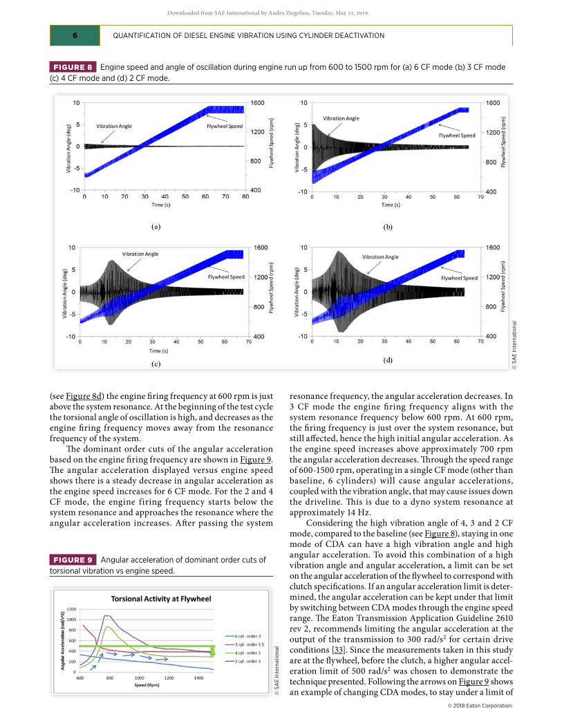
Figure 4 shows a contour of the increase in turbine outlet temperature using half engine CDA over the baseline of all six cylinders firing. Engine speeds were spanned from idle to typical engine cruise speeds. Engine loads were spanned to include 3 bar BMEP. Half engine CDA offers an increase in turbine outlet temperature from 50 to 120 C operating up to 3 bar BMEP. These increases in turbine outlet temperature can improve aftertreament NOx efficiency as these devices are temperature sensitive.
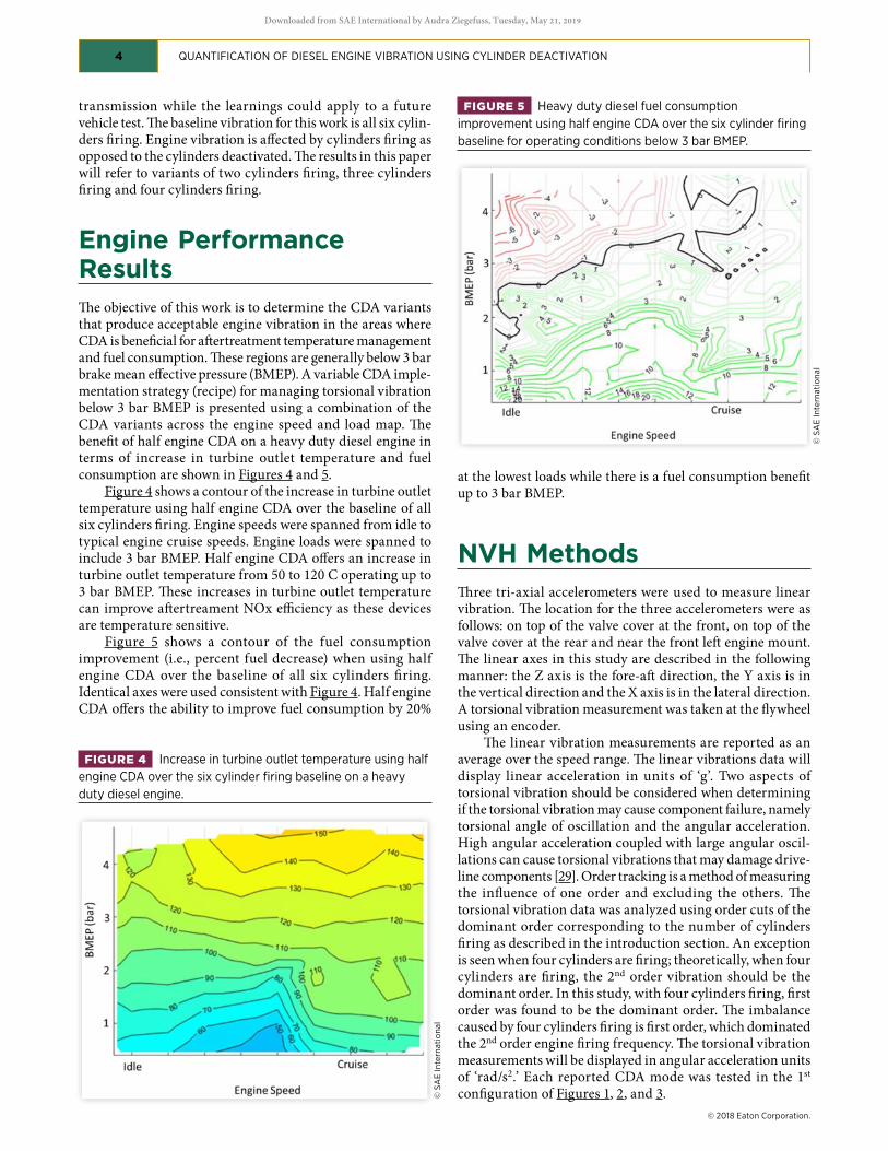
Figure 5 shows a contour of the fuel consumption improvement (i.e., percent fuel decrease) when using half engine CDA over the baseline of all six cylinders firing. Identical axes were used consistent with Figure 4. Half engine CDA offers the ability to improve fuel consumption by 20%
at the lowest loads while there is a fuel consumption benefit up to 3 bar BMEP.
NVH MethodsThree tri-axial accelerometers were used to measure linear vibration. The location for the three accelerometers were as follows: on top of the valve cover at the front, on top of the valve cover at the rear and near the front left engine mount. The linear axes in this study are described in the following manner: the Z axis is the fore-aft direction, the Y axis is in the vertical direction and the X axis is in the lateral direction. A torsional vibration measurement was taken at the flywheel using an encoder.
The linear vibration measurements are reported as an average over the speed range. The linear vibrations data will display linear acceleration in units of ‘g’. Two aspects of torsional vibration should be considered when determining if the torsional vibration may cause component failure, namely torsional angle of oscillation and the angular acceleration. High angular acceleration coupled with large angular oscil-lations can cause torsional vibrations that may damage drive-line components [29]. Order tracking is a method of measuring the influence of one order and excluding the others. The torsional vibration data was analyzed using order cuts of the dominant order corresponding to the number of cylinders firing as described in the introduction section. An exception is seen when four cylinders are firing; theoretically, when four cylinders are firing, the 2nd order vibration should be the dominant order. In this study, with four cylinders firing, first order was found to be the dominant order. The imbalance caused by four cylinders firing is first order, which dominated the 2nd order engine firing frequency. The torsional vibration measurements will be displayed in angular acceleration units of ‘rad/s2.’ Each reported CDA mode was tested in the 1st configuration of Figures 1, 2, and 3.
FIGURE 4 Increase in turbine outlet temperature using half engine CDA over the six cylinder firing baseline on a heavy duty diesel engine.
FIGURE 5 Heavy duty diesel fuel consumption improvement using half engine CDA over the six cylinder firing baseline for operating conditions below 3 bar BMEP.
Linear VibrationThe linear vibrations measured on the three points on the engine (top front, top rear and bottom front) are used to quantify the vibration levels that can be seen visually. These measurements were taken during a speed sweep from 600 rpm to 1500 rpm at 3.4 bar BMEP. Figure 7 shows linear vibration RMS measurements for 6, 4, 3, and 2 CF modes in the lateral (X), vertical (Y) and fore-aft (Z) direction for all three accel-erometer locations (see Figure 6). Figure 7a, showing the top front accelerometer, 2 CF mode has the highest RMS accelera-tion for all three directions. In the X direction, 6 CF has the lowest vibration level, while 4 CF mode is the lowest for the Y and Z directions. For the top rear accelerometer (closest to the flywheel), Figure 7b shows that 2 CF mode has the highest vibration level. Three CF mode is approximately equal to or lower than the 6 CF mode in the Y and Z directions, respec-tively. In the lateral direction the vibration at the top rear location on the valve cover, 6 CF had the lowest vibration level. Similarly to the top front and top rear accelerometer locations, the 2 CF mode had the highest vibration levels in all three directions for the bottom front accelerometer location (see Figure 7c). At the bottom front location, both the 4 and 3 CF modes showed lower vibration levels than the baseline of 6 CF.
The results of the linear vibration showed that 2 CF mode was consistently higher in linear vibration level when compared to the other modes at all accelerometer locations. In some positions, the 6 CF mode had the lowest vibration level and in other accelerometer positions and directions, the 4 and 3 CF mode had the lowest levels of vibration.
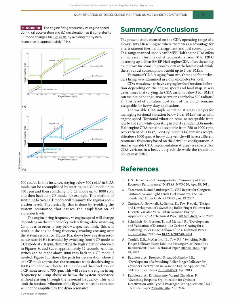
Torsional VibrationThe following results were obtained during a speed sweep from 600-1500 engine rpm at 2.92 bar BMEP. The torsional angle of oscillation changes as the engine speed changes. For 6 CF mode, the torsional angle of oscillation decreases as the engine rpm increases (see Figure 8a). This similar trend can be seen in 4, 3 and 2 CF mode as well. In 4 and 2 CF mode (see Figure 8b and Figure 8c), there is a system resonance
that is experienced as the engine speed sweeps at approxi-mately 12 seconds. This causes an increase in the torsional angle of oscillation. After passing through this resonance at approximately 12 seconds, the vibration angle decreases as the engine speed increases. Operating in 3 CF mode
FIGURE 7 Linear vibration RMS measurements for various number of cylinder firing at 3.4 bar BMEP at (a) top front, (b) top rear and (c) bottom front.
(see Figure 8d) the engine firing frequency at 600 rpm is just above the system resonance. At the beginning of the test cycle the torsional angle of oscillation is high, and decreases as the engine firing frequency moves away from the resonance frequency of the system.
The dominant order cuts of the angular acceleration based on the engine firing frequency are shown in Figure 9. The angular acceleration displayed versus engine speed shows there is a steady decrease in angular acceleration as the engine speed increases for 6 CF mode. For the 2 and 4 CF mode, the engine firing frequency starts below the system resonance and approaches the resonance where the angular acceleration increases. After passing the system
resonance frequency, the angular acceleration decreases. In 3 CF mode the engine firing frequency aligns with the system resonance frequency below 600 rpm. At 600 rpm, the firing frequency is just over the system resonance, but still affected, hence the high initial angular acceleration. As the engine speed increases above approximately 700 rpm the angular acceleration decreases. Through the speed range of 600-1500 rpm, operating in a single CF mode (other than baseline, 6 cylinders) will cause angular accelerations, coupled with the vibration angle, that may cause issues down the driveline. This is due to a dyno system resonance at approximately 14 Hz.
Considering the high vibration angle of 4, 3 and 2 CF mode, compared to the baseline (see Figure 8), staying in one mode of CDA can have a high vibration angle and high angular acceleration. To avoid this combination of a high vibration angle and angular acceleration, a limit can be set on the angular acceleration of the flywheel to correspond with clutch specifications. If an angular acceleration limit is deter-mined, the angular acceleration can be kept under that limit by switching between CDA modes through the engine speed range. The Eaton Transmission Application Guideline 2610 rev 2, recommends limiting the angular acceleration at the output of the transmission to 300 rad/s2 for certain drive conditions [33]. Since the measurements taken in this study are at the flywheel, before the clutch, a higher angular accel-eration limit of 500 rad/s2 was chosen to demonstrate the technique presented. Following the arrows on Figure 9 shows an example of changing CDA modes, to stay under a limit of
FIGURE 8 Engine speed and angle of oscillation during engine run up from 600 to 1500 rpm for (a) 6 CF mode (b) 3 CF mode (c) 4 CF mode and (d) 2 CF mode.
500 rad/s2. In this instance, staying below 500 rad/s2 in CDA mode can be accomplished by starting in 4 CF mode up to 750 rpm and then switching to 3 CF mode up to 1000 rpm and then back to 4 CF mode, for example. This method of switching between CF modes will minimize the angular accel-eration levels. Theoretically, this is done by avoiding the system resonance that causes the amplif ication of vibration levels.
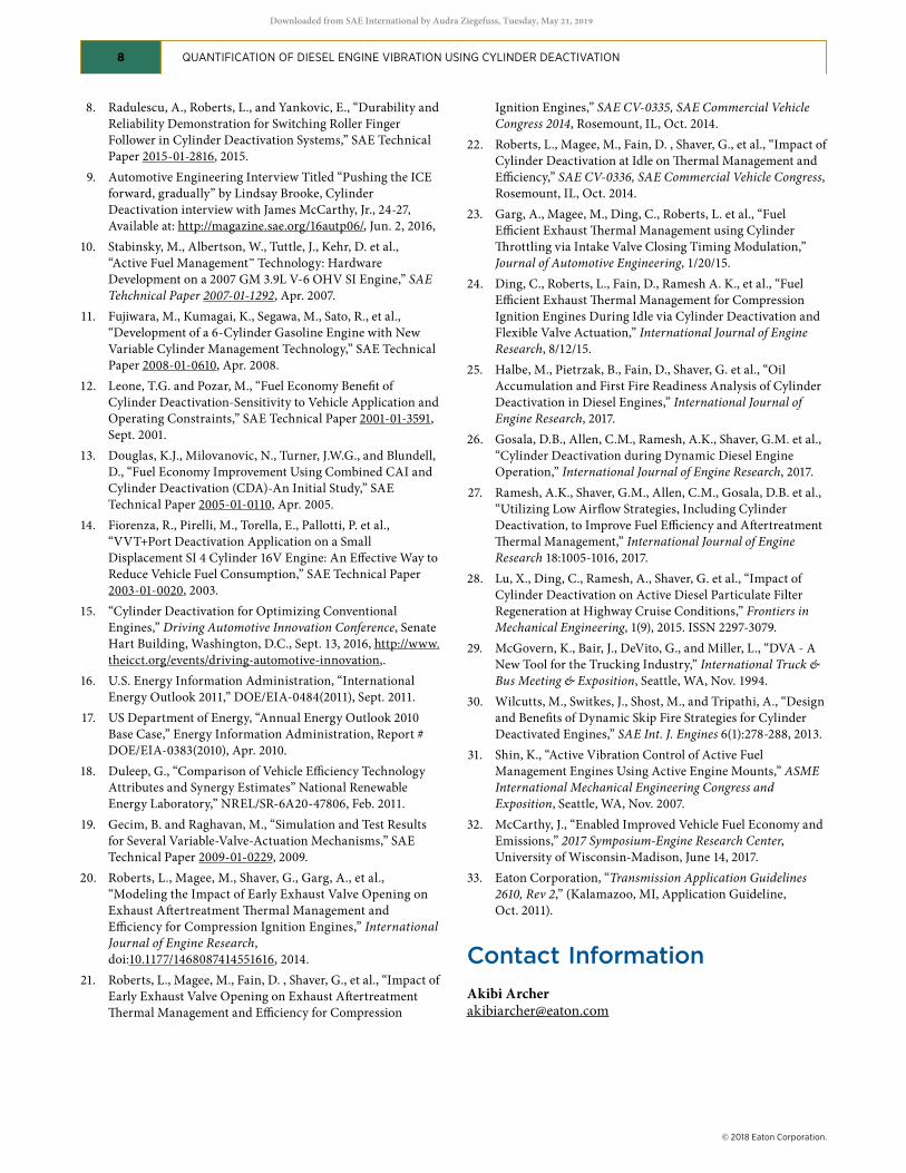
The engine firing frequency vs engine speed will change depending on the number of cylinders firing while switching CF modes in order to stay below a specified limit. This will result in the engine firing frequency avoiding crossing over the system resonance. Figure 10a, shows how a system reso-nance near 14 Hz is avoided by switching from 4 CF mode to 3 CF mode at 750 rpm, eliminating the high vibration observed in Figures 8c and 8d, at approximately 12 seconds. Another switch can be made above 1000 rpm back to 4 CF mode if needed. Figure 10b shows the path for deceleration where 2 or 4 CF mode approaches the resonance while decelerating to 1000 rpm, then switches to 3 CF mode and then back to 2 or 4 CF mode around 750 rpm. This will cause the engine firing frequency to jump above or below the system resonance without passing through the resonant frequency. This will limit the torsional vibration of the flywheel, since the vibration will not be amplified by the dyno resonance.
Summary/ConclusionsThe present study focused on the CDA operating range of a Heavy Duty Diesel Engine where there was an advantage for aftertreatment thermal management and fuel consumption. This range spanned up to 3 bar BMEP. Half engine CDA offers an increase in turbine outlet temperature from 50 to 120 C operating up to 3 bar BMEP. Half engine CDA offers the ability to improve fuel consumption by 20% at the lowest loads while there is a fuel consumption benefit up to 3 bar BMEP.
Variants of CDA ranging from two, three and four cylin-ders firing were examined in a dynamometer test cell.
CDA was shown to have varying levels of torsional vibra-tion depending on the engine speed and load map. It was determined that varying the CDA variants below 3 bar BMEP can maintain the angular acceleration at or below 500 radians/s2. This level of vibration upstream of the clutch remains acceptable for heavy duty applications.
The variable CDA implementation strategy (recipe) for managing torsional vibration below 3 bar BMEP varies with engine speed. Torsional vibration remains acceptable from idle to 750 rpm while operating in 2 or 4 cylinder CDA mode. Half engine CDA remains acceptable from 750 to 1000 rpm. Any variant of CDA (2, 3 or 4 cylinder CDA) remains accept-able above 1000 rpm. A heavy duty vehicle will have a different resonance frequency based on the driveline configuration. A similar variable CDA implementation strategy is expected for CDA variants in a heavy duty vehicle while the transition points may differ.
References 1. U.S. Department of Transportation, “Summary of Fuel
Economy Performance,” NHTSA, NVS-220, Apr. 28, 2011. 2. Yacobucci, B. and Bamberger, R., CRS Report for Congress,
“Automotive and Light Truck Fuel Economy: The CAFE Standards,” Order Code RL33413, Jan. 19, 2007.
3. Zurface, A., Brownell, S., Genise, D., Tow, P. et al., “Design and Development of a Switching Roller Finger Follower for Discrete Variable Valve Lift in Gasoline Engine Applications,” SAE Technical Paper 2012-01-1639, Sept. 2012.
4. Schultheis, O., Gordon, T., and Metcalf, R., “Development and Validation of Diamond-like Carbon Coating for a Switching Roller Finger Follower,” SAE Technical Paper 2012-01-1964, 2012, doi:10.4271/2012-01-1964.
6. Radulescu, A., Brownell, S., and McCarthy, J.E., “Development of a Switching Roller Finger Follower for Cylinder Deactivation in Gasoline Engine Applications,” SAE Technical Paper 2013-01-0589, Apr. 2013.
7. Radulescu, A., Krishnasamy, V., and Chandras, P., “Switching Response Optimization for Cylinder Deactivation with Type II Passenger Car Applications,” SAE Technical Paper 2014-01-1704, Apr. 2014.
FIGURE 10 The engine firing frequency vs engine speed during (a) acceleration and (b) deceleration, as it correlates to CF mode changes (in Figure 8), by avoiding the system resonance at approximately 14 Hz.
8. Radulescu, A., Roberts, L., and Yankovic, E., “Durability and Reliability Demonstration for Switching Roller Finger Follower in Cylinder Deactivation Systems,” SAE Technical Paper 2015-01-2816, 2015.
9. Automotive Engineering Interview Titled “Pushing the ICE forward, gradually” by Lindsay Brooke, Cylinder Deactivation interview with James McCarthy, Jr., 24-27, Available at: http://magazine.sae.org/16autp06/, Jun. 2, 2016,
10. Stabinsky, M., Albertson, W., Tuttle, J., Kehr, D. et al., “Active Fuel Management™ Technology: Hardware Development on a 2007 GM 3.9L V-6 OHV SI Engine,” SAE Tehchnical Paper 2007-01-1292, Apr. 2007.
11. Fujiwara, M., Kumagai, K., Segawa, M., Sato, R., et al., “Development of a 6-Cylinder Gasoline Engine with New Variable Cylinder Management Technology,” SAE Technical Paper 2008-01-0610, Apr. 2008.
12. Leone, T.G. and Pozar, M., “Fuel Economy Benefit of Cylinder Deactivation-Sensitivity to Vehicle Application and Operating Constraints,” SAE Technical Paper 2001-01-3591, Sept. 2001.
13. Douglas, K.J., Milovanovic, N., Turner, J.W.G., and Blundell, D., “Fuel Economy Improvement Using Combined CAI and Cylinder Deactivation (CDA)-An Initial Study,” SAE Technical Paper 2005-01-0110, Apr. 2005.
14. Fiorenza, R., Pirelli, M., Torella, E., Pallotti, P. et al., “VVT+Port Deactivation Application on a Small Displacement SI 4 Cylinder 16V Engine: An Effective Way to Reduce Vehicle Fuel Consumption,” SAE Technical Paper 2003-01-0020, 2003.
16. U.S. Energy Information Administration, “International Energy Outlook 2011,” DOE/EIA-0484(2011), Sept. 2011.
17. US Department of Energy, “Annual Energy Outlook 2010 Base Case,” Energy Information Administration, Report # DOE/EIA-0383(2010), Apr. 2010.
18. Duleep, G., “Comparison of Vehicle Efficiency Technology Attributes and Synergy Estimates” National Renewable Energy Laboratory,” NREL/SR-6A20-47806, Feb. 2011.
19. Gecim, B. and Raghavan, M., “Simulation and Test Results for Several Variable-Valve-Actuation Mechanisms,” SAE Technical Paper 2009-01-0229, 2009.
20. Roberts, L., Magee, M., Shaver, G., Garg, A., et al., “Modeling the Impact of Early Exhaust Valve Opening on Exhaust Aftertreatment Thermal Management and Efficiency for Compression Ignition Engines,” International Journal of Engine Research, doi:10.1177/1468087414551616, 2014.
21. Roberts, L., Magee, M., Fain, D. , Shaver, G., et al., “Impact of Early Exhaust Valve Opening on Exhaust Aftertreatment Thermal Management and Efficiency for Compression
Ignition Engines,” SAE CV-0335, SAE Commercial Vehicle Congress 2014, Rosemount, IL, Oct. 2014.
22. Roberts, L., Magee, M., Fain, D. , Shaver, G., et al., “Impact of Cylinder Deactivation at Idle on Thermal Management and Efficiency,” SAE CV-0336, SAE Commercial Vehicle Congress, Rosemount, IL, Oct. 2014.
23. Garg, A., Magee, M., Ding, C., Roberts, L. et al., “Fuel Efficient Exhaust Thermal Management using Cylinder Throttling via Intake Valve Closing Timing Modulation,” Journal of Automotive Engineering, 1/20/15.
24. Ding, C., Roberts, L., Fain, D., Ramesh A. K., et al., “Fuel Efficient Exhaust Thermal Management for Compression Ignition Engines During Idle via Cylinder Deactivation and Flexible Valve Actuation,” International Journal of Engine Research, 8/12/15.
25. Halbe, M., Pietrzak, B., Fain, D., Shaver, G. et al., “Oil Accumulation and First Fire Readiness Analysis of Cylinder Deactivation in Diesel Engines,” International Journal of Engine Research, 2017.
26. Gosala, D.B., Allen, C.M., Ramesh, A.K., Shaver, G.M. et al., “Cylinder Deactivation during Dynamic Diesel Engine Operation,” International Journal of Engine Research, 2017.
27. Ramesh, A.K., Shaver, G.M., Allen, C.M., Gosala, D.B. et al., “Utilizing Low Airflow Strategies, Including Cylinder Deactivation, to Improve Fuel Efficiency and Aftertreatment Thermal Management,” International Journal of Engine Research 18:1005-1016, 2017.
28. Lu, X., Ding, C., Ramesh, A., Shaver, G. et al., “Impact of Cylinder Deactivation on Active Diesel Particulate Filter Regeneration at Highway Cruise Conditions,” Frontiers in Mechanical Engineering, 1(9), 2015. ISSN 2297-3079.
29. McGovern, K., Bair, J., DeVito, G., and Miller, L., “DVA - A New Tool for the Trucking Industry,” International Truck & Bus Meeting & Exposition, Seattle, WA, Nov. 1994.
30. Wilcutts, M., Switkes, J., Shost, M., and Tripathi, A., “Design and Benefits of Dynamic Skip Fire Strategies for Cylinder Deactivated Engines,” SAE Int. J. Engines 6(1):278-288, 2013.
31. Shin, K., “Active Vibration Control of Active Fuel Management Engines Using Active Engine Mounts,” ASME International Mechanical Engineering Congress and Exposition, Seattle, WA, Nov. 2007.
32. McCarthy, J., “Enabled Improved Vehicle Fuel Economy and Emissions,” 2017 Symposium-Engine Research Center, University of Wisconsin-Madison, June 14, 2017.
All rights reserved. No part of this publication may be reproduced, stored in a retrieval system, or transmitted, in any form or by any means, electronic, mechanical, photocopying, recording, or otherwise, without the prior written permission of the copyright holder.
Positions and opinions advanced in this paper are those of the author(s) and not necessarily those of SAE International. The author is solely responsible for the content of the paper.
ISSN 0148-7191
QUANTIFICATION OF DIESEL ENGINE VIBRATION USING CYLINDER DEACTIVATION 9
AcknowledgmentsThe authors would like to acknowledge the support of Eaton and their Heavy Duty Diesel Engine Partner that helped make this work possible.
Definitions/AbbreviationsBMEP - Brake mean effective pressureCDA - Cylinder deactivationCF - Cylinder firingmpge - Miles per gallon equivalentNVH - Noise, vibration and harshness
Downloaded from SAE International by Audra Ziegefuss, Tuesday, May 21, 2019