Overview of Basic Principles ofOperation and State of the Art
Carlo SirtoriMatériaux et Phénomènes QuantiqueUniversité Paris 7, 75251 Paris, France;THALES Research & Technology91767 Palaiseau cede, France
Roland TeissierCEM2, Université de Montpellier 234095 Montpellier, France
1.1 Introduction
1.1.1 Historical introduction
Before the invention of the diode laser, a semiconductor laser basedon transitions between Landau levels in a strong magnetic field wasproposed by Lax in 1960. This is the first proposal of a semiconductorlaser in which the optical transition occurs between low dimensionalstates of the same band (conduction or valence) rather than by the re-combination of electron-hole pairs across the semiconductor bandgap.The idea of a unipolar laser was then ignored for many years sinceonly 2 years after the proposal of Lax the first diode laser was demon-strated (Hall et al. 1962). This exploit drew all the attention of thesemiconductor community on bandgap lasers and began the race for thefirst diode laser continuous-wave (cw) operation at room temperature.The race ended in 1970 when the first AlGaAs/GaAs heterostructure
Any use is subject to the Terms of Use as given at the website.
Source: Intersubband Transitions in Quantum Structures
laser in cw operation at room temperature was achieved at nearly thesame time by Alferov’s group at the Ioffe Institute in St. Petersburg(Alferov et al. 1970) and by Panish et al. (1970) at Bell Labs (MurrayHill, NJ).
The effort to improve the performance of diode lasers and thedevelopment of the transistor technology in III-V compounds had anenormous impact on the epitaxial techniques for the growth of thinsemiconductor layers and gave rise to the concept of two-dimensionalstructures such as quantum wells and inversion layers (Cho 1994). Infact, also in 1970, while the diode lasers reached technological maturity,Esaki and Tsu published their seminal paper presenting the conceptsof a superlattice (Esaki and Tsu 1970). One year after, Kazarinov andSuris (1971), two scientists also from the Ioffe Institute, suggested thatoptical gain could be obtained by using transitions between two-dimensional states in a superlattice biased by an external electric field.This structure, very innovative with respect to the other semiconductorlasers, introduced the concept of a unipolar device in which the opticaltransitions could be completely engineered by the judicious choice of thethickness of well and barrier materials, regardless of their energy gap.Years later, after the demonstration of the first quantum cascade (QC)lasers, at a conference Capasso proudly declared, “The QC lasers makeus finally free from the bandgap slavery.”
It is hard to say if the Kazarinov and Suris structure could reallyshow optical gain, and most likely it is not so for two main reasons.The first is related to the lack of reservoirs of electrons that injectcarriers in each active region of the cascade. Without the reservoir it isnecessary to bring electrons from the contacts, which makes thestructure electrically unstable due to the formation of space chargedomains. The second reason, more subtle, comes from the lack of aregion where high-energy electrons can be accumulated withoutbackfilling, by thermal effect, the ground state of the laser transition.In other words, the structure proposed by Kazarinov and Suris waslacking the injector, which today is thought to be an essential part of aquantum cascade laser.
For more than 15 years after the first proposal no real progress wasmade toward the realization of a unipolar laser. At the end of the 1980s,and beginning of the 1990s, researchers working on resonant tunnelingreawakened the subject (Liu 1988, Henderson 1993). In the span of afew years, several proposals appeared on how to achieve populationinversion by using intersubband transitions in superlattices or incoupled quantum wells, but none was implemented into a real laserstructure.
In 1988, Capasso at Bell Labs was also working on resonant tunnel-ing, and that year he published a review paper in which he proposed a
Any use is subject to the Terms of Use as given at the website.
Quantum Cascade Lasers: Overview of Basic Principles of Operation and State of the Art
unipolar laser based on a superlattice structure (Capasso et al. 1986).As a matter of fact, he really began to work on light interaction withintersubband transitions only in the 1990s, when Sirtori joined hisgroup to study the linear and nonlinear optical properties of thesetransitions (Sirtori et al. 2000). The laser project really gained mo-mentum one year later when Faist joined the group of Capasso. A littlemore than 2 years after his arrival, on January 14, 1994, for the firsttime Jerome Faist observed laser action from an electrically injectedintersubband laser at 4.3- m wavelength: The quantum cascade laserwas born. The main results were published a couple of months later inScience (Faist et al. 1994). It is interesting to note that in the mid-infrared regime (3 m < < 15 m) the demonstration of a laserpractically anticipated the observation of electroluminescence. This isrelated to the intrinsic difficulty of observing spontaneous emissionfrom an electron on an excited subband which has a radiative efficiencyclose to 10 5!
In a few years after the first demonstration, the performance of thequantum cascade laser dramatically improved: In 1996, above-room-temperature operation in pulsed mode was achieved, and the long-wavelength range was extended already to 11 m (Faist et al. 1996,Sirtori et al. 1996). Today quantum cascade lasers in the range of 4- to10- m wavelength operate routinely continuous-wave at roomtemperature with hundreds of milliwatts of optical power (Bewley2005). At low temperature, the concepts of quantum cascade lasers havebeen extended into the terahertz region and the whole wavelengthrange where lasers have demonstrated spans at present from 3.5 to150 m (Faist et al. 1998).
Between the first QC laser demonstration and the present, severalcontributions were made by many different groups. Before concludingthis historical introduction, we mention some of what we believe are thebreakthroughs that played a major role in this field. In chronologicalorder, in 1998 a quantum cascade laser in a GaAs-based heterostructurewas demonstrated at the Thomson (today Thales) Laboratories (Sirtoriet al. 1998); in 2002, terahertz QC lasers were realized at the ScuolaNormale Superiore of Pisa, and during the same year the Universityof Neuchâtel demonstrated the first laser operating in cw at roomtemperature (Köhler et al. 2002, Beck 2002); and in 2004room-temperature high-power devices were developed (Evans et al.2004a, b).
At present there remain several scientific challenges in the field ofQC lasers: devices with short wavelength ( < 3 m), where the devel-opment of less conventional heterostructures is needed (GaN- or Sb-based materials); the use of one-dimensional or zero-dimensionalstructures for the realization of QC lasers based on quantum wires or
Any use is subject to the Terms of Use as given at the website.
Quantum Cascade Lasers: Overview of Basic Principles of Operation and State of the Art
dots; the improvement of the wall plug efficiency and the comprehen-sion of the gain saturation that limits the peak output power.
That said, we are also convinced that the main challenge for this fieldlies in the development of real-world applications and theestablishment of a commercial market.
1.1.2 Quantum engineering
In the last century, the work of engineers dealing with condensedmatter, such as for electronics, for optoelectronics, and in general formaterial science, was in great part related to the manipulation of thematerial properties directly descendent from the chemistry of theprincipal constituents. Quantum engineering (Fig. 1.1) does not playwith the chemical bonds between atoms as has been done until recentlyto discover and produce new and advanced materials. Rather, quantumengineering explores the possibility of controlling the material proper-ties by defining the size and the spatial distribution of the constituentsat the nanolevel independently of their chemical nature. The finalcharacteristics of this new class of materials come directly from the re-definition of topological properties at the atomic level and can be ap-plied with the same results on different combinations of materials. Inthis respect nanotechnologies are a direct emanation of the quantumengineering. The quantum cascade laser is an excellent example ofhow quantum engineering can be used to conceive efficient devicesand emitters in the mid-infrared (mid-ir). In these devices the princi-
Quantum Engineering
Condensed matter, chemistry, photonics, . . .
Understandingof the phenomena
Realization of newsystems (engineering)
Understandingof the phenomena
Realization of newsystems (engineering)
Understandingof the phenomena
Realization of newsystems (engineering)
1800 1900 2000
Mechanics(Newton Eqs.)
Electricity(Maxwell Eqs.)
Quantum mechanics(Schrödinger Eqs.)
Figure 1.1 Quantum engineering is a consequence of our time. The rules of quantummechanics are today sufficiently well known and verified so as to start a new engineeringthat develops devices based on Schrödinger equation. A similar scheme can be observed,by looking back through the centuries, in mechanics and electronics.
Any use is subject to the Terms of Use as given at the website.
Quantum Cascade Lasers: Overview of Basic Principles of Operation and State of the Art
ples of operation are not based on the physical properties of the con-stituent materials, but arise from the layer sequence forming theheterostructure.
Quantum engineering associated with the recent progress of theepitaxial growth techniques allows one to ascribe within asemiconductor crystal artificial potentials with the desired electronicenergy levels and wave functions. This approach is the basis formodifying, in a unique way, the optical and transport properties ofsemiconductors, opening avenues to artificial materials and thecreation of useful devices. A remarkable illustration of this concept isthe QC terahertz laser, in which by judiciously introducing less than2% of Al atoms into a GaAs crystal we transform a piece of bulksemiconductor into a performing far-infrared laser!
Another crucial aspect of QC lasers, related to the quantumengineering, is that the fundamental principles of this device areessentially independent of the specific semiconductor system used. Asof today, QC lasers have been demonstrated using basically threematerial systems: GaInAs/AlInAs//InP, which is the original systemand the one that still gives the best performance for lasers in the mid-infrared range; GaAs/AlGaAs//GaAs, which is the material system forthe terahertz laser; and AlSb/InAs//InAs (or //GaSb), which is the mostrecently exploited and whose very high conduction band discontinuitygives hope for short-wavelength QC lasers. Interestingly, in thesethree material systems, QC lasers have been fabricated, for instance,at 10 m, confirming that the emission wavelength is totallyindependent of a particular transition intrinsic to the compoundsmaterial. This is unique, and no other laser, semiconductor or not, hasthis property.
1.1.3 Organization of the chapter
After the introduction in Sec 1.1 of the history of the quantumcascade laser and presentation of the scientific context in which thisresearch is situated, the chapter has three main parts and a briefconclusion.
In Sec. 1.2 we recall the fundamentals of quantum cascade lasers.First we describe the main properties of a QC laser and its differencesfrom diode lasers. Then in Sec. 1.2.2 we describe the rules that have tobe respected to obtain population inversion between two subbands ofthe same band, and in Sec. 1.2.3 we give a description of the optical gainbased on a simple rate equations model.
In Sec. 1.3 we review the state-of-the-art of QC lasers and emphasizesome of the best results. We then present lasers at short and verylong wavelengths of the spectral range and finally give an overview
Any use is subject to the Terms of Use as given at the website.
Quantum Cascade Lasers: Overview of Basic Principles of Operation and State of the Art
of the material systems in which QC lasers have been fabricated upto now.
The physical parameters relevant for the design and control ofperfomance, such as conduction band discontinuity and electroniceffective mass, are discussed in Sec. 1.4. In Sec. 1.4.5 we also give abasic description of the waveguides used for QC lasers.
1.2 Fundamental Principles ofQuantum Cascade Lasers
1.2.1 Unipolarity and cascading
Semiconductor diode lasers, including quantum well lasers, rely ontransitions between energy bands in which conduction electronsand valence band holes are injected into the active layer through aforward-biased p-n junction and radiatively recombine across thematerial bandgap (Yariv 1989). The latter essentially determines theemission wavelength. In addition, because the electron and hole popu-lations are broadly distributed in the conduction and valence bandsaccording to Fermi’s statistics, the resulting gain spectrum is quitebroad and its width is on the order of the thermal energy.
The unipolar intersubband laser or QC laser differs in manyfundamental ways from diode lasers. All the differences are conse-quences of two main features which are unique to quantum cascadelasers and distinguish them from conventional semiconductor lightemitters: unipolarity (electrons only) and a cascading scheme (electronrecycling). These two features, shown schematically in Fig. 1.2, are
UNIPOLARITYoptical transition
between subbands
3
2
1
CASCADING SCHEMEmore photons
per electon
Figure 1.2 Schematic representation of two features that characterize a quantumcascade laser. Note that intersubband transitions can be observed also for holes, andtherefore QC lasers are also conceivable in the valence band, for instance, using SiGequantum wells.
Any use is subject to the Terms of Use as given at the website.
Quantum Cascade Lasers: Overview of Basic Principles of Operation and State of the Art
independent and can be used separately, as has been demonstratedexperimentally. In 1997 Garcia et al. demonstrated a cascade interbandlaser at ~830 nm, whereas Gmachl et al. in 1998 demonstrated anintersubband laser without a cascade scheme.
The unipolarity in QC lasers is a consequence of the opticaltransitions that occur between conduction band states (subbands)arising from size quantization in quantum wells. These transitions arecommonly denoted as intersubband transitions. Their initial and finalstates are in the conduction band and therefore have the samecurvature in the reciprocal space. If one neglects nonparabolicity, thejoint density of states is very sharp, similar to the case of atomic
now only indirectly dependent on temperature through collisionprocesses and many body effects. Moreover, for these devices theemission wavelength is not dependent on the bandgap of constituentmaterials, but can be tuned by tailoring the layer thickness. The highestachievable photon energy is ultimately set by the constituentconduction band discontinuity, while on the long-wavelength side thereare no fundamental limits preventing the fabrication of QC devicesemitting in the far infrared.
The other fundamental feature of QC lasers is the multistage cascadescheme, whereby electrons are recycled from period to period, contrib-uting each time to the gain and the photon emission. Thus each electroninjected above threshold can generate, in principle, Np laser photons,where Np is the number of stages. This leads to a quantum efficiency
q » 1 and therefore very high optical output power, since both quan-tities are proportional to Np.
1.2.2 Rules to get intersubband populationinversion
In a QC laser, one period of the active zone can be approximated to athree-level system, as shown in Fig. 1.3. The role of the injector regionis to transport electrons from level e1 to level e3 of the next period. In-tersubband gain arises from a population inversion between levels e3and e2. An important parameter for QC laser operation is the injec-tion efficiency i. It is defined as the ratio of the current injected inlevel e3 to the total current
i =J3
J(1.1)
In the ideal case i = 1. Deviations from this value can be due either tothermal activation from the injector to continuum or highly excited
Quantum Cascade Lasers 7
transitions. In contrast to interband transitions, the gain linewidth is
Any use is subject to the Terms of Use as given at the website.
Quantum Cascade Lasers: Overview of Basic Principles of Operation and State of the Art
states, or to direct injection of electrons from the injector to the lowerstates e2 and e1. The first mechanism can be avoided by a proper designof the active zone and by the use of higher energy barriers. The secondmechanism can be reduced by the use of a narrow quantum well afterthe injection barrier that enhances the injector coupling with e3, butlowers the coupling with e2 and e1.
If 3 is the total lifetime of electrons in level e3, the steady-stateelectron sheet density in this level is given by
n3 = i Je 3 (1.2)
If one assumes that level e2 is populated only through the direct scat-tering of electrons from level e3, the electron density in e2 is simplygiven by
n2 = n32
32(1.3)
where 32 is the mean scattering time from e3 to e2 and 2 the lifetime ofelectrons in e2. In this picture, the population inversion reads
n3 n2 = i Je 3(1 2
32) (1.4)
Figure 1.3 Schematic representation of one active region of a QC laser.
Any use is subject to the Terms of Use as given at the website.
Quantum Cascade Lasers: Overview of Basic Principles of Operation and State of the Art
In the most unfavorable case in which all the electrons flow sequentiallyfrom e3 to e2 (equivalent to saying that 3 = 32), n2 has its maximumvalue
n2 = 2 i Je
(1.5)
and
n3 n2 = i Je ( 3 2) (1.6)
If the condition 3 > 2 is satisfied, population inversion and opticalgain are achieved for any current density. A typical way to achieve
2 2 1resonant with the LO phonon energy. This is a remarkable feature ofQC lasers (QCLs): There is no threshold for population inversion,and gain is present from the first flowing electron. As a result, thelaser threshold current density is directly proportional to the opticalcavity losses and not related to a transparency condition.
Hence, a main issue for achieving a low-threshold QCL is toreduce optical losses, both by fabricating low-loss waveguides and byusing long devices (2 to 4 mm) to reduce the contribution of mirrorlosses.
1.2.3 Rate equations
The exact determination of the steady-state populations in the twostates e2 and e3 involved in the intersubband optical transition is, ingeneral, not straightforward. It results from the quasi-equilibrium dis-tribution of the total electron population in the active zone, involvingdifferent intersubband scattering mechanisms. These include directscattering from the previous injector across the injection barrier, orbackscattering of hot or low-energy electrons from the next injector. Thecontribution of thermalized electrons to the population of e2 is knownas the thermal backfilling effect.
Backfilling can be avoided by proper design of the injector, giving alarge enough energy (Fig. 1.4) between level e2 and the lower state ofthe injector. This energy is strongly dependent on the applied electricfield, and in that respect, the field necessary to achieve injectoralignment to e3 is a critical parameter.
Beyond the simple description presented above, the phenomena thatgovern the population inversion in a more realistic QC laser structureare complex. Different approaches based on the rate-equation approxi-mation that include a description of various scattering mechanisms
Quantum Cascade Lasers 9
shorter is to use the three-level scheme with the e to e transition
Any use is subject to the Terms of Use as given at the website.
Quantum Cascade Lasers: Overview of Basic Principles of Operation and State of the Art
between all quantum levels of the active zone have shown fair agree-ment with experimental characteristics, such as current-voltage curves(Donovan et al. 2001). However, not all scattering mechanisms areincluded in these calculations, and typically electron-electron inter-action and interface roughness scattering are not taken into account.
Another approach is a nonequilibrium Green’s function theory (Leeand Wacker 2002). It allows all the important scattering mechanismsto be included and accesses the current-voltage characteristics and gainspectra of QCLs. Its advantage over semiclassical rate equationapproaches is clear for long-wavelength QCLs (terahertz), where theextension of the wave functions is easily beyond the coherence lengthof a quantum state in a semiconductor.
1.2.4 Gain derivation
To derive the gain of a quantum cascade active region, first we focus onthe determination of the intersubband transition probabilities inducedby the presence of an incident electromagnetic wave.
We consider a linearly polarized electromagnetic plane wave with anelectric field E = E0 cos( t – q·r) of polarization , pulsation , andpropagation vector q. In a semiconductor material of refractive indexn, we have q = n /c. The vector potential A associated with this incidentelectromagnetic wave is given by the relation E = – A/ t and reads
0 200 400 600 800
-200
0
200
400
600
Energ
y (m
eV
)
Z (Å)
Δ
Figure 1.4 Schematic conduction band diagram of a portion of the laser heterostructureat threshold bias. The wavy lines indicate the moduli squared of the calculated wavefunctions. Indicated also is , the energy that separates the ground state of the lasertransition from the lower state of the injector.
Any use is subject to the Terms of Use as given at the website.
Quantum Cascade Lasers: Overview of Basic Principles of Operation and State of the Art
A =E0
2 (ei( t q r) e i( t q r)) (1.7)
The action of this incident wave on the electron eigenstates of the het-erostructure is given by the time-dependent hamiltonian H, written byusing the dipolar approximation and the effective mass description(Bastard 1988) as
H = em*
A p = V (ei t e i t) (1.8)
where e is the electron charge, m* is the effective mass in the quantumwell material, and
V =eE0
2mp (1.9)
Under the action of this perturbation hamiltonian, the probability perunit time that an electron makes a transition from the initial state| i of energy Ei to the final state | f of energy Ef is given by theFermi golden rule:
Wif ( ) =2 | f |V | i |2 (E f Ei ± ) (1.10)
Using the momentum matrix element, we have
Wif ( ) =2 e2E0
2
4m* 2 2 | f | p | i |2 (Ef Ei ± ) (1.11)
The – term is associated to the first component of A and correspondsto the absorption of an incident photon (Ef = Ei + ), whereas the+ term is associated to the second component of A and correspondsto the stimulated emission of a photon (Ef = Ei ).
In the effective mass approximation, the wave functions of theheterostructure states are in the form
i(r) = uifi(r)
fi(r) = 1S
eik i r
i(z)(1.12)
where ui is the periodic part of the Bloch function, k i and r are the
two-dimensional wave and position vectors in the plane of the layersof area S, and i(z) is the envelope function, which describes the
Any use is subject to the Terms of Use as given at the website.
Quantum Cascade Lasers: Overview of Basic Principles of Operation and State of the Art
extension of the electron state in the direction perpendicular to theheterostructure layers.
For intersubband transitions, the initial and final states origi-nate from the same band (u i
= uf ). In this case, the matrix ele-
ment of Eq. 1.11 simplifies to the matrix element of the envelopefunctions
f | |i = f f | | fi
= f | i1S
d x d y ei k f r ( x px + y py) e
i k i r
+ ( k f k i) z f | pz | i
(1.13)
Since the envelope functions are orthogonal, the term f | i is null ifthe final subband is different from the initial one. Consequently, thetransition rate from state |i to state |f is given by
Wif ( ) =2 e2E0
2
z2 | f | pz | i | |2
× (k f k i) (Ef Ei ± )(1.14)
Alternatively, we can choose to express the matrix element in ther representation, which is a much more common notation. In thiscase, the transition rate is written using the z dipole moment matrixelement and reads
Wif ( ) =2 e2 E0
2
4 z2| f | z| i
2
× (k f k i) (Ef Ei ± )(1.15)
Equations 1.14 and 1.15 contain several important pieces of physicalinformation about intersubband transitions:
■ The optical transitions occur only when the electric field is parallel tothe direction of growth z. In fact, only the z component of thepolarization is left in the expressions of the transition rates. This hasthe immediate consequence that no transitions are possible if the lightpropagates perpendicular to the sample surface. This is the well-known intersubband polarization selection rule, which is very wellobserved experimentally.
Any use is subject to the Terms of Use as given at the website.
Quantum Cascade Lasers: Overview of Basic Principles of Operation and State of the Art
■ The optical transitions are vertical in k-space (k f = k i) and, in theparabolic band approximation, the transition energy Eif = Ei Efand the transition rate Wif do not depend on the in-plane wave vector.
■ The matrix element depends exclusively on the envelope functionsand can be tailored by designing the shape of the wave functions incoupled well structures.
In summary, Wif is the general transition rate of an electron from sub-band i to subband f independent of its two-dimensional nature.
In reality, the subbands have a finite width that can be accounted forby replacing the delta function for energy conservation by a lorentzianfunction of half width at half maximum :
Wif ( ) =e2E0
2 | zif |2
2/
(Ei f )2 + 2 (1.16)
As far as QC lasers are concerned, the relevant quantity is the maxi-mum stimulated emission rate, obtained for = Eif, of
Wifmax =
e2 E02| zif |2
2(1.17)
Equation 1.17 is the probability of stimulated emission or absorptionof a photon per unit time and per electron present in the initialsubband, in the presence of electromagnetic radiation of pulsation
= Eif / and of electric field amplitude E0 in the direction perpen-dicular to the layers.
To derive the propagation gain of a QCL active region, one mustconsider the geometry of the device (Fig. 1.5). Let us consider anelectromagnetic plane wave propagating over a width w in the planeof a heterostructure of thickness Lp containing one QC active periodconsisting of the three levels of Fig. 1.3.
The power density carried by the plane wave of amplitude E0 is givenby
P = 12 0ncE0
2 (1.18)
and the number of photons of energy crossing the structure per unittime is
Any use is subject to the Terms of Use as given at the website.
Quantum Cascade Lasers: Overview of Basic Principles of Operation and State of the Art
If = E32, the variation of the photon flux over a distance dy is
d = W32max n3w dy W32
max n2w dy (1.20)
where n3w dy (and n2w dy) is the total number of electrons of levele3 (and e2) in the slice of length dy. The first term corresponds to thestimulated emission of photons due to the presence of electrons in e3,while the second corresponds to the absorption of photons due to thepresence of electrons in e2. The propagation gain (often also referred toas material gain) is defined as the variation of the photon flux dividedby the number of photons (definition equivalent to the absorptioncoefficient)
G =d / dy
(1.21)
By using Eqs. 1.19 and 1.20 and the intersubband transition rate(Eq. 1.17), one gets
G =2e2 z32
2
0nc2 L p(n3 n2) (1.22)
With the expression of the population inversion in Eq. 1.4 and by usingthe wavelength = 2 c / (in vacuum) of the propagating light, onefinally gets the usual expression of the gain of a QC laser, proportionalto the current density,
G = g J (1.23)
Lp
zy
x
w
Propagation direction
Figure 1.5 Schematic geometry of the device used to derive the material gain. The growthdirection is z, and y is the direction of light propagation.
Any use is subject to the Terms of Use as given at the website.
Quantum Cascade Lasers: Overview of Basic Principles of Operation and State of the Art
where g is the gain coefficient, defined as
A quantity commonly used in these expressions is the oscillatorstrength f32 of the intersubband transition
=2m0 Z32
2 (1.25)
The gain coefficient can then be written as
g = ie
0cm0
12 nL p
f32 3 1 2
32(1.26)
In a QC laser, normally the guided optical mode extends in the zdirection outside of the active region. The gain is then reduced in theproportion of the spatial overlap of the guided mode with the activezone
G = g J (1.27)
Up to now, we have considered only one period. If we have an activeregion composed of Np periods, each having a comparable overlap withthe optical mode, we can write = pNp, and therefore
G = pNpg J (1.28)
which makes it evident that the gain is proportional to the number ofperiods. This consideration is very well observed when < 50% and theactive region is centered in a flat part of the mode. To conclude, it isinteresting to note that the gain coefficient g is not proportional to thenumber of periods of the active region. The gain multiplication, whenusing Np periods, is canceled in Eq. 1.24 by the increase of thethickness Lp of the active region with the same factor. As mentionedbefore, the benefit of a large number of active periods comes from thecorresponding increase of the overlap factor with the guided opticalmode.
The gain is quite small compared to that of interband semiconductorlasers. Threshold currents for the QC laser are higher, but much lesssensitive to T since the excited state lifetime is by nature intrinsicallyshort.
Any use is subject to the Terms of Use as given at the website.
Quantum Cascade Lasers: Overview of Basic Principles of Operation and State of the Art
1.3 Quantum Cascade Lasers
1.3.1 Summary of present results
Today’s best performance. Since their invention in 1994, QC lasershave reached maturity. They now are a well-established class ofoptoelectronic devices that can produce coherent radiation in a widepart of the infrared spectrum, although the best performances are ob-tained in the 5- to 13- m wavelength range (Evans et al. 2004a). Aremarkable feature of QCLs is their low sensitivity to temperature.Characteristic temperatures T0 of 150 to 200 K are the standard, en-abling high-temperature operation of the lasers; in pulsed mode amaximum operating temperature of 450 K (180 C) is currentlyachieved. However, wall plug efficiencies are in the range of 10% to 15%for the best devices, and thermal power management remains an im-portant issue to be solved.
Room-temperature pulsed operation was rapidly obtained (Faist etal. 1996), as well as cw operation (Sirtori et al. 1996). However, the firstcontinuous-wave operation of a QC laser at room temperature wasreported only 8 years after its first demonstration (Beck et al. 2002).
Today, there is no doubt that in the wavelength range of 3.5 to150 m the QC laser outperforms all other semiconductor lasertechnologies based on current injection. Room temperature operationin pulsed mode has been achieved on a very wide spectral range, from4 to 16 m, and peak power on the order of 1 W is routinely obtained(Sirtori et al. 2002, Faist et al. 2002). In the last couple of years,continuous-wave operation above room temperature has beendemonstrated between 4.8 and 9 m (Beck et al. 2002, Evans et al.2004b). Record cw optical power of 0.5 W at 6 m (Fig. 1.6) has beenrecently reported by Evans et al., and the same authors have alsoreported average power close to 1 W for devices operating at 290 K(Evans et al. 2004a). This is the most important technological resultthat has been demonstrated for QC lasers, and it opens the route fornew important applications, such as wireless communications andhigh-sensitivity optical sensors, based on mid-infrared radiation.However, room temperature cw operation is still one of the majorchallenges for QC lasers, due to the very high threshold power densitiesthat generate strong self-heating of the devices. If we look at thenumbers, we see that at 300 K the best lasers reach threshold at currentdensities on the order of 2 kA/cm2. This would represent a reasonableinjected power for laser diodes, where the voltage is typically on theorder of the bandgap. However, in QC lasers, due to the cascade
Any use is subject to the Terms of Use as given at the website.
Quantum Cascade Lasers: Overview of Basic Principles of Operation and State of the Art
scheme, the voltage is a function of the number of periods, and it caneasily reach 10 V, as shown in Fig. 1.6.
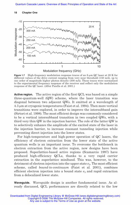
High-speed modulation of quantum cascade lasers and mode lockinghave been the subject of intense investigations by a group of researchersat Bell Labs led by Capasso in recent years (Paiella et al. 2000, 2001).Among all these brilliant experiments, we would like to draw attentionto the small-signal analysis of a laser under high-frequency modulation.The data in Fig. 1.7 are a clear demonstration of the absence of relax-ation oscillation resonance for QC lasers. This is direct experimentalevidence that the bandwidth of these lasers will be ultimately deter-mined by the photon lifetime in the cavity rather than the resonantcoupling between the photon field and the optical gain, as inconventional diode lasers.
In parallel, a new type of QCL emerged in 2002 (Köhler et al. 2002)—the terahertz laser emitting in the far infrared at a wavelength ofaround 100 μm ( = 3 THz). These devices are discussed in the nextsection.
This rapid progress is the result of intense research, complex quan-tum engineering, and technological developments in active region andwaveguide designs, in the growth of optimized heterostructurematerials, and in device processing. We try to summarize hereafter thecontributions that we feel are more important in each of the fields justmentioned.
Any use is subject to the Terms of Use as given at the website.
Quantum Cascade Lasers: Overview of Basic Principles of Operation and State of the Art
Active region. The active region of the first QCL was based on a simplethree-quantum-well (QW) scheme, where the laser transition wasdiagonal between two adjacent QWs. It emitted at a wavelength of4.3 m at cryogenic temperatures (Faist et al. 1994). Then more verticaltransitions were explored, in order to improve the intersubband gain(Sirtori et al. 1998). The most efficient design was commonly consideredto be a vertical intersubband transition in two coupled QWs, with athird very thin QW in the injection barrier. The role of the latter QW isto selectively enhance the amplitude of the excited state of the laser inthe injection barrier, to increase resonant tunneling injection whilepreventing direct injection into the lower states.
For high-temperature and high-power operation of QC lasers, theefficiency of electron extraction from the lower state of the activequantum wells is an important issue. To overcome the bottleneck inelectron extraction from the active region, new designs have beenproposed. Superlattice-based active regions (Scamarcio 1997) haveproduced high-efficiency QCLs, thanks to a very rapid carrierextraction in the superlattice miniband. This was, however, to thedetriment of electron injection into the upper state e3. The most efficientscheme, called bound-to-continuum (Faist et al. 2001), combinesefficient electron injection into a bound state e3 and rapid extractionfrom a delocalized lower state.
Waveguide. Waveguide design is another fundamental issue. As al-ready discussed, QCL performances are directly related to the low
-10
-2020 K
300 mA
250 mA
200 mA
150 mA
-30
-40
-50
-60
0 1
Modulation frequency (GHz)
Mo
du
latio
n r
esp
on
se
10
Figure 1.7 High-frequency modulation response traces of an 8- m QC laser at 20 K fordifferent values of the drive current ranging from very near threshold (150 mA), up toone order of magnitude higher photon density (300 mA). These traces were normalizedto the experimental frequency response of the receiver and reflect only the modulationresponse of the QC laser. (After Paiella et al. 2001.)
Any use is subject to the Terms of Use as given at the website.
Quantum Cascade Lasers: Overview of Basic Principles of Operation and State of the Art
optical losses of the laser cavity. The undisputable champion for highperformance in the mid-infrared range is the InP material used as op-tical cladding layers. It is a binary compound that provides a largedielectric refractive index contrast with the active region. In addition,InP has high electrical and thermal conductivity, without the need fora high doping level and therefore allows very low free-carrier opticallosses. For this reason, QCLs made of materials grown on InP haveconsiderable advantages. Alternative materials can, however, havetheir interest in specific cases. This material issue for QCL is discussedin greater detail in the following sections.
Growth. QCLs are very demanding devices in terms of heterostructuregrowth. Molecular beam epitaxy, with atomic monolayer control, isthe technique of choice for their fabrication. The evolution of laserperformances was directly related to the progress in growth quality.The question of growth rate stability is very important for the controlof the emission wavelength. Short-term stability (hour scale) impactsthe homogeneity of all periods of the active region and consequently theoptical gain.
The question of interface roughness, due to atomic intermixing orsegregation, is of great relevance (Offermans et al. 2003). First, itinduces inhomogeneous broadening of the intersubband transition andconsequently of the gain curve. In addition, interface fluctuations createa scattering potential in the plane of the epilayers. This is the cause ofelastic scattering of electrons in the active region of the QCLs, whichaffects the electron dynamics and possibly the lifetime of electrons inthe excited state (Leulliet et al. 2005).
Most important is certainly the decrease of epitaxial defects andsubsequent reduction of optical losses. The more advanced realizationsare the monolithic growth of complete QCL structures including activeregion and high-purity cladding layers (Evans et al. 2004a) whichreduced optical losses to few cm 1. This appears to be the key for thefabrication of very high-performance devices.
Processing. Beyond the conventional ridge geometry, solutions havebeen proposed to manage the dissipation of the high thermal powergenerated in the active part of QCLs. The reduction of the total area ofQC devices, without the addition of extra waveguide losses, is one ofthe most important issues presently under investigation. To this end,two processing technologies are under development: (1) the conven-tional buried heterostructure used by Beck and coworkers (Beck et al.2002) and (2) the selective current channeling by ion implantationrecently demonstrated at the corporate laboratory of THALES (Sirtoriet al. 2002). By exploiting this second way of realizing devices Page
Any use is subject to the Terms of Use as given at the website.
Quantum Cascade Lasers: Overview of Basic Principles of Operation and State of the Art
et al. were able to demonstrate cw operation of GaAs-based quantumcascade lasers up to 150 K (Page et al. 2004). Additional thick electro-plated gold on the top contact is another way to spread the heat awayfrom the active region (Evans et al. 2004a, Forget et al. 2005).
Monomode emission from distributed feedback (DFB) QCLs has beenobtained on InP (Faist et al. 1997) and on GaAs (Schrenk 2000). Withsuch technology, QCLs are a new class of single-mode sources availablefor applications to chemical sensing or pollution monitoring, ofparticular interest in the 3- to 5- m and 8- to 12- m ranges. Theimplementation of photonic crystals is another field explored towardmore compact or surface-emitting QC devices (Colombelli et al. 2003).QC lasers are a very attractive light source for molecular spectroscopywhen they are processed into distributed feedback lasers for wave-length control and stabilization. In Fig. 1.8 the spectra of GaAs-basedQC lasers, mounted on a Peltier cooler, are shown. Notice that theemission wavelength varies as function of the temperature, due to thechange of the material’s refractive index. This is a very importantparameter that allows one to fine-tune the emission frequency with
has been measured in different experiments and gives a value in the2 to 5 MHz (Kosterev and Tittel 2002, Blaser et al. 2001). Whenstabilized by means of an electronic feedback loop, for high-stability
1040
0.1
0.01
0.001
0.0001
1050 1060 1070
+35°c
Device size:1.5 mm x 30 μm
Spectra at maximum optical power
Inte
nsi
ty (
arb
. units
)
Wave number (cm-1)
+20°c
-20°c
-40°c
0°c
Figure 1.8 QC laser spectra of a device processed into DFB. The device operates in pulsedmode (100 ns, 5 kHz) and is mounted on a Peltier element where the temperature isvaried between –40 and +35°C. The peak position red-shifts with temperature;therefore the far left curve corresponds to +35°C and that on the far right to –40°C.The peak optical power is in excess of 100 mW at all temperatures. Note that inthis temperature range the device can be tuned over 5 cm 1. (After Sirtori and Nagle2003.)
20 Chapter One
the molecular resonance. The linewidth of free-running DFB lasers
Any use is subject to the Terms of Use as given at the website.
Quantum Cascade Lasers: Overview of Basic Principles of Operation and State of the Art
operation, these devices have shown lines with intrinsic width wellbellow 1 kHz (Myers et al. 2002).
Applications. As they produce compact light sources of coherent radi-ation working cw at room temperature in the mid-infrared range, fromwavelengths of 4 to 10 m, QCLs become attractive for many applica-tions in this spectral range such as gas-sensing, free-space opticalcommunications, or optical countermeasures. In the terahertz range,molecular spectroscopy or imaging applications promise the potentialfor long-wavelength QCLs.
Gas-sensing applications include, for example, trace gas detection,pollution or process monitoring, isotope separation, etc. Monomodelasers with narrow spectral width and high side mode suppressionratio are needed for spectroscopic applications. The tunability of theemission wavelength is an important property, obtained through thecurrent-induced temperature shift of the laser line. High-T operation isalso required for most applications. Continuous-wave operation is in-dispensable for high-resolution spectroscopic applications. However, cwoperation is not absolutely necessary, as demonstrated by the companyCascade Technology. It developed a QCL-based spectroscopic systemable to acquire the entire spectrum over one single current pulse(Stevenson 2004).
Free-space communications can also benefit from QCL sourcesemitting in the 3- to 5- m and 8- to 12- m atmospheric windows. Longerwavelengths are theoretically better because they are less sensitive toRaleigh scattering or bad atmospheric conditions.
QCLs are also proposed as candidates for optical countermeasures.However, for such applications consisting of deceiving or blindingadverse infrared sensors, emitted power is still an issue. The versatilityof QCL technology and its ability to produce multiwavelength sourcescould be an advantage in this domain.
As far as commercial applications are concerned, new perspectiveshave appeared with the first MOCVD-grown QCLs (Green et al. 2003).This technique provides a more reliable and industrial-friendlyapproach for QCL fabrication. Despite its presumed impossibility toproduce sharp interfaces, rapidly improving performances of MOCVD-grown QC lasers are reported (Troccoli et al. 2005a).
1.3.2 Frontiers
Beyond the conventional mid-infrared QC lasers of increasing matu-rity, new frontiers are being explored. Thanks to the flexibility of theactive region and the cascading scheme, new functionalities or phe-nomena can be explored inside the laser cavity, such as nonlinear optics
Any use is subject to the Terms of Use as given at the website.
Quantum Cascade Lasers: Overview of Basic Principles of Operation and State of the Art
or Raman lasing (Troccoli et al. 2005b). However, one of the most at-tractive research areas is at the frontiers of the emission spectrum, toextend the spectral width of QC laser operation. The long-wavelengthside is the emerging field of terahertz lasers, which opens new perspec-tives in terms of imaging or molecular spectroscopy. On the other endof the spectrum, short-wavelength QCLs ( < 4 m) could be the candi-date to fulfill the lack of semiconductor laser sources operating at roomtemperature in the 3 to 4 m range.
New physics. The high intensity of optical field in the cavity of QCLsallows generation of intracavity nonlinear effects. Nonlinearity canoriginate either from the semiconductor crystal itself or from specifi-cally designed structures inserted in series with the active region.Frequency doubling has been demonstrated (Owschimikow et al. 2003)as well as sideband generation (Dihlon 2005).
The coherent light generated in the QCL cavity can also be used topump intersubband transitions and generate emissions at differentwavelengths. This principle gave birth to the intracavity Raman laser(Troccoli 2005b).
Terahertz domain. In only a couple of years, since the first demonstra-tion in 2002 (Köhler et al. 2002), the progress on QC terahertz lasershas been astonishing. Not only has the wavelength range been extended
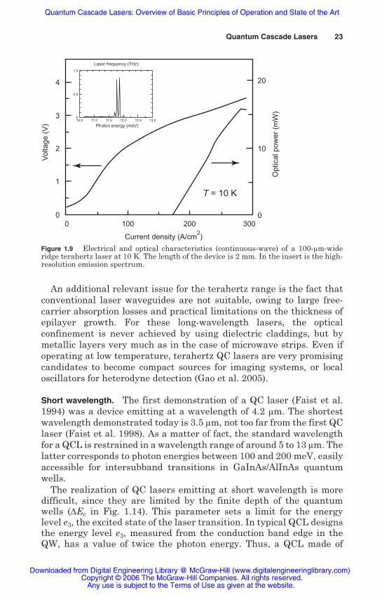
continuous-wave, terahertz devices operate a few degrees above liquidnitrogen, and in pulsed-mode they reach 140 K (Williams et al. 2005).In Fig. 1.9 we report V-I and L-I characteristics at temperatureT = 10 K of a device with an emission wavelength of 103 m (2.9 THz)(Alton et al. 2005).
The principles of operation of terahertz QC lasers relie on ratherdifferent concepts than do devices in the mid-infrared, which takeadvantage of electron-LO-phonon scattering processes above thematerial reststrahlenband to achieve large population inversions. Alsofor terahertz lasers, efficient depletion of the lower level is essential,while long lifetimes of the upper level are highly desirable. To this end,terahertz active regions are designed to have the optical transition,with a large dipole matrix element, across a minigap 10 to 15 meV wide.The lower laser state is strongly coupled to a wide injector miniband(comprising a high number of subbands), which provides a large phasespace where electrons scatter, thus ensuring a fast depletion of thelower state of the laser transition. Moreover, the minibands allowefficient electrical transport, even at high current densities, andsuppress thermal backfilling.
22 Chapter One
by more than a factor of 2 from 67 to 150 m (Worral et al. 2005),but also the operating temperatures have noticeably improved: In
Any use is subject to the Terms of Use as given at the website.
Quantum Cascade Lasers: Overview of Basic Principles of Operation and State of the Art
An additional relevant issue for the terahertz range is the fact thatconventional laser waveguides are not suitable, owing to large free-carrier absorption losses and practical limitations on the thickness ofepilayer growth. For these long-wavelength lasers, the opticalconfinement is never achieved by using dielectric claddings, but bymetallic layers very much as in the case of microwave strips. Even ifoperating at low temperature, terahertz QC lasers are very promisingcandidates to become compact sources for imaging systems, or localoscillators for heterodyne detection (Gao et al. 2005).
Short wavelength. The first demonstration of a QC laser (Faist et al.1994) was a device emitting at a wavelength of 4.2 m. The shortestwavelength demonstrated today is 3.5 m, not too far from the first QClaser (Faist et al. 1998). As a matter of fact, the standard wavelengthfor a QCL is restrained in a wavelength range of around 5 to 13 m. Thelatter corresponds to photon energies between 100 and 200 meV, easilyaccessible for intersubband transitions in GaInAs/AlInAs quantumwells.
The realization of QC lasers emitting at short wavelength is moredifficult, since they are limited by the finite depth of the quantumwells ( Ec in Fig. 1.14). This parameter sets a limit for the energylevel e3, the excited state of the laser transition. In typical QCL designsthe energy level e3, measured from the conduction band edge in theQW, has a value of twice the photon energy. Thus, a QCL made of
4
3
2
1
Vo
ltag
e (
V)
Op
tica
l po
we
r (m
W)
00 100
Current density (A/cm2)
200
T = 10 K
3000
10
20
Laser frequency (THz)
Photon energy (meV)10.5 11.0
1.0
0.5
012.0 13.011.5 12.5
Figure 1.9 Electrical and optical characteristics (continuous-wave) of a 100- m-wideridge terahertz laser at 10 K. The length of the device is 2 mm. In the insert is the high-resolution emission spectrum.
Any use is subject to the Terms of Use as given at the website.
Quantum Cascade Lasers: Overview of Basic Principles of Operation and State of the Art
GaAs/AlGaAs materials with Ec = 0.36 eV will not be able to operatewith photons of energy greater than 0.18 eV, that is, below a wavelengthof 7 m.
This limitation on the short wavelength is fundamental anddependent on the materials. Alternative materials presenting higherconduction band discontinuities are required to achieve QC laseremission below 4 m. This is the main motivation of most of the researchon new material systems for QCLs presented below.
1.3.3 Results on different materials
By nature, the concept of a QC laser does not depend on the choice ofthe well and barrier materials that constitute the heterostructure.However, material-dependent properties will play a significant role inthe device characteristics, through their influence on barrier heights,scattering mechanisms, waveguide properties, etc.
The different III-V materials that have been investigated for QClasers are presented in Fig. 1.10. Among all the possible combinationstwo material systems have been already amply exploited to produce QClasers: InGaAs/InAlAs grown lattice matched on indium phosphide(InP) substrate and GaAs/AlGaAs grown on gallium arsenide (GaAs)substrate.
Lattice constant (Å)
Ene
rgy
ga
p (
eV
)
5.4 5.6 5.8 6.0
GaAs
GaSb
AlAsGaP
AlSb
InAs
InSb
6.2 6.4
0.0
1.0
1.5
2.0
2.5
0.5
AlInAs
GaInAs
AlAsSb
InP
Figure 1.10 The different III-V material systems, as defined by their lattice constants.The heterostructures that have been already used to realize quantum cascade lasers areindicated by the dashed ovals.
Any use is subject to the Terms of Use as given at the website.
Quantum Cascade Lasers: Overview of Basic Principles of Operation and State of the Art
InGaAs/InAlAs on InP. This is the historical material system in whichthe laser was first demonstrated (Faist et al. 1994). In the mid-infrared,
the best-performing solution for QC lasers. Today, they cover the spec-trum from 3.6 to 24 m. CW operation at room temperature is obtainedfrom = 4.3 m (Yu et al. 2005) to = 9.6 m (Beck et al. 2002).
With a Ec of 0.52 eV, the standard InP system fails to produce high-performance QCLs below 6 m. However, its spectral range can be
materials, with increased indium content in the InGaAs wells andincreased aluminium content in the InAlAs barriers. This provides alarger band discontinuity of 650 to 750 meV as a function of the In and
materials have shown performances of 300-mW continuous-waveemission at a wavelength of 4.8 m at room temperature (Evans et al.2004b) and 160 mW at = 4.3 m (Yu et al. 2005). DFB lasers operatingcw at room temperature have also been realized with InP-based QCLs,first at a wavelength of 5.4 m (Blaser et al. 2005).
GaAs. A few years later, GaAs-based QCLs were demonstrated (Sirtoriet al. 1998a). They now range from 8 m to the terahertz domain atwavelengths up to 160 m. In the mid-infrared, this material systemhas less interesting performance that of InP-based materials. The ma-jor drawback is the relatively higher threshold at room temperature(Jth
GaAs 5JthInP) which makes cw operation almost impossible for these
devices above 200 K. On the long-wavelength side, GaAs becomes betterperforming than InP fundamentally for reasons of material purity,which dramatically increase the mobility and the conductivity of thesemiconductor at low temperature and guarantee lower waveguidelosses. This has allowed the birth and development of the terahertz QClasers (Köhler et al. 2002).
Antimonides at 6.1 Å. Antimonide compound semiconductors are thefamily of III-V materials with a crystal lattice constant of about 6.1 Å(Fig. 1.10), which can be grown lattice-matched on gallium antimo-nide (GaSb) or indium arsenide (InAs) substrates. This family in-cludes the three binary compounds InAs, GaSb, and AlSb and theiralloys.
The most interesting property of antimonides for the design ofQCL is the remarkably large depth of InAs QW with AlSb barriers
Ec = 2.1 eV. In principle, it should enable the design of very short-wavelength QCLs down to the near-infrared range (1.5 m). Theavailable QW depth is, however, limited by the position of the lateralvalleys (X or L) of the Brillouin zone. The L valley is 800 meV above the
Quantum Cascade Lasers 25
InGaAs/AlInAs quantum wells lattice matched on InP substrates are
extended toward short wavelengths by using strained compensated
Al content. As a matter of fact, QCL devices made of these strained
Any use is subject to the Terms of Use as given at the website.
Quantum Cascade Lasers: Overview of Basic Principles of Operation and State of the Art
conduction band edge in InAs. Therefore, the emission range for thisnovel material system is probably restricted to wavelengths greaterthan 3 m. Other specific issues for the realization of short-wavelengthQCLs are presented in Sec. 1.4.
A second specificity of antimonides is the very small effective massin InAs. This leads to significantly stronger intrinsic intersubbandoptical gain, compared to other material systems (see Fig 1.13 below).Hence, from a material point of view, it is clear that antimonides are avery attractive system for mid-infrared QCLs.
In spite of the very high conduction band discontinuity, the first QClaser demonstrated in this material system was at 10 m (Ohtani andOhno 2003). More recently the potential of this heterostructure hasbeen better exploited and lasers emitting at ~4 m have beendemonstrated up to room temperature (Teissier et al. 2004). Eventhough the performances of these devices are very encouraging, theyhave not yet reached those of the QC laser based on InP. We cannotaddress any fundamental reasons for this, but just remind that thesevery recently born devices need more work and optimization.
InGaAs/AlAsSb on InP. An intermediate solution has been proposedand developed from 2003—to use the antimonide alloy AlAsSb lattice-matched on InP (Fig. 1.10) as a barrier material with InGaAsas the well material both lattice-matched on InP. This heterostructurebenefits both from the advantages of the InP system and froma high Ec provided by the AlAsSb barriers. It is, in our opinion, a veryattractive material choice for the short wavelengths, for the most partfor technological reasons related to the maturity of the processingand InP waveguide claddings. In principle, however, GaInAs has ahigher mass and lower lateral valley energy than InAs, which shouldgive lower gain and reduced effective QW depth. QCLs made ofthese InGaAs/AlAsSb materials were realized for the first time in2004 (Revin et al. 2004). The devices emitted at = 4.3 m in pulsedmode up to a temperature of 240 K. Recently, very high-temperatureoperation of similar devices around = 4.5 m has been reported (Yanget al. 2005).
Si/SiGe. For Si/SiGe the steps toward a unipolar laser are less ad-vanced. Nevertheless, intersubband electroluminescence has been re-cently observed from QC active regions realized on metamorphicsubstrate Si0.5Ge0.5 (Diehl et al. 2002). The realization of QC lasersin Si/SiGe would represent a major breakthrough simply because itwould represent the first laser based on Si. In this material system,intersubband transitions occur in the valence band, which is a seriouscomplication from the point of view of the theoretical description.
Any use is subject to the Terms of Use as given at the website.
Quantum Cascade Lasers: Overview of Basic Principles of Operation and State of the Art
Moreover, the presence of the different hole dispersions (heavy, light,and split off) increases enormously the number of subbands and makesit more difficult to control their energy separation. Even if prelimi-nary, these recent results on electroluminescence represent, in ouropinion, the closest yet to the demonstration of a Si-based semiconduc-tor laser.
1.4 Material Issues
1.4.1 Fundamental Parameters m* and Ec
In Sec. 1.1 and in particular in the paragraph where we describe ourdefinition of quantum engineering, we insist on the minor dependencethat the quantum cascade laser concept has on the material parametersof the heterostructure. Indeed, there are some physical parameters, re-lated to the material system, that have a direct influence on the lasercharacteristics. At the first order, there are two parameters originatingfrom the heterostructure that have to be taken into account: the con-duction band discontinuity Ec and the effective mass of the wellmaterial m*.
1.4.2 Role of the effective mass m*
The role of m* is complex, but can be easily illustrated by analyzingthe formula of the gain (Eq. 1.24). We take the expression of thegain coefficient g and compare its value for two material systems: GaAsand InAs. Moreover, to reduce the influence of the active region designand have a fair comparison of the two materials, we apply this formulato the first two states (E1 and E2) of a quantum well with veryhigh barriers (Fig. 1.11). In the limit of 2 << 32 (or 1 << 21 in thepresent two-level picture), normally very well satisfied at low temper-ature, and with unity injection g can be written as
g =4 e
0n 2 L p|z21|2
2 = 2e
0nc1
2 L pE21 2 |z21|2
= e
0cm0
12 nL p
f21 2
(1.29)
In this expression the effective mass has a direct influence on thethree terms on the right, namely, the transition energy E21, the squareddipole matrix element, |z21|2, and the lifetime of the excited state ofthe laser transition 2. If we set the transition energy to a fixed valuefor both materials, for instance, 124 meV ( = 10 m), then the quantity
Any use is subject to the Terms of Use as given at the website.
Quantum Cascade Lasers: Overview of Basic Principles of Operation and State of the Art
1/m*L2 is identical in the two materials, where L is the width of thequantum well.
Therefore the lighter the mass, the wider is the quantum well, asschematically illustrated in Fig. 1.11. It can be easily demonstratedthat in a quantum well the absolute value of the dipole matrix element|z21| is proportional to L. Thus it can be concluded that for a givenmaterial the square of the dipole matrix element is inverselyproportional to the effective mass. If we now concentrate on 2, theexcited state lifetime, we can safely assume that it is merely controlledby the electron optical-phonon interaction. In this case it can be shownthat 2 depends on the inverse of the square root of the mass. Insummary, the gain coefficient g is
which means that the gain coefficient is proportional to (m*) 3/2 and thatthe ratio of the gain coefficients of the two materials InAs and GaAs canbe evaluated to
gInAs
gGaAs =mGaAs
mGaInAs
3 / 2
= 0.0670.023
3 / 25 (1.31)
This example evidently illustrates the strong dependence of the gainon the effective mass. However, the full picture is more complicated dueto the effect of the conduction-band nonparabolicity that makes theelectronic effective mass a function of the energy m* = m E). This effectarises from the coupling of the electronic wave functions with those ofthe valence bands, and it is more pronounced for materials with smallgaps, such as InAs. To calculate the energy-dependent effective mass,we used a simplified 3×3 Kane hamiltonian which describes theconduction, light-hole, and split-off bands, since near the point theheavy-hole band is decoupled from the others (Sirtori et al. 1994). Thevalue of m* as a function of the energy for different material systems is
GaAsm* = 0.067
InAsm* = 0.024
E1
E2
E3 3E
21 =h2π2
2 m L2
L = 115 Å L = 189 Å
Figure 1.11 Quantum wells made of different materials. Notice that if we fix the energyseparation E21 the width of the quantum well is inversely proportional to m*.
Any use is subject to the Terms of Use as given at the website.
Quantum Cascade Lasers: Overview of Basic Principles of Operation and State of the Art
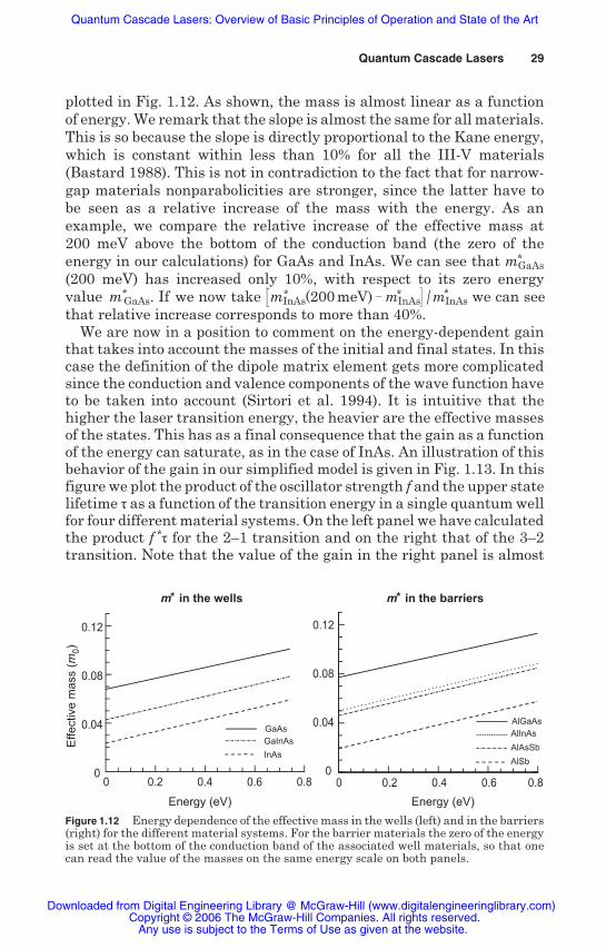
plotted in Fig. 1.12. As shown, the mass is almost linear as a functionof energy. We remark that the slope is almost the same for all materials.This is so because the slope is directly proportional to the Kane energy,which is constant within less than 10% for all the III-V materials(Bastard 1988). This is not in contradiction to the fact that for narrow-gap materials nonparabolicities are stronger, since the latter have tobe seen as a relative increase of the mass with the energy. As anexample, we compare the relative increase of the effective mass at200 meV above the bottom of the conduction band (the zero of theenergy in our calculations) for GaAs and InAs. We can see that m*
GaAs(200 meV) has increased only 10%, with respect to its zero energy
We are now in a position to comment on the energy-dependent gainthat takes into account the masses of the initial and final states. In thiscase the definition of the dipole matrix element gets more complicatedsince the conduction and valence components of the wave function haveto be taken into account (Sirtori et al. 1994). It is intuitive that thehigher the laser transition energy, the heavier are the effective massesof the states. This has as a final consequence that the gain as a functionof the energy can saturate, as in the case of InAs. An illustration of thisbehavior of the gain in our simplified model is given in Fig. 1.13. In thisfigure we plot the product of the oscillator strength f and the upper statelifetime as a function of the transition energy in a single quantum wellfor four different material systems. On the left panel we have calculatedthe product f * for the 2–1 transition and on the right that of the 3–2transition. Note that the value of the gain in the right panel is almost
Figure 1.12 Energy dependence of the effective mass in the wells (left) and in the barriers(right) for the different material systems. For the barrier materials the zero of the energyis set at the bottom of the conduction band of the associated well materials, so that onecan read the value of the masses on the same energy scale on both panels.
Quantum Cascade Lasers 29
m* in the barriers
Effe
ctiv
e m
ass
(m
0)
Energy (eV) Energy (eV)
m* in the wells
GaAs
GaInAs
InAs
AlGaAs
AlInAs
AlAsSb
AlSb
0
0.04
0.08
0.12
0
0.04
0.08
0.12
0 0.2 0.4 0.6 0.8 0.2 0.4 0.6 0.80
value m*GaAs. If we now take mInAs(200 meV) mInAs / mInAs we can see
that relative increase corresponds to more than 40%.* * *
Any use is subject to the Terms of Use as given at the website.
Quantum Cascade Lasers: Overview of Basic Principles of Operation and State of the Art
twice that on the left, showing the importance of designing lasersbetween excited states.
1.4.3 Role of the conduction banddiscontinuity Ec
At first glance, the role of Ec is self-evident and defines the highestphoton energy achievable in a given material system, as mentionedearlier. Therefore, the range in which the emission wavelength of theQC laser can be tuned by adjusting the width of the layers is finite andhas an upper limit set by the depth of the quantum wells. Nonetheless,on the long-wavelength side, there are no fundamental limits prevent-ing the fabrication of QC lasers emitting in the far-infrared. Apart fromthe wavelength range, there are less evident effects controlled by Ecthat need to be mentioned.
Escape to the continuum. When a confined level gets closer to the top ofthe barriers, the probability of thermal activation of electrons to a de-localized state increases dramatically (Fig. 1.14). The scattering rate ofan electron out of the confined state e3 is controlled by the occupationprobability in the subband at an energy greater than that of the top ofthe barrier, and by the typical scattering time scatt from this subband.The model to describe this effect is identical to the one used for calcu-lating dark current in quantum well infrared photodetectors (QWIPs)(Liu et al. 1993).
The two-dimensional density of electrons localized in the quantumwell and with energy greater than Ec is given by
Figure 1.13 The product f· between levels 2 and 1 is plotted on the left, and betweenlevels 3 and 2 on the right. The quantity f· directly proportional to the gain.
Any use is subject to the Terms of Use as given at the website.
Quantum Cascade Lasers: Overview of Basic Principles of Operation and State of the Art
n2D = n3exp( Ec e3
kTe) (1.32)
where n3 is the total sheet density in level e3, and Te is the electrontemperature. It has been measured (Spagnolo et al. 2004) to besensibly greater than the lattice temperature by a value on the orderof 100 K.
The leakage current density to the continuum is then simply givenby
Jesc =qn2D
scatt(1.33)
The important issue is the estimation of the scattering time. It canbe derived from the drift velocity and mean transit time of unboundelectrons over the quantum well, as usually assumed in QWIP theory.In the case of QCLs, however, the band structure of the active region ismuch more complex with a large number of confined states, and theapplied electric field is far greater than the one in QWIPs. For thesereasons, we can neglect the probability of electron recapture to the ini-tial state. The time scatt is then the mean scattering time of the confinedstate to a continuum of states. We can safely assume that in InGaAs/InAlAs structures scatt is dominated by LO phonon scattering and is onthe order of 0.2 ps.
This escape current has to be compared to the cascade current Jcwhich is governed by LO phonon scattering to the lower subbands. Theelectron lifetime in the excited state of the active region 3 is on the orderof 1 ps, and its temperature dependence is given by the variation of thephonon population
e1e2
e3
?Ec
Figure 1.14 Schematic representation of a QC laser active region. The arrow indi-cates the path of electrons that, due to thermal effects, are activated into the continuumstates.
Any use is subject to the Terms of Use as given at the website.
Quantum Cascade Lasers: Overview of Basic Principles of Operation and State of the Art
3 = 3(0)
1 + 2 / exp( LO / kT) 1(1.34)
The calculated ratio of leakage current density to the cascade currentis shown in Fig. 1.15 for InGaAs/InAlAs QC lasers lattice-matched onInP, as a function of emission wavelength. For room temperature op-eration, the limit set by the escape current is around 4.5 to 5 m.
The effective activation energy can be modified by the presence ofminigap or quasi-bound states in the continuum density of states, dueto quantum interference with the quantum wells. These effects havebeen reviewed in Faist et al. (2000).
When a high electric field is applied, a lowering of the barrier occurs.Moreover, due to tunneling the continuum states penetrate into theactive region, thus also modifying the effective activation energy. Allthese effects contribute to make the design of short-wavelength QClasers more and more difficult.
Injector barrier transparency. The basis of QC laser engineering is thecontrol of the coupling between adjacent QWs. In that respect the banddiscontinuity Ec is a critical parameter, since it sets the transparencyof the barriers. The wave function decay rate in the barrier for a levelof energy E is given by
kB =2mB
* (E)2 ( Ec E) (1.35)
0 50 100 150 200 250 300 350 4000
1
2
3
J esc/Jc
Temperature (K)
λ ~ 4.3 μm
(e3 - ΔEc = 30 meV)
λ ~ 4.5 μm
(e3 - ΔEc = 50 meV)
λ ~ 5 μm
(e3 - ΔEc = 100 meV)
Figure 1.15 Ratio between the current in the active region and the leakage current dueto the thermal leakage in the continuum. It is clear that for activation energy smallerthan 50 meV, room temperature operations are completely hindered by the thermalactivated current.
Any use is subject to the Terms of Use as given at the website.
Quantum Cascade Lasers: Overview of Basic Principles of Operation and State of the Art
where mB* (E) is the energy-dependent effective mass in the barrier
material. The transmission of the barrier is proportional to the atten-uation of the squared wave function over the thickness of the barri-er LB.
TB exp( 2kBLB) (1.36)
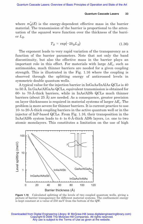
The exponent leads to very rapid variation of the transparency as afunction of the barrier parameters. Note that not only the banddiscontinuity, but also the effective mass in the barrier plays animportant role in this effect. For materials with large Ec, such asantimonides, much thinner barriers are needed for a given couplingstrength. This is illustrated in the Fig. 1.16 where the coupling isobserved through the splitting energy of anticrossed levels insymmetric double quantum wells.
A typical value for the injection barrier in InGaAs/InAlAs QCLs is 40to 50 Å. In GaAs/AlGaAs QCLs, equivalent transmission is obtained for60- to 70-Å-thick barriers, while in InAs/AlSb QCLs much thinnerbarriers (about 25 Å) are needed. As a consequence, greater precisionon layer thicknesses is required in material systems of larger Ec. Theproblem is more severe for thinner barriers. It is current practice to use10- to 20-Å-thick coupling barriers in the active quantum well or in theinjector of InP-based QCLs. From Fig. 1.16, their transposition in theInAs/AlSb system leads to 4- to 6-Å-thick AlSb layers, i.e. one to twoatomic monolayers. This constitutes a limitation on the use of high
0 20 40 60 80 100 120
1
10
100
InGaAs/AlAsSb
InAs/AlSb
InGaAs/InAlAs
Δ
Le
vel s
plit
ting
(m
eV
)
Barrier thickness (Å)
GaAs/AlGaAs
Figure 1.16 Calculated splitting of the levels of two coupled quantum wells, giving apicture of barrier transparency for different material systems. The confinement energyis kept constant at a value of 250 meV from the bottom of the QW.
Any use is subject to the Terms of Use as given at the website.
Quantum Cascade Lasers: Overview of Basic Principles of Operation and State of the Art
Ec materials. In that respect, optimum design schemes may besignificantly different in these alternative material systems.
The absolute barrier thicknesses also influence the inhomogeneousbroadening of confined levels and the associated interface roughnessscattering mechanisms. A fluctuation of one atomic monolayer will leadto a larger shift of intersubband transitions when thinner barriers areused. In a similar way, interface scattering is expected to be moreimportant for higher barriers, since a given thickness roughness willproduce a larger scattering potential. However, these mechanisms aredeeply linked to the microscopic structure of the interfaces, which isvery dependent on the material system and on the growth conditions.
InP- or GaAs-based structures have been reported in InAs/AlSbstructures (Barate et al. 2005).
Terahertz QCLs require very thick quantum wells. For this reasonthe electron wave functions have a very small amplitude in the barriers,and adjacent QWs are much less coupled than in mid-infrared QClasers. In this case, too, thinners barriers are necessary. One advantageof the GaAs system for terahertz lasers is the possibility of reducing theheight of AlGaAs barriers by reducing the Al content of the ternaryalloy. Typical values of 15% Al content are used to avoid the problemsinherent in too thin barriers.
1.4.4 Lateral valleys
Effective barrier height. The presence of lateral valleys can be anotherlimitation to short-wavelength operation of QC lasers. Heterostructurequantum states are built independently from each minimum of theconduction band in the k·p theory (Bastard 1988). However, if the statesassociated with lateral valleys have an energy close to that of the states of the active region, a possible intervalley transfer can occur anddeteriorate the gain of the laser.
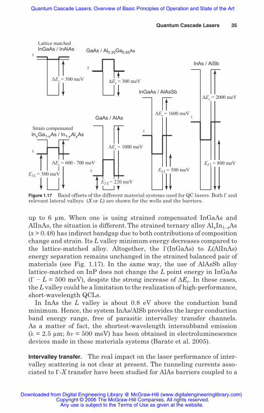
The positions of the relevant lateral valley minima are shown inFig. 1.17 for the different material systems. The large conduction banddiscontinuity of GaAs/AlAs cannot be fully exploited because of itsindirect bandgap and the presence of X valley confined states in theAlAs barriers. Tunneling channels introduced by X states have beenobserved experimentally and extensively studied (Finley et al. 1998).They can produce significant leakage currents for electrons of energygreater than 200 meV. For this reason, GaAs-based QCLs use onlydirect gap barrier with Al content of 30% to 40%.
In an InGaAs/AlInAs system, lateral valley minima L and X are closeto the top of the barriers and are not a main limitation for wavelenghs
34 Chapter One
In practice, intersubband emission linewidths comparable to those of
Any use is subject to the Terms of Use as given at the website.
Quantum Cascade Lasers: Overview of Basic Principles of Operation and State of the Art
up to 6 m. When one is using strained compensated InGaAs andAlInAs, the situation is different. The strained ternary alloy AlxIn1 xAs(x > 0.48) has indirect bandgap due to both contributions of compositionchange and strain. Its L valley minimum energy decreases compared tothe lattice-matched alloy. Altogether, the (InGaAs) to L(AlInAs)energy separation remains unchanged in the strained balanced pair ofmaterials (see Fig. 1.17). In the same way, the use of AlAsSb alloylattice-matched on InP does not change the L point energy in InGaAs( L = 500 meV), despite the strong increase of Ec. In these cases,the L valley could be a limitation to the realization of high-performance,short-wavelength QCLs.
In InAs the L valley is about 0.8 eV above the conduction bandminimum. Hence, the system InAs/AlSb provides the larger conductionband energy range, free of parasitic intervalley transfer channels.As a matter of fact, the shortest-wavelength intersubband emission( = 2.5 m; h = 500 meV) has been obtained in electroluminescencedevices made in these materials systems (Barate et al. 2005).
Intervalley transfer. The real impact on the laser performance of inter-valley scattering is not clear at present. The tunneling currents asso-ciated to -X transfer have been studied for AlAs barriers coupled to a
GaAs / Al0.35Ga0.65As
GaAs / AlAs
X
Lattice matched InGaAs / InAlAs
Strain compensated
InxGa1-xAs / In1-yAlyAs
L
L
InAs / AlSb
InGaAs / AlAsSb
L
L
X
ΔEc = 300 meV
ΔEc = 600 - 700 meV
EΓL = 500 meV
EΓX = 220 meV
EΓL = 500 meV
EΓL = 800 meV
ΔEc = 1000 meV
ΔEc = 1600 meV
ΔEc = 2000 meV
ΔEc = 500 meV
Figure 1.17 Band offsets of the different material systems used for QC lasers. Both andrelevant lateral valleys (X or L) are shown for the wells and the barriers.
Any use is subject to the Terms of Use as given at the website.
Quantum Cascade Lasers: Overview of Basic Principles of Operation and State of the Art
continuum of states (Finley et al. 1998). It has been shown to be domi-nant for thicker barriers and higher applied electric fields.
In the case of QC lasers, the lateral valley states are not coupled to acontinuum. When L or X states come below the point conductinglevels, the more likely transfer mechanism is a sequential hoppingtransport between X or L localized states. Intervalley scattering timeshave been demonstrated (Teissier et al. 1996) to be in the form
i j = 0
| i | X j |2 (1.37)
where the wave function overlap is calculated between the two local-ized states i and Xj and 0 is a constant scattering time, characteristicof the transfer mechanism. Typical values are 0 = 0.15 ps for elasticscattering to Xz valleys (in the growth direction) and 0 = 0.33 psfor phonon-assisted scattering to Xxy valleys (in the direction parallelto the layers). The situation should be significantly different dependingon whether these states are localized in the barriers or in thewells. In the first case, the overlap between state localized in thewells and X state localized in the barrier is small, leading to a slowintervalley transfer. In addition, coupling between X states in differentbarriers is also weak. The final result is a charge buildup in the bar-riers. On the contrary, in the case of X or L states localized in the wells,the overlap factor expressed in Eq. 1.37 is closer to unity, and moreefficient -X(L) transfer is expected. Therefore when the X or L valleyis localized in the well, the scattering in the lateral valley can giverise to an important parasitic leakage current, such as depicted inFig. 1.18.
The exploration of the short-wavelength limit of antimonide QCLs(InGaAs/AlAsSb or InAs/AlSb) could be a way of studying the realimpact of intervalley transfer, in a case where the escape of carriers tothe continuum is negligible because of the huge barrier height.
1.4.5 Waveguide
The waveguide design and its realization are crucial steps to obtainhigh-performance QC lasers. The vertical confinement of the opticalmode propagating in the cavity of the laser is obtained, as in most
by optical cladding layers made of low-refractive-index material.This is another aspect for which the material system impacts QCLperformances.
36 Chapter One
edge-emitting semiconductor lasers, by a multilayer structure: a corewaveguide made of the active region and spacer layers, surrounded
Any use is subject to the Terms of Use as given at the website.
Quantum Cascade Lasers: Overview of Basic Principles of Operation and State of the Art
The typical structure of a waveguide for a QC laser is presented inFig. 1.19. The intersubband transitions are only coupled to transversemagnetic (TM) polarized light (electric field prependicular to thelayers). The electric field intensity of the fundamental TM mode of thewaveguide is shown in the same figure. An important parameter todefine is the overlap factor , which is the percentage of the modeinteracting with the active region and can be written as
= AR
|E(z)|2 dz+
|E(z)|2 dz(1.38)
Figure 1.18 Schematic diagram of the and L conduction band profile in a short-wavelength InAs/AlSb QC structure, showing the relevant states issued from bothvalleys. The arrows show the possible intervalley leakage current mechanism.
Act
ive r
egio
n
Cla
ddin
g
Ref
ract
ive
index
Cla
ddin
g
Space
r
Space
r
Mode
inte
nsi
ty
Figure 1.19 Refractive index profile of a typical QCL waveguide, in the growthdirection z. The electric field intensity of the fundamental TM (electric field in the zdirection) mode is also shown.
Any use is subject to the Terms of Use as given at the website.
Quantum Cascade Lasers: Overview of Basic Principles of Operation and State of the Art
The gain of a QCL is proportional to the current density and to thisoverlap factor (Eq. 1.27). As a result, the laser threshold current densityis directly proportional to the cavity losses, which include waveguidelosses w and mirror losses m, and inversely proportional to the overlapfactor
gJth = w + m Jth = w + m
g(1.39)
A typical way to increase , and hence reduce threshold, is to increasethe number of periods in the active zone. This, however, increases theapplied voltage and therefore the total dissipated power injected intothe device. The main criterion to achieve a low-threshold QC laser isto find the waveguide that minimizes the optical losses andsimultaneously maximizes the overlap factor.
Due to the long wavelength a major contribution to optical losses isthe free-carrier absorption in the doped region of the waveguide, manlyin the cladding layers. These losses increase rapidly for longerwavelength and are the dominant factor for terahertz QC lasers. Theoptimum waveguide design depends both on the material system andon the wavelength range.
The InP-based system provides, with no doubt, the best waveguideproperties for mid-infrared QC lasers. The main advantages of thismaterial system stem from the possibility of using InP as claddingmaterial. In fact, due to its low refractive index and good electricalproperties, InP provides optical confinement without the need of highdoping concentration and therefore allow very low free-carrier opticallosses. Moreover, this is the only binary material that can be used ascladding, with very important consequences to the thermal resistanceof the devices. The thermal conductivity of InP (0.7 W/cm/K) is quitehigh, almost twice that of GaAs and at least 10 times higher than theternary or quaternary alloys, typically used for the optical confinementin waveguides grown on GaAs, InAs, or GaSb substrates. Nowadays,practically all the results relevant for technological applications arereferred to InP-based lasers.
In GaAs-based QCLs, the substrate index is higher than the index ofthe active region. Alternative materials must be used as claddinglayers. Different solutions have been proposed. The most straight-forward are the transpositions to the mid-ir of the waveguides used inthe near-ir GaAs-based diode lasers, using the alloys AlGaAs (Sirtoriet al. 1998) or GaInP (Green 2002) as cladding layers.
An alternative to dielectric waveguides (using low-dielectric-constantmaterial as cladding layers) was proposed in the early days of QCLhistory (Sirtori et al. 1995): a plasmon-enhanced waveguide using
Any use is subject to the Terms of Use as given at the website.
Quantum Cascade Lasers: Overview of Basic Principles of Operation and State of the Art
highly doped cladding layers. The low refractive index is obtainedthanks to the strong dispersion when the laser frequency gets close tothe plasma frequency of the doped material. This type of waveguide hasbeen efficiently applied to mid-infrared GaAs QCLs, either as a pureGaAs waveguide (Sirtori et al. 1999) or as AlGaAs waveguide enhancedby n+ GaAs plasmons (Sirtori et al. 1998). Its drawback is obviously itsintrinsic high optical losses, due to the highly doped layers. Thick, low-doped spacers are needed to separate the active region from the highlydoped layers, thus reducing the overlap factor.
Plasmon-enhanced waveguide is the solution for InAs systems too.Today, all InAs/AlSb QCLs have been made of n+-doped InAs claddinglayers (Ohtani and Ohno, 2003). For short-wavelength lasers, the free-carrier losses (proportional to 2) are reduced to a reasonable level, andhigh-performance waveguides with low loss ( w = 7 cm 1) and highconfinement factor ( = 47%) have been demonstrated at = 4.5 m(Teissier et al. 2004). The main limitation of the InAs-based waveguideis the small bandgap energy (Eg = 0.36 eV) of InAs, which prevents itsuse for wavelengths shorter than 4 m.
Waveguides for terahertz QCLs require different solutions. Dielectricwaveguides cannot be used due to the very long wavelength that wouldimpose the use of very thick layers. On the other hand, at terahertzfrequencies the very high free-carrier absorption prevents the use ofdoped layers. The solution is to use optical confinement through surfaceplasmons at metal semiconductor interfaces (Köhler et al. 2002). Theultimate confinement, with close to 100%, has been obtained in aterahertz QCL using double metal waveguides (Williams et al. 2003),analog to a mm-wave microstrip line.
References
Alferov, Zh. I., V. M. Andreev, E. L. Portnoi, M. K. Trukan, Fiz. Tekhn.Polupr. 3, 132 (1969); Sov. Phys. Semicond. 3, 1107 (1970).
Alton, J., S. Dhillon, A. de Rossi, M. Calligaro, H. E. Beere, S. Barbieri,E. Linfield, D. Ritchie, and C. Sirtori, “Buried waveguides via two dimensionalsurface plasmon modes in THz quantum cascade lasers,” Appl. Phys. Lett. 86,071109 (2005).
Barate, D., R. Teissier, Y. Wang, and A. N. Baranov, “Short wavelengthintersubband emission from InAs/AlSb quantum cascade structures,” Appl.Phys. Lett. 87, 051103 (2005).
Bastard, G., Wave Mechanics Applied to Semiconductor Heterostructures, LesEditions de Physique, Les Ulis, France, 1988.
Beck, M., D. Hofstetter, T. Aellen, J. Faist, U. Oesterle, M. Ilegems, E. Gini,and H. Melchior, “Continuous wave operation of a mid-infrared semiconductorlaser at room temperature,” Science 295, 301 (2002).
Any use is subject to the Terms of Use as given at the website.
Quantum Cascade Lasers: Overview of Basic Principles of Operation and State of the Art
Bewley, W. W., J. R. Lindle, C. S. Kim, I. Vurgaftman, J. R. Meyer, A. J. Evans,J. S. Yu, S. Slivken, and M. Razeghi, “Beam steering in high-power cw quantumcascade lasers,” IEEE J. Quantum Electron. 41, 833 (2005).
Blaser, S., L. Diehl, M. Beck, J. Faist, U. Oesterle, J. Xu, S. Barbieri, andF. Beltram, “Characterization and modeling of quantum cascade lasers basedon a photon-assisted tunneling transition,” IEEE J. Quantum Electron. 37, 448(2001).
Blaser, Stéphane, Dmitri A. Yarekha, Lubos Hvozdara, Yargo Bonetti, AntoineMuller, Marcella Giovannini, and Jérôme Faist, “Room-temperature,continuous-wave, single-mode quantum-cascade lasers at lambda 5.4 m,”Appl. Phys. Lett. 86, 041109 (2005).
Capasso, F., K. Mohamed, and A. Y. Cho, “Resonant tunneling trough doublebarriers, perpendicular quantum transport phenomena in superlattices,and their device applications,” IEEE J. Quantum Electron. 22, 1853–1869(1986).
Cho, A., Molecular Beam Epitaxy, AIP Press, Woodbury, NW, 1994.
Colombelli, R., K. Srinivasan, M. Troccoli, O. Painter, C. Gmachl, D. M.Tennant, A. M. Sergent, D. L. Sivco, A. Y. Cho, and F. Capasso, “Quantumcascade surface-emitting photonic crystal laser,” Science 302, 1374 (2003).
Diehl, L., S. Mentese, E. Müller, D. Grützmacher, H. Sigg, U. Gennser,I. Sagnes, Y. Campidelli, O. Kermarrec, D. Bensahel, and J. Faist,“Electroluminescence from strain-compensated Si0.2Ge0.8/Si quantum-cascadestructures based on a bound-to-continuum transition,” Appl. Phys. Lett. 81,4700 (2002).
Dhillon, S. S., C. Sirtori, S. Barbieri, A. de Rossi, M. Calligaro, H. E. Beere, andD. A. Ritchie, “THz sideband generation at telecom wavelengths in a GaAs-based quantum cascade laser,” Appl. Phys. Lett. 87, 071101 (2005).
Donovan K., P. Harrison, and R. W. Kelsall, “Self-consistent solutions to theintersubband rate equations in quantum cascade lasers: Analysis of a GaAs/AlxGa1–x As device,” J. Appl. Phys. 89, 3084 (2001).
Esaki, L., and R. Tsu, “Supperlattice and negative differential conductivity insemiconductors,” IBM J. Res. Devel. 14, 61–65 (1970).
Evans, A., J. S.Yu, J. David, L. Doris, K. Mi, S. Slivken, and M. Razeghi, “High-temperature, high-power, continuous-wave operation of buried heterostructurequantum-cascade lasers,” Appl. Phys. Lett. 84, 314 (2004a).
Evans, A., J. S. Yu, S. Slivken, and M. Razeghi, “Continuous-wave operationof ~ 4.8 m quantum cascade lasers at room temperature,” Appl. Phys. Lett.85, 2166 (2004b).
Faist, J., F. Capasso, D. L. Sivco, C. Sirtori, A. L. Hutchinson, and A. Y. Cho,“Quantum cascade laser,” Science 264, 553 (1994).
Faist, J., F. Capasso, C. Sirtori, D. L. Sivco, J. N. Baillargeon, A. L. Hutchinson,S.-N. G. Chu, and A. Y. Cho, “High power mid-infrared ( ~ 5 m) quantumcascade lasers operating above room temperature,” Appl. Phys. Lett. 68, 3680(1996).
Any use is subject to the Terms of Use as given at the website.
Quantum Cascade Lasers: Overview of Basic Principles of Operation and State of the Art
Faist J., C. Gmachl, F. Capasso, C. Sirtori, D. L. Sivco, J. N. Baillargeon, andA. Y. Cho, “Distributed feedback quantum cascade lasers,” Appl. Phys. Lett.70, 2670 (1997).
Faist, J., F. Capasso, D. L. Sivco, A. L. Hutchinson, S.-N. G. Chu, and A. Y. Cho,“Short wavelength ( 3.4 m) QCL based on strained compensated InGaAs/AlInAs,” Appl. Phys. Lett. 72, 680 (1998).
Faist, J., C. Sirtori, F. Capasso, L. N. Pfeiffer, K. W. West, D. L. Sivco, andA. Y. Cho, “Quantum interference effects in intersubband transitions,”Intersubband Transitions in Quantum Wells: Physics and Device ApplicationsI, H. C. Liu and F. Capasso (eds.), Semiconductor and Semimetals, vol. 62,chap. 2, pp. 101–128, Academic Press, 2000.
Faist, J., M. Beck, T. Aellen, and E. Gini, “Quantum-cascade lasers based on abound-to-continuum transition,” Appl. Phys. Lett. 78, 147 (2001).
Faist, J., D. Hofstetter, M. Beck, T. Allen, M. Rochat, and S. Blaser, “Bound-to-continuum and two-phonon resonance quantum cascade lasers for high dutycycle, high temperature operation,” IEEE J. Quantum Electron 38, 533–546(2002).
Finley, J. J., R. Teissier, M. S. Skolnick, J. W. Cockburn, G. A. Roberts, R. Grey,G. Hill, M. A. Pate, and R. Planel, “Role of the X minimum in transport throughAlAs single-barrier structures,” Phys. Rev. B58, 10619 (1998).
Forget, S., C. Faugeras, J.-Y. Bengloan, M. Calligaro, O. Parillaud,M. Giovannini, J. Faist, and C. Sirtori, “High-power spatial single-modequantum cascade lasers at 8.9 m,” Electron. Lett. 41, 418–419 (2005).
Gao, J. R. J. N. Hovenier, Z. Q. Yang, J. J. A. Baselmans, A. Baryshev,M. Hajenius, T. M. Klapwijk, A. J. L. Adam, T. O. Klaassen, B. S. Williams,S. Kumar, Q. Hu, and J. L. Reno, “Terahertz heterodyne receiver based on aquantum cascade laser and a superconducting bolometer,” Appl. Phys. Lett.86, 244104 (2005).
Garcia, J.-C., E. Rosencher, Ph. Collot, N. Laurent, J. L. Guyaux, B. Vinter, andJ. Nagle, “Epitaxially stacked lasers with Esaki junction: A bipolar cascadelaser,” Appl. Phys. Lett. 71, 3752–3754 (1997).
Gmachl, C., F. Capasso, A. Tredicucci, D. L. Sivco, A. L. Hutchinson, S. N. G.Chu, and A. Y. Cho, “Noncascaded intersubband injection lasers at ~ 7.7 m,” Appl. Phys. Lett. 73, 3830–3832 (1998).
Green, R. P., L. R. Wilson, D. A. Carder, J. W. Cockburn, M. Hopkinson, M. J.Steer, R. J. Airey, and G. Hill, “Room temperature GaAs-based quantumcascade laser with GaInP waveguide cladding,” Electron. Lett. 38, 1539(2002).
W. H. Ng, and J. W. Cockburn, “Room-temperature operation of InGaAs/AlInAsquantum cascade lasers grown by metal organic vapor phase epitaxy,” Appl.Phys. Lett. 83, 1921 (2003).
“Coherent light emission from GaAs junctions,” Phys. Rev. Lett. 9, 366 (1962).
Quantum Cascade Lasers 41
Green, R. P., A. Krysa, J. S. Roberts, D. G. Revin, L. R. Wilson, E. A. Zibik,
Hall, R. N., G. E. Fenner, J. D. Kingsley, T. J. Soltys, and R. O. Carlson,
Any use is subject to the Terms of Use as given at the website.
Quantum Cascade Lasers: Overview of Basic Principles of Operation and State of the Art
Hayashi, I., M. B. Panish, P. W. Foy, and S. Sumski, “A semiconductor junctionlasers which operate continuously at room temperature,” Appl. Phys. Lett. 17,109 (1970).
M. T. Asom, “Optical transitions to above-barrier quasi-bound states inasymmetric semiconductor heterostructures,” Appl. Phys. Lett. 62, 1432 (1993).
Kazarinov, R. F., and R. A. Suris, “Possibility of amplification ofelectromagnetic waves in a semiconductor with a superlattice,” Fiz. Tekh.Poluprov., 5, 797–800 (1971); transl. in Sov. Phys. Semicond., 5, 707–709 (1971).
Köhler, R., A. Tredicucci, F. Beltram, H. E. Beere, E. H. Linfeld, A. G. Davies,D. A. Ritchie, R. C. Iotti, and F. Rossi, “Terahertz semiconductorheterostructure laser,” Nature 417, 156 (2002).
Kosterev, A. A., and F. K. Tittel, “Chemical sensors based on quantum cascadelasers,” IEEE J. Quantum Electron. 38, 582 (2002).
Lax, B., Proceedings of the International Symposium on Quantum Electronics,C. H. Townes (ed.), Columbia Univ. Press, New York, 1960, p.428.
Lee, S.-C., and A. Wacker, “Nonequilibrium Green’s function theory fortransport and gain properties of quantum cascade structures,” Phys. Rev.B66, 245314 (2002).
Leuliet, A., A. Vasanelli, C. Sirtori, A. Wade, G. Fedorov, D. Smirnov, andG. Bastard, “Electron scattering spectroscopy by high magnetic field inquantum cascade lasers,” submitted for publication to Phys. Rev. B (2005).
Liu, H. C., “A novel superlattice infrared source,” J. Appl. Phys. 63, 2856 (1988).
Liu, H. C., A. G. Steele, M. Buchanan, and Z. R. Wasilewski, “Dark current inquantum well infrared photodetectors,” J. Appl. Phys. 73 (4), 2029–2031 (1993).
Myers, T. L., R. M. Williams, M. S. Taubman, C. Gmachl, F. Capasso, D. L.Sivco, and A. Y. Cho, “Free-running frequency stability of mid-infraredquantum cascade lasers,” Opt. Lett. 27, 170 (2002).
Offermans, P., P. M. Koenraad, J. H. Wolter, M. Beck, T. Aellen, and J. Faist,“Digital alloy interface grading of an InAlAs/InGaAs quantum cascade laserstructure studied by cross-sectional scanning tunneling microscopy,” Appl.Phys. Lett. 83(20), 4131–4133, (2003).
Ohtani, K., and H. Ohno, “InAs/AlSb quantum cascade lasers operating at10 m,” Appl. Phys. Lett. 82, 1003 (2003).
Owschimikow, N., C. Gmachl, A. Belyanin, V. Kocharovsky, D. L. Sivco,R. Colombelli, F. Capasso, and A. Y. Cho, “Resonant second-order nonlinearoptical processes in quantum cascade lasers,” Phys. Rev. Lett. 90, 043902 (2003).
Page, H., S. Dhillon, M. Calligaro, C. Becker, V. Ortiz, and C. Sirtori, “Improvedcw operation of GaAs-based QC lasers: Tmax = 150 K,” IEEE J. QuantumElectron. 40, 665 (2004).
Paiella, R., F. Capasso, C. Gmachl, D. L. Sivco, J. N. Baillargeon, A. L.Hutchinson, A. Y. Cho, and H. C. Liu, “Self-mode-locking of quantum cascadelasers with giant ultrafast optical nonlinearities,” Science 290, 1793 (2000).
42 Chapter One
Henderson, G. N., L. C. West, T. K. Gaylord, C. W. Roberts, E. N. Glytsis, and
Any use is subject to the Terms of Use as given at the website.
Quantum Cascade Lasers: Overview of Basic Principles of Operation and State of the Art
Paiella, R., R. Martini, F. Capasso, C. Gmachl, H. Y. Hwang, D. L. Sivco, J. N.Baillargeon, A. Y. Cho, E. A. Wittaker, and H. C. Liu, “High-frequencymodulation without the relaxation oscillation resonance in quantum cascadelasers,” Appl. Phys. Lett. 79, 2526 (2001).
Revin, D. G., L. R.Wilson, E. A. Zibik, R. P. Green, J. W. Cockburn, M. J. Steer,R. J. Airey, and M. Hopkinson, “InGaAs/AlAsSb quantum cascade lasers,” Appl.Phys. Lett. 85, 3992–3994 (2004).
Scamarcio, G., F. Capasso, C. Sirtori, J. Faist, A. L. Hutchinson, D. L. Sivco,and A. Y. Cho, “High-power infrared (8-micrometer wavelength) superlatticelasers,” Science 276, 773 (1997).
Schrenk, W., N. Finger, S. Gianordoli, L. Hvozdara, G. Strasser, and E. Gornik,“GaAs/AlGaAs distributed feedback quantum cascade lasers,” Appl. Phys.Lett. 76, 253 (2000).
Sirtori, C., F. Capasso, J. Faist, and S. Scandolo, “Nonparabolicity and a sumrule associated with bound-to-bound and bound-to-continuum intersubbandtransitions in quantum wells,” Phys. Rev. B50, 8663 (1994).
Sirtori, C., J. Faist, F. Capasso, D. L. Sivco, A. L. Hutchinson, and A. Y. Cho,“Quantum cascade laser with plasmon-enhanced waveguide operating at8.4 m wavelength,” Appl. Phys. Lett. 66, 3242 (1995).
Sirtori, C., J. Faist, F. Capasso, D. L. Sivco, A. L. Hutchinson, S.-N. G. Chu, andA. Y. Cho, “Continuous wave operation of midinfrared (7.4–8.6 m) quantumcascade lasers up to 110 K temperature,” Appl. Phys. Lett. 68, p1745 (1996).
Sirtori, C., P. Kruck, S. Barbieri, P. Collot, J. Nagle, M. Beck, J. Faist, andU. Oesterle, “GaAs/AlxGa1 As quantum cascade lasers,” Appl. Phys. Lett. 73,3486 (1998a).
Sirtori, C., F. Capasso, J. Faist, D. L. Sivco, A. L. Hutchinson, and A. Y. Cho,“Resonant tunneling effect in quantum cascade lasers,” IEEE J. QuantumElectron. 34, 1722 (1998b).
Sirtori, C., P. Kruck, S. Barbieri, H. Page, J. Nagle, M. Beck, J. Faist, andU. Oesterle, “Low-loss Al-free waveguides for unipolar semiconductor lasers,”Appl. Phys. Lett. 75, 3911 (1999).
Sirtori, C., F. Capasso, D. L. Sivco, and A. Y. Cho, “Nonlinear optics in coupled-quantum-wells,” Intersubband Transitions in Quantum Wells: Physics andDevice Appliations II, H. C. Liu and F. Capasso (eds.), Semiconductor andSemimetals, vol. 66, chap. 2, pp. 85–123, Academic Press, 2000.
Sirtori, C., H. Page, C. Becker, and V. Ortiz, “GaAs/AlGaAs quantum cascadelasers: physics technology and prospects,” IEEE J. Quantum Electron. 38,547 (2002).
Sirtori, C., and J. Nagle, “Quantum cascade lasers: The quantum technologyfor semiconductor lasers in the mid-far-infrared,” C. R. Physique (2003).
measurement of the electronic and lattice temperatures in GaAs/Al0.45Ga0.55Asquantum-cascade lasers: Influence on the optical performance,” Appl. Phys.Lett. 84, 3690 (2004).
Quantum Cascade Lasers 43
4
Spagnolo, V., G. Scamarcio, H. Page, and C. Sirtori, “Simultaneous
Any use is subject to the Terms of Use as given at the website.
Quantum Cascade Lasers: Overview of Basic Principles of Operation and State of the Art
Compound Semiconductor, September 2004, p. 28.
Teissier, R., J. J. Finley, M. S. Skolnick, J. W. Cockburn, J. L. Pelouard, R. Grey,G. Hill, M. A. Pate, and R. Planel, “Experimental determination of -Xintervalley transfer mechanisms in GaAs/AlAs heterostructures,” Phys. Rev.B54, 8329 (1996).
Teissier, R., D. Barate, A. Vicet, C. Alibert, A. N. Baranov, X. Marcadet,C. Renard, M. Garcia, C. Sirtori, D. Revin, and J. Cockburn, “Room temperatureoperation of InAs/AlSb quantum cascade lasers,” Appl. Phys. Lett. 85, 167(2004).
Troccoli, M., S. Corzine, D. Bour, J. Zhu, O. Assayag, L. Diehl, B. G. Lee,G. Höfler, and F. Capasso, “Room temperature continuous-wave operation ofquantum-cascade lasers grown by metal organic vapour phase epitaxy,”Electron. Lett. 41, 1059 (2005a).
Troccoli, M., A. Belyanin, F. Capasso, E. Cubukcu, D. L. Sivco and A. Y. Cho,“Raman injection laser,” Nature 433, 845 (2005b).
Williams, B. S., S. Kumar, H. Callebaut, Q. Hu, and J. L. Reno, “Terahertzquantum-cascade laser at ~ 100 m using metal waveguide for modeconfinement,” Appl. Phys. Lett. 83, 2124 (2003).
Williams, B. S., S. Kohen, S. Kumar, Q. Hu, and J. L. Reno, “Terahertz quantumcascade lasers with metal-metal waveguides,” Proceedings of SPIE, vol. 5738,Novel In-Plane Semiconductor Lasers IV, Carmen Mermelstein and David P.Bour (eds.), April 2005, pp. 170–179.
Worral, Chris, Jesse Alton, Mark Houghton, Stefano Barbieri, Carlo Sirtori,Harvey E. Beere, and David Ritchie, “Continuous wave operation of a quantumcascade laser emitting at 2 THz” submitted for publication in Optics Express,2005.
Yang, Q., C. Manz, W. Bronner, Ch. Mann, L. Kirste, K. Köhler, and J. Wagner,“GaInAs/AlAsSb quantum-cascade lasers operating up to 400 K,” Appl. Phys.Lett. 86, 131107 (2005).
Yariv, A., Quantum Electronics, 3d ed., Wiley, New York, 1989.
Yu, J. S., A. Evans, S. Slivken, S. R. Darvish, and M. Razeghi, “Shortwavelength ( 4.3 m) high performance continuous wave quantum cascadelasers,” IEEE Phot. Technol. Lett. 17, 1154 (2005).
44 Chapter One
Stevenson, R., “QCL’s: Mass market devices or just interesting physics?”