Quantum Rod-Sensitized Solar Cell: Nanocrystal Shape Effect on thePhotovoltaic PropertiesAsaf Salant,†,§ Menny Shalom,‡,§ Zion Tachan,‡ Sophia Buhbut,‡ Arie Zaban,*,‡ and Uri Banin*,†
†Institute of Chemistry and the Center for Nanoscience and Nanotechnology, The Hebrew University, Jerusalem 91904, Israel‡Department of Chemistry, Bar-Ilan University, 52900 Ramat-Gan, Israel
*S Supporting Information
ABSTRACT: The effect of the shape of nanocrystal sensitizers inphotoelectrochemical cells is reported. CdSe quantum rods of differentdimensions were effectively deposited rapidly by electrophoresis ontomesoporous TiO2 electrodes and compared with quantum dots.Photovoltaic efficiency values of up to 2.7% were measured for theQRSSC, notably high values for TiO2 solar cells with ex situ synthesizednanoparticle sensitizers. The quantum rod-based solar cells exhibit a redshift of the electron injection onset and charge recombination issignificantly suppressed compared to dot sensitizers. The improvedphotoelectrochemical characteristics of the quantum rods over the dotsas sensitizers is assigned to the elongated shape, allowing the build-upof a dipole moment along the rod that leads to a downward shift of the TiO2 energy bands relative to the quantum rods, leadingto improved charge injection.
Q uantum particle sensitized solar cells (QPSSCs)represent an interesting approach for potentially low
cost solar cells1−3 extending upon the concepts of thin layersemiconductor polycrystalline based solar cells4−6 and the dyesensitized solar cell7 architectures. Different designs of QPSSCshave been developed reaching efficiencies of more than 5%.8−10
In a QPSSC, semiconductor nanoparticles (NPs) such asquantum dots (QDs) are used as sensitizers to absorb solarlight and inject electrons into a wide band gap semiconductor,usually mesoporous TiO2, facilitating charge separation. In anensuing step, the holes are removed by a redox coupleelectrolyte that is in contact with the NPs and a cathode. Twomain preparation methods are known for QPSSCs. The first isin situ growth, where the NPs are synthesized inside themesoporous TiO2.
9,11−18 Having the advantage of forminggood heterojunctions between the NPs and the semiconductorelectrode, the in situ growth has a drawback of limited controlover the size, size distribution, and the morphology of the insitu grown NPs. The second method is the ex situ approach,where the NPs are first synthesized and purified, and nextdeposited into the mesoporous TiO2 using various meth-ods.19−23 This benefits from the continuous developments ofsynthetic routes facilitating preparation of NPs with control-lable sizes,24 diverse morphologies,25−27 and new composi-tions,28 leading to new characteristics.29,30 These NPs may haveadvantages as sensitizers in solar cells due to the ability to tunetheir electrical and optical properties leading to improvedefficiencies.31−35 Here we study the utilization of quantum rodsas sensitizers in a quantum rod sensitized solar cell (QRSSC),demonstrate the effective loading of mesoporous electrodes
with QRs using electrophoretic deposition, and probe the effectof sensitizer shape on the physicochemical properties and thecell characteristics.QRs, manifesting the transition from zero-dimensional (0D)
quantum dots to one-dimensional (1D) quantum wires, areinteresting candidates to be used as sensitizers in solar cells.The additional dimension of rod length compared to justdiameter control in QDs, adds a further knob to tune theparticle characteristics, while commonly the diameter of rodsstill remains the dominant factor for tuning the spectrum viaquantum confinement.36 Previous work on hybrid nano-particle−polymer solar cells, reported that QRs exhibitedimproved characteristics compared with QDs.37−41 We studythe use of QRs as sensitizers in the QRSSC considering thatthey may improve the cell characteristics due to several reasons:QRs volumes are larger than QDs and therefore they havesignificantly larger per-particle absorbance cross sections.42 Thisis expected to increase the optical density of electrodes coveredby up to a single layer of NP sensitizers and therefore improvelight harvesting. In addition, hole and electron wave functionsmay be more easily separated throughout the QRs,43−45
facilitating easier electron−hole charge separation that mayincrease electron injection efficiency from QRs. Furthermore,the surface area of QRs on a per particle basis is largercompared to QDs, which may allow larger contact area andhence improve the interfacial contact between them and the
Received: January 27, 2012Revised: March 17, 2012Published: March 27, 2012
surrounding electrolyte. This can further improve chargeseparation efficiency leading to higher performance of theQRSSC.A challenge for the realization of a QRSSC is related to
difficulties in effective loading and penetration of the relativelylarge QRs into the depth of the mesoporous electrode.Electrophoretic deposition (EPD) of NPs can assembleQDs46,47 and QRs48,49 on various substrates, and it has alsobeen tested for solar cell applications.50−52 However, the effectof the morphology of the sensitizer on the solar cellperformance was not examined. Recently we demonstratedthe facile fabrication of QDSSCs based on deposition of QDsinto mesoporous wide band gap semiconductor electrodesusing EPD,23 without the need of functionalization of theelectrode surface with organic linkers. The QDs penetrated intothe TiO2 layer rapidly and effectively leading to improvedphotovoltaic (PV) properties in comparison to previousreports.In this research, we demonstrate and study the utilization of
quantum rods as sensitizers in photo electrochemical solar cellsprepared by the EPD technique. The dependence of theQRSSCs performance on the QRs dimensions is studied for aseries of QRs of similar diameters and different lengths and alsocompared to spherical QDs. The best cell, based on 40 × 5 nmQR, exhibits Jsc of 9.7 mA/cm2, Voc of 564 mV, fill factor of49%, and a total efficiency of 2.7%. Absorption measurementsof the cells indicate that the optical densities of electrodes withshort QRs deposited were as high as 1.2 at the exciton peak,while longer QRs exhibit optical densities of ∼0.6, which maybe due to a limitation imposed by the pore sizes of themesoporous TiO2. Photovoltage spectroscopy (PVS) revealsthat the onset of electron injection from the QR into the TiO2occurs at longer wavelengths compared to the QDs. This shiftfor the QRs indicates that the energy band alignment betweenthe QR/TiO2 is more favorable for electron injection comparedwith that of the QD/TiO2. Advanced characterization, utilizingcharge extraction measurements, shows that the band align-ment results from a positive shift of the TiO2 with respect toboth the CdSe and the electrolyte. Lastly, transient photo-voltage measurements show that the rate of recombinationfrom the mesoporous TiO2 to the electrolyte is significantlyreduced for QRSSCs compared to the QDSSC. We assign boththe TiO2 band shift and the reduced recombination associatedwith the QRs to an electric field formed along the QR by theinterfacial asymmetry. Our results indicate the potentialadvantages of QRs over QDs as sensitizers in photoelectrochemical cells.The effect of sensitizer shape on the loading concentration
and the PV properties of the solar cell were studied. To thisend, CdSe QRs were synthesized by the hot injection methodas previously reported.25,53,54 Briefly, precursor solutionscontaining dimethylcadmium and Se were rapidly injectedinto a hot solution of coordinating ligands that consisted of amixture of trioctylphosphine oxide and n-tetradecylphosphonicacid yielding QRs with controlled lengths and diameters in thedimensions of 17 × 4.8, 30 × 4.8, and 40 × 5.0 nm. QDs of 5.0nm were also synthesized for comparison (see methods andmaterials in Supporting Information for details). Thesedimensions were chosen such that the NPs will have similarabsorbance spectra and onsets, by tailoring the bandgaps for theQRs and the QD36 (Figure S1 and S2 in the SupportingInformation).
For deposition onto the mesoporous electrodes, the NPswere cleaned from excess organic ligands by precipitating withacetone and redispersing in toluene, with concentration in theorder of ∼1 μM. Fifteen micrometers thick TiO2 mesoporouselectrodes were fabricated using the doctor blade technique andsintered prior to their use. Two counter electrodes wereimmersed in the NPs solution and a DC voltage of 0.2 kV wasapplied, allowing the QRs or QDs to be deposited into theTiO2 electrodes using EPD. The deposition time of the QRswas ∼15 min after which we did not notice further change inoptical density. The QRs deposition time is faster than that ofthe QDs, which lasted ∼2 h. This may be because the QRs havelarger surface area per particle, as compared to the QDs, andhence have more ligands that contribute to a larger number ofcharges per particle.The absorbance spectra of the sensitized electrodes (Figure 1
and Figures S1,2 in the Supporting Information) show similar
optical densities (ODs), measured at the first exciton peak, forthe 40 nm QRs (for simplicity, the QRs are referred to by theirlengths), (0.69, blue curve) and for the 5 nm QDs (0.63, blackcurve), while for the shorter QRs, the 17 (red curve) and 30nm (green curve), higher ODs were measured, around 1.1−1.2.Using Beer−Lambert’s law, the concentration and the numberof particles deposited on the electrodes were calculated (Table1). The absorption coefficient is dependent on the volume ofthe particle; because QRs have larger per-particle absorptioncoefficients compared with QDs, the number of particles in the40 nm electrode is about a tenth of that of the 5 nm QDs.A comparison was made between the EPD and the linker
based deposition method22,55 for the 40 × 5 nm QRs. In thelinker approach, the electrode surface was functionalized byimmersion in a solution of 3-mercaptopropionic acid to bindthe bilinkers for 24 h. In a second step, the functionalizedelectrode was immersed for another 24 h in a solution of QRsto bind the rods. The cross sections of the electrodes wereanalyzed using energy dispersive X-ray spectroscopy with ascanning electron microscope (EDS-SEM). The Cd/Ti ratioversus the TiO2 electrode cross section depth is presented inFigure 2, showing a dramatic difference. Only in the EPDapproach the QRs penetrated throughout the electrode depth,which is in contrast to the linker approach where the QRshardly penetrated into the mesoporous TiO2. This significantdifference is also visualized by examining the front and backsides of the electrodes, clearly showing coloring by the QRs
Figure 1. (a) Absorption spectra of mesoporous TiO2 electrodessensitized by CdSe NPs. 5.0 nm QDs (black), 17 × 4.8 nm (red), 30 ×4.8 nm (green), and 40 × 5.0 nm QRs (blue). (Inset) TEM image ofthe 40 × 5.0 nm CdSe QRs, 50 nm scale bar. (b) Illustration of thequantum dot sensitized solar cells (top) and the quantum rodsensitized solar cells (bottom).
Nano Letters Letter
dx.doi.org/10.1021/nl300356e | Nano Lett. 2012, 12, 2095−21002096
through the glass side, only for the EPD loaded case (Figure S3in the Supporting Information). This demonstrates theadvantage of the EPD approach in terms of electrodepenetration accompanied by the ease of deposition, as thedeposition time is vastly shortened compared with the linkerapproach. In fact, considering the nominal TiO2 particle sizeused in the electrode preparation (25 nm), the EPD method isessential for allowing efficient loading of the QRs onto theelectrodes.The electrodes were post treated by ZnS using successive dip
coating in aqueous solutions of Zn+2 and S−2.56,57 Previousresearch showed that ZnS coating significantly enhances thephotovoltaic properties by inhibiting recombination.23,56,57 Wenote that the wetting angle of the electrode changes after theZnS treatment from hydrophobic to more hydrophilic (FigureS4 in the Supporting Information). The photovoltaic properties(IV curves) and the incident photon to electron conversionefficiency (IPCE) of the ZnS treated electrodes were measured(Figure 3a,b), and the IV characteristics are summarized inTable 1. The best solar cell performance was measured for the40 nm QR electrode, with Jsc of 9.68 mA/cm2, Voc of 564 mV,fill factor of 49%, and an overall efficiency of 2.7%. This
efficiency level is among the higher values reported so far forQPSSC using ex situ particle synthesis. While there are onlyslight differences between the absorbance spectra of the 40 nmQRs and the 5 nm QDs (Figure S5a,b in the SupportingInformation), both the IV and the IPCE values of the QRs arebetter than the values measured for the QDs demonstrating thebenefits of QRs as sensitizers. Consequently, the followingdiscussion will concentrate on the comparable couple, the 5 nmQD versus the 40 nm QR sensitizers.To gain further understanding of the sensitizer shape effect
on the solar cell performance, we performed advancedcharacterizations by photovoltage spectroscopy (PVS), chargeextraction and transient photovoltage (TPV) measurements.Photovoltage spectroscopy is a sensitive tool which detects theonset of electron injection from the sensitizer into the TiO2 bymeasuring Voc as a function of the illumination wavelength.58
Focusing on the normalized Voc onset of the differentelectrodes, between 600 and 700 nm (Figure 4, solid lines),reveals that the photovoltage onset of the QRs starts at ∼675nm while for the QDs the onset is at ∼640 nm, even thoughthe absorption onsets are shifted by less than 5 nm (Figure 4,dots). Taking into account the small difference in absorption,the PVS results indicate that the band offset between the QRand the TiO2 conduction band is ∼70 meV larger than that ofthe QD/TiO2 interface, allowing electron injection at lower
Table 1. Summary of the Cell Characteristics for the Different QRs and QD Sensitizersa
sample (nm) OD (first exciton) no. NPs norm. no. NPs (%) Voc (mV) Jsc (mA/cm2) FF (%) η (%)
aThe number of NPs and normalized number of NPs calculated for each electrode based on the optical densities and the absorbance coefficient ofthe NPs, and summary of the I−V properties of the different solar cells measured in Figure 3a.
Figure 2. SEM-EDS analysis of cross sections of 15 μm thick TiO2mesoporous electrodes loaded with 40 nm CdSe QRs, showing theCd/Ti ratio as versus the electrode depth, from the top of theelectrode toward the FTO covered glass. (a) QRs deposited usingEPD, which shows penetration of QRs throughout the mesoporousTiO2 depth. (b) QRs deposited using the linker approach, showingonly partial penetration with a significant concentration of rods onlynear the outer electrode surface. Inset: SEM image of the cross sectionfor the electrode analyzed prepared using the linker method.
Figure 3. (a) IV and (b) IPCE curves of QDs (black) and QRs (17nm red, 30 nm green, and 40 nm blue) sensitized solar cells. Thephotovoltaic results are summarized in Table 1. All the cells werelarger than 1 cm2, measured using an illumination intensity of 1 Sun,with an aperture of 1 cm2.
Nano Letters Letter
dx.doi.org/10.1021/nl300356e | Nano Lett. 2012, 12, 2095−21002097
excitation energies. We attribute the band offset to the rodgeometry, as will be further discussed.Further evidence for a shape-induced shift of the band
alignment at the NP/TiO2 interface is provided by chargeextraction measurements. Charge extraction is a technique thatmeasures the charge and electron density in the photoactiveelectrode as a function of the steady state open circuitphotovoltage (Voc).
59−62 Figure 5 presents the electron density
in the sensitized electrodes as a function of photovoltage for thecells consisting of the 5 nm QD, and 40 nm QR sensitizers. Thesimilar slopes indicate comparable distribution of states withinthe two TiO2 electrodes. Under these conditions, higherelectron densities indicate a downward shift of the TiO2 energylevels toward the redox electrolyte. Consequently, Figure 5reveals a band shift of the underlying TiO2 that is modified bythe sensitizer shape. The TiO2 sensitized by the QRs ispositioned ∼80 mV positive of the QD sensitized analogue, ingood agreement with the PVS results (Figure 4).Energetic shifts of the TiO2 bands are mostly associated with
surface dipoles, molecular layers, ion adsorption, and inorganiccoatings.63,64 Since the sole difference between the QDSSC andQRSSC is the shape of the sensitizer, we attribute the measuredbands shift to the ability of the QR to build a dipole momentbetween two asymmetrical edges along the rod, in contrast tothe QDs that are too small to express this asymmetry inenergetic terms.44 The adsorbed QRs are mostly exposed to thepolysulfide electrolyte while being connected to the TiO2
surface at a point along the rod. This is expected to positionthe CdSe bands which are closer to the polysulfide at a morenegative potential compared with the bands that are closer to
the CdSe/TiO2 interface.65,66 Consequently, the TiO2 surface is
coated with effective dipoles that are spread along the QRs,pushing the TiO2 bands downward as schematically demon-strated in Figure 6. We note that the CdSe adsorption to the
TiO2 along the rod, rather than at one of the edges, will affectthe dipole magnitude but still maintains the shift direction.The above understanding of QR-induced surface dipole may
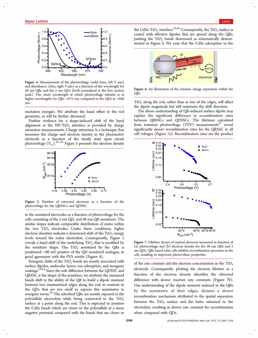
explain the significant difference in recombination ratesbetween QRSSCs and QDSSCs. The lifetimes calculatedfrom transient photovoltage (TPV) measurements67 revealsignificantly slower recombination rates for the QRSSC in allcell voltages (Figure 7a). Recombination rates are the product
of the rate constant and the electron concentration in the TiO2
electrode. Consequently, plotting the electron lifetime as afunction of the electron density identifies the observeddifference with slower reaction rate constants (Figure 7b).Our understanding of the dipole moment induced in the QRsby the asymmetry of their edges, dictates a slowerrecombination mechanism attributed to the spatial separationbetween the TiO2 surface and the holes extracted to theelectrolyte, resulting in slower rate constant for recombinationwhen compared with QDs.
Figure 4. Measurement of the photovoltage (solid lines, left Y axis)and absorbance (dots, right Y-axis) as a function of the wavelength for40 nm QRs and the 5 nm QDs (both normalized at the first excitonpeak). The onset wavelength at which photovoltage initiates is athigher wavelengths for QRs ∼675 nm, compared to the QDs at ∼640nm.
Figure 5. Number of extracted electrons as a function of thephotovoltage for the QRSSCs and QDSSC.
Figure 6. An illustration of the intrinsic charge separation within theQRs.
Figure 7. Lifetime decays of excited electrons measured as function of(a) photovoltage and (b) electron density for the 40 nm QRs and 5nm QDs. QRs based solar cells inhibits recombination processes in thecell, resulting in improved photovoltaic properties.
Nano Letters Letter
dx.doi.org/10.1021/nl300356e | Nano Lett. 2012, 12, 2095−21002098
In summary, QRs and QDs sensitized solar cells werefabricated using EPD. The cells were characterized using photovoltage spectroscopy, charge extraction, and transient photo-voltage measurements all leading to a common understandingregarding a functional difference between QRs and QDs assensitizers. The cell geometry in which the CdSe sensitizer ispositioned at the TiO2 electrode/electrolyte interface mayinduce asymmetry for the QRs that develop a field between theedge connected to the TiO2 and the edge exposed to theelectrolyte, which is in contrast to QDs that are too small toexpress this asymmetry in energetic terms. Consequently, theTiO2 bands are shifted positively while hole extraction occurs ata distance from the TiO2, both leading to higher injection fluxand slower recombination. The results show the prospect ofshifting from QDs to QRs sensitizers in photoelectrochemicalsolar cells. The best performance was observed for the 40 × 5nm QRs based solar cell, reaching 2.7% efficiency at 1 Sun,which is one of the higher efficiencies reported for ex situQPSSCs. Even though the configuration of the mesoporous-TiO2 is not optimal for QRs due to the lower coverage, thecalculated efficiency per particle was higher for QRs comparedto QDs. Therefore, QRs offer new opportunities for theimprovement of solar cells based on nanoparticles.
■ ASSOCIATED CONTENT*S Supporting InformationNPs synthesis method, experimental setup, additional absorb-ance measurements, images of the electrodes, and wetting anglemeasurements are available. This material is available free ofcharge via the Internet at http://pubs.acs.org.
Author Contributions§Equally contributed to this paper.
NotesThe authors declare no competing financial interest.
■ ACKNOWLEDGMENTSWe wish to thank Dr. Yafit Fleger, Yorai Amit, and Amit Sitt fortheir contributions. U.B. acknowledges the support of theWolfson foundation initiative in alternative energy and theAlfred & Erica Larisch memorial chair in solar energy. A.Z.acknowledges financial support within the Israel sciencefoundation, Bikura program. M.S. thanks the “ConvergingTechnologies” program.
■ REFERENCES(1) Zaban, A.; Micic, O. I.; Gregg, B. A.; Nozik, A. J. Langmuir 1998,14 (12), 3153−3156.(2) Nozik, A. J. Physica E 2002, 14 (1−2), 115−120.(3) Luther, J. M.; Law, M.; Beard, M. C.; Song, Q.; Reese, M. O.;Ellingson, R. J.; Nozik, A. J. Nano Lett. 2008, 8 (10), 3488−3492.(4) Hodes, G. Nature 1980, 285 (5759), 29−30.(5) Hodes, G.; Manassen, J.; Cahen, D. J. Electrochem. Soc. 1980, 127(3), 544−549.(6) Nicolau, Y. F. Appl. Surf. Sci. 1985, 22−3 (May), 1061−1074.(7) O’Regan, B.; Gratzel, M. Nature 1991, 353 (6346), 737−740.(8) Yang, Z.; Chen, C.-Y.; Roy, P.; Chang, H.-T. Chem. Commun.2011, 47 (34), 9561−9571.
(9) Im, S. H.; Lim, C.-S.; Chang, J. A.; Lee, Y. H.; Maiti, N.; Kim, H.-J.; Nazeeruddin, M. K.; Gratzel, M.; Seok, S. I. Nano Lett. 2011, 11(11), 4789−4793.(10) Santra, P. K.; Kamat, P. V. J. Am. Chem. Soc. 2012, 134 (5),2508−2511.(11) Plass, R.; Pelet, S.; Krueger, J.; Gratzel, M.; Bach, U. J. Phys.Chem. B 2002, 106 (31), 7578−7580.(12) Niitsoo, O.; Sarkar, S. K.; Pejoux, C.; Ruhle, S.; Cahen, D.;Hodes, G. J. Photochem. Photobiol., A 2006, 181 (2−3), 306−313.(13) Shalom, M.; Dor, S.; Ruuhle, S.; Grinis, L.; Zaban, A. J. Phys.Chem. C 2009, 113 (9), 3895−3898.(14) Gonzalez-Pedro, V.; Xu, X.; Mora-Sero, I. n.; Bisquert, J. ACSNano 2010, 4 (10), 5783−5790.(15) Mora-Sero, I. n.; Bisquert, J. J. Phys. Chem. Lett. 2010, 1 (20),3046−3052.(16) Ruhle, S.; Shalom, M.; Zaban, A. ChemPhysChem 2010, 11 (11),2290−2304.(17) Shalom, M.; Hod, I.; Tachan, Z.; Buhbut, S.; Tirosh, S.; Zaban,A. Energy Environ. Sci. 2011, 4 (5), 1874−1878.(18) Boix, P. P.; Lee, Y. H.; Fabregat-Santiago, F.; Im, S. H.; Mora-Sero, I.; Bisquert, J.; Seok, S. I. ACS Nano 2012, 6 (1), 873−880.(19) Yu, P. R.; Zhu, K.; Norman, A. G.; Ferrere, S.; Frank, A. J.;Nozik, A. J. J. Phys. Chem. B 2006, 110 (50), 25451−25454.(20) Kamat, P. V. J. Phys. Chem. C 2008, 112 (48), 18737−18753.(21) Ivan, M.-S.; Sixto, G.; Thomas, M.; Francisco, F.-S.; Teresa, L.-V.; Roberto, G.; Juan, B. Nanotechnology 2008, 19 (42), 424007.(22) Guijarro, N.; Lana-Villarreal, T.; Mora-Sero, I.; Bisquert, J.;Gomez, R. J. Phys. Chem. C 2009, 113 (10), 4208−4214.(23) Salant, A.; Shalom, M.; Hod, I.; Faust, A.; Zaban, A.; Banin, U.ACS Nano 2010, 4 (10), 5962−5968.(24) Peng, Z. A.; Peng, X. J. Am. Chem. Soc. 2002, 124 (13), 3343−3353.(25) Peng, X. G.; Manna, L.; Yang, W. D.; Wickham, J.; Scher, E.;Kadavanich, A.; Alivisatos, A. P. Nature 2000, 404 (6773), 59−61.(26) Kanaras, A. G.; Sonnichsen, C.; Liu, H.; Alivisatos, A. P. NanoLett. 2005, 5 (11), 2164−2167.(27) Sitt, A.; Salant, A.; Menagen, G.; Banin, U. Nano Lett. 2011, 11(5), 2054−2060.(28) Luther, J. M.; Zheng, H.; Sadtler, B.; Alivisatos, A. P. J. Am.Chem. Soc. 2009, 131 (46), 16851−16857.(29) Krishnan, R.; Hahn, M. A.; Yu, Z.; Silcox, J.; Fauchet, P. M.;Krauss, T. D. Phys. Rev. Lett. 2004, 92 (21), 216803.(30) Smyder, J. A.; Krauss, T. D. Mater. Today 2011, 14 (9), 382−387.(31) Greenham, N. C.; Peng, X.; Alivisatos, A. P. Phys. Rev. B 1996,54 (24), 17628.(32) Ginger, D. S.; Greenham, N. C. Phys. Rev. B 1999, 59 (16),10622.(33) Sun, B. Q.; Marx, E.; Greenham, N. C. Nano Lett. 2003, 3 (7),961−963.(34) Gur, I.; Fromer, N. A.; Chen, C.-P.; Kanaras, A. G.; Alivisatos, A.P. Nano Lett. 2006, 7 (2), 409−414.(35) Rivest, J. B.; Swisher, S. L.; Fong, L.-K.; Zheng, H.; Alivisatos, A.P. ACS Nano 2011, 5 (5), 3811−3816.(36) Katz, D.; Wizansky, T.; Millo, O.; Rothenberg, E.; Mokari, T.;Banin, U. Phys. Rev. Lett. 2002, 89 (8), 086801.(37) Huynh, W. U.; Dittmer, J. J.; Alivisatos, A. P. Science 2002, 295(5564), 2425−2427.(38) Huynh, W. U.; Dittmer, J. J.; Libby, W. C.; Whiting, G. L.;Alivisatos, A. P. Adv. Funct. Mater. 2003, 13 (1), 73−79.(39) Gur, I.; Fromer, N. A.; Geier, M. L.; Alivisatos, A. P. Science2005, 310 (5747), 462−465.(40) Sun, B.; Greenham, N. C. Phys. Chem. Chem. Phys. 2006, 8 (30),3557−3560.(41) Wu, Y.; Wadia, C.; Ma, W.; Sadtler, B.; Alivisatos, A. P. NanoLett. 2008, 8 (8), 2551−2555.(42) Shaviv, E.; Salant, A.; Banin, U. ChemPhysChem 2009, 10 (7),1028−1031.(43) Shabaev, A.; Efros, A. L. Nano Lett. 2004, 4 (10), 1821−1825.
Nano Letters Letter
dx.doi.org/10.1021/nl300356e | Nano Lett. 2012, 12, 2095−21002099
(44) Rothenberg, E.; Kazes, M.; Shaviv, E.; Banin, U. Nano Lett.2005, 5 (8), 1581−1586.(45) Krahne, R.; Morello, G.; Figuerola, A.; George, C.; Deka, S.;Manna, L. Phys. Rep. 2011, 501 (3−5), 75−221.(46) Islam, M. A.; Xia, Y. Q.; Telesca, D. A.; Steigerwald, M. L.;Herman, I. P. Chem. Mater. 2004, 16 (1), 49−54.(47) Jia, S.; Banerjee, S.; Herman, I. P. J. Phys. Chem. C 2008, 112(1), 162−171.(48) Ryan, K. M.; Mastroianni, A.; Stancil, K. A.; Liu, H.; Alivisatos,A. P. Nano Lett. 2006, 6 (7), 1479−1482.(49) Ahmed, S.; Ryan, K. M. Chem. Commun. 2009, No. 42, 6421−6423.(50) Smith, N. J.; Emmett, K. J.; Rosenthal, S. J. Appl. Phys. Lett.2008, 93 (4), 043504.(51) Brown, P.; Kamat, P. V. J. Am. Chem. Soc. 2008, 130 (28),8890−8891.(52) Farrow, B.; Kamat, P. V. J. Am. Chem. Soc. 2009, 131 (31),11124−11131.(53) Murray, C. B.; Norris, D. J.; Bawendi, M. G. J. Am. Chem. Soc.1993, 115 (19), 8706−8715.(54) Peng, X. G.; Wickham, J.; Alivisatos, A. P. J. Am. Chem. Soc.1998, 120 (21), 5343−5344.(55) Robel, I.; Subramanian, V.; Kuno, M.; Kamat, P. V. J. Am. Chem.Soc. 2006, 128 (7), 2385−2393.(56) Shen, Q.; Kobayashi, J.; Diguna, L. J.; Toyoda, T. J. Appl. Phys.2008, 103 (8), 084304−5.(57) Guijarro, N.; Campina, J. M.; Shen, Q.; Toyoda, T.; Lana-Villarreal, T.; Gomez, R. Phys. Chem. Chem. Phys. 2011, 13 (25),12024−12032.(58) Shalom, M.; Ruhle, S.; Hod, I.; Yahav, S.; Zaban, A. J. Am. Chem.Soc. 2009, 131 (29), 9876−9877.(59) Duffy, N. W.; Peter, L. M.; Rajapakse, R. M. G.; Wijayantha, K.G. U. Electrochem. Commun. 2000, 2 (9), 658−662.(60) Bailes, M.; Cameron, P. J.; Lobato, K.; Peter, L. M. J. Phys.Chem. B 2005, 109 (32), 15429−15435.(61) Peter, L. M. J. Phys. Chem. C 2007, 111 (18), 6601−6612.(62) Sanchez-Diaz, A.; Izquierdo, M.; Filippone, S.; Martin, N.;Palomares, E. Adv. Funct. Mater. 2010, 20 (16), 2695−2700.(63) Ruhle, S.; Greenshtein, M.; Chen, S. G.; Merson, A.; Pizem, H.;Sukenik, C. S.; Cahen, D.; Zaban, A. J. Phys. Chem. B 2005, 109 (40),18907−18913.(64) Grinis, L.; Kotlyar, S.; Ruehle, S.; Grinblat, J.; Zaban, A. Adv.Funct. Mater. 2010, 20 (2), 282−288.(65) Hodes, G. J. Phys. Chem. C 2008, 112 (46), 17778−17787.(66) Greenwald, S.; Ruhle, S.; Shalom, M.; Yahav, S.; Zaban, A. Phys.Chem. Chem. Phys. 2011, 13 (43), 19302−19306.(67) Bisquert, J.; Zaban, A.; Greenshtein, M.; Mora-Sero, I. J. Am.Chem. Soc. 2004, 126 (41), 13550−13559.
Nano Letters Letter
dx.doi.org/10.1021/nl300356e | Nano Lett. 2012, 12, 2095−21002100