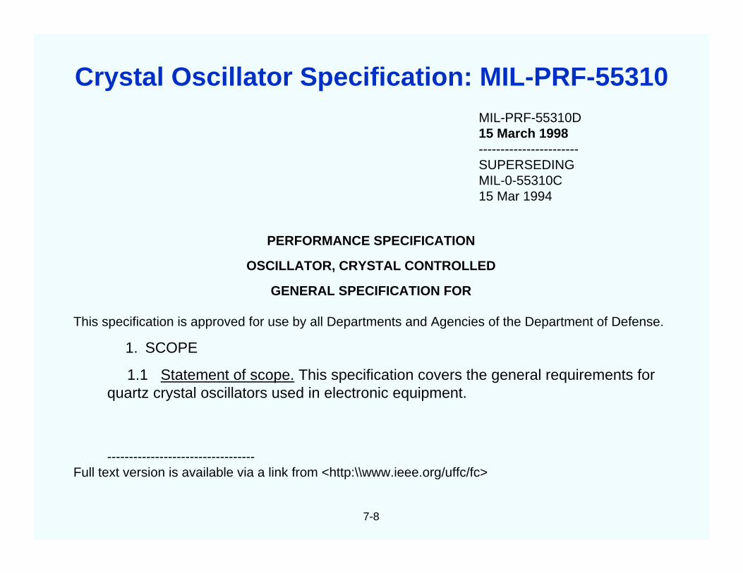
SLCET-TR-88-1 (Rev.8.4.3) AD-A328861 (revised) For Frequency Control and Timing Applications A Tutorial John R. Vig U.S. Army Communications-Electronics Command Attn: AMSEL-RD-C2-PT Fort Monmouth, NJ 07703, USA [email protected]January 2001 Approved for public release. Distribution is unlimited. QUARTZ CRYSTAL RESONATORS AND OSCILLATORS
Transcript
SLCET-TR-88-1 (Rev.8.4.3) AD-A328861 (revised)
For Frequency Control and Timing Applications
A Tutorial
John R. VigU.S. Army Communications-Electronics Command
Approved for public release.Distribution is unlimited.
QUARTZ CRYSTALRESONATORS AND OSCILLATORS
NOTICES
The findings in this report are not to be construed as anofficial Department of the Army position, unless sodesignated by other authorized documents.
The citation of trade names and names of manufacturersin this report is not to be construed as official Governmentendorsement or consent or approval of commercialproducts or services referenced herein.
Disclaimer
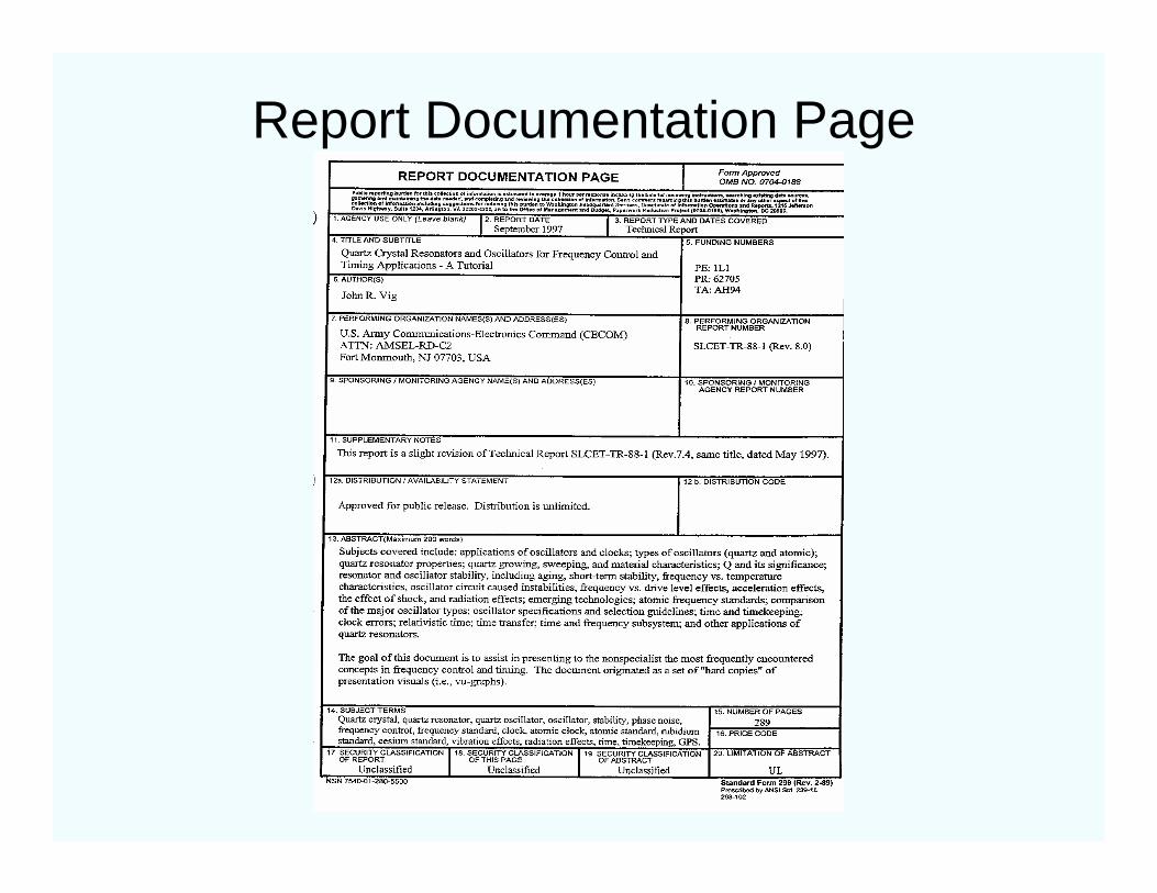
Report Documentation Page
iii
Table of Contents
Preface………………………………..……………………….. v
1. Applications and Requirements………………………. 1
2. Quartz Crystal Oscillators………………………………. 2
3. Quartz Crystal Resonators……………………………… 3
4. Oscillator Stability………………………………………… 4
5. Quartz Material Properties……………………………... 5
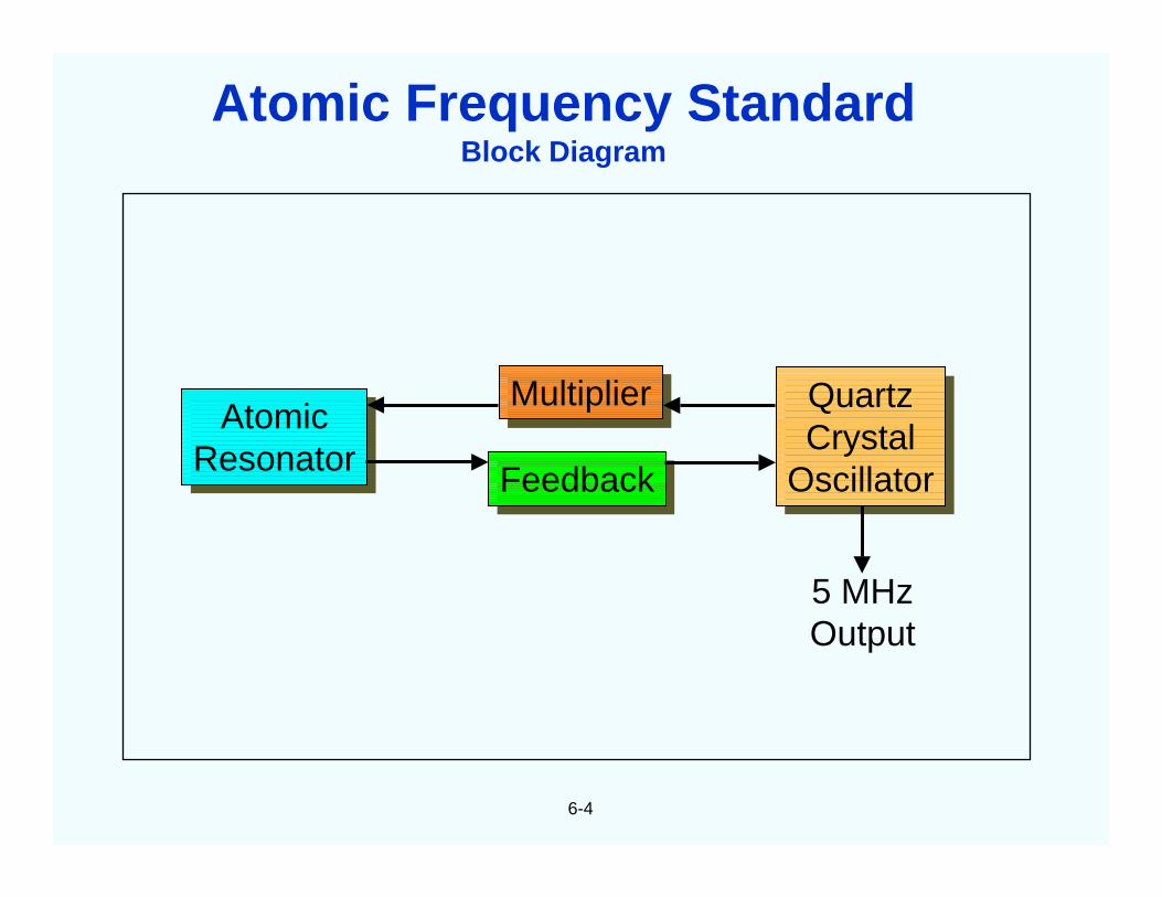
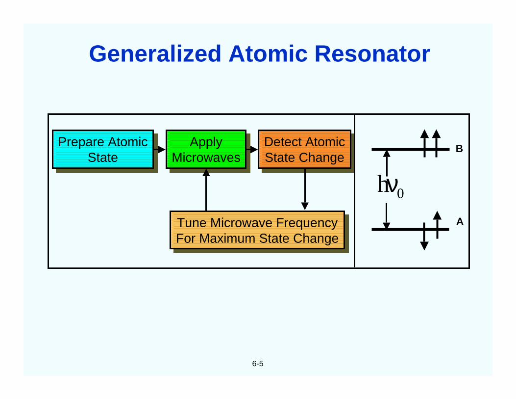
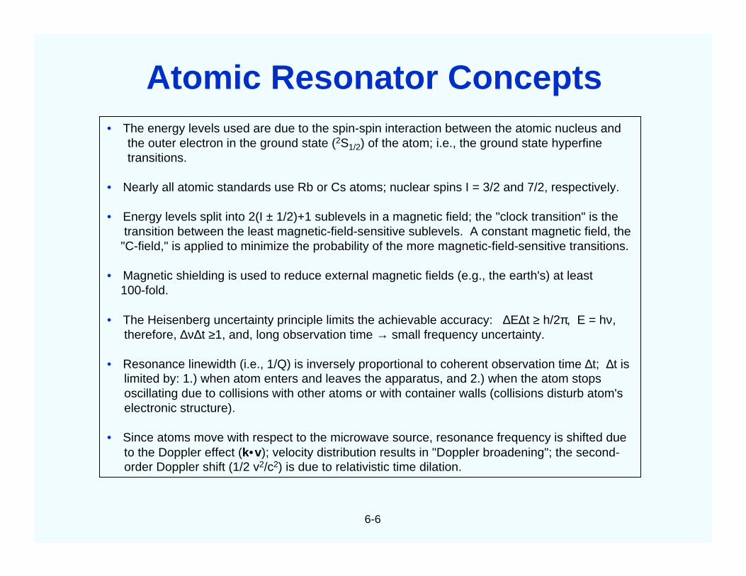
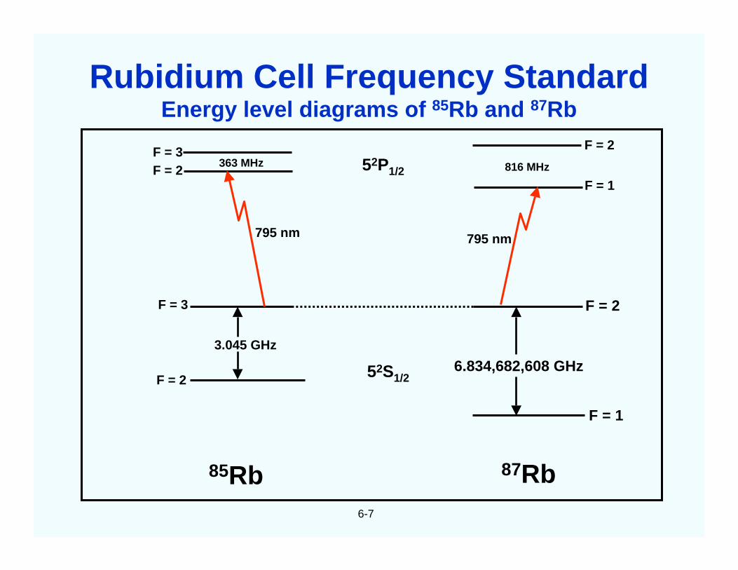
6. Atomic Frequency Standards…………………………… 6
7. Oscillator Comparison and Specification…………….. 7
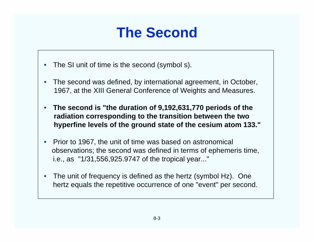
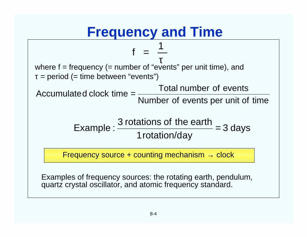
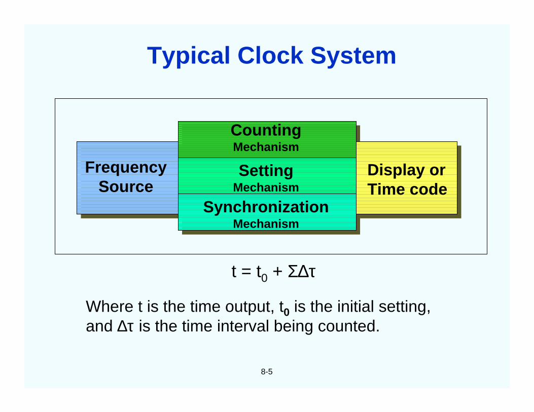
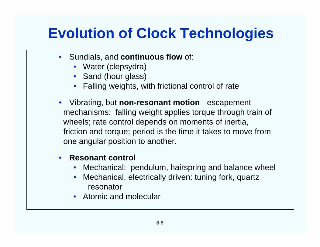
8. Time and Timekeeping…………………………………. 8
9. Related Devices and Applications……………………… 9
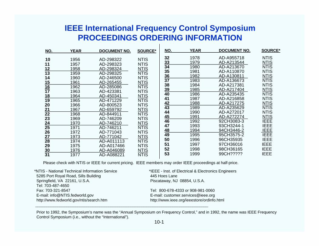
10. FCS Proceedings Ordering, Website, and Index………….. 10
“Everything should be made as simple aspossible - but not simpler,” said Einstein. Themain goal of this “tutorial” is to assist withpresenting the most frequently encounteredconcepts in frequency control and timing, assimply as possible.
I have often been called upon to briefvisitors, management, and potential users ofprecision oscillators, and have also beeninvited to present seminars, tutorials, andreview papers before university, IEEE, andother professional groups. In the beginning, Ispent a great deal of time preparing thesepresentations. Much of the time was spent onpreparing the slides. As I accumulated moreand more slides, it became easier and easierto prepare successive presentations.
I was frequently asked for “hard-copies”of the slides, so I started organizing, addingsome text, and filling the gaps in the slidecollection. As the collection grew, I beganreceiving favorable comments and requestsfor additional copies. Apparently, others, too,found this collection to be useful. Eventually, Iassembled this document, the “Tutorial”.
This is a work in progress. I plan toinclude new material, including additionalnotes. Comments, corrections, andsuggestions for future revisions will bewelcome.
John R. Vig
iv
Preface
Why This Tutorial?
v
In the PowerPoint version of this document, notes and referencescan be found in the “Notes” of most of the pages. To view the notes,use the “Notes Page View” icon (near the lower left corner of thescreen), or select “Notes Page” in the View menu. In PowerPoint2000 (and, presumably, later versions), the notes also appear in the“Normal view”.
To print a page so that it includes the notes, select Print in theFile menu, and, near the bottom, at “Print what:,” select “NotesPages”.
The HTML version can be viewed with a web browser (bestviewed at 1024 x 768 screen size). The notes then appear in thelower pane on the right.
Many of the references are to IEEE publications that are availableonline in the IEEE UFFC-S digital archive, www.ieee-uffc.org/archiveor in IEEE Xplore, http://www.ieee.org/ieeexplore .
Notes and References
1
CHAPTER 1Applications and Requirements
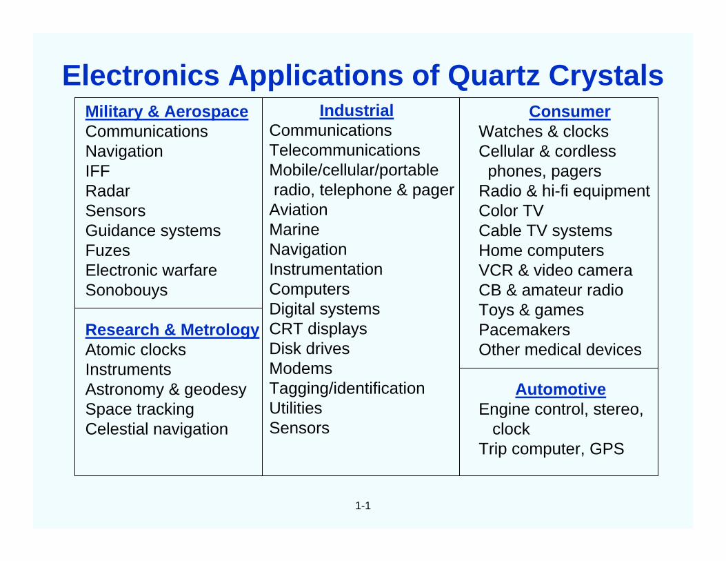
Military & AerospaceCommunicationsNavigationIFFRadarSensorsGuidance systemsFuzesElectronic warfareSonobouys
Research & MetrologyAtomic clocksInstrumentsAstronomy & geodesySpace trackingCelestial navigation
Radio & hi-fi equipmentColor TVCable TV systemsHome computersVCR & video cameraCB & amateur radioToys & gamesPacemakersOther medical devices
AutomotiveEngine control, stereo,
clockTrip computer, GPS
1-1
Electronics Applications of Quartz Crystals
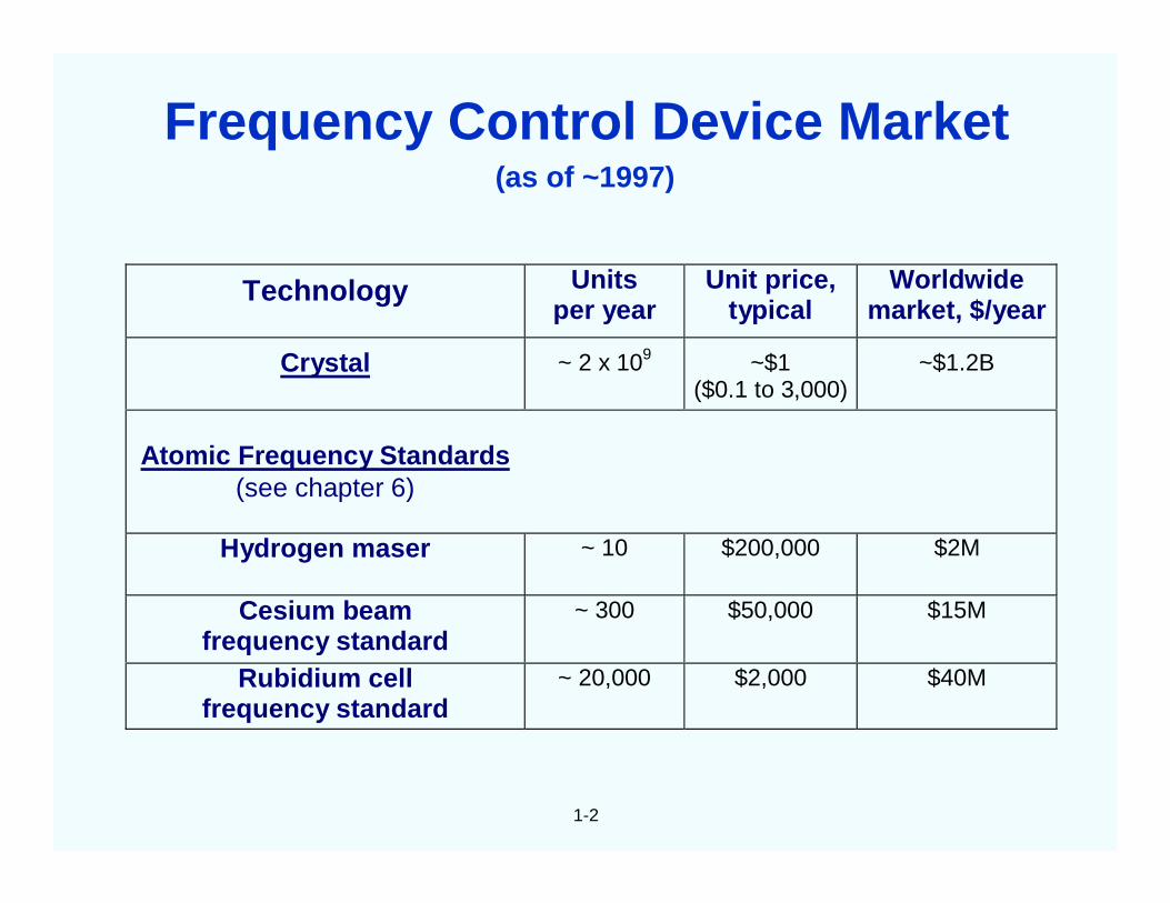
1-2
(as of ~1997)
Technology Unitsper year
Unit price,typical
Worldwidemarket, $/year
Crystal ~ 2 x 10⁹ ~$1($0.1 to 3,000)
~$1.2B
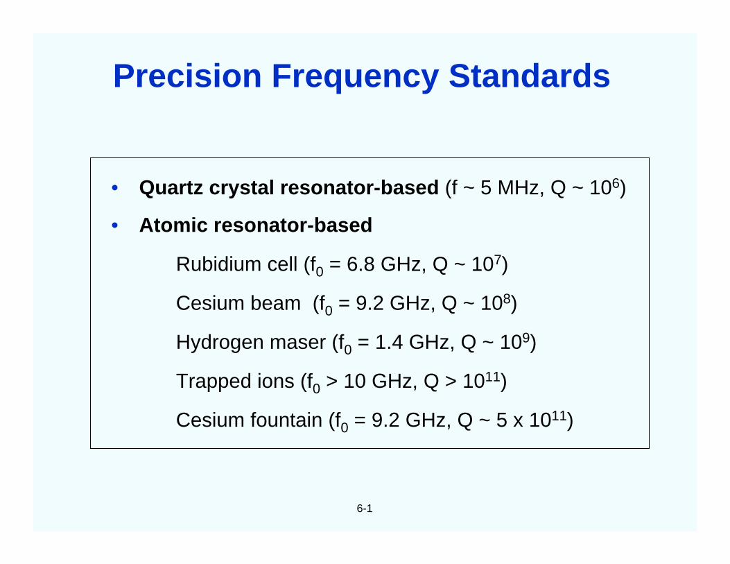
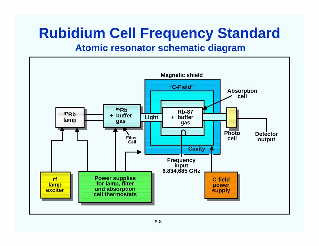
Atomic Frequency Standards(see chapter 6)
Hydrogen maser ~ 10 $200,000 $2M
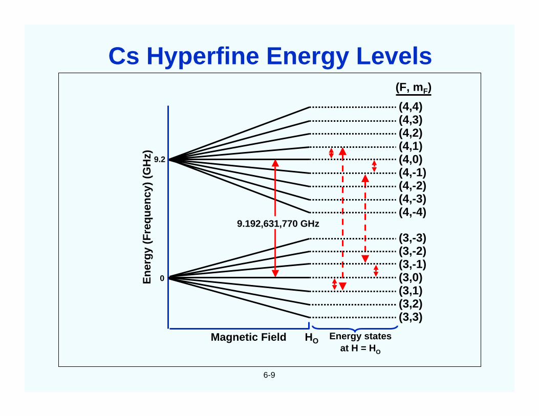
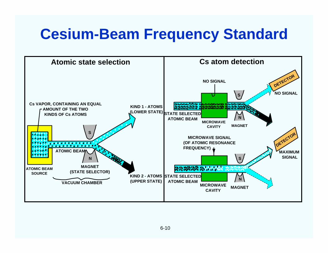
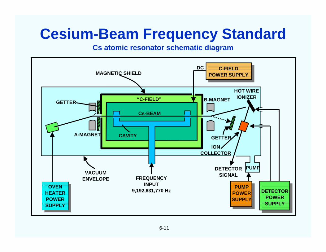
Cesium beamfrequency standard
~ 300 $50,000 $15M
Rubidium cellfrequency standard
~ 20,000 $2,000 $40M
Frequency Control Device Market
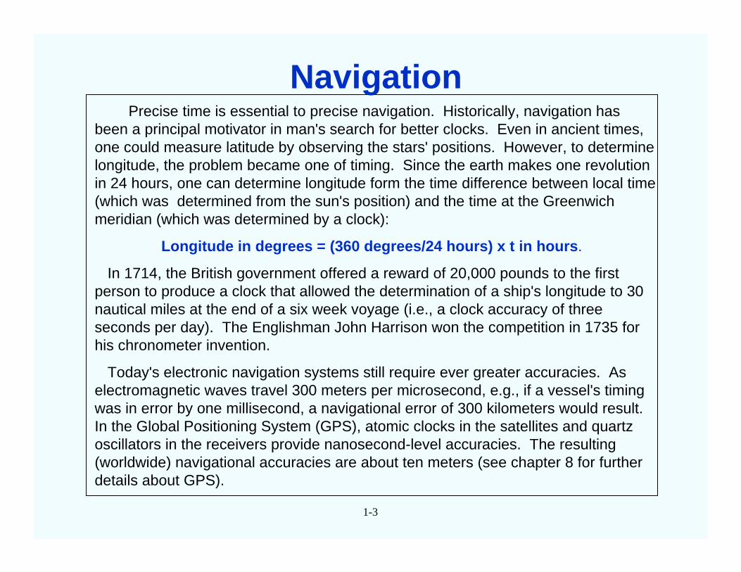
Precise time is essential to precise navigation. Historically, navigation hasbeen a principal motivator in man's search for better clocks. Even in ancient times,one could measure latitude by observing the stars' positions. However, to determinelongitude, the problem became one of timing. Since the earth makes one revolutionin 24 hours, one can determine longitude form the time difference between local time(which was determined from the sun's position) and the time at the Greenwichmeridian (which was determined by a clock):
Longitude in degrees = (360 degrees/24 hours) x t in hours.
In 1714, the British government offered a reward of 20,000 pounds to the firstperson to produce a clock that allowed the determination of a ship's longitude to 30nautical miles at the end of a six week voyage (i.e., a clock accuracy of threeseconds per day). The Englishman John Harrison won the competition in 1735 forhis chronometer invention.
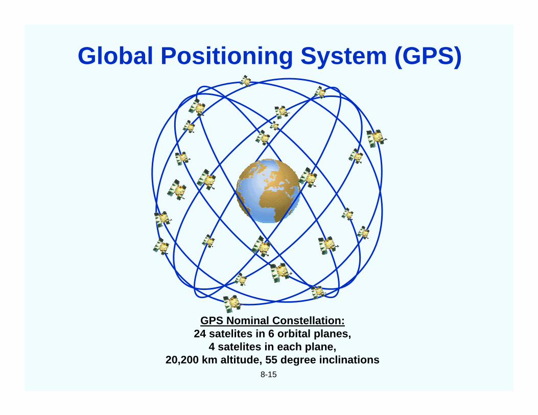
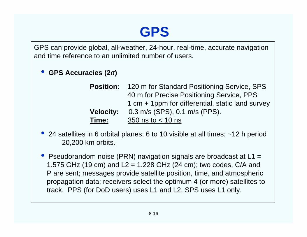
Today's electronic navigation systems still require ever greater accuracies. Aselectromagnetic waves travel 300 meters per microsecond, e.g., if a vessel's timingwas in error by one millisecond, a navigational error of 300 kilometers would result.In the Global Positioning System (GPS), atomic clocks in the satellites and quartzoscillators in the receivers provide nanosecond-level accuracies. The resulting(worldwide) navigational accuracies are about ten meters (see chapter 8 for furtherdetails about GPS).
1-3
Navigation
1-4
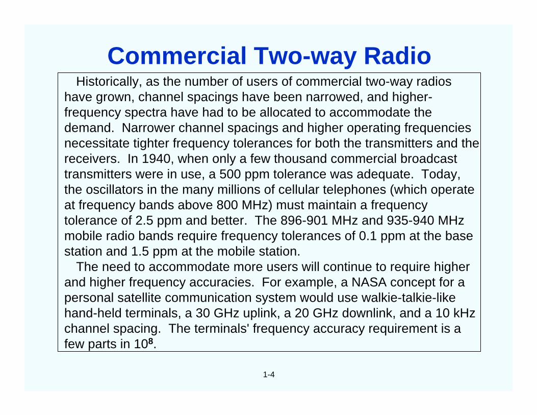
Historically, as the number of users of commercial two-way radioshave grown, channel spacings have been narrowed, and higher-frequency spectra have had to be allocated to accommodate thedemand. Narrower channel spacings and higher operating frequenciesnecessitate tighter frequency tolerances for both the transmitters and thereceivers. In 1940, when only a few thousand commercial broadcasttransmitters were in use, a 500 ppm tolerance was adequate. Today,the oscillators in the many millions of cellular telephones (which operateat frequency bands above 800 MHz) must maintain a frequencytolerance of 2.5 ppm and better. The 896-901 MHz and 935-940 MHzmobile radio bands require frequency tolerances of 0.1 ppm at the basestation and 1.5 ppm at the mobile station.
The need to accommodate more users will continue to require higherand higher frequency accuracies. For example, a NASA concept for apersonal satellite communication system would use walkie-talkie-likehand-held terminals, a 30 GHz uplink, a 20 GHz downlink, and a 10 kHzchannel spacing. The terminals' frequency accuracy requirement is afew parts in 108.
Commercial Two-way Radio
1-5
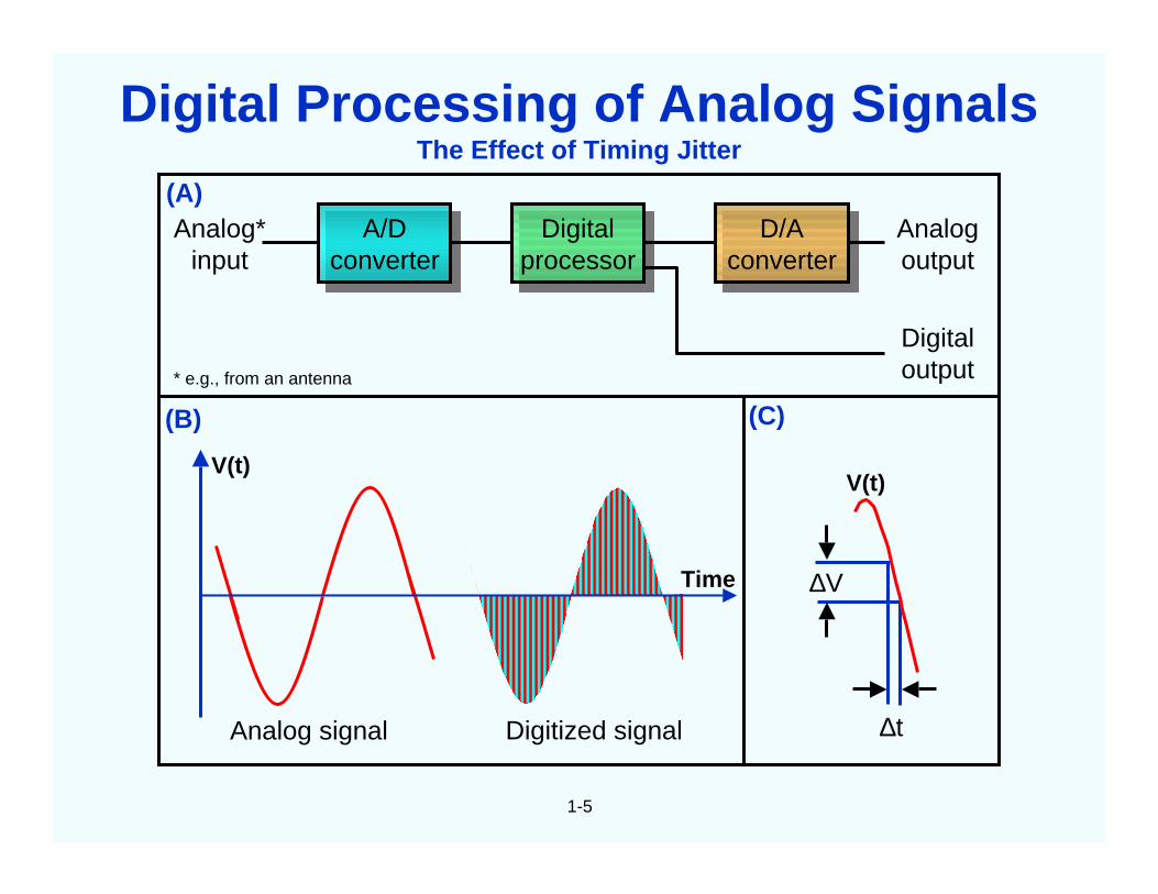
The Effect of Timing Jitter
A/Dconverter
A/Dconverter
Digitalprocessor
Digitalprocessor
D/Aconverter
D/Aconverter
Analog*input
Analogoutput
Digitaloutput
Digitized signal
∆V
∆t
Time
Analog signal
(A)
(B) (C)
V(t)V(t)
* e.g., from an antenna
Digital Processing of Analog Signals
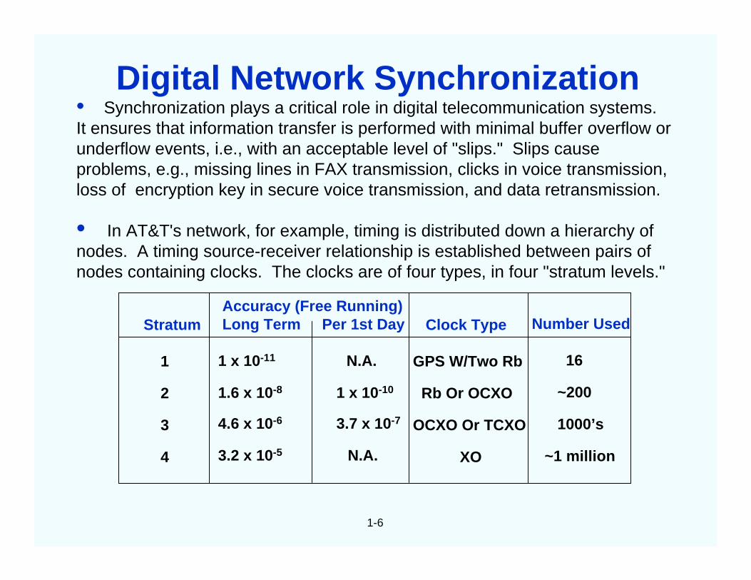
• Synchronization plays a critical role in digital telecommunication systems.It ensures that information transfer is performed with minimal buffer overflow orunderflow events, i.e., with an acceptable level of "slips." Slips causeproblems, e.g., missing lines in FAX transmission, clicks in voice transmission,loss of encryption key in secure voice transmission, and data retransmission.
• In AT&T's network, for example, timing is distributed down a hierarchy ofnodes. A timing source-receiver relationship is established between pairs ofnodes containing clocks. The clocks are of four types, in four "stratum levels."
1-6
Stratum
1
2
3
4
Accuracy (Free Running)Long Term Per 1st Day
1 x 10-11 N.A.
1.6 x 10⁻⁸ 1 x 10⁻¹⁰
4.6 x 10⁻⁶ 3.7 x 10⁻⁷
3.2 x 10⁻⁵ N.A.
Clock Type
GPS W/Two Rb
Rb Or OCXO
OCXO Or TCXO
XO
Number Used
16
~200
1000’s
~1 million
Digital Network Synchronization
1-7
The phase noise of oscillators can lead to erroneous detection ofphase transitions, i.e., to bit errors, when phase shift keyed (PSK) digitalmodulation is used. In digital communications, for example, where8-phase PSK is used, the maximum phase tolerance is ±22.5o, of which±7.5o is the typical allowable carrier noise contribution. Due to thestatistical nature of phase deviations, if the RMS phase deviation is 1.5o,for example, the probability of exceeding the ±7.5o phase deviation is6 X 10-7, which can result in a bit error rate that is significant in someapplications.
Shock and vibration can produce large phase deviations even in"low noise" oscillators. Moreover, when the frequency of an oscillator ismultiplied by N, the phase deviations are also multiplied by N. Forexample, a phase deviation of 10-3 radian at 10 MHz becomes 1 radianat 10 GHz. Such large phase excursions can be catastrophic to theperformance of systems, e.g., of those which rely on phase locked loops(PLL) or phase shift keying (PSK). Low noise, acceleration insensitiveoscillators are essential in such applications.
Phase Noise in PLL and PSK Systems
1-8
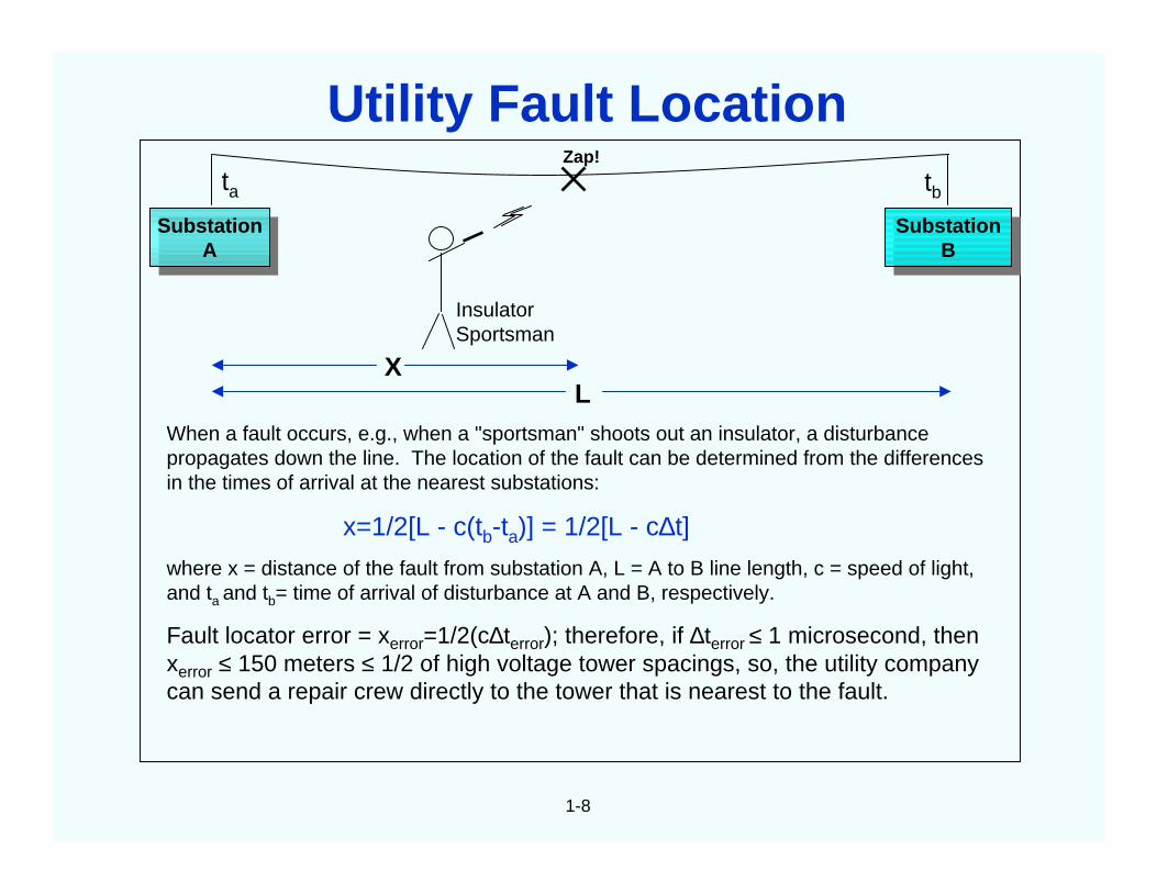
When a fault occurs, e.g., when a "sportsman" shoots out an insulator, a disturbancepropagates down the line. The location of the fault can be determined from the differencesin the times of arrival at the nearest substations:
x=1/2[L - c(tb-ta)] = 1/2[L - c∆t]
where x = distance of the fault from substation A, L = A to B line length, c = speed of light,and ta and tb= time of arrival of disturbance at A and B, respectively.
Fault locator error = xerror=1/2(c∆terror); therefore, if ∆terror ≤ 1 microsecond, thenxerror ≤ 150 meters ≤ 1/2 of high voltage tower spacings, so, the utility companycan send a repair crew directly to the tower that is nearest to the fault.
SubstationA
SubstationA
SubstationB
SubstationB
InsulatorSportsman
XL
Zap!
ta tb
Utility Fault Location
1-9
θ(t)
∆θ
Wavefront
Meanwavelength λ
∆θ
∆t
LocalTime &
FrequencyStandard
LocalTime &
FrequencyStandard
Schematic of VBLITechnique
Microwavemixer
RecorderRecorder
MicrowavemixerLocal
Time &FrequencyStandard
LocalTime &
FrequencyStandard
RecorderRecorder
Correlationand
Integration
Correlationand
Integration
Data tapeData tape
θ
∆∆θ
Lsintc=
Amplitude InterferenceFringes
θsinλ/L ( ) Angleτθ
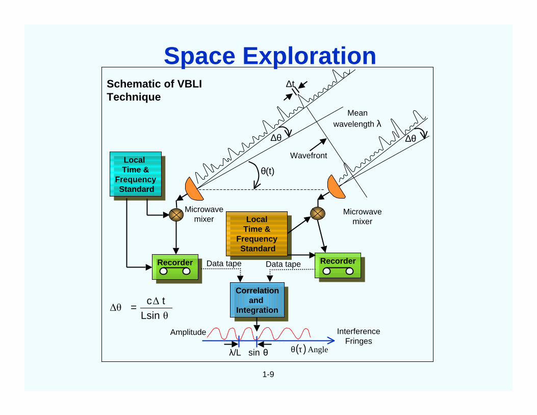
Space Exploration
1-10
Military needs are a prime driver of frequency controltechnology. Modern military systems requireoscillators/clocks that are:
• Stable over a wide range of parameters (time,temperature, acceleration, radiation, etc.)
• Low noise
• Low power
• Small size
• Fast warmup
• Low life-cycle cost
Military Requirements
1-11
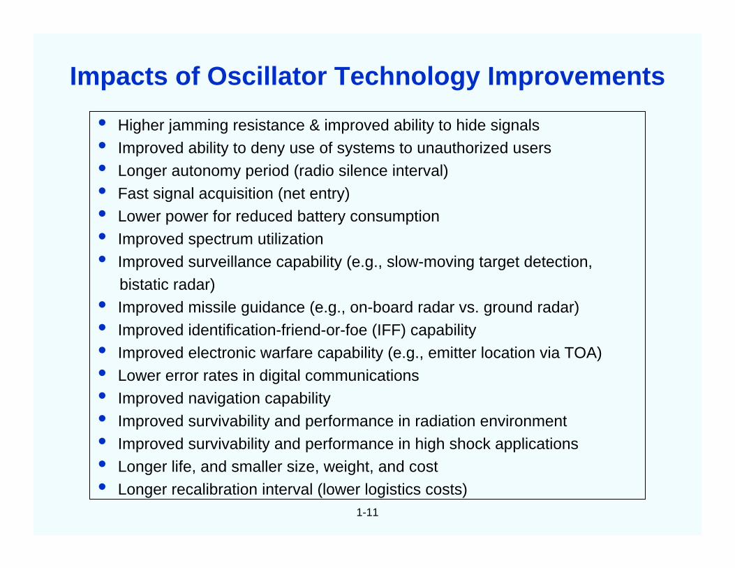
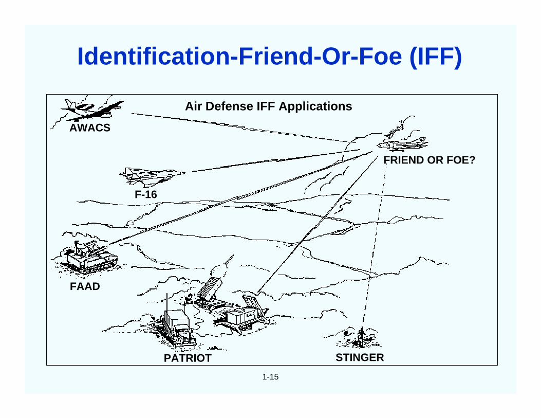
• Higher jamming resistance & improved ability to hide signals• Improved ability to deny use of systems to unauthorized users• Longer autonomy period (radio silence interval)• Fast signal acquisition (net entry)• Lower power for reduced battery consumption• Improved spectrum utilization• Improved surveillance capability (e.g., slow-moving target detection,
bistatic radar)• Improved missile guidance (e.g., on-board radar vs. ground radar)• Improved identification-friend-or-foe (IFF) capability• Improved electronic warfare capability (e.g., emitter location via TOA)• Lower error rates in digital communications• Improved navigation capability• Improved survivability and performance in radiation environment• Improved survivability and performance in high shock applications• Longer life, and smaller size, weight, and cost• Longer recalibration interval (lower logistics costs)
Impacts of Oscillator Technology Improvements
1-12
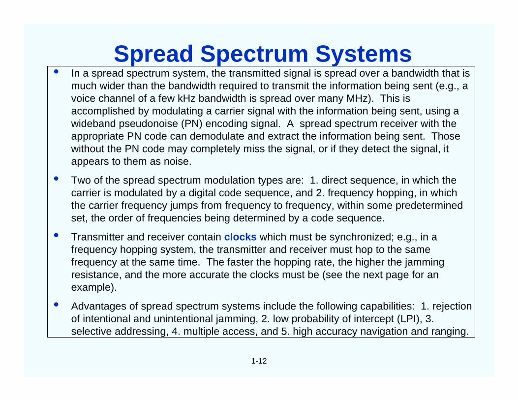
• In a spread spectrum system, the transmitted signal is spread over a bandwidth that ismuch wider than the bandwidth required to transmit the information being sent (e.g., avoice channel of a few kHz bandwidth is spread over many MHz). This isaccomplished by modulating a carrier signal with the information being sent, using awideband pseudonoise (PN) encoding signal. A spread spectrum receiver with theappropriate PN code can demodulate and extract the information being sent. Thosewithout the PN code may completely miss the signal, or if they detect the signal, itappears to them as noise.
• Two of the spread spectrum modulation types are: 1. direct sequence, in which thecarrier is modulated by a digital code sequence, and 2. frequency hopping, in whichthe carrier frequency jumps from frequency to frequency, within some predeterminedset, the order of frequencies being determined by a code sequence.
• Transmitter and receiver contain clocks which must be synchronized; e.g., in afrequency hopping system, the transmitter and receiver must hop to the samefrequency at the same time. The faster the hopping rate, the higher the jammingresistance, and the more accurate the clocks must be (see the next page for anexample).
• Advantages of spread spectrum systems include the following capabilities: 1. rejectionof intentional and unintentional jamming, 2. low probability of intercept (LPI), 3.selective addressing, 4. multiple access, and 5. high accuracy navigation and ranging.
Spread Spectrum Systems
1-13
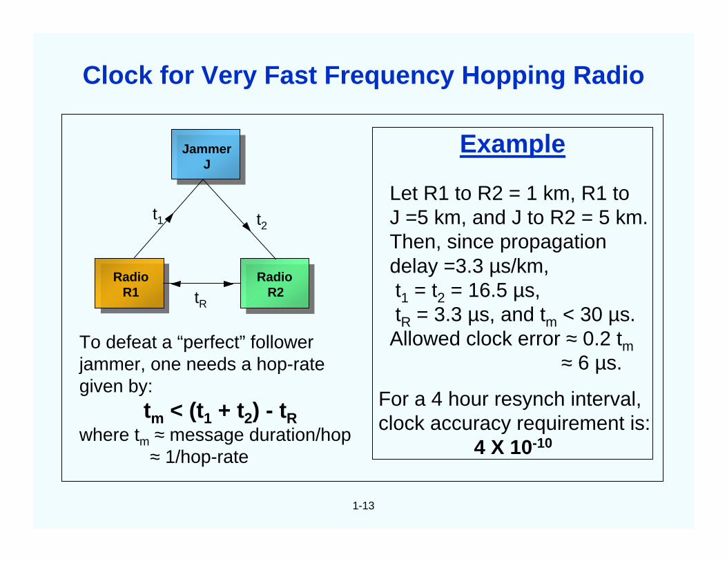
Example
Let R1 to R2 = 1 km, R1 toJ =5 km, and J to R2 = 5 km.Then, since propagationdelay =3.3 µs/km,t1 = t2 = 16.5 µs,tR = 3.3 µs, and tm < 30 µs.
Allowed clock error ≈ 0.2 tm≈ 6 µs.
For a 4 hour resynch interval,clock accuracy requirement is:
4 X 10⁻¹⁰
To defeat a “perfect” followerjammer, one needs a hop-rategiven by:
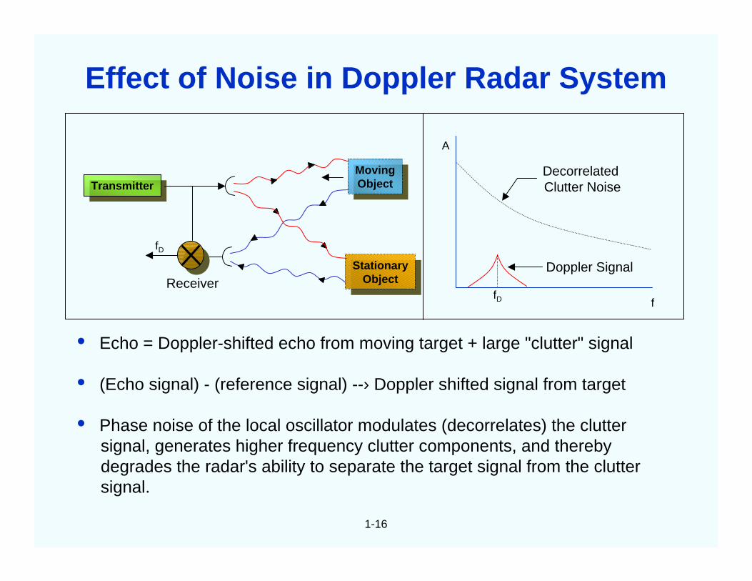
• Echo = Doppler-shifted echo from moving target + large "clutter" signal
• (Echo signal) - (reference signal) --› Doppler shifted signal from target
• Phase noise of the local oscillator modulates (decorrelates) the cluttersignal, generates higher frequency clutter components, and therebydegrades the radar's ability to separate the target signal from the cluttersignal.
TransmitterTransmitter
fD
ReceiverStationary
Object
StationaryObject
MovingObject
MovingObject
ffD
Doppler Signal
DecorrelatedClutter Noise
A
Effect of Noise in Doppler Radar System
1-17
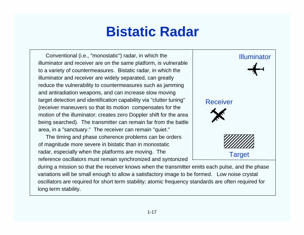
Conventional (i.e., "monostatic") radar, in which theilluminator and receiver are on the same platform, is vulnerableto a variety of countermeasures. Bistatic radar, in which theilluminator and receiver are widely separated, can greatlyreduce the vulnerability to countermeasures such as jammingand antiradiation weapons, and can increase slow movingtarget detection and identification capability via "clutter tuning”(receiver maneuvers so that its motion compensates for themotion of the illuminator; creates zero Doppler shift for the areabeing searched). The transmitter can remain far from the battlearea, in a "sanctuary." The receiver can remain "quiet.”
The timing and phase coherence problems can be ordersof magnitude more severe in bistatic than in monostaticradar, especially when the platforms are moving. Thereference oscillators must remain synchronized and syntonizedduring a mission so that the receiver knows when the transmitter emits each pulse, and the phasevariations will be small enough to allow a satisfactory image to be formed. Low noise crystaloscillators are required for short term stability; atomic frequency standards are often required forlong term stability.
Receiver
Illuminator
Target
Bistatic Radar
1-18
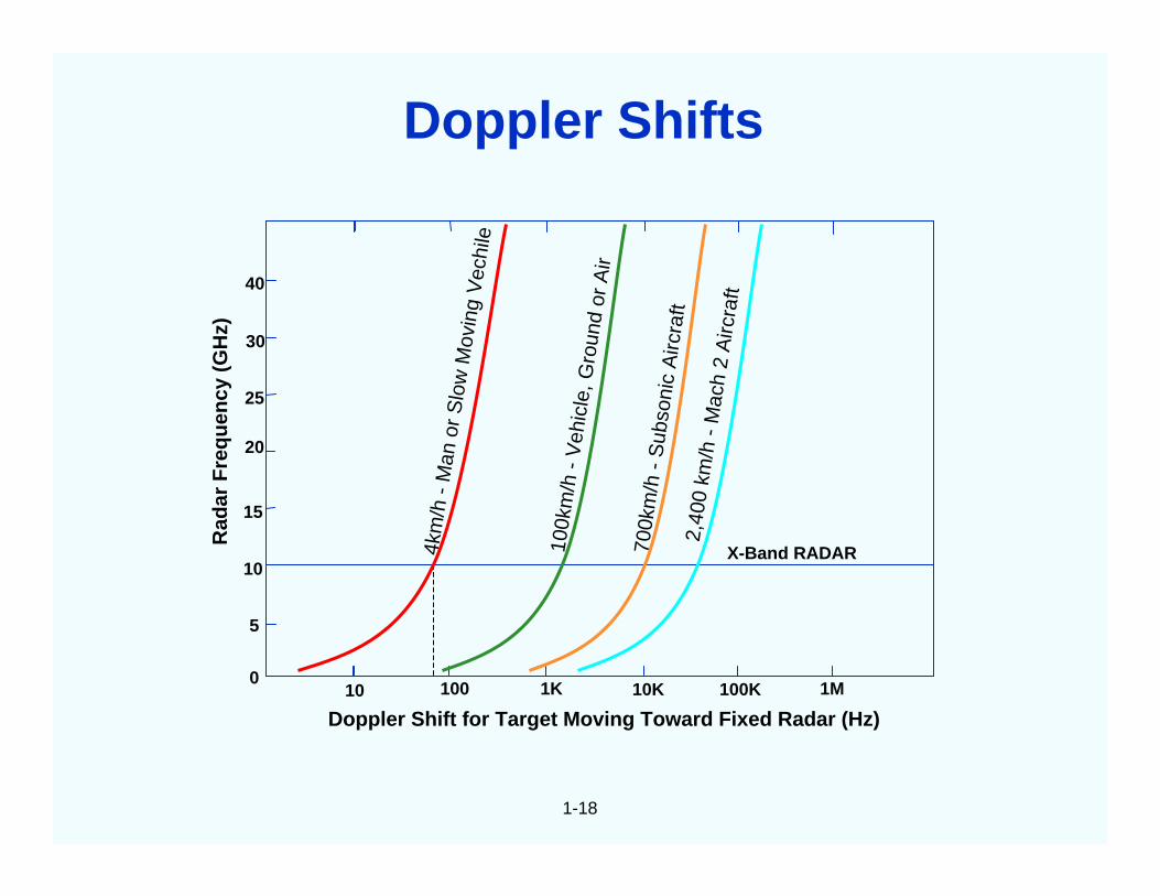
Doppler Shift for Target Moving Toward Fixed Radar (Hz)
5
0
10
15
20
25
30
40
10 100 1K 10K 100K 1M
Rad
arF
r eq
ue n
c y( G
Hz)
4km
/h-
Man
orS
low
Mov
ing
Vec
hile
100k
m/h
-V
ehic
le, G
roun
dor
Air
700k
m/h
-S
ubso
nic
Airc
raft
2,40
0km
/h-
Mac
h2
Airc
raft
X-Band RADAR
Doppler Shifts
2
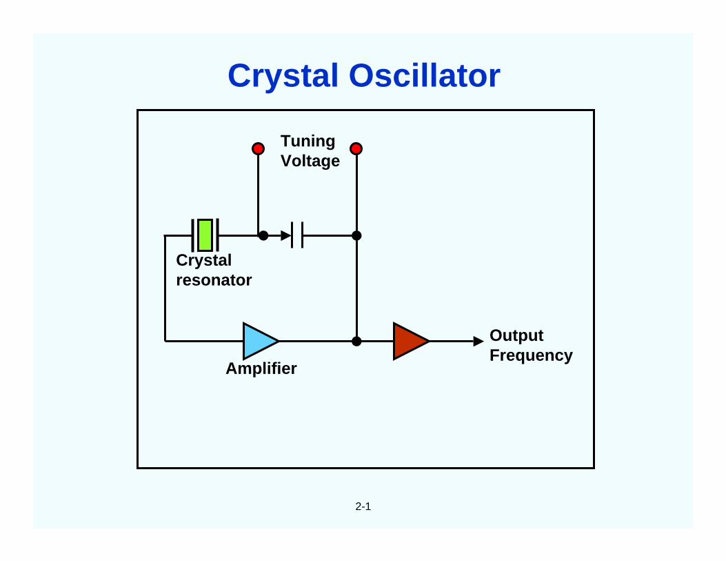
CHAPTER 2Quartz Crystal Oscillators
TuningVoltage
Crystalresonator
Amplifier
OutputFrequency
2-1
Crystal Oscillator
2-2
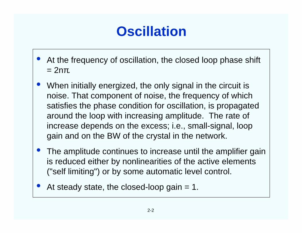
• At the frequency of oscillation, the closed loop phase shift= 2nπ.
• When initially energized, the only signal in the circuit isnoise. That component of noise, the frequency of whichsatisfies the phase condition for oscillation, is propagatedaround the loop with increasing amplitude. The rate ofincrease depends on the excess; i.e., small-signal, loopgain and on the BW of the crystal in the network.
• The amplitude continues to increase until the amplifier gainis reduced either by nonlinearities of the active elements("self limiting") or by some automatic level control.
• At steady state, the closed-loop gain = 1.
Oscillation
2-3
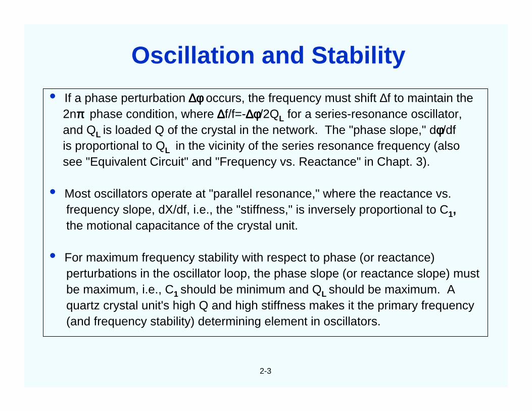
• If a phase perturbation ∆φ∆φ∆φ∆φ occurs, the frequency must shift ∆f to maintain the2nππππ phase condition, where ∆∆∆∆f/f=-∆φ∆φ∆φ∆φ/2QL for a series-resonance oscillator,and QL is loaded Q of the crystal in the network. The "phase slope," dφφφφ/dfis proportional to QL in the vicinity of the series resonance frequency (alsosee "Equivalent Circuit" and "Frequency vs. Reactance" in Chapt. 3).
• Most oscillators operate at "parallel resonance," where the reactance vs.frequency slope, dX/df, i.e., the "stiffness," is inversely proportional to C1,the motional capacitance of the crystal unit.
• For maximum frequency stability with respect to phase (or reactance)perturbations in the oscillator loop, the phase slope (or reactance slope) mustbe maximum, i.e., C1 should be minimum and QL should be maximum. Aquartz crystal unit's high Q and high stiffness makes it the primary frequency(and frequency stability) determining element in oscillators.
Oscillation and Stability
2-4
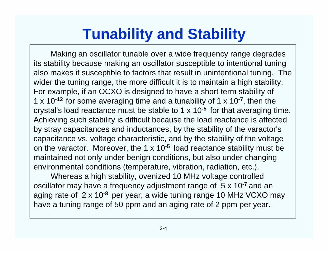
Making an oscillator tunable over a wide frequency range degradesits stability because making an oscillator susceptible to intentional tuningalso makes it susceptible to factors that result in unintentional tuning. Thewider the tuning range, the more difficult it is to maintain a high stability.For example, if an OCXO is designed to have a short term stability of1 x 10-12 for some averaging time and a tunability of 1 x 10⁻⁷, then thecrystal's load reactance must be stable to 1 x 10⁻⁵ for that averaging time.Achieving such stability is difficult because the load reactance is affectedby stray capacitances and inductances, by the stability of the varactor'scapacitance vs. voltage characteristic, and by the stability of the voltageon the varactor. Moreover, the 1 x 10⁻⁵ load reactance stability must bemaintained not only under benign conditions, but also under changingenvironmental conditions (temperature, vibration, radiation, etc.).
Whereas a high stability, ovenized 10 MHz voltage controlledoscillator may have a frequency adjustment range of 5 x 10⁻⁷ and anaging rate of 2 x 10⁻⁸ per year, a wide tuning range 10 MHz VCXO mayhave a tuning range of 50 ppm and an aging rate of 2 ppm per year.
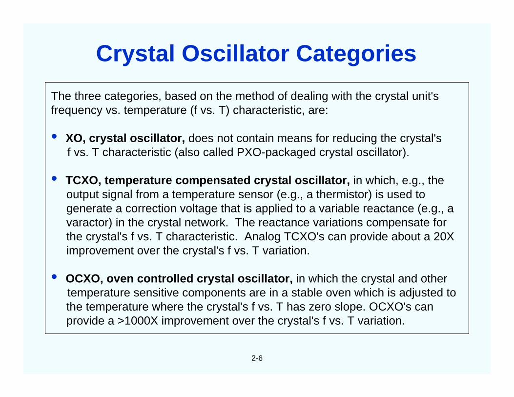
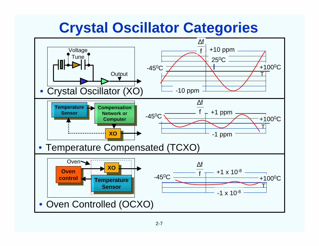
The three categories, based on the method of dealing with the crystal unit'sfrequency vs. temperature (f vs. T) characteristic, are:
• XO, crystal oscillator, does not contain means for reducing the crystal'sf vs. T characteristic (also called PXO-packaged crystal oscillator).
• TCXO, temperature compensated crystal oscillator, in which, e.g., theoutput signal from a temperature sensor (e.g., a thermistor) is used togenerate a correction voltage that is applied to a variable reactance (e.g., avaractor) in the crystal network. The reactance variations compensate forthe crystal's f vs. T characteristic. Analog TCXO's can provide about a 20Ximprovement over the crystal's f vs. T variation.
• OCXO, oven controlled crystal oscillator, in which the crystal and othertemperature sensitive components are in a stable oven which is adjusted tothe temperature where the crystal's f vs. T has zero slope. OCXO's canprovide a >1000X improvement over the crystal's f vs. T variation.
Crystal Oscillator Categories
2-7
TemperatureSensor
TemperatureSensor
CompensationNetwork orComputer
CompensationNetwork orComputer
XOXO
• Temperature Compensated (TCXO)
-450Cff∆
+1 ppm
-1 ppm
+1000CT
Ovencontrol
Ovencontrol
XOXO
TemperatureSensor
TemperatureSensor
Oven
• Oven Controlled (OCXO)
-450C ff∆
+1 x 10⁻⁸
-1 x 10⁻⁸
+1000CT
VoltageTune
Output
• Crystal Oscillator (XO)
-450C
-10 ppm
+10 ppm
250C
T+1000C
ff∆
Crystal Oscillator Categories
2-8
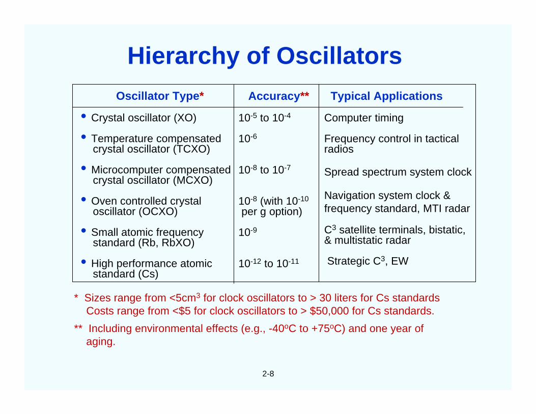
Oscillator Type*
• Crystal oscillator (XO)
• Temperature compensatedcrystal oscillator (TCXO)
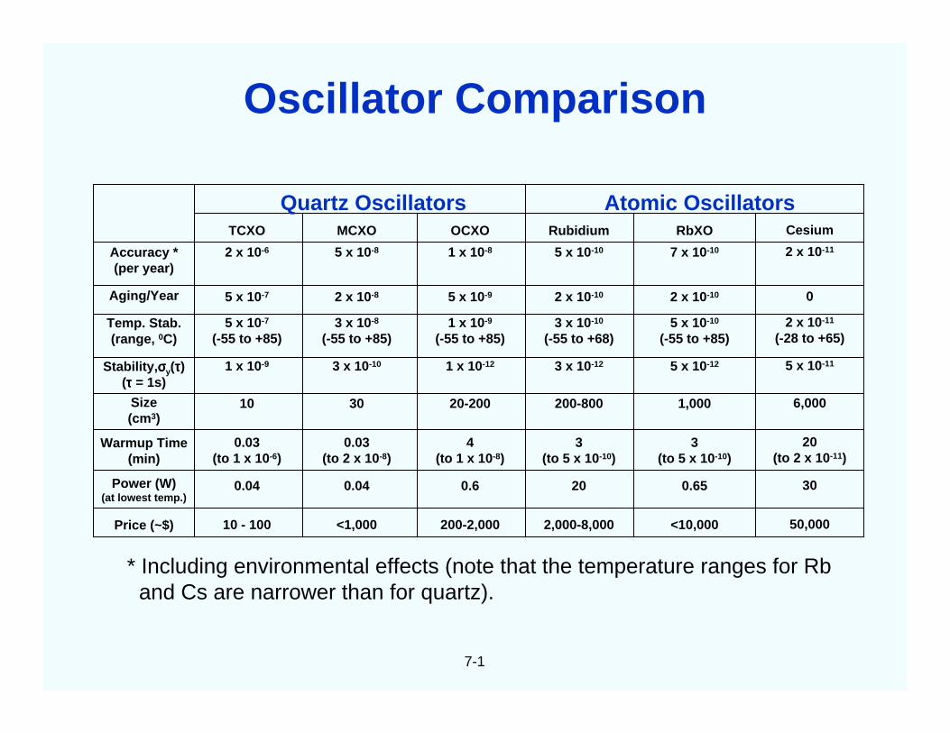
* Sizes range from <5cm3 for clock oscillators to > 30 liters for Cs standardsCosts range from <$5 for clock oscillators to > $50,000 for Cs standards.
** Including environmental effects (e.g., -40oC to +75oC) and one year ofaging.
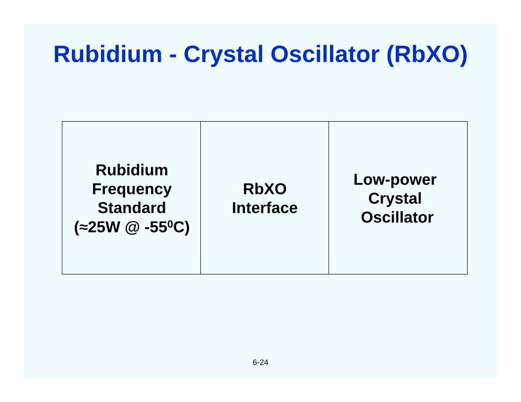
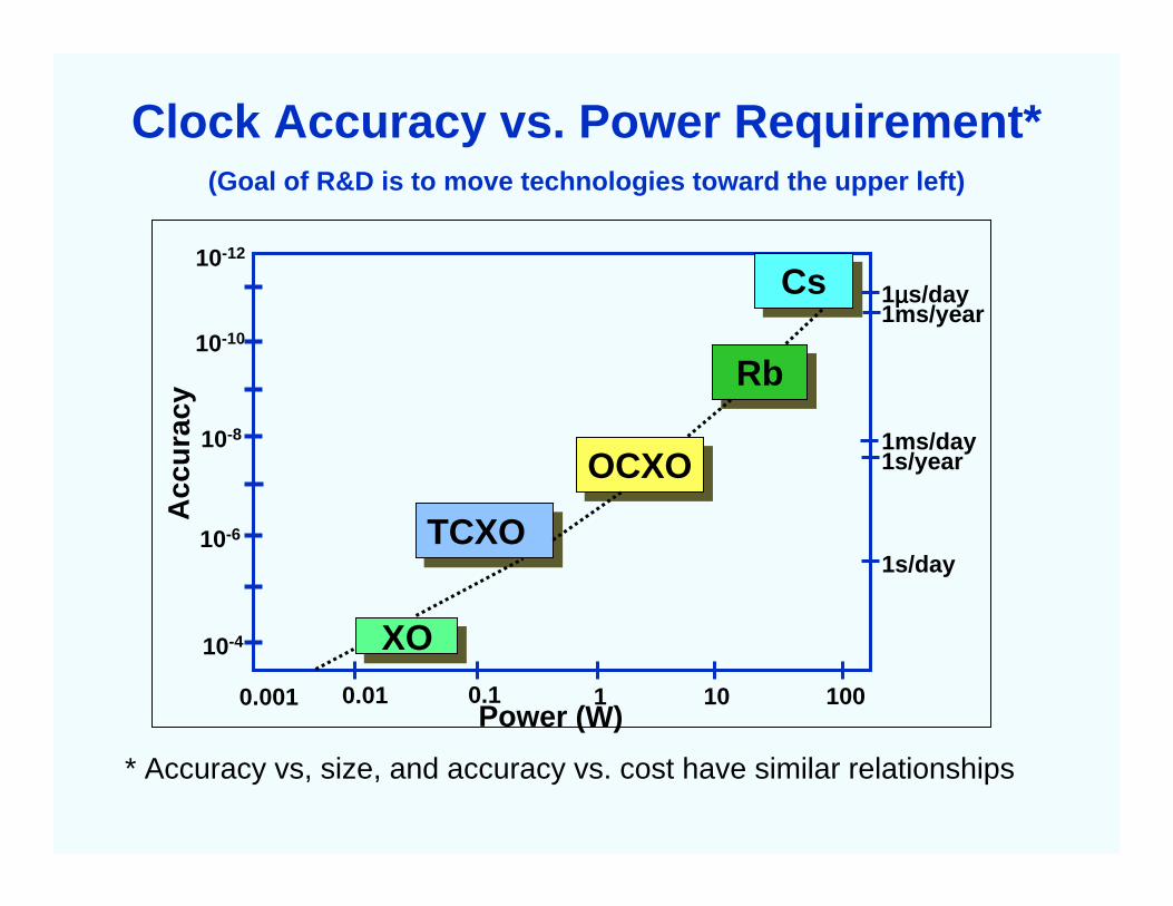
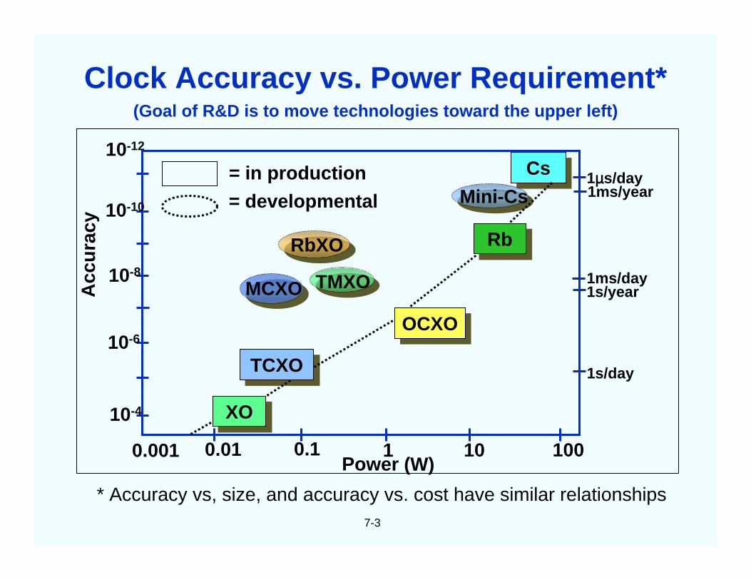
Hierarchy of Oscillators
2-9
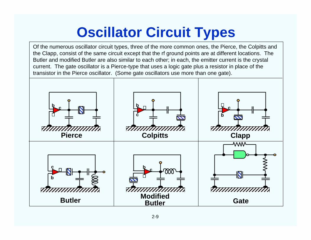
Of the numerous oscillator circuit types, three of the more common ones, the Pierce, the Colpitts andthe Clapp, consist of the same circuit except that the rf ground points are at different locations. TheButler and modified Butler are also similar to each other; in each, the emitter current is the crystalcurrent. The gate oscillator is a Pierce-type that uses a logic gate plus a resistor in place of thetransistor in the Pierce oscillator. (Some gate oscillators use more than one gate).
Pierce Colpitts Clapp
GateModified
ButlerButler
b c∈∈∈∈
b
c∈∈∈∈
b
c∈∈∈∈
b
c ∈∈∈∈ b c∈∈∈∈
Oscillator Circuit Types
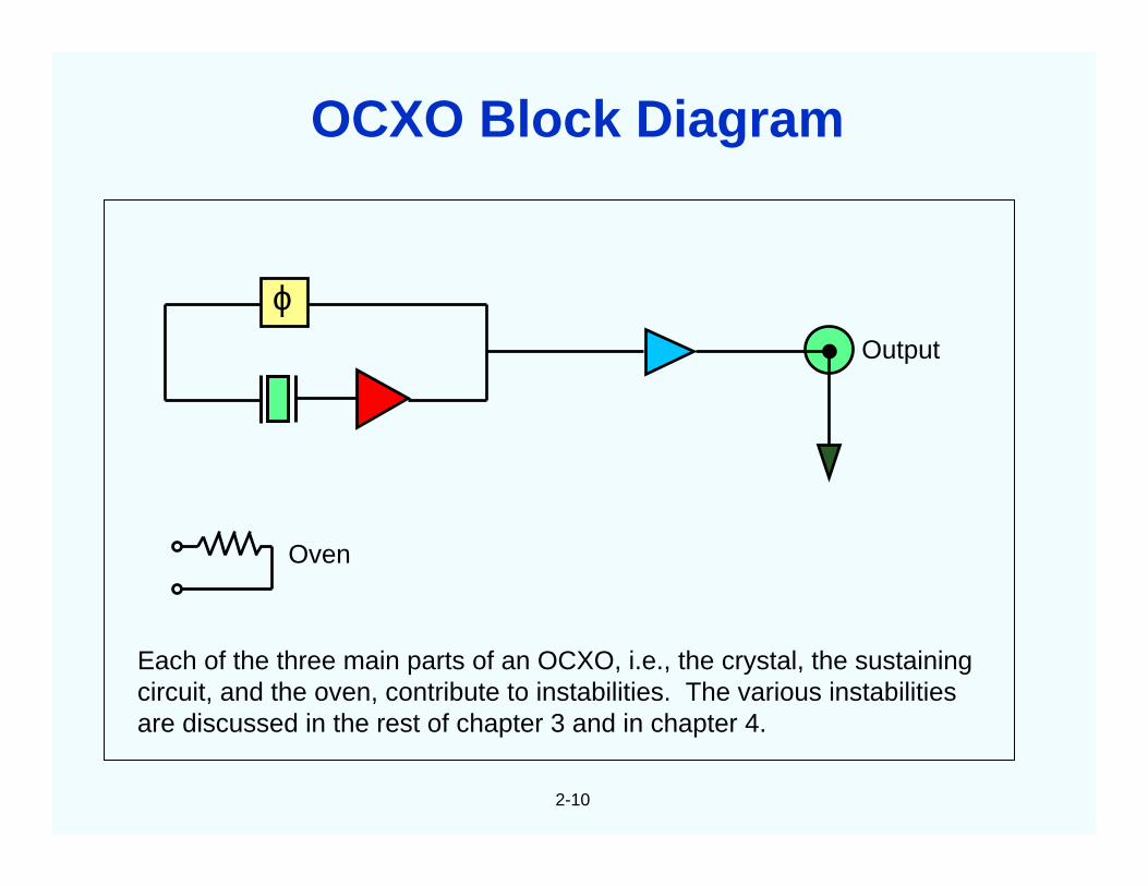
ϕOutput
Oven
2-10
Each of the three main parts of an OCXO, i.e., the crystal, the sustainingcircuit, and the oven, contribute to instabilities. The various instabilitiesare discussed in the rest of chapter 3 and in chapter 4.
OCXO Block Diagram
2-11
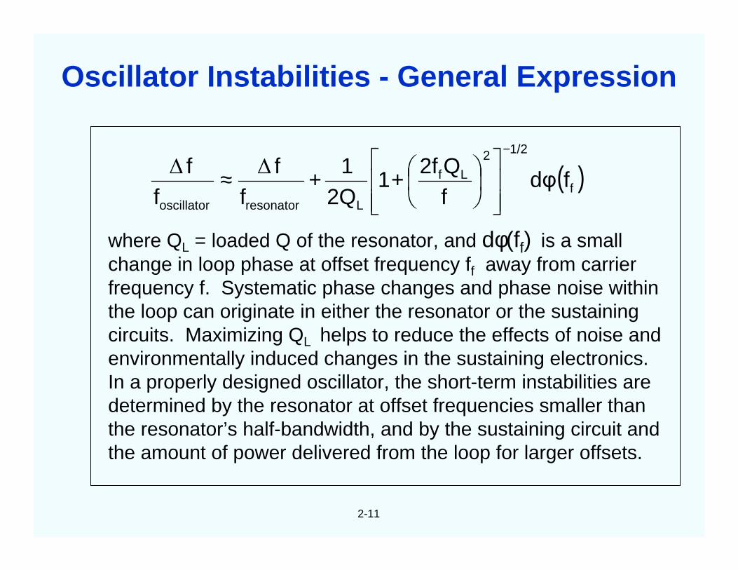
where QL = loaded Q of the resonator, and dφ(ff) is a smallchange in loop phase at offset frequency ff away from carrierfrequency f. Systematic phase changes and phase noise withinthe loop can originate in either the resonator or the sustainingcircuits. Maximizing QL helps to reduce the effects of noise andenvironmentally induced changes in the sustaining electronics.In a properly designed oscillator, the short-term instabilities aredetermined by the resonator at offset frequencies smaller thanthe resonator’s half-bandwidth, and by the sustaining circuit andthe amount of power delivered from the loop for larger offsets.
( )f
1/22
Lf
Lresonatoroscillator
fdφfQ2f
12Q
1f
ff
f−
++≈ ∆∆
Oscillator Instabilities - General Expression
2-12
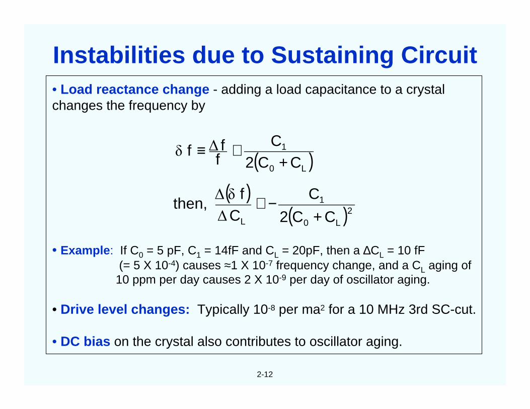
• Load reactance change - adding a load capacitance to a crystalchanges the frequency by
• Example: If C0 = 5 pF, C1 = 14fF and CL = 20pF, then a ∆CL = 10 fF(= 5 X 10⁻⁴) causes ≈1 X 10⁻⁷ frequency change, and a CL aging of10 ppm per day causes 2 X 10⁻⁹ per day of oscillator aging.
• Drive level changes: Typically 10-8 per ma2 for a 10 MHz 3rd SC-cut.
• DC bias on the crystal also contributes to oscillator aging.
( )( )
( )2L0
1
L
L0
1
CC2
CC
fthen,
CC2C
fff
+−≅
+≅≡
∆
δ∆
∆δ
Instabilities due to Sustaining Circuit
2-13
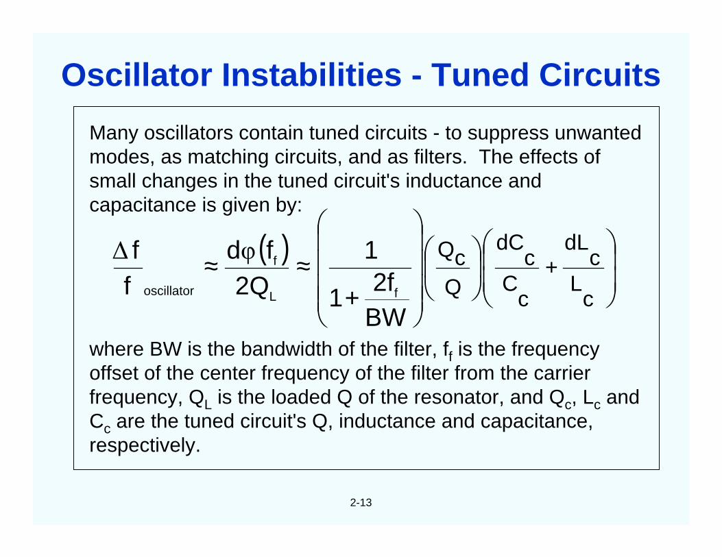
Many oscillators contain tuned circuits - to suppress unwantedmodes, as matching circuits, and as filters. The effects ofsmall changes in the tuned circuit's inductance andcapacitance is given by:
where BW is the bandwidth of the filter, ff is the frequencyoffset of the center frequency of the filter from the carrierfrequency, QL is the loaded Q of the resonator, and Qc, Lc andCc are the tuned circuit's Q, inductance and capacitance,respectively.
( )
+≈≈ +
cL
cdL
cC
cdC
QcQ
BW2f
1
12Q
fdff
fL
f
oscillator
φ∆
Oscillator Instabilities - Tuned Circuits
2-14
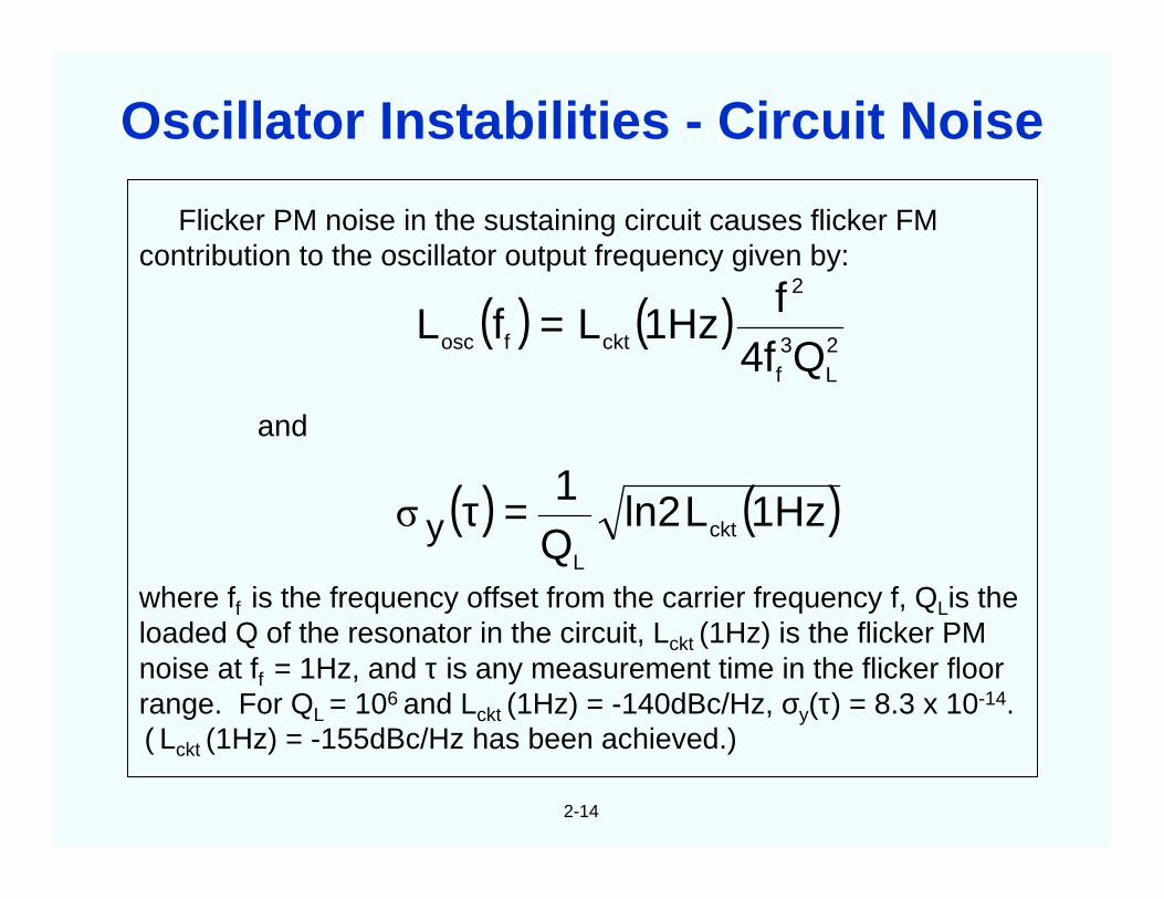
Flicker PM noise in the sustaining circuit causes flicker FMcontribution to the oscillator output frequency given by:
where ff is the frequency offset from the carrier frequency f, QLis theloaded Q of the resonator in the circuit, Lckt (1Hz) is the flicker PMnoise at ff = 1Hz, and τ is any measurement time in the flicker floorrange. For QL = 106 and Lckt (1Hz) = -140dBc/Hz, σy(τ) = 8.3 x 10⁻¹⁴.( Lckt (1Hz) = -155dBc/Hz has been achieved.)
( ) ( )
( ) ( )1Hzln2Q1
Q4ff
1Hzf
ckt
L
2L
3f
2
cktfosc
y
and
L
LL
=τ
=
σ
Oscillator Instabilities - Circuit Noise
2-15
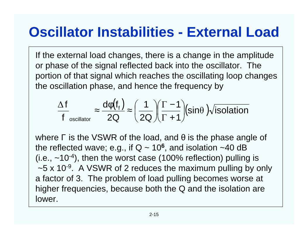
If the external load changes, there is a change in the amplitudeor phase of the signal reflected back into the oscillator. Theportion of that signal which reaches the oscillating loop changesthe oscillation phase, and hence the frequency by
where Γ is the VSWR of the load, and θ is the phase angle ofthe reflected wave; e.g., if Q ~ 106, and isolation ~40 dB(i.e., ~10-4), then the worst case (100% reflection) pulling is~5 x 10⁻⁹. A VSWR of 2 reduces the maximum pulling by only
a factor of 3. The problem of load pulling becomes worse athigher frequencies, because both the Q and the isolation arelower.
( ) ( ) isolationsin11
2Q1
2Qfd
ff f
oscillatorθ
Γ
Γ∆
+−
≈φ≈
Oscillator Instabilities - External Load
2-16
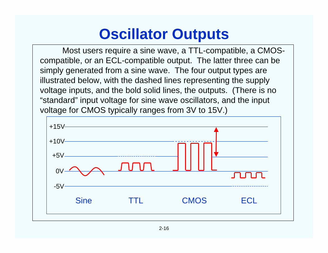
Most users require a sine wave, a TTL-compatible, a CMOS-compatible, or an ECL-compatible output. The latter three can besimply generated from a sine wave. The four output types areillustrated below, with the dashed lines representing the supplyvoltage inputs, and the bold solid lines, the outputs. (There is no“standard” input voltage for sine wave oscillators, and the inputvoltage for CMOS typically ranges from 3V to 15V.)
Quartz is the only material known that possesses the followingcombination of properties:
• Piezoelectric ("pressure-electric"; piezein = to press, in Greek)
• Zero temperature coefficient cuts exist
• Stress compensated cut exists
• Low loss (i.e., high Q)
• Easy to process; low solubility in everything, under "normal" conditions,except the fluoride etchants; hard but not brittle
• Abundant in nature; easy to grow in large quantities, at low cost, andwith relatively high purity and perfection. Of the man-grown singlecrystals, quartz, at ~3,000 tons per year, is second only to silicon inquantity grown (3 to 4 times as much Si is grown annually, as of 1997).
Why Quartz?
3-2
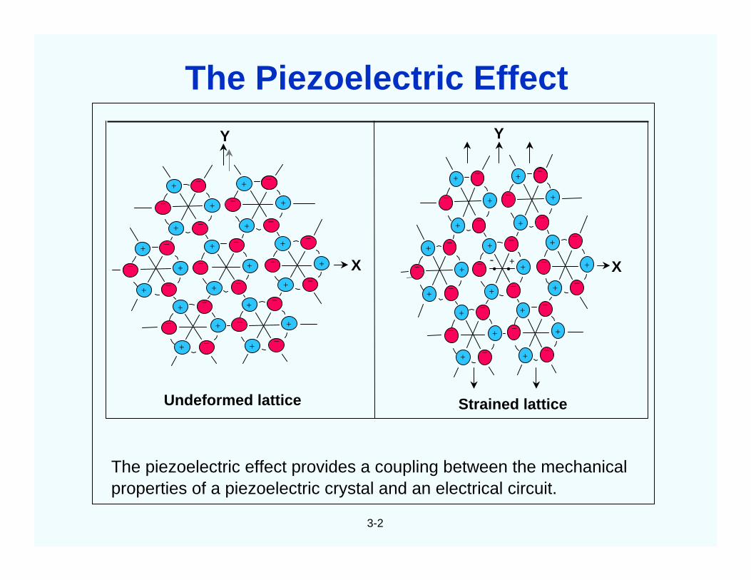
The piezoelectric effect provides a coupling between the mechanicalproperties of a piezoelectric crystal and an electrical circuit.
Undeformed lattice
X
+
+
+
+
+
+
+
+
+
+
+
+
+
+
+
+
+
+
+
++
__
_
_ _
_ _
_
_
_
_
_ _
_
_
_
_
_
_
_
Strained lattice
+
+
+
+
+
+
+
+
+
+
+
+
+
+
+
+
+
+
+
++
__
_
_ _
_ _
_
_
_
__
_ _
_
_
_
_
_
_
_
X• •- +
YY
__
The Piezoelectric Effect
3-3
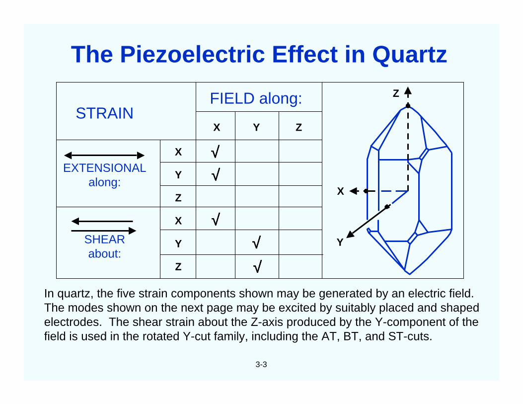
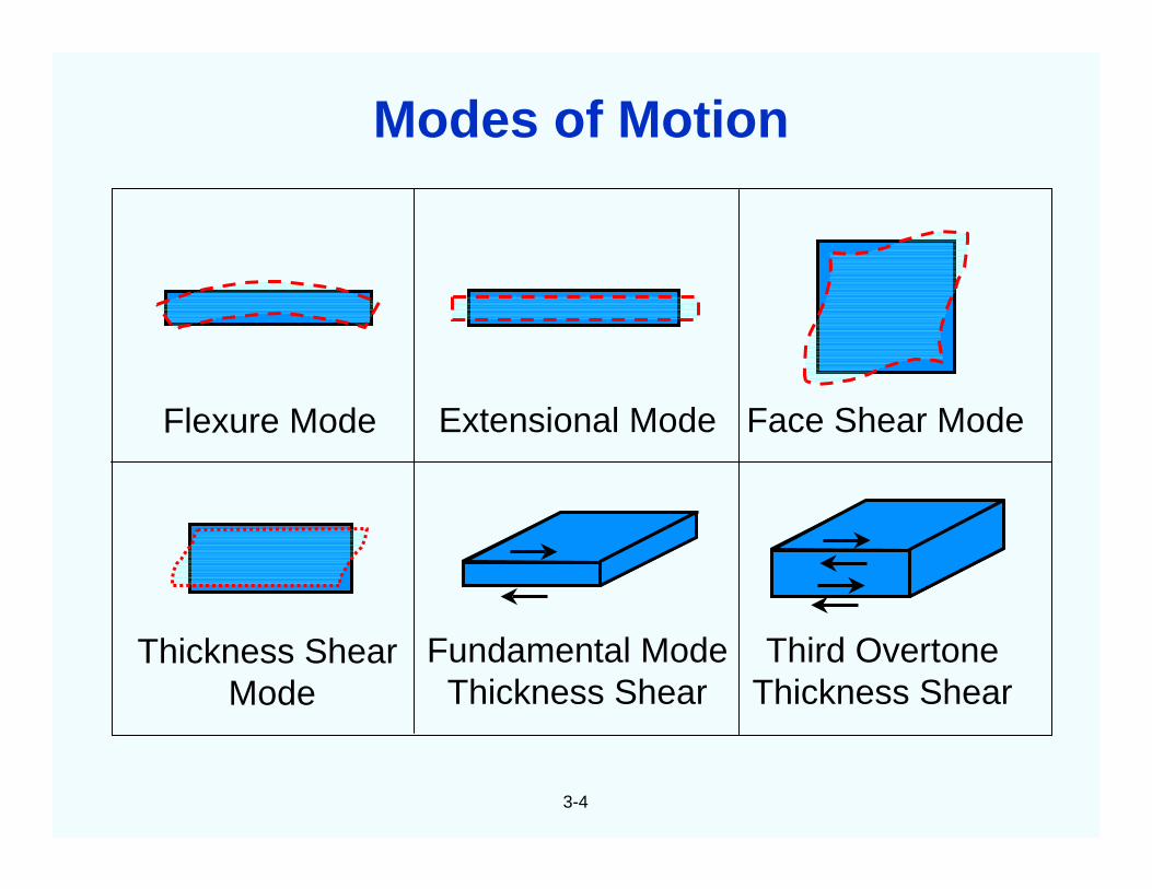
In quartz, the five strain components shown may be generated by an electric field.The modes shown on the next page may be excited by suitably placed and shapedelectrodes. The shear strain about the Z-axis produced by the Y-component of thefield is used in the rotated Y-cut family, including the AT, BT, and ST-cuts.
STRAIN
EXTENSIONALalong:
SHEARabout:
FIELD along:
X
Y
Z
X
Y
Z
X Y Z
√√√√√√√√
√√√√√√√√√√√√
X
Y
Z
The Piezoelectric Effect in Quartz
3-4
Flexure Mode Extensional Mode Face Shear Mode
Thickness ShearMode
Fundamental ModeThickness Shear
Third OvertoneThickness Shear
Modes of Motion
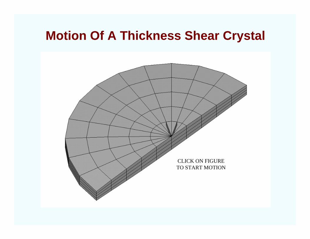
Motion Of A Thickness Shear Crystal
CLICK ON FIGURETO START MOTION
3-5
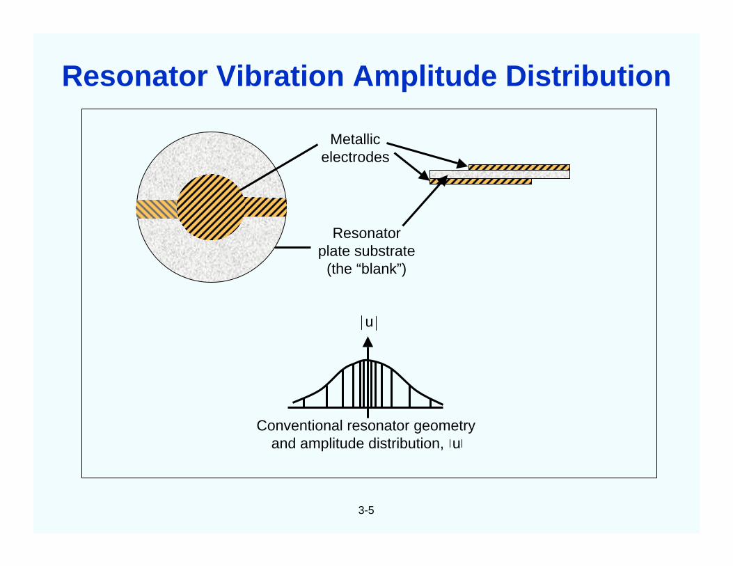
Metallicelectrodes
Resonatorplate substrate
(the “blank”)
u
Conventional resonator geometryand amplitude distribution, u
Resonator Vibration Amplitude Distribution
3-6
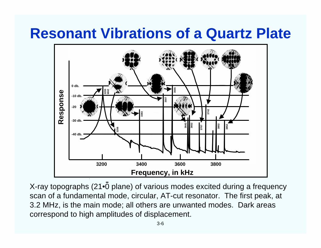
X-ray topographs (21•0 plane) of various modes excited during a frequencyscan of a fundamental mode, circular, AT-cut resonator. The first peak, at3.2 MHz, is the main mode; all others are unwanted modes. Dark areascorrespond to high amplitudes of displacement.
3200 3400 3600 3800
0 db.
-10 db.
-20
-30 db.
-40 db.
Frequency, in kHz
Res
po
nse 32
00M
HZ
3256
3383
3507
3555
3642
3652
3707
3742
3802
3852
Resonant Vibrations of a Quartz Plate
0
jX
-jX
Rea
ctan
ce
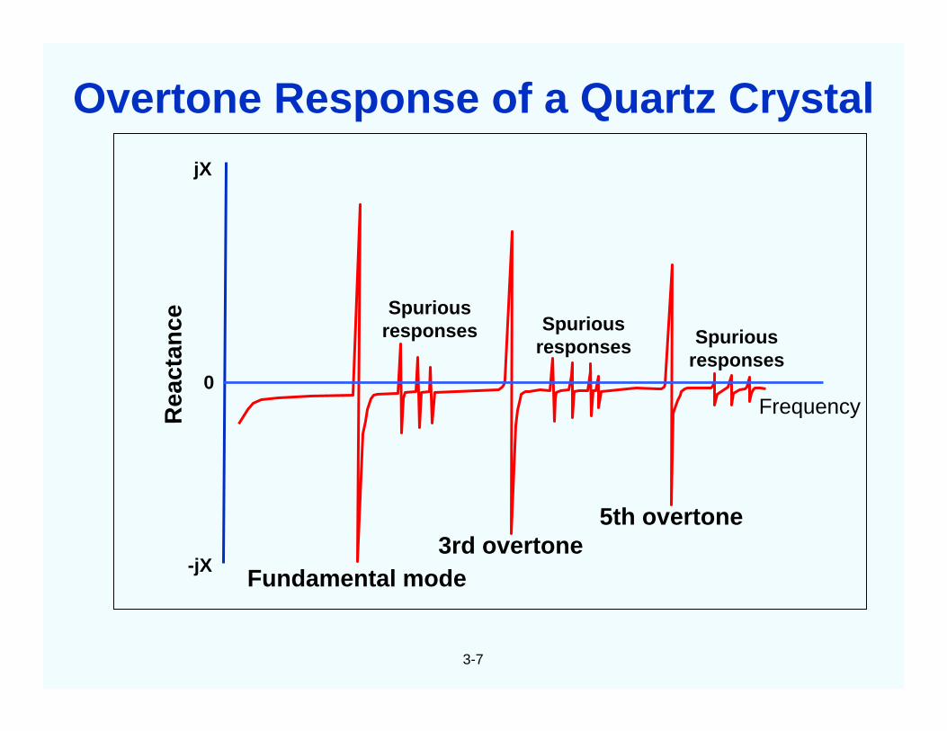
Fundamental mode3rd overtone
5th overtone
Frequency
Spuriousresponses Spurious
responses
3-7
Spuriousresponses
Overtone Response of a Quartz Crystal
3-8
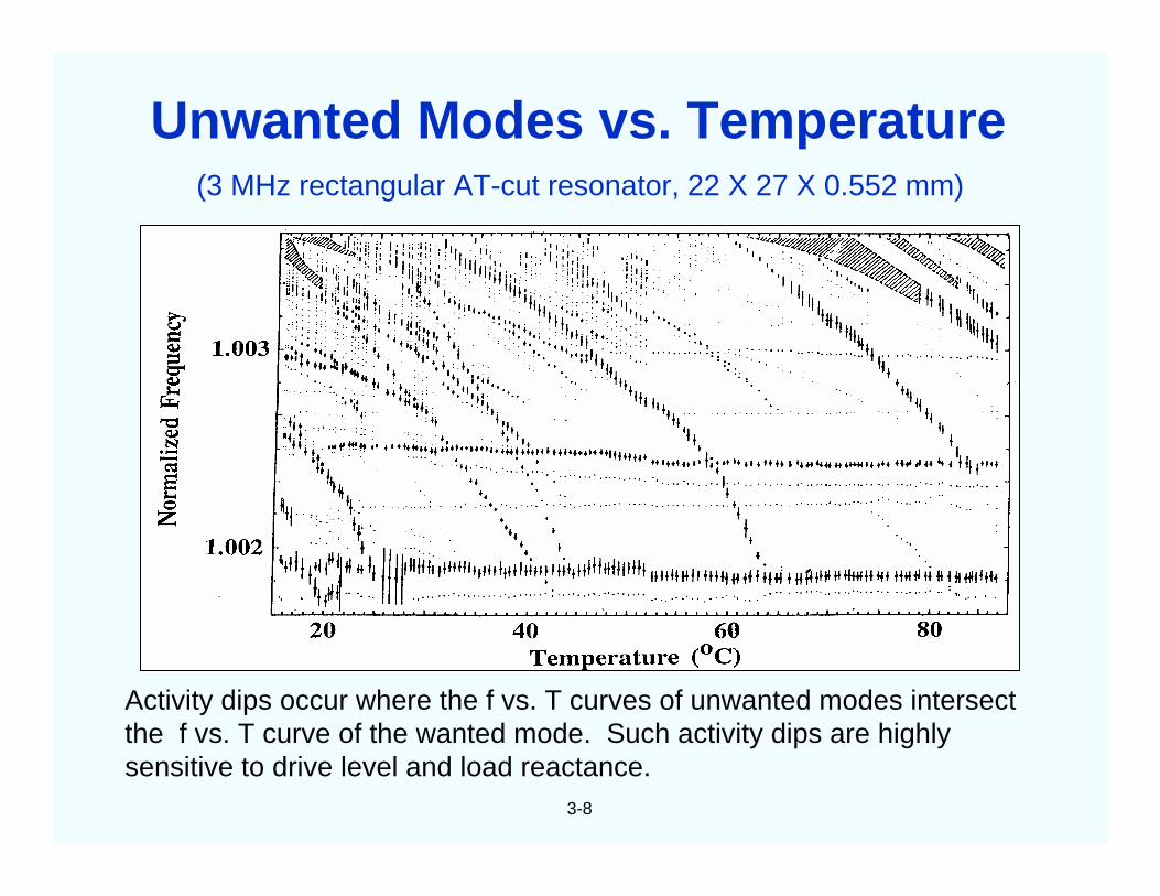
(3 MHz rectangular AT-cut resonator, 22 X 27 X 0.552 mm)
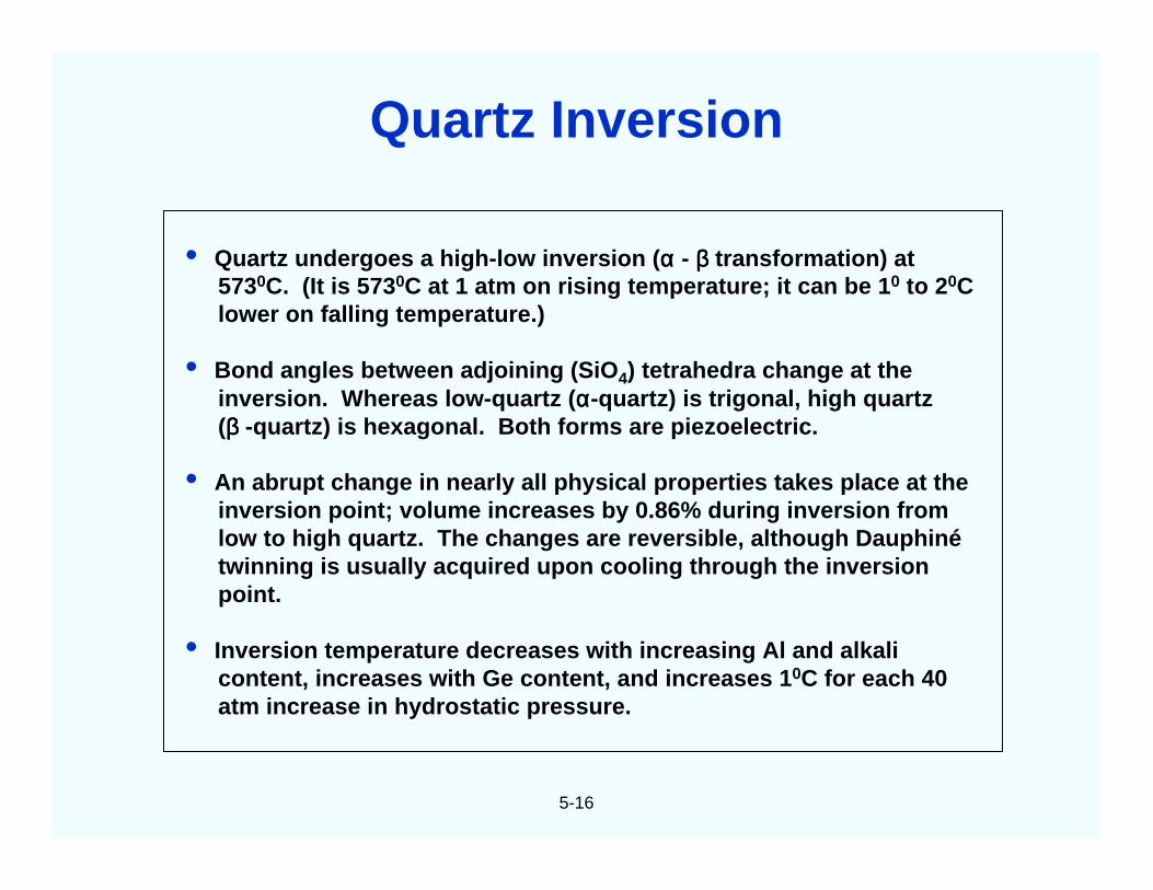
Activity dips occur where the f vs. T curves of unwanted modes intersectthe f vs. T curve of the wanted mode. Such activity dips are highlysensitive to drive level and load reactance.
Unwanted Modes vs. Temperature
3-9
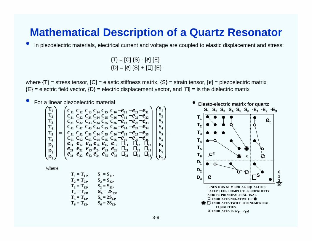
• In piezoelectric materials, electrical current and voltage are coupled to elastic displacement and stress:
T = [C] S - [e] E
D = [e] S + [∈∈∈∈ ] E
where T = stress tensor, [C] = elastic stiffness matrix, S = strain tensor, [e] = piezoelectric matrixE = electric field vector, D = electric displacement vector, and [∈∈∈∈ ] = is the dielectric matrix
LINES JOIN NUMERICAL EQUALITIESEXCEPT FOR COMPLETE RECIPROCITYACROSS PRINCIPAL DIAGONAL
INDICATES NEGATIVE OFINDICATES TWICE THE NUMERICAL
EQUALITIESINDICATES 1/2 (c11 - c12)X
∈∈∈∈
Mathematical Description of a Quartz Resonator
3-10
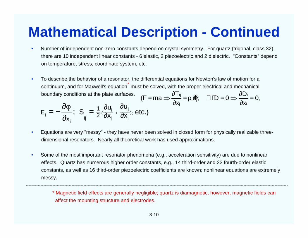
• Number of independent non-zero constants depend on crystal symmetry. For quartz (trigonal, class 32),
there are 10 independent linear constants - 6 elastic, 2 piezoelectric and 2 dielectric. "Constants” depend
on temperature, stress, coordinate system, etc.
• To describe the behavior of a resonator, the differential equations for Newton's law of motion for a
continuum, and for Maxwell's equation* must be solved, with the proper electrical and mechanical
boundary conditions at the plate surfaces.
• Equations are very "messy" - they have never been solved in closed form for physically realizable three-
dimensional resonators. Nearly all theoretical work has used approximations.
• Some of the most important resonator phenomena (e.g., acceleration sensitivity) are due to nonlinear
effects. Quartz has numerous higher order constants, e.g., 14 third-order and 23 fourth-order elastic
constants, as well as 16 third-order piezoelectric coefficients are known; nonlinear equations are extremely
messy.
* Magnetic field effects are generally negligible; quartz is diamagnetic, however, magnetic fields can
affect the mounting structure and electrodes.
,0xD
0D;uρxT
ma(Fi
ii
j
ij =∂∂
⇒=⋅∇=∂∂
⇒= &&
).; etcxu
xu
S ;)i
j
j
i(2
1
xE
iji
i ∂∂
∂∂
+=∂∂−= φ
Mathematical Description - Continued
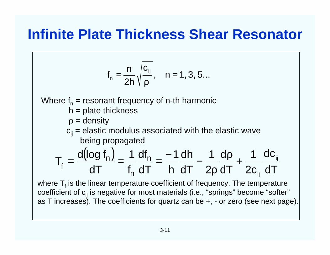
3-11
Where fn = resonant frequency of n-th harmonich = plate thicknessρ = densitycij = elastic modulus associated with the elastic wave
being propagated
where Tf is the linear temperature coefficient of frequency. The temperaturecoefficient of cij is negative for most materials (i.e., “springs” become “softer”as T increases). The coefficients for quartz can be +, - or zero (see next page).
5...3,1,n,ρ
c
2hn
f ijn ==
( )dT
dc
2c1
dTd
21
dTdh
h1
dTdf
f1
dTflogd
T ij
ij
n
n
nf +ρ
ρ−−===
Infinite Plate Thickness Shear Resonator
3-12
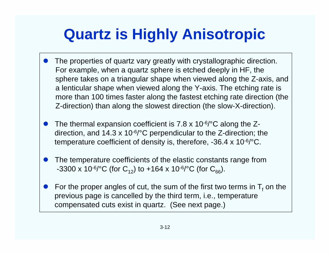
The properties of quartz vary greatly with crystallographic direction.For example, when a quartz sphere is etched deeply in HF, thesphere takes on a triangular shape when viewed along the Z-axis, anda lenticular shape when viewed along the Y-axis. The etching rate ismore than 100 times faster along the fastest etching rate direction (theZ-direction) than along the slowest direction (the slow-X-direction).
The thermal expansion coefficient is 7.8 x 10⁻⁶/°C along the Z-direction, and 14.3 x 10⁻⁶/°C perpendicular to the Z-direction; thetemperature coefficient of density is, therefore, -36.4 x 10⁻⁶/°C.
The temperature coefficients of the elastic constants range from-3300 x 10-6/°C (for C12) to +164 x 10-6/°C (for C66).
For the proper angles of cut, the sum of the first two terms in Tf on theprevious page is cancelled by the third term, i.e., temperaturecompensated cuts exist in quartz. (See next page.)
Quartz is Highly Anisotropic
3-13
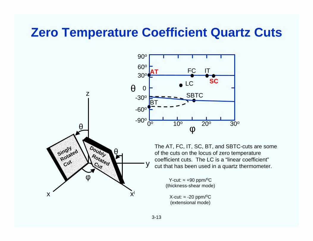
x xl
y
φ
z
θ
θ
The AT, FC, IT, SC, BT, and SBTC-cuts are someof the cuts on the locus of zero temperaturecoefficient cuts. The LC is a “linear coefficient”cut that has been used in a quartz thermometer.
Y-cut: ≈ +90 ppm/0C(thickness-shear mode)
X-cut: ≈ -20 ppm/0C(extensional mode)
90o
60o
30o
0
-30o
-60o
-90o0o 10o 20o 30o
AT FC IT
LC SC
SBTCBT
θ
φ
Singly
Rotated
Cut
DoublyRotatedCut
Zero Temperature Coefficient Quartz Cuts
3-14
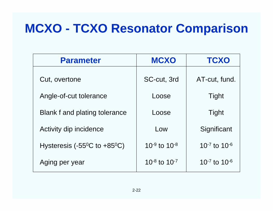
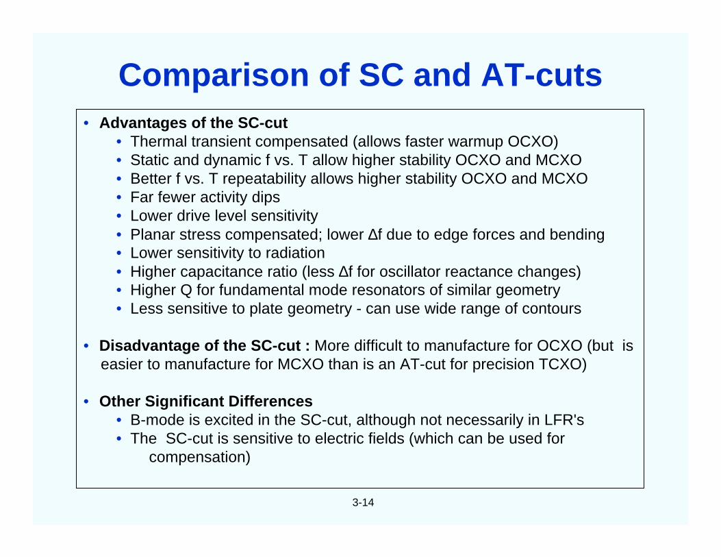
• Advantages of the SC-cut• Thermal transient compensated (allows faster warmup OCXO)• Static and dynamic f vs. T allow higher stability OCXO and MCXO• Better f vs. T repeatability allows higher stability OCXO and MCXO• Far fewer activity dips• Lower drive level sensitivity• Planar stress compensated; lower ∆f due to edge forces and bending• Lower sensitivity to radiation• Higher capacitance ratio (less ∆f for oscillator reactance changes)• Higher Q for fundamental mode resonators of similar geometry• Less sensitive to plate geometry - can use wide range of contours
• Disadvantage of the SC-cut : More difficult to manufacture for OCXO (but iseasier to manufacture for MCXO than is an AT-cut for precision TCXO)
• Other Significant Differences• B-mode is excited in the SC-cut, although not necessarily in LFR's• The SC-cut is sensitive to electric fields (which can be used for
compensation)
Comparison of SC and AT-cuts
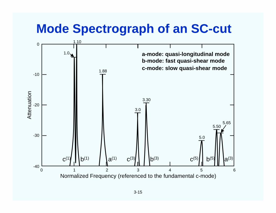
Atte
nuat
ion
Normalized Frequency (referenced to the fundamental c-mode)
0
-20
-10
-30
-400 1 2 3 4 5 6
1.0
1.10
1.88
3.0
3.30
5.0
5.505.65
c(1) b(1) a(1) c(3) b(3) c(5) b(5) a(3)
3-15
a-mode: quasi-longitudinal modeb-mode: fast quasi-shear modec-mode: slow quasi-shear mode
Mode Spectrograph of an SC-cut
400
200
0
-200
-400
-600
-800
-1000
-1200
0 10 20
30 40 50 60 70
b-Mode (Fast Shear)-25.5 ppm/oC
c-Mode (Slow Shear)
Temperature (OC)
FR
EQ
UE
NC
YD
EV
IAT
ION
(PP
M)
3-16
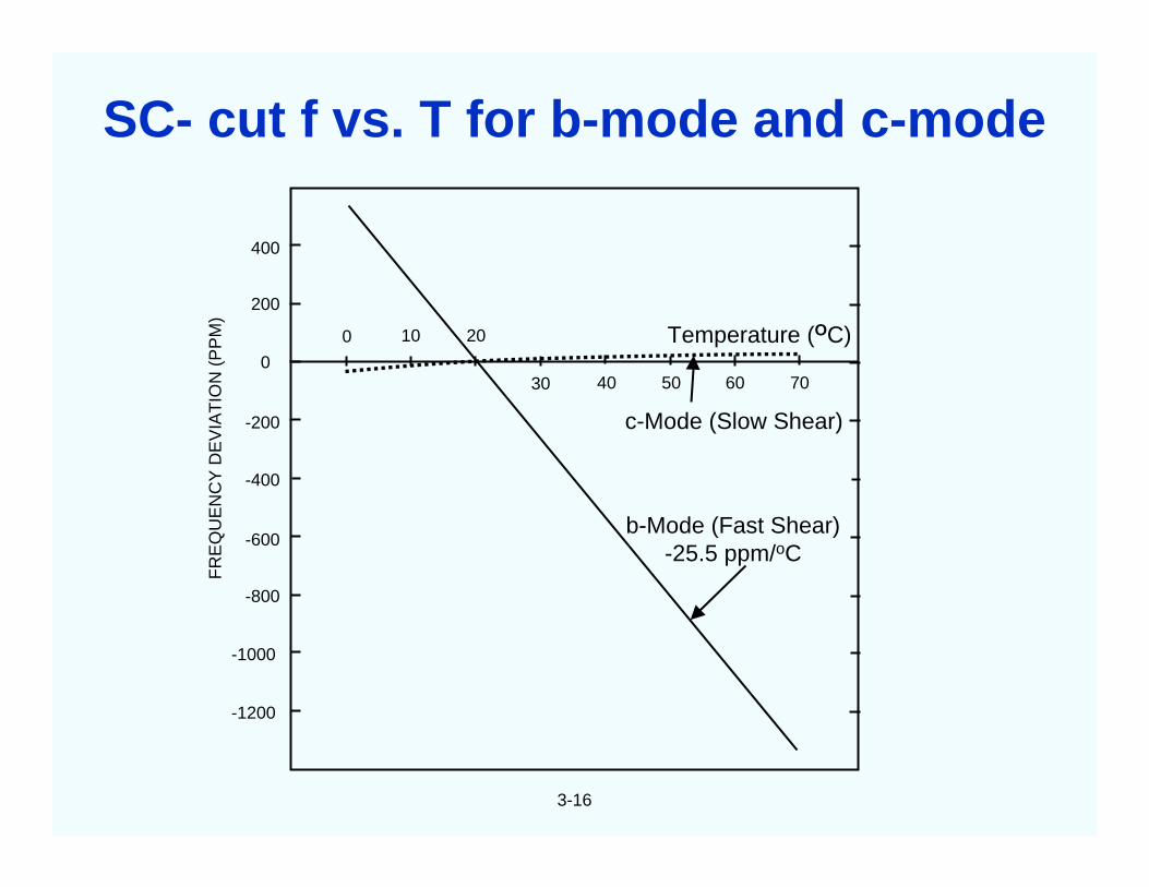
SC- cut f vs. T for b-mode and c-mode
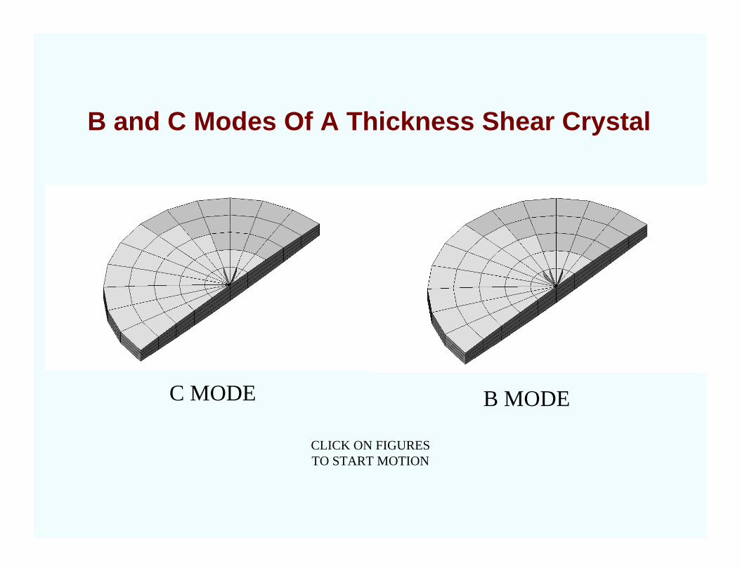
B and C Modes Of A Thickness Shear Crystal
C MODE B MODE
CLICK ON FIGURESTO START MOTION
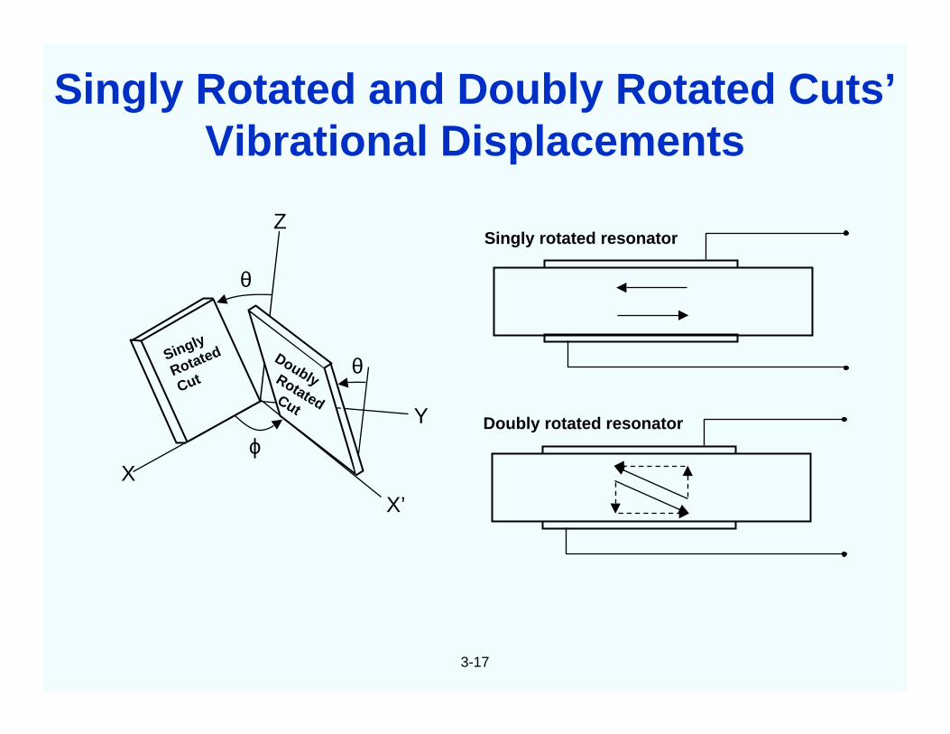
Singly
Rotated
Cut
DoublyRotatedCut
XX’
Y
θ
θ
ϕ
Z
3-17
Singly Rotated and Doubly Rotated Cuts’Vibrational Displacements
Singly rotated resonator
Doubly rotated resonator
3-18
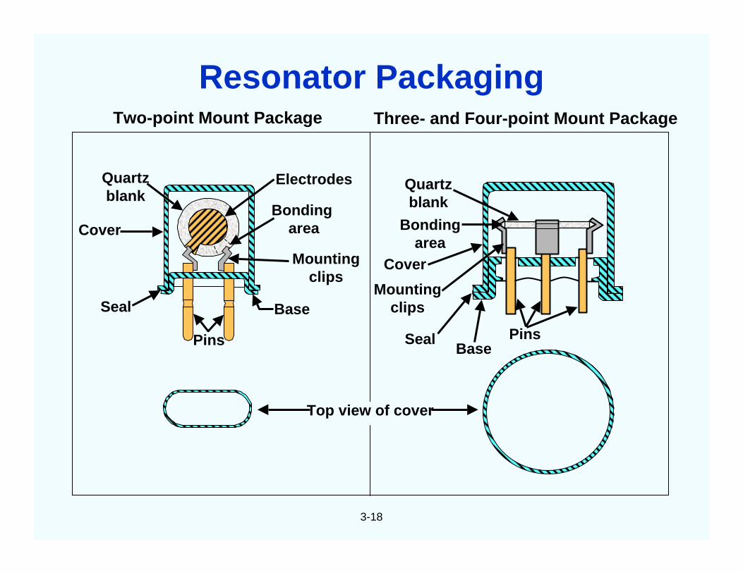
Base
Mountingclips
Bondingarea
ElectrodesQuartzblank
Cover
Seal
Pins
Quartzblank
Bondingarea
Cover
Mountingclips
SealBase
Pins
Two-point Mount Package Three- and Four-point Mount Package
Top view of cover
Resonator Packaging
3-19
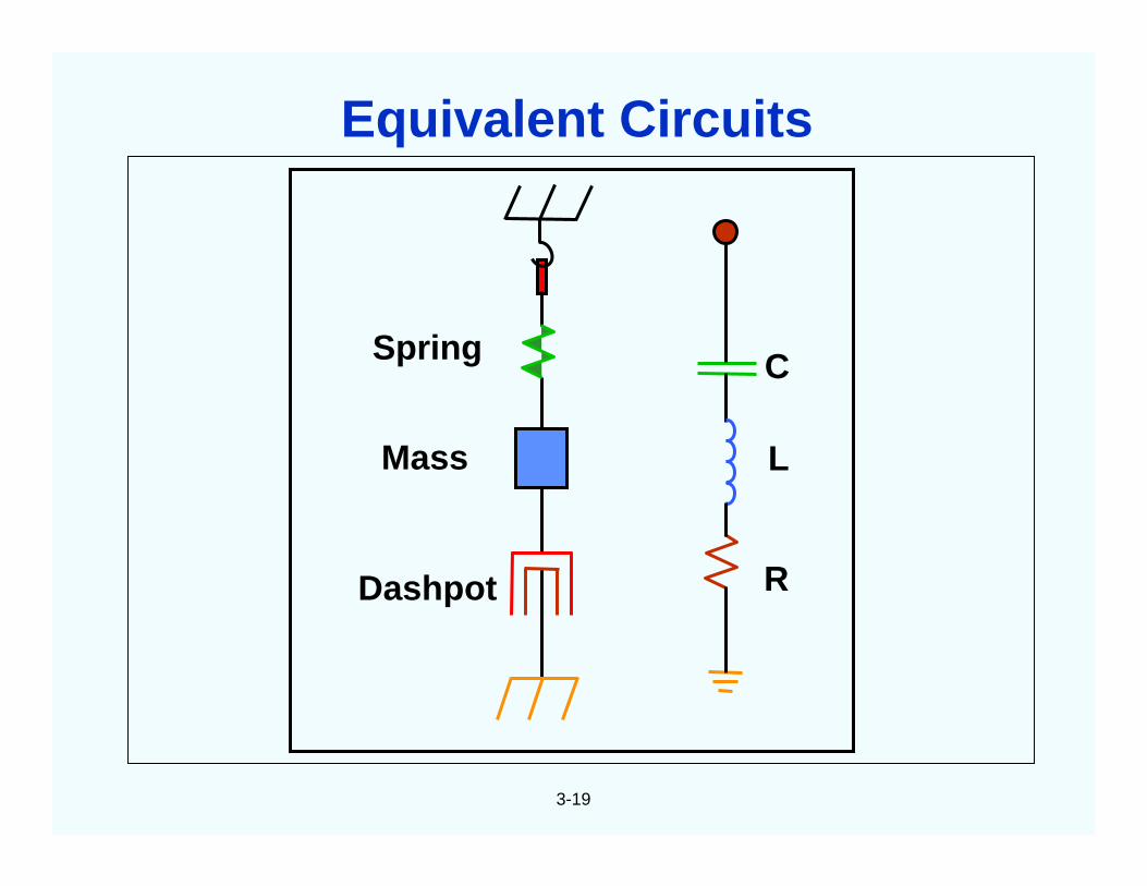
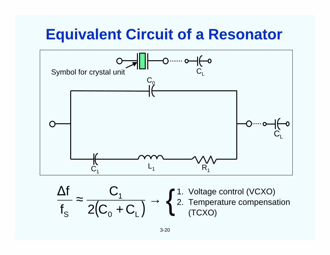
C
L
R
Spring
Mass
Dashpot
Equivalent Circuits
3-20
1. Voltage control (VCXO)2. Temperature compensation
(TCXO)( ) →+
≈L0
1
S CC2C
f∆f
Symbol for crystal unit CL
C1L1 R1
C0
CL
Equivalent Circuit of a Resonator
3-21
Compensatedfrequencyof TCXO
Compensatingvoltage
on varactor CL
Fre
qu
ency
/Vo
ltag
e
Uncompensatedfrequency
T
Crystal Oscillator f vs. T Compensation
3-22
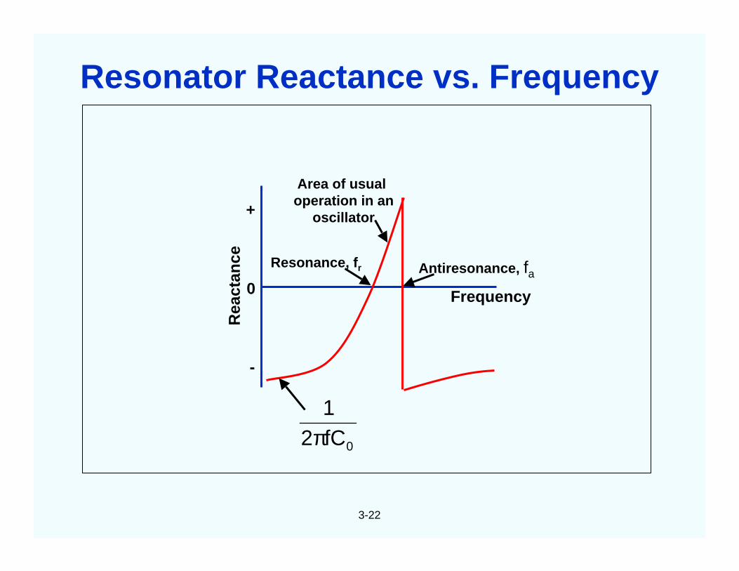
0
+
-
Rea
ctan
ce
0fC21
π
Area of usualoperation in an
oscillator
Antiresonance, fa
Frequency
Resonance, fr
Resonator Reactance vs. Frequency
3-23
tA
C ε0 ≅1
0
CC
r ≡
1CL1
21
sf1π
=2rf
ff ssa ≅−
11CRf21
QSπ
=
s10CR 14111
−≅=τ
311
1n nCr'
C ≈ 311
3
1n 'rLn
L ≈
1
11
RC1
Lω
ω −=ϕ
sfQ360
dfd
π≅ϕ
r'Rn
R 113
1n ≈2
2kn
2r
= π
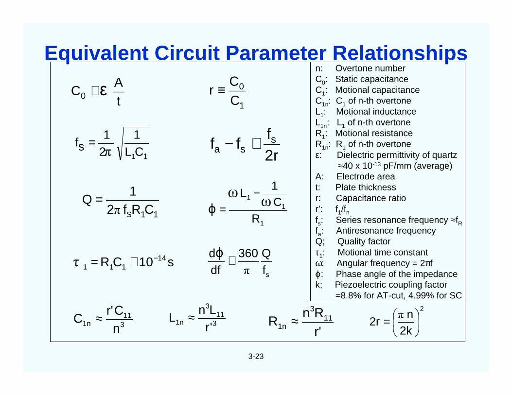
n: Overtone numberC0: Static capacitanceC1: Motional capacitanceC1n: C1 of n-th overtoneL1: Motional inductanceL1n: L1 of n-th overtoneR1: Motional resistanceR1n: R1 of n-th overtoneε: Dielectric permittivity of quartz
≈40 x 10-13 pF/mm (average)A: Electrode areat: Plate thicknessr: Capacitance ratior’: f1/fnfs: Series resonance frequency ≈fRfa: Antiresonance frequencyQ; Quality factorτ1: Motional time constantω: Angular frequency = 2πfϕ: Phase angle of the impedancek; Piezoelectric coupling factor
=8.8% for AT-cut, 4.99% for SC
Equivalent Circuit Parameter Relationships
3-24
Q is proportional to the decay-time, and is inverselyproportional to the linewidth of resonance (see next page).
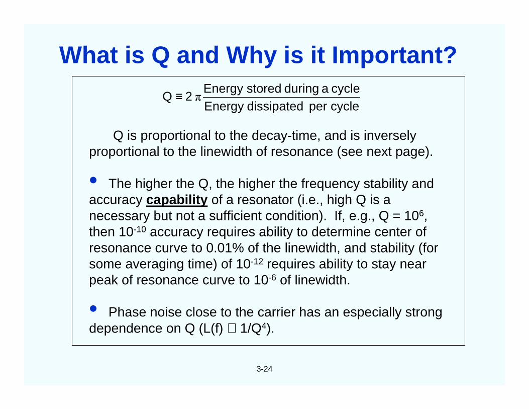
• The higher the Q, the higher the frequency stability andaccuracy capability of a resonator (i.e., high Q is anecessary but not a sufficient condition). If, e.g., Q = 106,then 10-10 accuracy requires ability to determine center ofresonance curve to 0.01% of the linewidth, and stability (forsome averaging time) of 10-12 requires ability to stay nearpeak of resonance curve to 10-6 of linewidth.
• Phase noise close to the carrier has an especially strongdependence on Q (L(f) ∝ 1/Q4).
cycleperdissipatedEnergycycleaduringstoredEnergy
2Q π≡
What is Q and Why is it Important?
3-25
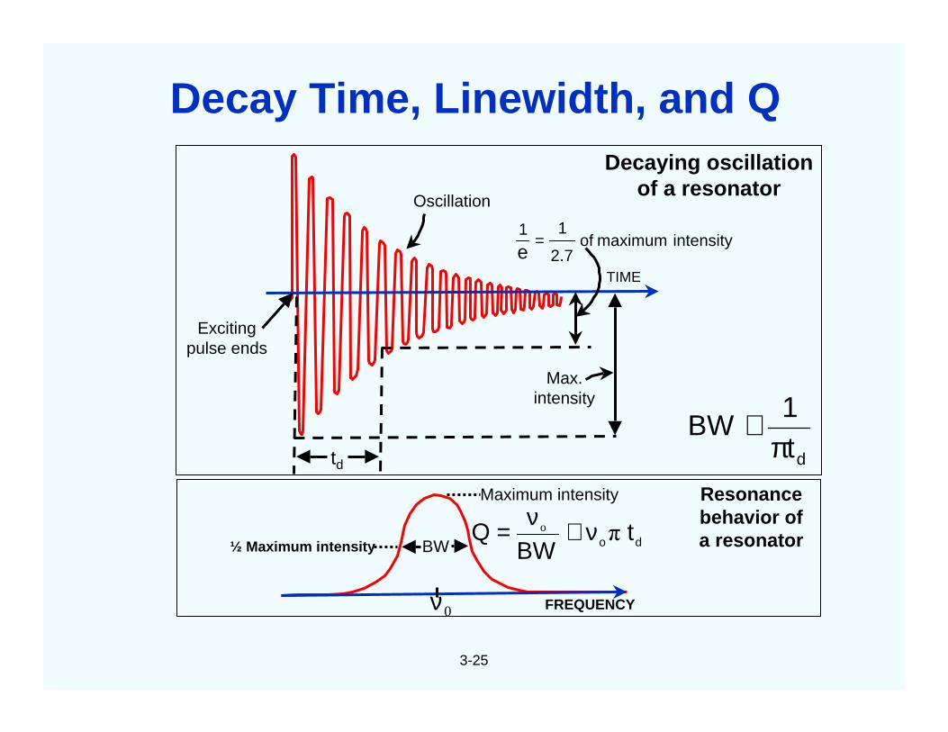
Oscillation
Excitingpulse ends
TIME
intensitymaximumof2.7
11
e=
Decaying oscillationof a resonator
dt1
BWπ
≅td
Max.intensity
BW
Maximum intensity
do tBW
Q πo ν≅ν=
FREQUENCY
Resonancebehavior ofa resonator
0ν
½ Maximum intensity
Decay Time, Linewidth, and Q
3-26
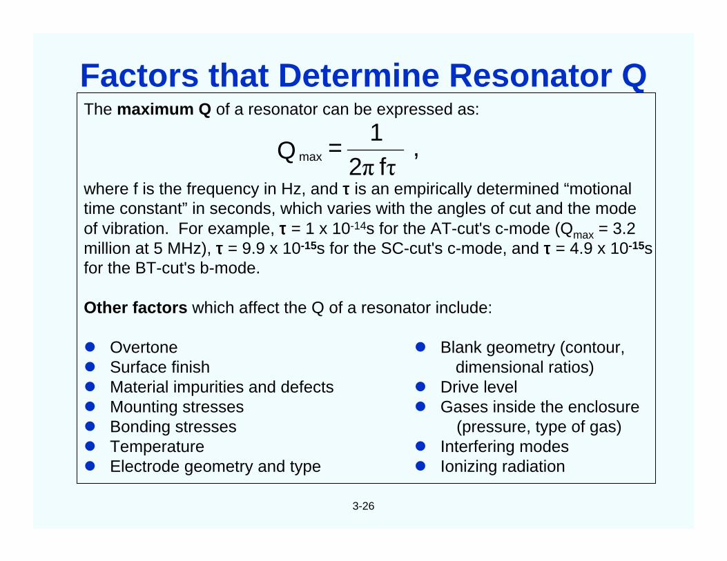
The maximum Q of a resonator can be expressed as:
where f is the frequency in Hz, and ττττ is an empirically determined “motionaltime constant” in seconds, which varies with the angles of cut and the modeof vibration. For example, ττττ = 1 x 10-14s for the AT-cut's c-mode (Qmax = 3.2million at 5 MHz), ττττ = 9.9 x 10⁻¹⁵s for the SC-cut's c-mode, and ττττ = 4.9 x 10⁻¹⁵sfor the BT-cut's b-mode.
Other factors which affect the Q of a resonator include:
Overtone Blank geometry (contour, Surface finish dimensional ratios) Material impurities and defects Drive level Mounting stresses Gases inside the enclosure Bonding stresses (pressure, type of gas) Temperature Interfering modes Electrode geometry and type Ionizing radiation
,f2
1=Q max
τπ
Factors that Determine Resonator Q
3-27
SEAL BAKEPLATEFINALCLEAN
FREQUENCYADJUST
CLEANINSPECTBONDMOUNTPREPARE
ENCLOSUREDEPOSIT
CONTACTS
ORIENTIN MASK
CLEANETCH
(CHEMICALPOLISH)
CONTOURANGLE
CORRECTX-RAY
ORIENT
ROUNDLAPCUTSWEEPGROW
QUARTZDESIGN
RESONATORS
TEST
OSCILLATOR
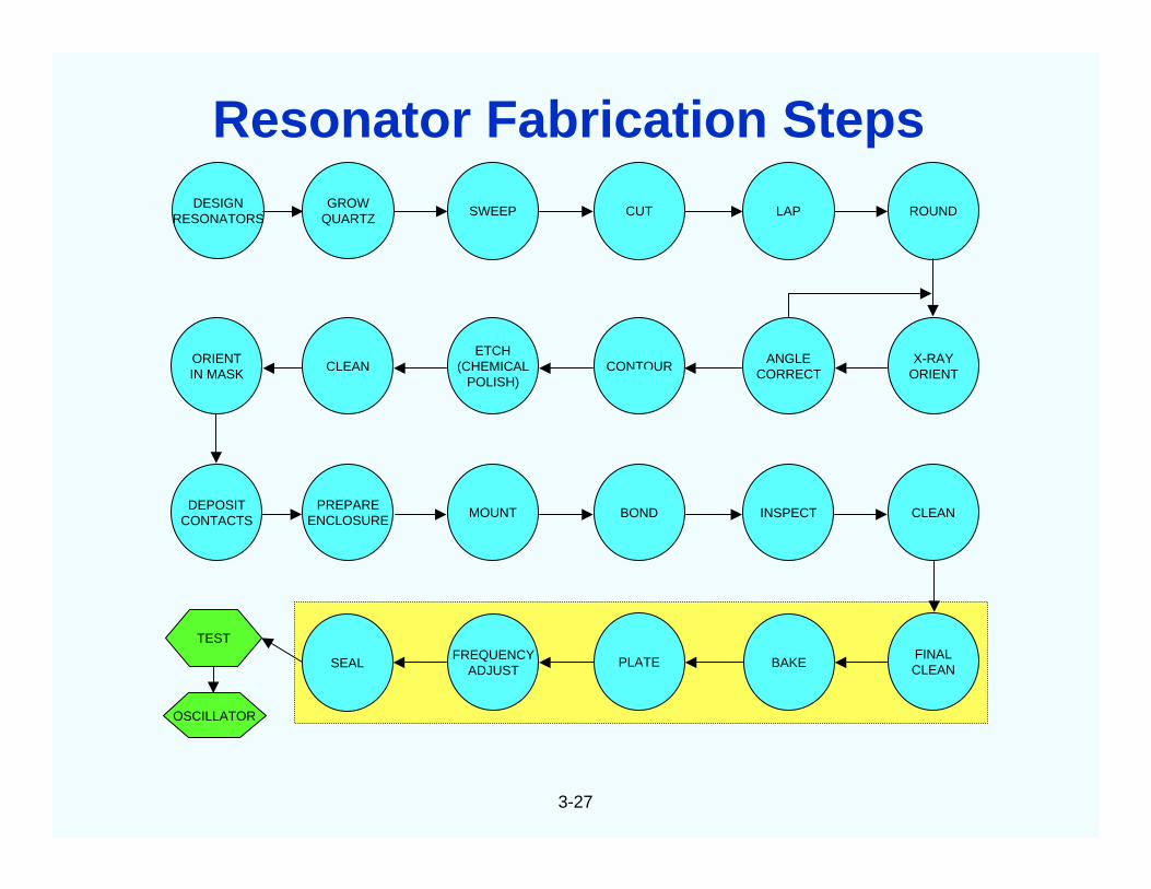
Resonator Fabrication Steps
3-28
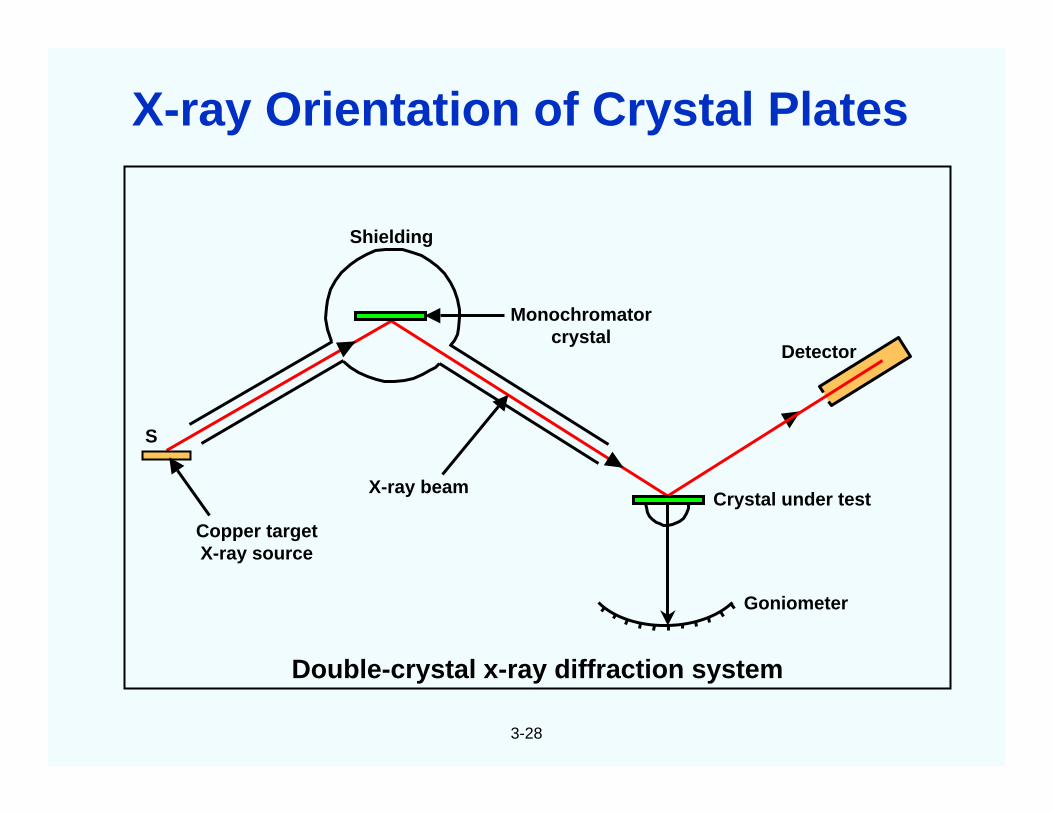
S
Copper targetX-ray source
Shielding
Monochromatorcrystal
Detector
Crystal under test
Double-crystal x-ray diffraction system
Goniometer
X-ray beam
X-ray Orientation of Crystal Plates
3-29
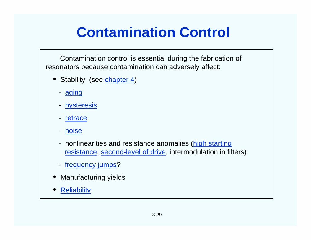
Contamination control is essential during the fabrication ofresonators because contamination can adversely affect:
• Stability (see chapter 4)
- aging
- hysteresis
- retrace
- noise
- nonlinearities and resistance anomalies (high startingresistance, second-level of drive, intermodulation in filters)
- frequency jumps?
• Manufacturing yields
• Reliability
Contamination Control
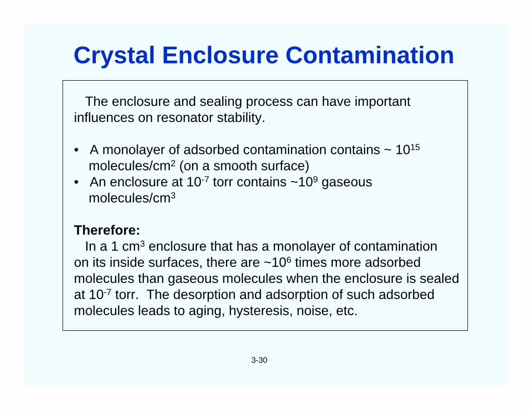
The enclosure and sealing process can have importantinfluences on resonator stability.
• A monolayer of adsorbed contamination contains ~ 1015
molecules/cm2 (on a smooth surface)• An enclosure at 10-7 torr contains ~109 gaseous
molecules/cm3
Therefore:In a 1 cm3 enclosure that has a monolayer of contamination
on its inside surfaces, there are ~106 times more adsorbedmolecules than gaseous molecules when the enclosure is sealedat 10-7 torr. The desorption and adsorption of such adsorbedmolecules leads to aging, hysteresis, noise, etc.
3-30
Crystal Enclosure Contamination
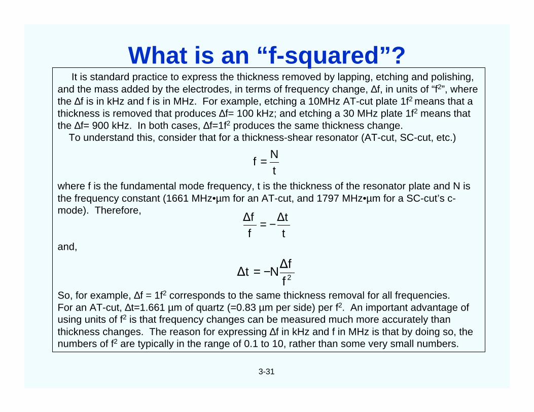
It is standard practice to express the thickness removed by lapping, etching and polishing,and the mass added by the electrodes, in terms of frequency change, ∆f, in units of “f2”, wherethe ∆f is in kHz and f is in MHz. For example, etching a 10MHz AT-cut plate 1f2 means that athickness is removed that produces ∆f= 100 kHz; and etching a 30 MHz plate 1f2 means thatthe ∆f= 900 kHz. In both cases, ∆f=1f2 produces the same thickness change.
To understand this, consider that for a thickness-shear resonator (AT-cut, SC-cut, etc.)
where f is the fundamental mode frequency, t is the thickness of the resonator plate and N isthe frequency constant (1661 MHz•µm for an AT-cut, and 1797 MHz•µm for a SC-cut’s c-mode). Therefore,
and,
So, for example, ∆f = 1f2 corresponds to the same thickness removal for all frequencies.For an AT-cut, ∆t=1.661 µm of quartz (=0.83 µm per side) per f2. An important advantage ofusing units of f2 is that frequency changes can be measured much more accurately thanthickness changes. The reason for expressing ∆f in kHz and f in MHz is that by doing so, thenumbers of f2 are typically in the range of 0.1 to 10, rather than some very small numbers.
3-31
tN
f =
t∆t
f∆f −=
2f∆f
N∆t −=
What is an “f-squared”?
3-32
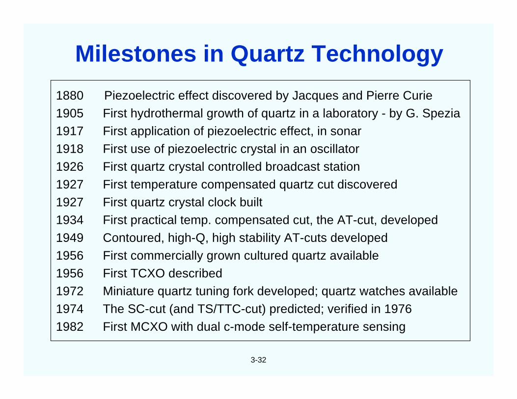
1880 Piezoelectric effect discovered by Jacques and Pierre Curie1905 First hydrothermal growth of quartz in a laboratory - by G. Spezia1917 First application of piezoelectric effect, in sonar1918 First use of piezoelectric crystal in an oscillator1926 First quartz crystal controlled broadcast station1927 First temperature compensated quartz cut discovered1927 First quartz crystal clock built1934 First practical temp. compensated cut, the AT-cut, developed1949 Contoured, high-Q, high stability AT-cuts developed1956 First commercially grown cultured quartz available1956 First TCXO described1972 Miniature quartz tuning fork developed; quartz watches available1974 The SC-cut (and TS/TTC-cut) predicted; verified in 19761982 First MCXO with dual c-mode self-temperature sensing
Milestones in Quartz Technology
3-33
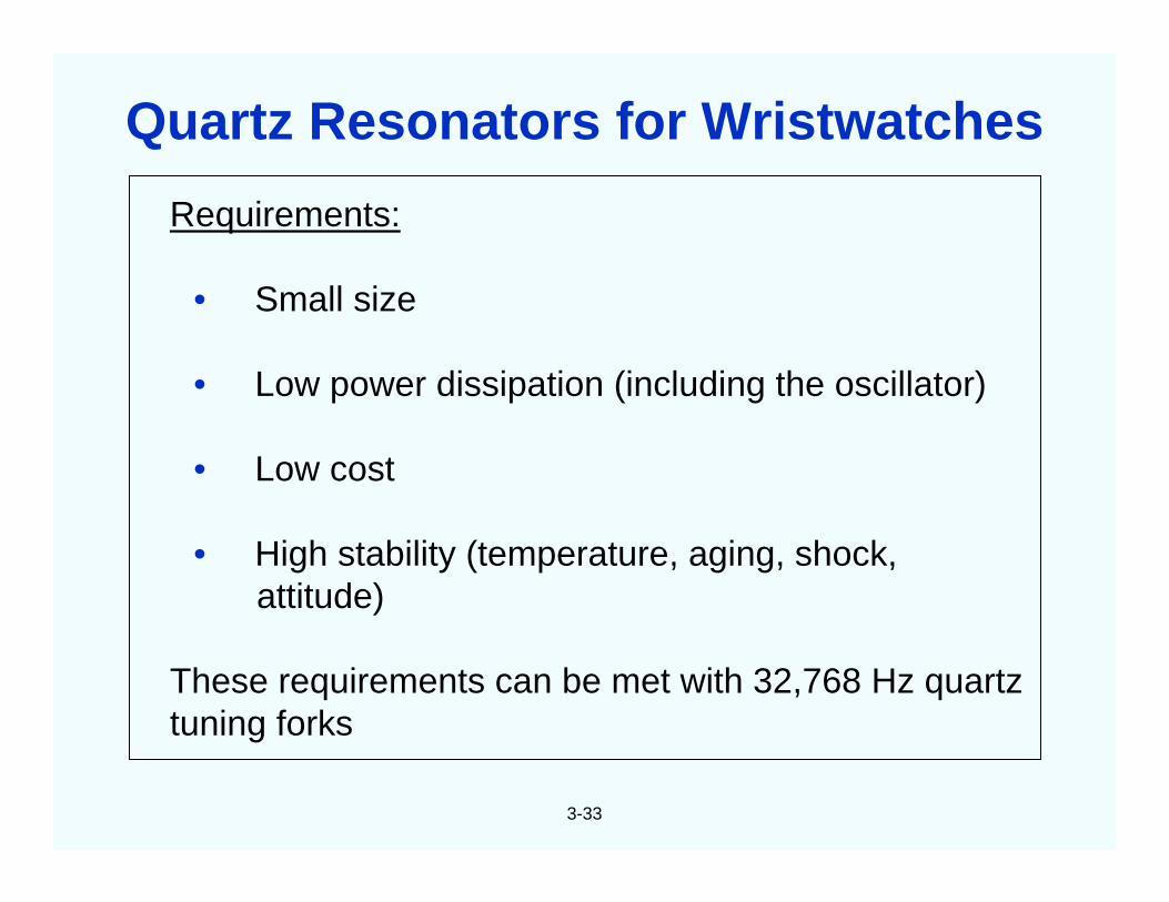
Requirements:
• Small size
• Low power dissipation (including the oscillator)
• Low cost
• High stability (temperature, aging, shock,attitude)
These requirements can be met with 32,768 Hz quartztuning forks
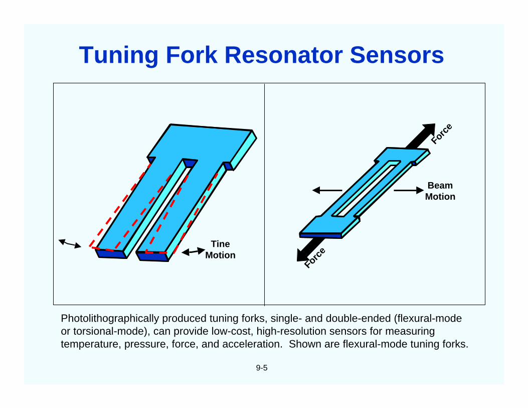
Quartz Resonators for Wristwatches
3-34
32,76816,3848,1924,0962,0481,024
512256128643216
8421
32,768 = 215
• In an analog watch, a stepping motor receivesone impulse per second which advances thesecond hand by 6o, i.e., 1/60th of a circle,every second.
• Dividing 32,768 Hz by two 15 times resultsin 1 Hz.
• The 32,768 Hz is a compromise among size,power requirement (i.e., battery life) andstability.
Why 32,768 Hz?
3-35
Z
YX
Y’
0~50
Y
Z
Xbase
arm
a) natural faces and crystallographic axes of quartz
b) crystallographic orientation of tuning fork c) vibration mode of tuning fork
Quartz Tuning Fork
3-36
Watch Crystal
3-37
In lateral field resonators (LFR): 1. the electrodes are absent from theregions of greatest motion, and 2. varying the orientation of the gap betweenthe electrodes varies certain important resonator properties. Advantages ofLFR are:
• Ability to eliminate undesired modes, e.g., the b-mode in SC-cuts• Potentially higher Q (less damping due to electrodes and mode traps)• Potentially higher stability (less electrode and mode trap effects, smaller C1)
Lateral Field Thickness Field
Lateral Field Resonator
3-38
C
D1
D2
Side view of BVA2
resonator constructionSide and top views of
center plate C
C
Quartzbridge
Electrodeless (BVA) Resonator
4
CHAPTER 4Oscillator Stability
4-1
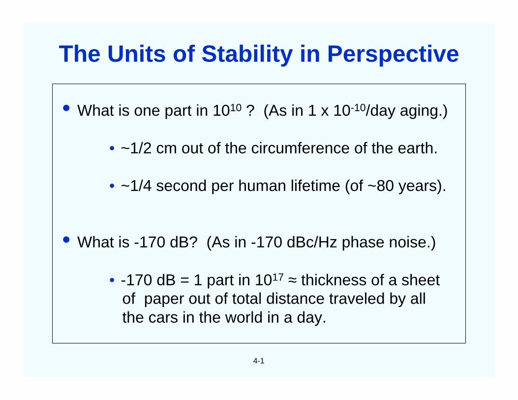
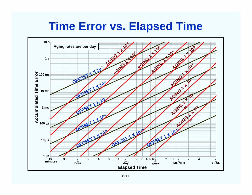
• What is one part in 1010 ? (As in 1 x 10⁻¹⁰/day aging.)
• ~1/2 cm out of the circumference of the earth.
• ~1/4 second per human lifetime (of ~80 years).
• What is -170 dB? (As in -170 dBc/Hz phase noise.)
• -170 dB = 1 part in 1017 ≈ thickness of a sheetof paper out of total distance traveled by allthe cars in the world in a day.
The Units of Stability in Perspective
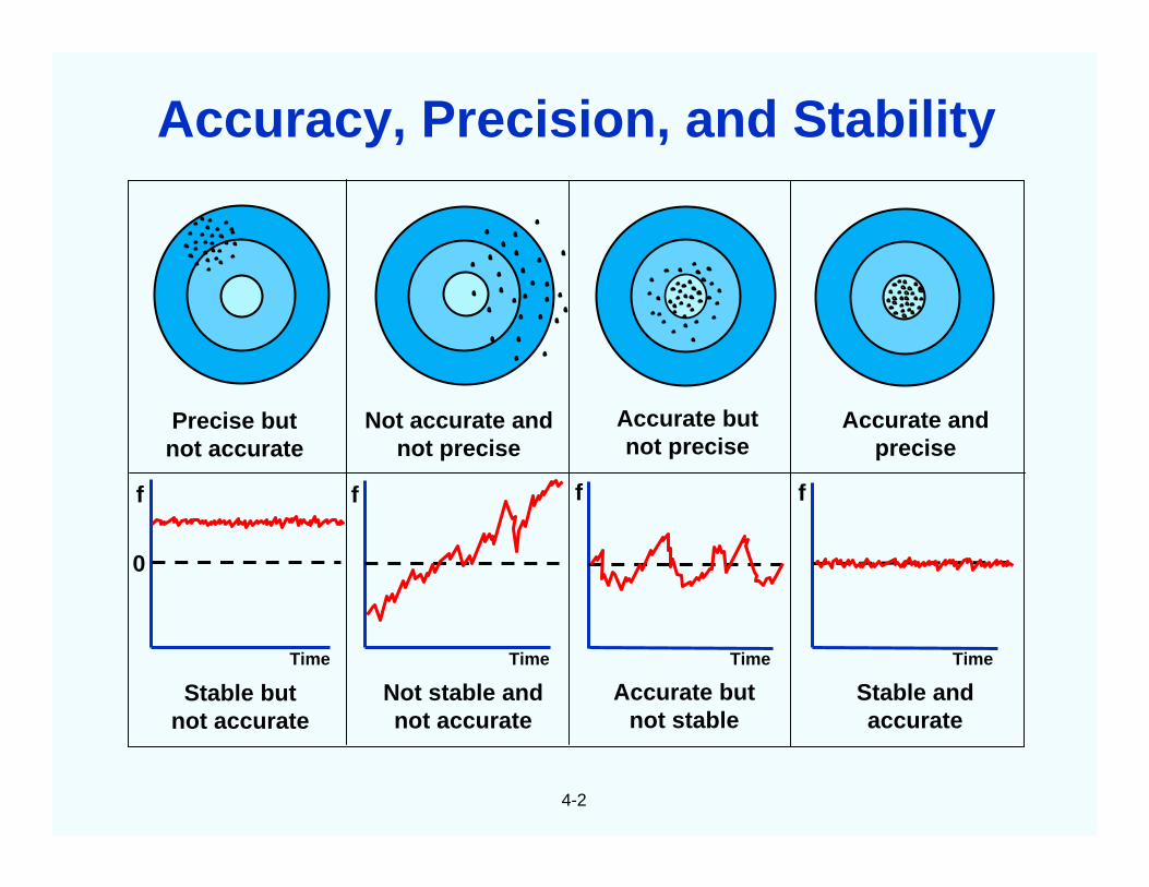
4-2
Precise butnot accurate
Not accurate andnot precise
Accurate butnot precise
Accurate andprecise
Time TimeTimeTime
Stable butnot accurate
Not stable andnot accurate
Accurate butnot stable
Stable andaccurate
0
f fff
Accuracy, Precision, and Stability
4-3
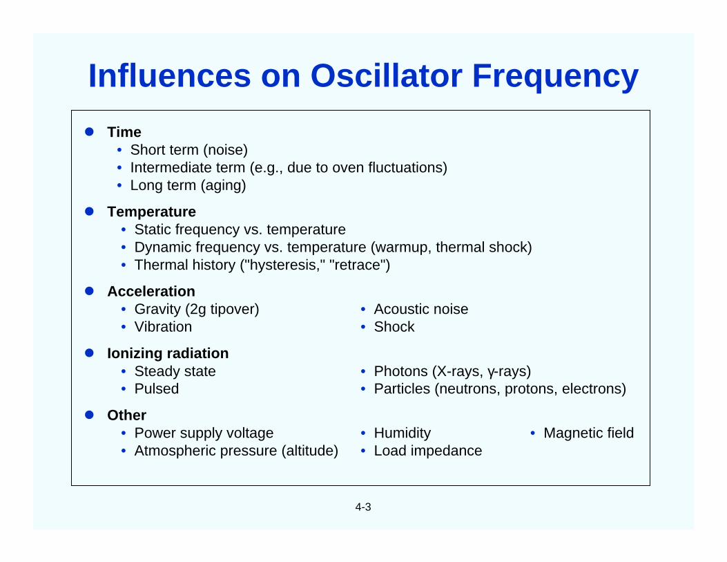
Time• Short term (noise)• Intermediate term (e.g., due to oven fluctuations)• Long term (aging)
Temperature• Static frequency vs. temperature• Dynamic frequency vs. temperature (warmup, thermal shock)• Thermal history ("hysteresis," "retrace")
Other• Power supply voltage • Humidity • Magnetic field• Atmospheric pressure (altitude) • Load impedance
Influences on Oscillator Frequency
4-4
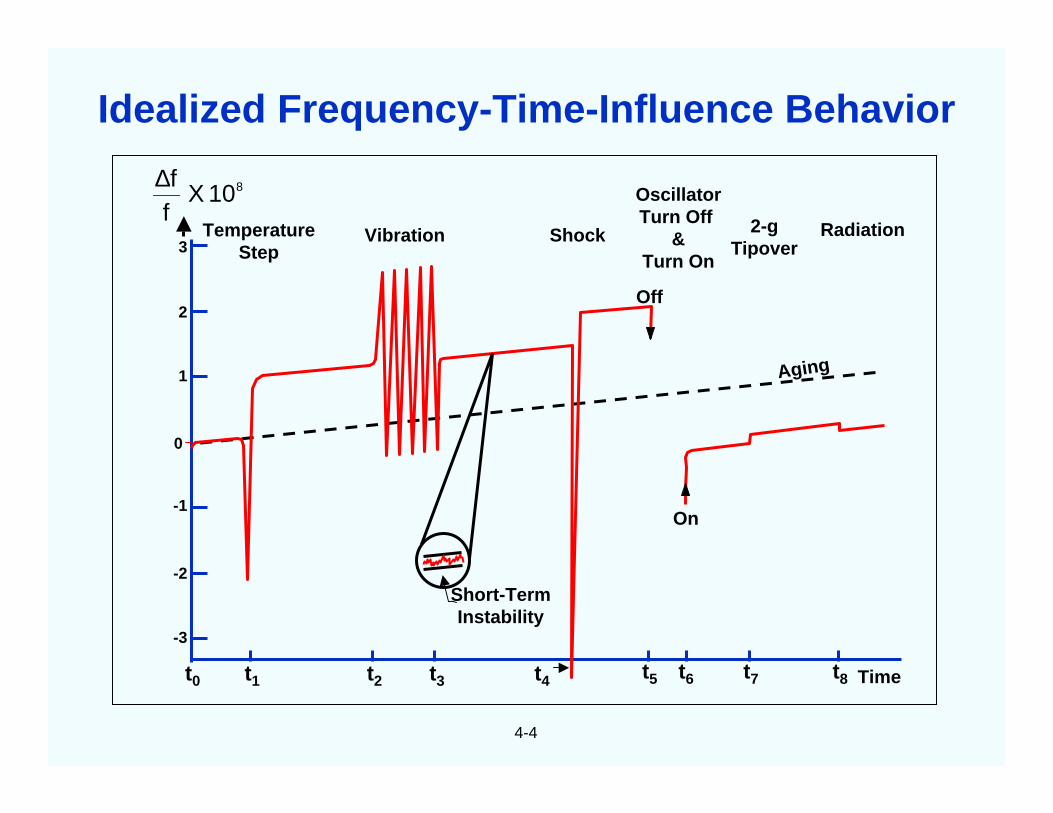
810Xff∆
3
2
1
0
-1
-2
-3
t0 t1 t2 t3 t4
TemperatureStep
Vibration Shock
OscillatorTurn Off
&Turn On
2-gTipover
Radiation
Timet5 t6 t7 t8
Aging
Off
On
Short-TermInstability
Idealized Frequency-Time-Influence Behavior
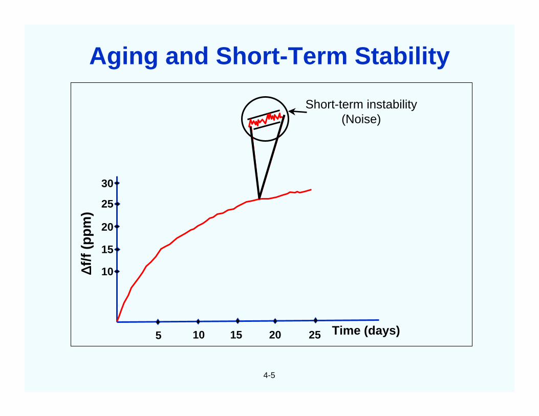
4-5
5 10 15 20 25 Time (days)
Short-term instability(Noise)
∆∆ ∆∆f/f
(pp
m)
30
25
20
15
10
Aging and Short-Term Stability
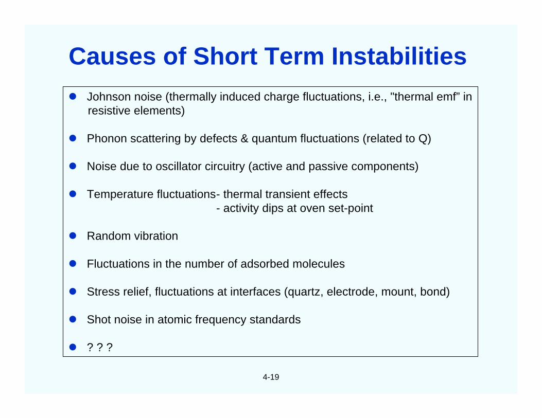
4-6
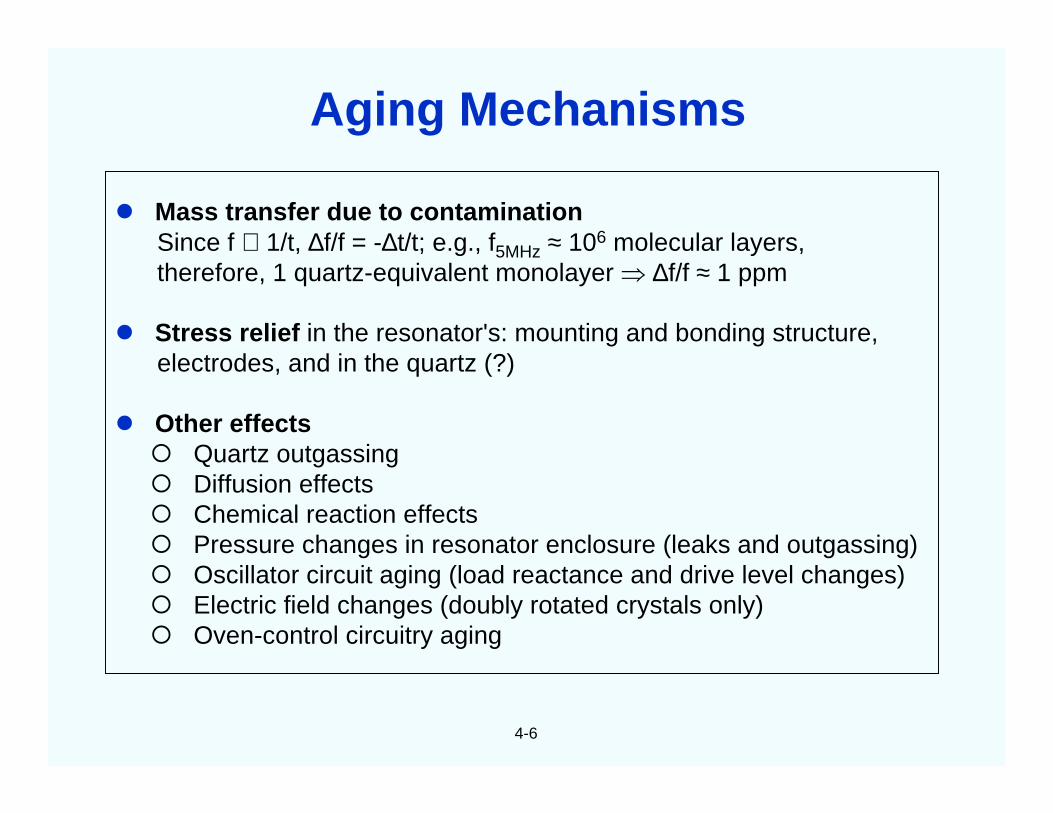
Mass transfer due to contaminationSince f ∝ 1/t, ∆f/f = -∆t/t; e.g., f5MHz ≈ 106 molecular layers,therefore, 1 quartz-equivalent monolayer ⇒ ∆f/f ≈ 1 ppm
Stress relief in the resonator's: mounting and bonding structure,electrodes, and in the quartz (?)
Other effects Quartz outgassing Diffusion effects Chemical reaction effects Pressure changes in resonator enclosure (leaks and outgassing) Oscillator circuit aging (load reactance and drive level changes) Electric field changes (doubly rotated crystals only) Oven-control circuitry aging
Aging Mechanisms
4-7
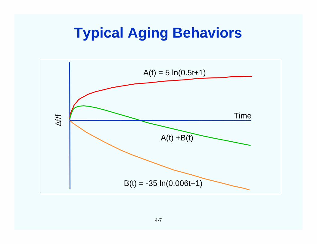
∆f/f
A(t) = 5 ln(0.5t+1)
Time
A(t) +B(t)
B(t) = -35 ln(0.006t+1)
Typical Aging Behaviors
4-8
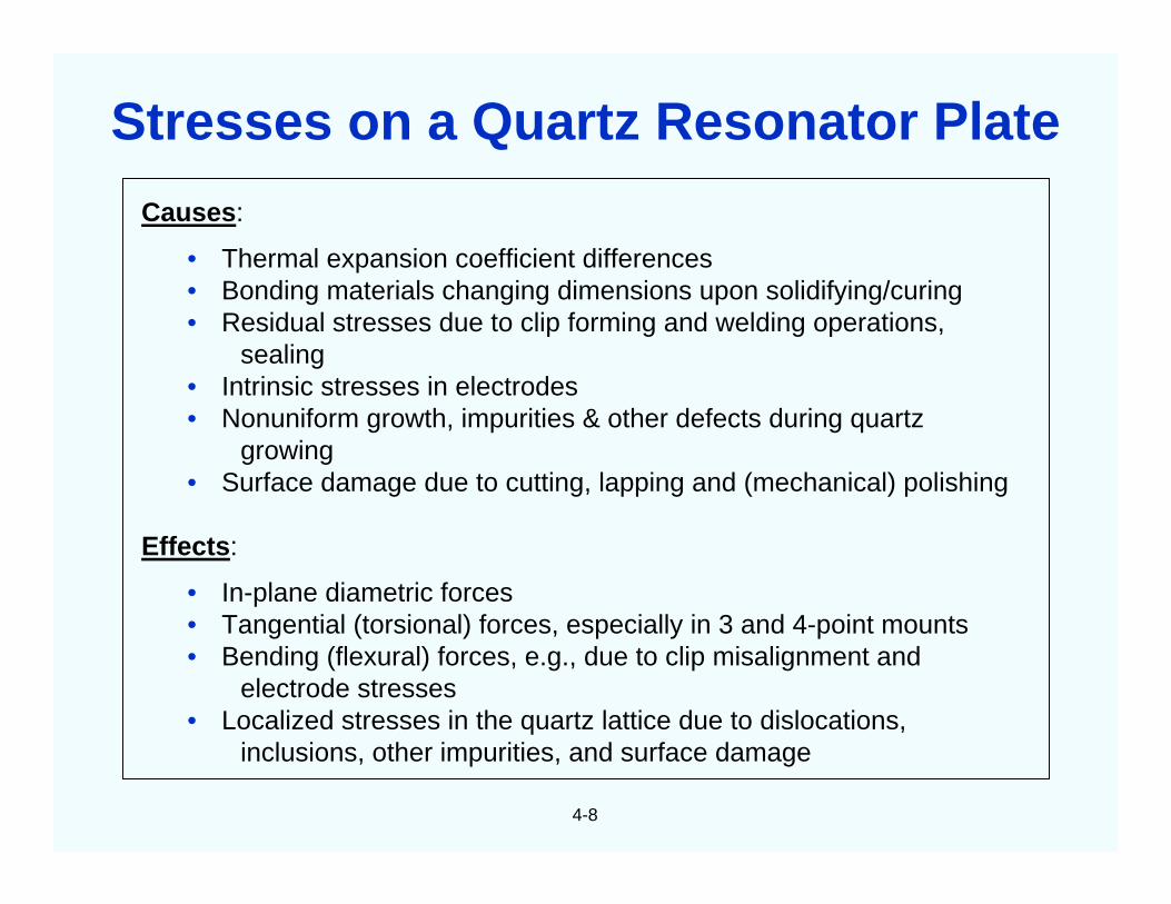
Causes:
• Thermal expansion coefficient differences• Bonding materials changing dimensions upon solidifying/curing• Residual stresses due to clip forming and welding operations,
sealing• Intrinsic stresses in electrodes• Nonuniform growth, impurities & other defects during quartz
growing• Surface damage due to cutting, lapping and (mechanical) polishing
Effects:
• In-plane diametric forces• Tangential (torsional) forces, especially in 3 and 4-point mounts• Bending (flexural) forces, e.g., due to clip misalignment and
electrode stresses• Localized stresses in the quartz lattice due to dislocations,
inclusions, other impurities, and surface damage
Stresses on a Quartz Resonator Plate
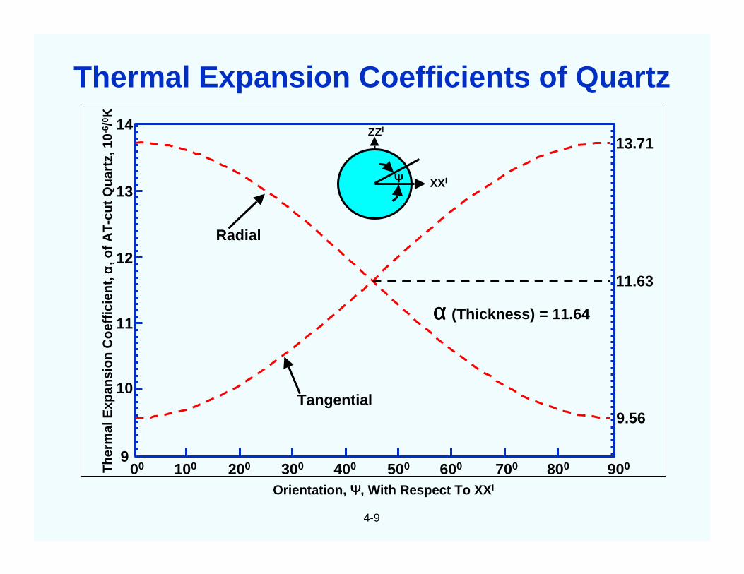
4-9
ΨΨΨΨ XXl
ZZl
13.71
11.63
9.56
00 100 200 300 400 500 600 700 800 900
14
13
12
11
10
9
Radial
Tangential
αααα (Thickness) = 11.64
Orientation, ΨΨΨΨ, With Respect To XXl
Th
erm
alE
xpan
sio
nC
oef
fici
ent,
αα αα,o
fA
T-c
ut
Qu
artz
,10-
6 /0 K
Thermal Expansion Coefficients of Quartz
4-10
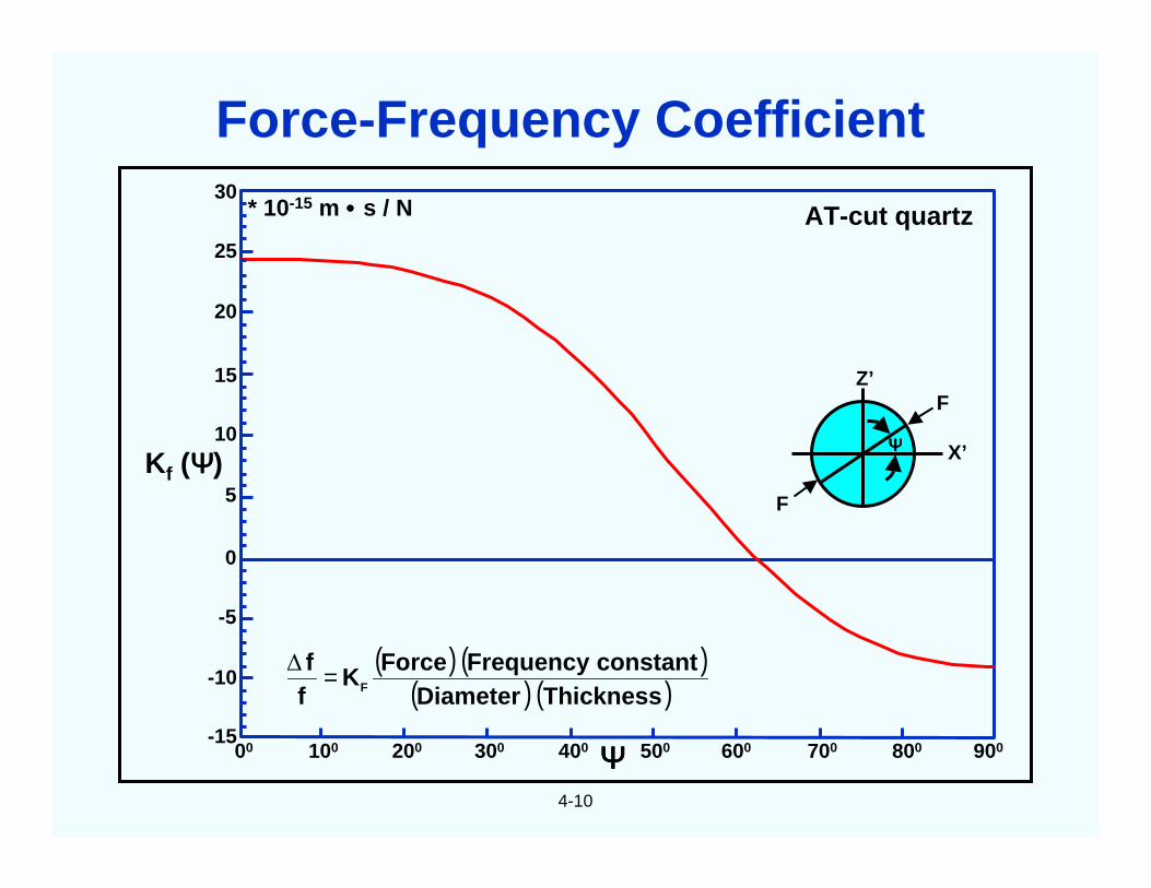
* 10-15 m •••• s / N AT-cut quartz
Z’F
X’
F
30
25
20
15
10
5
0
-5
-10
-1500 100 200 300 400 500 600 700 800 900ΨΨΨΨ
Kf (ΨΨΨΨ)
( ) ( )( ) ( )ThicknessDiameter
constantFrequencyForceK
ff
F=∆
ΨΨΨΨ
Force-Frequency Coefficient
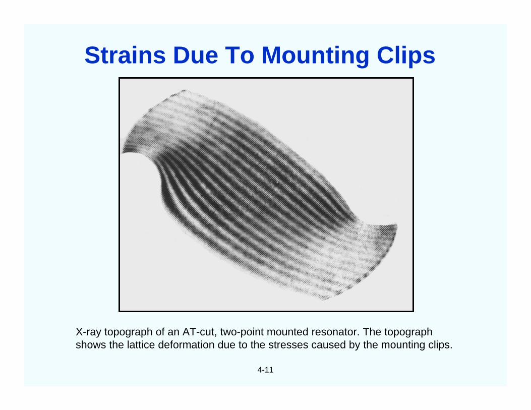
4-11
X-ray topograph of an AT-cut, two-point mounted resonator. The topographshows the lattice deformation due to the stresses caused by the mounting clips.
Strains Due To Mounting Clips
4-12
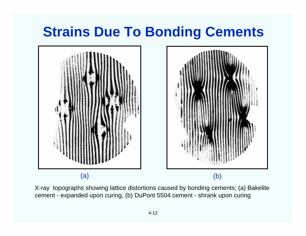
X-ray topographs showing lattice distortions caused by bonding cements; (a) Bakelitecement - expanded upon curing, (b) DuPont 5504 cement - shrank upon curing
(a) (b)
Strains Due To Bonding Cements
4-13
The force-frequency coefficient, KF (ψ), is defined by
Maximum KF (AT-cut) = 24.5 x 10⁻¹⁵ m-s/N at ψ = 0o
Maximum KF (SC-cut) = 14.7 x 10⁻¹⁵ m-s/N at ψ = 44o
As an example, consider a 5 MHz 3rd overtone, 14 mm diameter resonator.Assuming the presence of diametrical forces only, (1 gram = 9.81 x 10⁻³
newtons),
2.9 x 10⁻⁸ per gram for an AT-cut resonator1.7 x 10-8 per gram for an SC-cut resonator
0 at ψ = 61o for an AT-cut resonator, and at ψ = 82o for anSC-cut.
F
F
X’
Z’
( ) ( )( ) ( )ThicknessDiameter
ttanconsFrequencyForceK
ff
F
−=∆
=
Maxf∆f
=
Minf∆f
ΨΨΨΨ
Mounting Force Induced Frequency Change
4-14
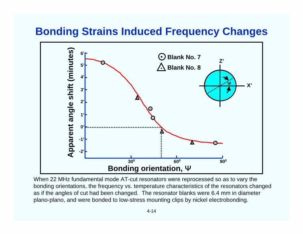
When 22 MHz fundamental mode AT-cut resonators were reprocessed so as to vary thebonding orientations, the frequency vs. temperature characteristics of the resonators changedas if the angles of cut had been changed. The resonator blanks were 6.4 mm in diameterplano-plano, and were bonded to low-stress mounting clips by nickel electrobonding.
Bonding orientation, ΨΨΨΨ
Ap
par
ent
ang
lesh
ift
(min
ute
s)
•
• Blank No. 7
Blank No. 8Z’
X’
6’
5’
4’
3’
2’
1’
0’
-1’
-2’
300 600 900
•
•
•
•
••
•
ΨΨΨΨ
Bonding Strains Induced Frequency Changes
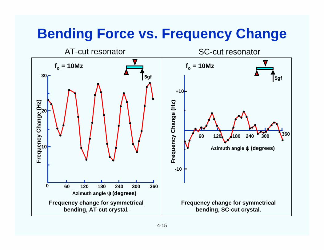
AT-cut resonator SC-cut resonator
4-15
5gf
fo = 10Mz fo = 10Mz
5gf
Fre
qu
ency
Ch
ang
e(H
z)
Fre
qu
ency
Ch
ang
e(H
z)
30
20
10
0 240120 18060 300 360
240120 18060 300 360
+10
-10
Azimuth angle ψψψψ (degrees)
Azimuth angle ψψψψ (degrees)
Frequency change for symmetricalbending, SC-cut crystal.
Frequency change for symmetricalbending, AT-cut crystal.
•
••
•
•
• •
•
•
•
•
•
•
••
•
•
• •
•
•
•
••
•
••
••
•
••
•
••••• •••
••••••••
•••••
••
•••••••
••••••
Bending Force vs. Frequency Change
4-16
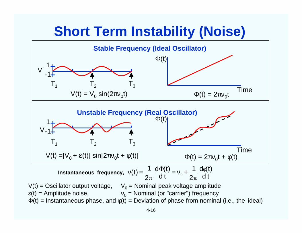
Stable Frequency (Ideal Oscillator)
Unstable Frequency (Real Oscillator)
Time
Φ(t)
Time
Φ(t)
V1-1
T1 T2 T3
1-1
T1 T2 T3
V(t) = V0 sin(2πν0t)
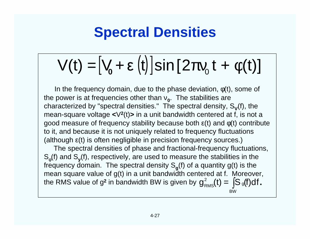
V(t) =[V0 + ε(t)] sin[2πν0t + φ(t)]
Φ(t) = 2πν0t
Φ(t) = 2πν0t + φ(t)
V(t) = Oscillator output voltage, V0 = Nominal peak voltage amplitudeε(t) = Amplitude noise, ν0 = Nominal (or "carrier") frequencyΦ(t) = Instantaneous phase, and φ(t) = Deviation of phase from nominal (i.e., the ideal)
td)t(d
21=
td)t(d
21=)t( 0
φ+ννπ
Φ
πfrequency,ousInstantane
V
Short Term Instability (Noise)
4-17
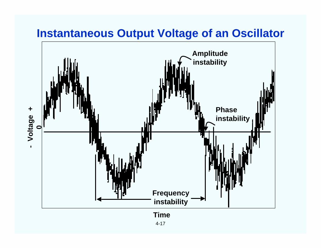
Amplitudeinstability
Frequencyinstability
Phaseinstability
-V
olt
age
+0
Time
Instantaneous Output Voltage of an Oscillator
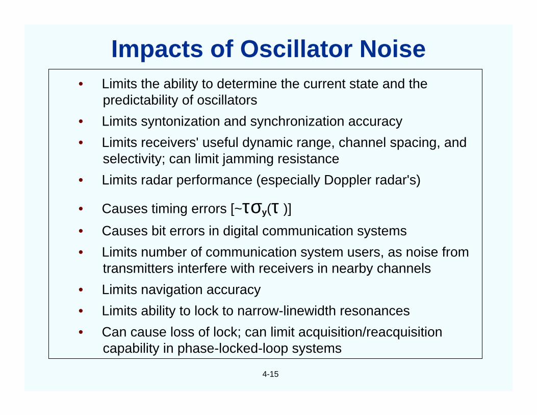
• Limits the ability to determine the current state and thepredictability of oscillators
• Limits syntonization and synchronization accuracy
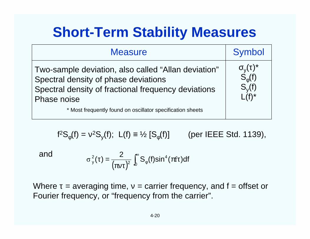
Where τ = averaging time, ν = carrier frequency, and f = offset orFourier frequency, or “frequency from the carrier”.
( ) )df((f)sinS2
)( 4
022y τπ
πντ=τ ∫
∞
φ fσ
Short-Term Stability Measures
4-21
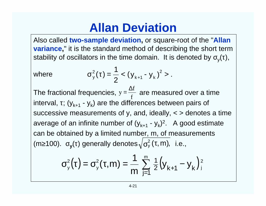
Also called two-sample deviation, or square-root of the "Allanvariance," it is the standard method of describing the short termstability of oscillators in the time domain. It is denoted by σy(τ),
where
The fractional frequencies, are measured over a time
interval, τ; (yk+1 - yk) are the differences between pairs ofsuccessive measurements of y, and, ideally, < > denotes a timeaverage of an infinite number of (yk+1 - yk)2. A good estimatecan be obtained by a limited number, m, of measurements
(m≥100). σy(τ) generally denotes i.e.,,)m,(2y τσ
.)y-y(21
=)( 2k+1k
2y ><τσ
( ) ( ) 2j
m2y
2y k1k
1j21 yy
m1
)m,( −=τσ=τσ +=∑
f
fy
∆=
Allan Deviation
4-22
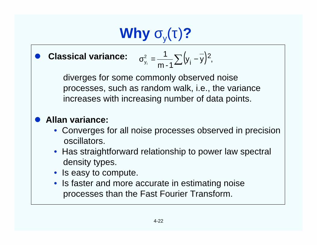
Classical variance:
diverges for some commonly observed noiseprocesses, such as random walk, i.e., the varianceincreases with increasing number of data points.
Allan variance:• Converges for all noise processes observed in precision
oscillators.• Has straightforward relationship to power law spectral
density types.• Is easy to compute.• Is faster and more accurate in estimating noise
processes than the Fast Fourier Transform.
( ) ,yy1-m
1 2i
2yi ∑ −=σ
Why σy(τ)?
4-23
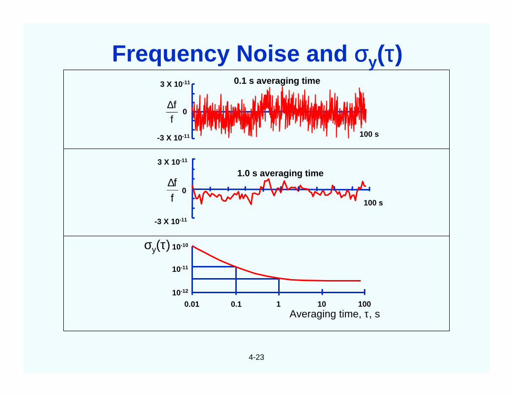
0.1 s averaging time3 X 10-11
0
-3 X 10-11
ff∆
100 s
1.0 s averaging time3 X 10-11
0
-3 X 10-11
ff∆
100 s
0.01 0.1 1 10 100Averaging time, τ, s
10-10
10-11
10-12
σy(τ)
Frequency Noise and σσσσy(ττττ)
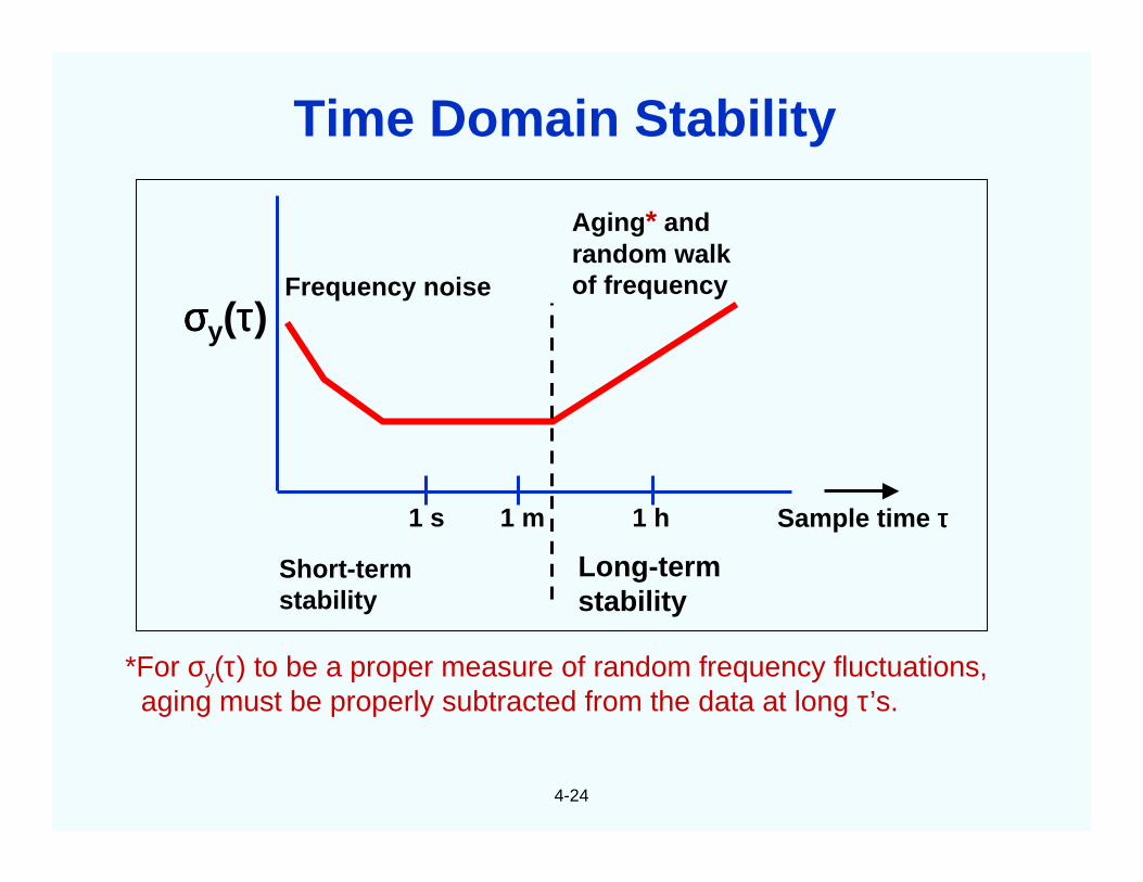
4-24
*For σy(τ) to be a proper measure of random frequency fluctuations,aging must be properly subtracted from the data at long τ’s.
σσσσy(ττττ)Frequency noise
Aging* andrandom walkof frequency
Short-termstability
Long-termstability
1 s 1 m 1 h Sample time ττττ
Time Domain Stability
4-25
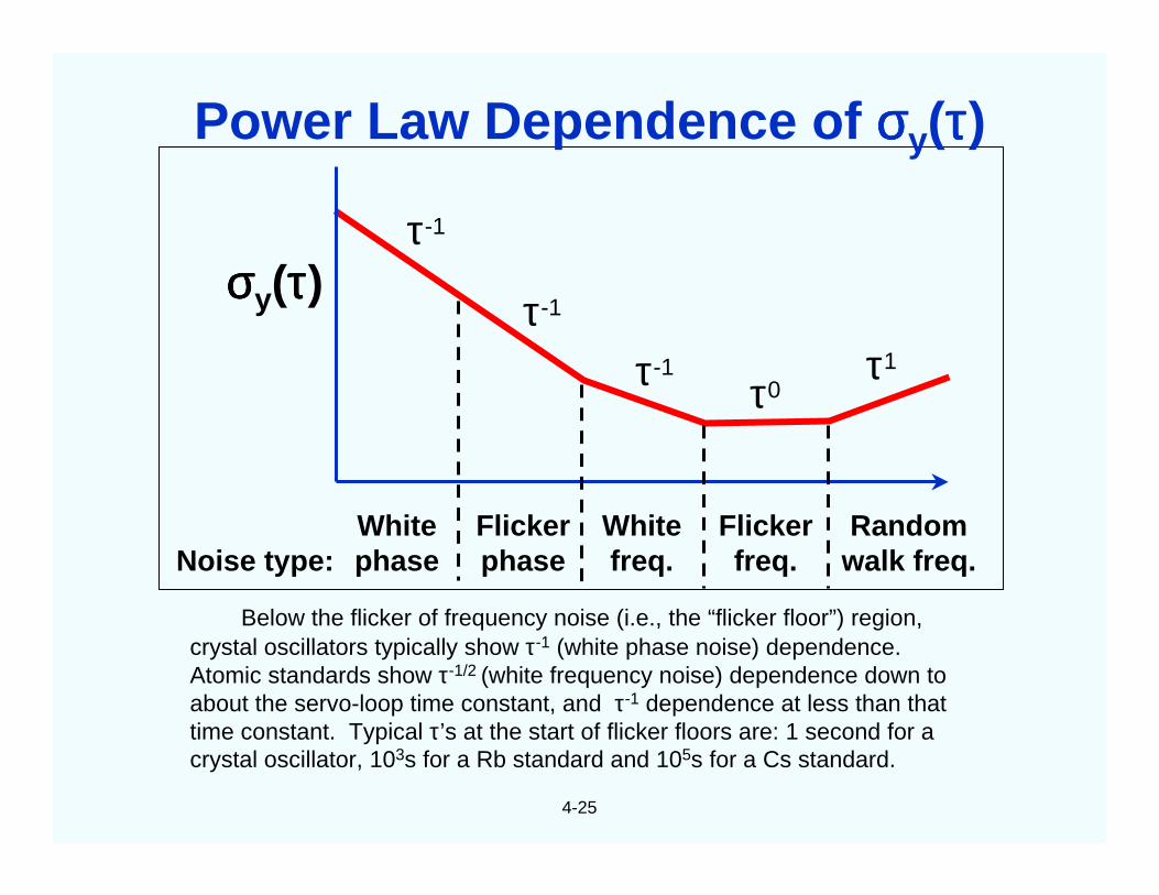
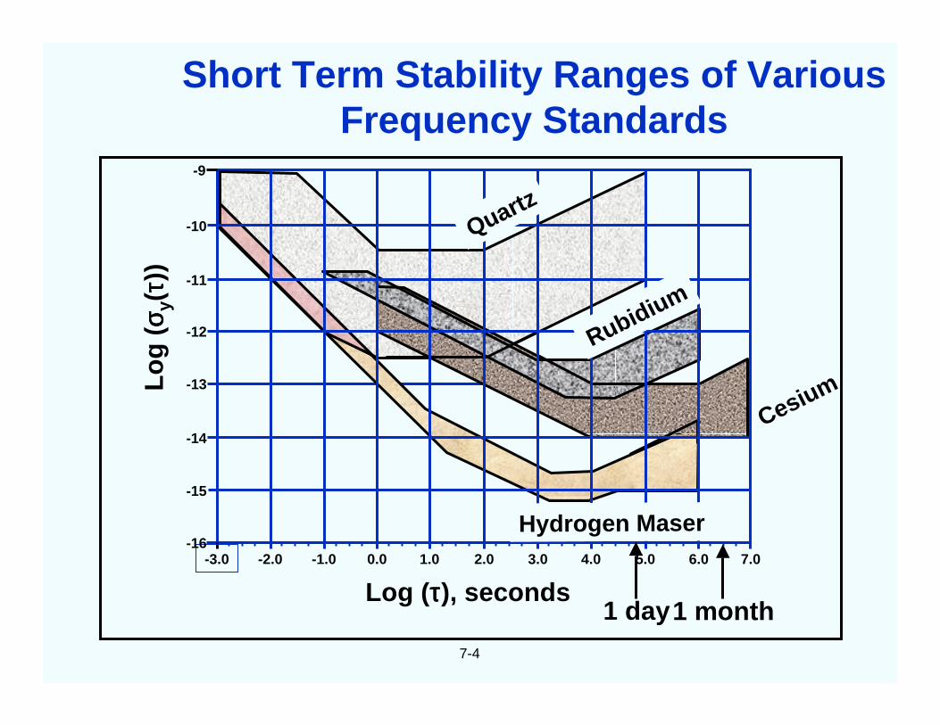
Below the flicker of frequency noise (i.e., the “flicker floor”) region,crystal oscillators typically show τ-1 (white phase noise) dependence.Atomic standards show τ-1/2 (white frequency noise) dependence down toabout the servo-loop time constant, and τ-1 dependence at less than thattime constant. Typical τ’s at the start of flicker floors are: 1 second for acrystal oscillator, 103s for a Rb standard and 105s for a Cs standard.
σσσσy(ττττ)τ-1
τ-1
τ0
Noise type:Whitephase
Flickerphase
Whitefreq.
Flickerfreq.
Randomwalk freq.
τ-1 τ1
Power Law Dependence of σσσσy(ττττ)
4-26
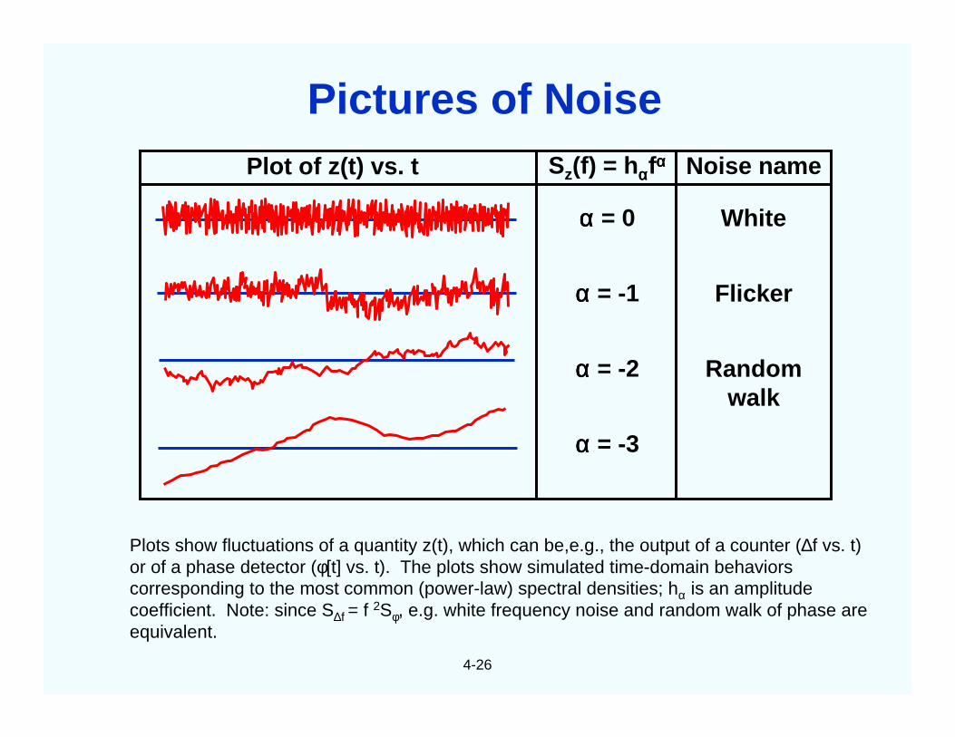
Plots show fluctuations of a quantity z(t), which can be,e.g., the output of a counter (∆f vs. t)or of a phase detector (φ[t] vs. t). The plots show simulated time-domain behaviorscorresponding to the most common (power-law) spectral densities; hα is an amplitudecoefficient. Note: since S∆f = f 2Sφ, e.g. white frequency noise and random walk of phase areequivalent.
Sz(f) = hααααfαααα
αααα = 0
αααα = -1
αααα = -2
αααα = -3
Noise name
White
Flicker
Randomwalk
Plot of z(t) vs. t
Pictures of Noise
4-27
In the frequency domain, due to the phase deviation, φ(t), some ofthe power is at frequencies other than ν0. The stabilities arecharacterized by "spectral densities." The spectral density, SV(f), themean-square voltage <V2(t)> in a unit bandwidth centered at f, is not agood measure of frequency stability because both ε(t) and φ(t) contributeto it, and because it is not uniquely related to frequency fluctuations(although ε(t) is often negligible in precision frequency sources.)
The spectral densities of phase and fractional-frequency fluctuations,Sφ(f) and Sy(f), respectively, are used to measure the stabilities in thefrequency domain. The spectral density Sg(f) of a quantity g(t) is themean square value of g(t) in a unit bandwidth centered at f. Moreover,the RMS value of g2 in bandwidth BW is given by
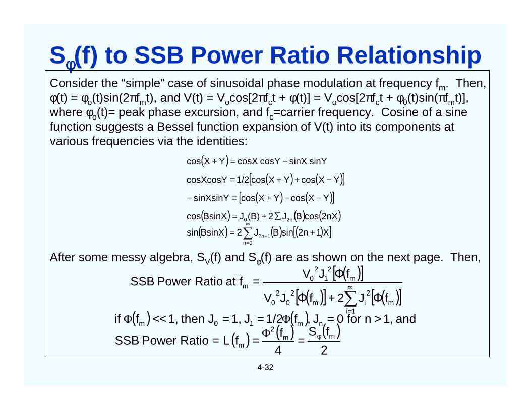
Consider the “simple” case of sinusoidal phase modulation at frequency fm. Then,φ(t) = φo(t)sin(2πfmt), and V(t) = Vocos[2πfct + φ(t)] = Vocos[2πfct + φ0(t)sin(πfmt)],where φo(t)= peak phase excursion, and fc=carrier frequency. Cosine of a sinefunction suggests a Bessel function expansion of V(t) into its components atvarious frequencies via the identities:
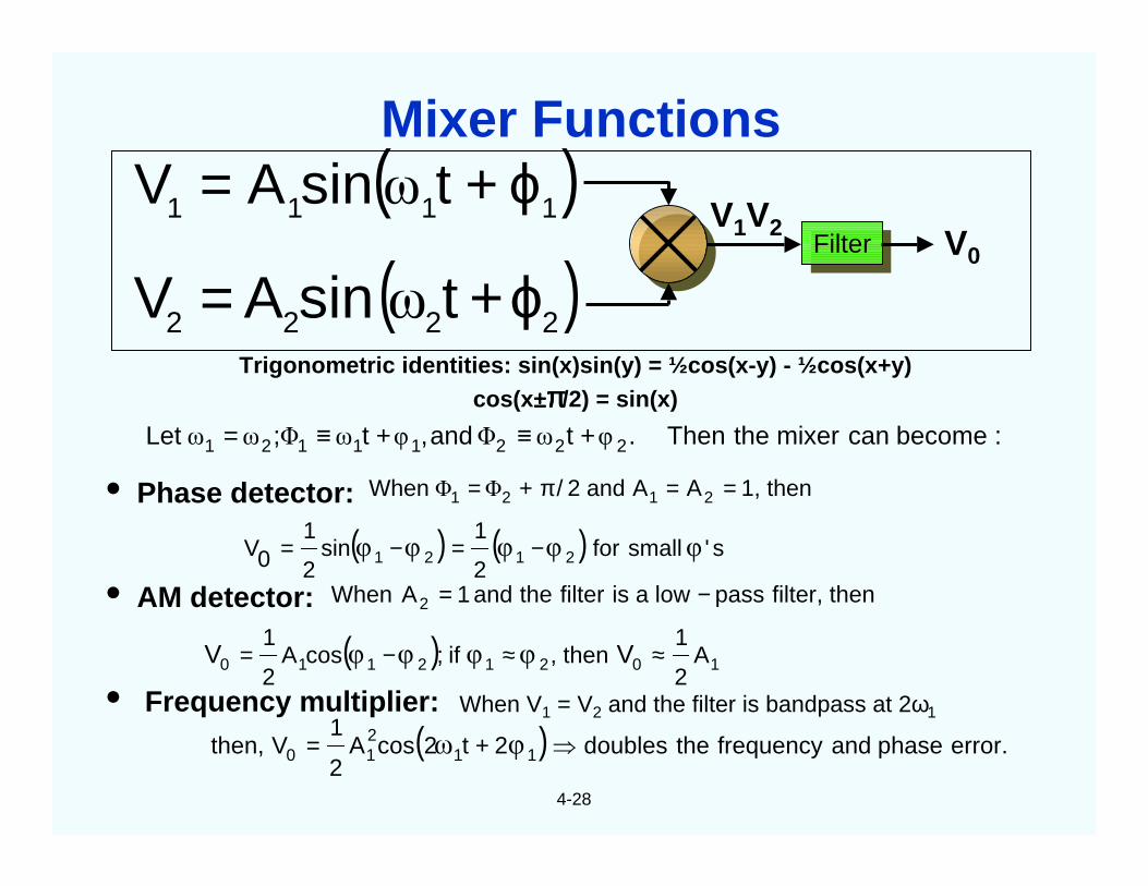
After some messy algebra, SV(f) and Sφ(f) are as shown on the next page. Then,
( )( ) ( )[ ]
( ) ( )[ ]( ) ( ) ( )
( ) ( ) ( )[ ]X12nsinBJ2BsinXsin
2nXcosBJ2(B)JBsinXcos
YXcosYXcossinXsinY
YXcosYXcos1/2cosXcosY
sinYsinXcosYcosXYXcos
12n0n
2n0
+=
∑+=
−−+=−
−++=
−=+
+
∞
=∑
( )[ ]( )[ ] ( )[ ]∑
∞
=
+=
1im
2im
20
20
m2
12
0m
fΦJ2fΦJV
fΦJVfatRatioPowerSSB
( ) ( )( ) ( ) ( )
2
fS
4f
fRatioPowerSSB
and1,nfor0J,f1/2J1,Jthen1,fifmm
2
m
nm10m
φ===
>===<<Φ
ΦΦ
L
Sφφφφ(f) to SSB Power Ratio Relationship
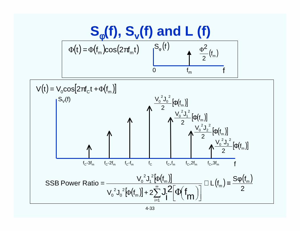
4-33
0 fm f
( ) ( ) ( )tf2cosft mm π=ΦΦ( )fS
φ ( )mf2
2Φ
( ) ( )[ ]mC0 ftf2cosVtV Φ+π=
( )[ ]( )[ ]
( ) ( )2fSφ
f2fJV
fJVRatioPowerSSB m
m
1im
20
20
m2
12
0
mf2iJ
≡≅
+
=∑∞
=
LΦΦ
Φ
SV(f)
fC-3fm fC-2fm fC-fm fC fC+fm fC+2fm fC+3fm f
( )[ ]m
20
20 fΦ2JV
( )[ ]m
21
20 fΦ2JV
( )[ ]m
22
20 fΦ2JV
( )[ ]m
23
20 fΦ2JV
Sφφφφ(f), Sv(f) and L (f)
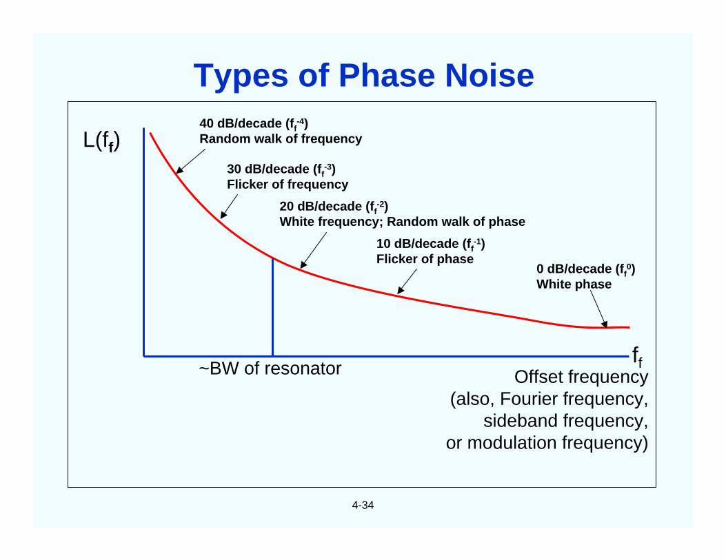
4-34
L(ff)40 dB/decade (ff
-4)Random walk of frequency
30 dB/decade (ff-3)
Flicker of frequency
20 dB/decade (ff-2)
White frequency; Random walk of phase
10 dB/decade (ff-1)
Flicker of phase0 dB/decade (ff
0)White phase
ff~BW of resonator Offset frequency(also, Fourier frequency,
sideband frequency,or modulation frequency)
Types of Phase Noise
4-35
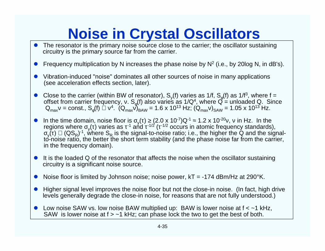
The resonator is the primary noise source close to the carrier; the oscillator sustainingcircuitry is the primary source far from the carrier.
Frequency multiplication by N increases the phase noise by N2 (i.e., by 20log N, in dB's).
Vibration-induced "noise" dominates all other sources of noise in many applications(see acceleration effects section, later).
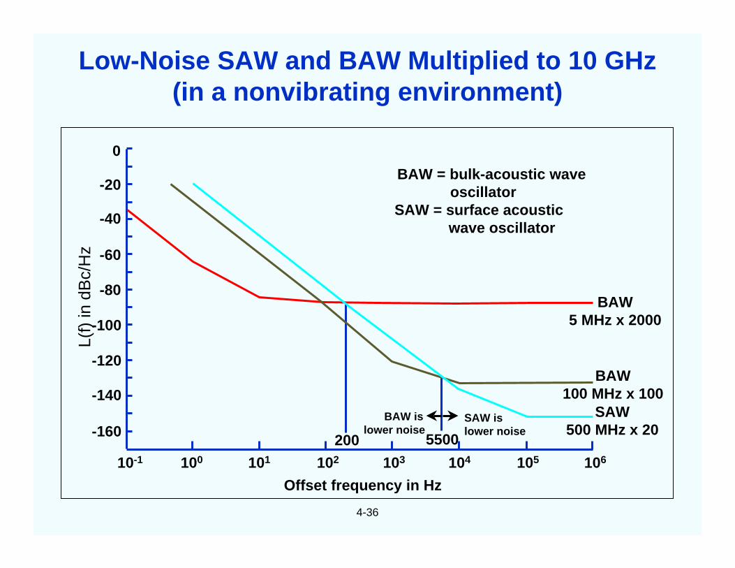
Close to the carrier (within BW of resonator), Sy(f) varies as 1/f, Sφ(f) as 1/f3, where f =offset from carrier frequency, ν. Sφ(f) also varies as 1/Q4, where Q = unloaded Q. SinceQmaxν = const., Sφ(f) ∝ ν 4. (Qmaxν)BAW = 1.6 x 10¹³ Hz; (Qmaxν)SAW = 1.05 x 10¹³ Hz.
In the time domain, noise floor is σy(τ) ≥ (2.0 x 10⁻⁷)Q-1 ≈ 1.2 x 10⁻²⁰ν, ν in Hz. In theregions where σy(τ) varies as τ-1 and τ-1/2 (τ-1/2 occurs in atomic frequency standards),σy(τ) ∝ (QSR)-1, where SR is the signal-to-noise ratio; i.e., the higher the Q and the signal-to-noise ratio, the better the short term stability (and the phase noise far from the carrier,in the frequency domain).
It is the loaded Q of the resonator that affects the noise when the oscillator sustainingcircuitry is a significant noise source.
Noise floor is limited by Johnson noise; noise power, kT = -174 dBm/Hz at 290°K.
Higher signal level improves the noise floor but not the close-in noise. (In fact, high drivelevels generally degrade the close-in noise, for reasons that are not fully understood.)
Low noise SAW vs. low noise BAW multiplied up: BAW is lower noise at f < ~1 kHz,SAW is lower noise at f > ~1 kHz; can phase lock the two to get the best of both.
Noise in Crystal Oscillators
4-36
Offset frequency in Hz
0
-20
-40
-60
-80
-100
-120
-140
-160
10-1 100 101 102 103 104 105 106
L(f)
indB
c/H
z
BAW = bulk-acoustic waveoscillator
SAW = surface acousticwave oscillator
BAW islower noise
SAW islower noise
200 5500
BAW5 MHz x 2000
BAW100 MHz x 100
SAW500 MHz x 20
Low-Noise SAW and BAW Multiplied to 10 GHz(in a nonvibrating environment)
4-37
0
-20
-40
-60
-80
-100
-120
-140
-160
10-1 100 101 102 103 104 105 106
500 MHz x 20
100 MHz x 100
BAW and SAW
5 MHz x 2000 BAW
Offset frequency in Hz
L(f
)in
dB
c/H
z
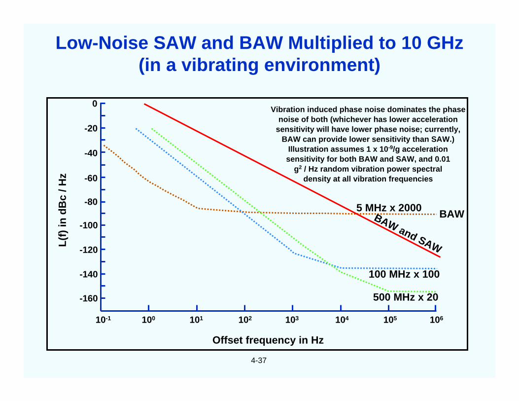
Vibration induced phase noise dominates the phasenoise of both (whichever has lower acceleration
sensitivity will have lower phase noise; currently,BAW can provide lower sensitivity than SAW.)
Illustration assumes 1 x 10⁻⁹/g accelerationsensitivity for both BAW and SAW, and 0.01
g2 / Hz random vibration power spectraldensity at all vibration frequencies
Low-Noise SAW and BAW Multiplied to 10 GHz(in a vibrating environment)
4-38
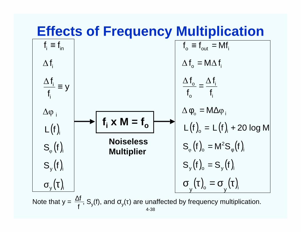
fi x M = fo
Note that y = , Sy(f), and σy(τ) are unaffected by frequency multiplication.∆ff
NoiselessMultiplier
( )( )( )( )iy
iy
i
i
i
i
i
i
ini
fS
fS
f
yff
f
ff
τσ
≡
≡
φ
∆φ
∆
∆
L ( ) ( )( ) ( )( ) ( )( ) ( )
io
iyoy
i2
o
io
i
i
i
o
o
io
iouto
yy
fSfS
fSMfS
Mlog20ff
M
ff
ff
fMf
Mfff
τσ=τσ
=
=
+=
∆=φ
=
=
=≡
φφ
o φ∆
∆∆
∆∆
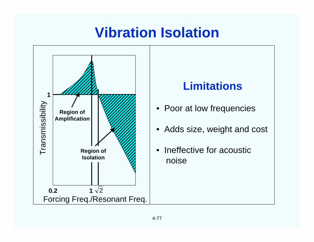
LL
Effects of Frequency Multiplication
4-39
The short term stabilities of TCXOs are temperature (T) dependent, and are generallyworse than those of OCXOs, for the following reasons:
• The slope of the TCXO crystal’s frequency (f) vs. T varies with T. For example,the f vs. T slope may be near zero at ~20oC, but it will be ~1ppm/oC at the T extremes. Tfluctuations will cause small f fluctuations at laboratory ambient T’s, so the stability can begood there, but millidegree fluctuations will cause ~10-9 f fluctuations at the T extremes. TheTCXO’s f vs. T slopes also vary with T; the zeros and maxima can be at any T, and themaximum slopes can be on the order of 1 ppm/oC.
• AT-cut crystals’ thermal transient sensitivity makes the effects of T fluctuationsdepend not only on the T but also on the rate of change of T (whereas the SC-cut crystalstypically used in precision OCXOs are insensitive to thermal transients). Under changing Tconditions, the T gradient between the T sensor (thermistor) and the crystal will aggravate theproblems.
• TCXOs typically use fundamental mode AT-cut crystals which have lower Q andlarger C1 than the crystals typically used in OCXOs. The lower Q makes the crystals inherentlynoisier, and the larger C1 makes the oscillators more susceptible to circuitry noise.
• AT-cut crystals’ f vs. T often exhibit activity dips (see “Activity Dips” later in thischapter). At the T’s where the dips occur, the f vs. T slope can be very high, so the noise dueto T fluctuations will also be very high, e.g., 100x degradation of σy(τ) and 30 dB degradation ofphase noise are possible. Activity dips can occur at any T.
TCXO Noise
4-40
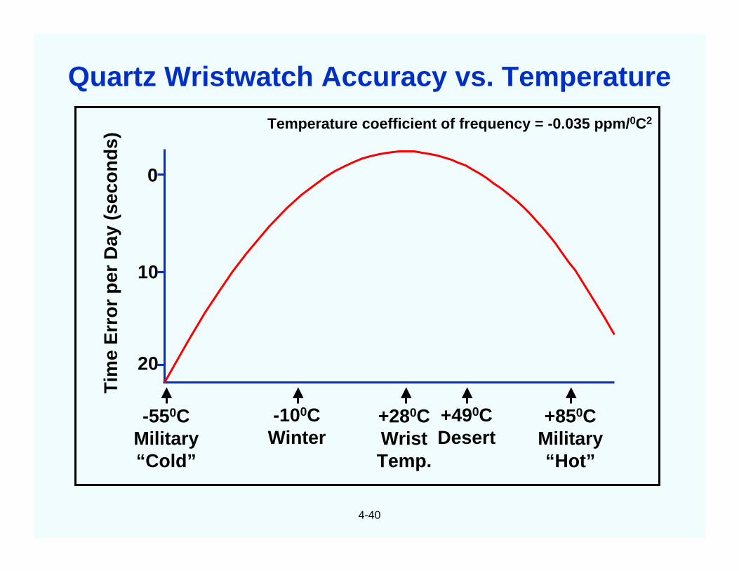
Temperature coefficient of frequency = -0.035 ppm/0C2T
ime
Err
or
per
Day
(sec
on
ds)
-550CMilitary“Cold”
-100CWinter
+280CWristTemp.
+490CDesert
+850CMilitary“Hot”
0
10
20
Quartz Wristwatch Accuracy vs. Temperature
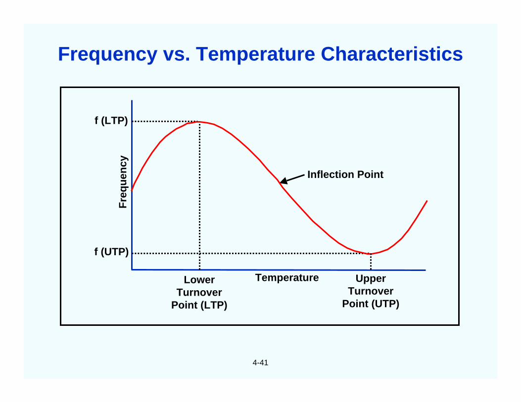
4-41
Inflection Point
TemperatureLowerTurnover
Point (LTP)
UpperTurnover
Point (UTP)
f (UTP)
f (LTP)F
req
uen
cy
Frequency vs. Temperature Characteristics
4-42
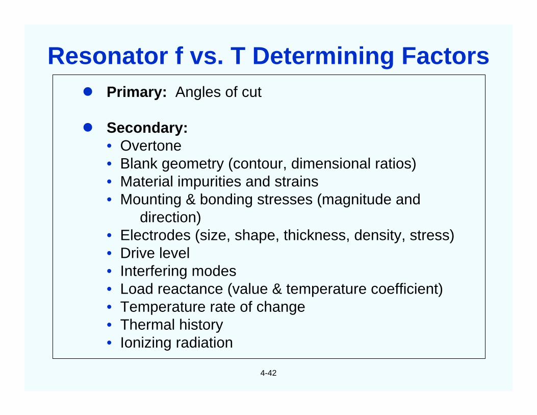
Primary: Angles of cut
Secondary:• Overtone• Blank geometry (contour, dimensional ratios)• Material impurities and strains• Mounting & bonding stresses (magnitude and
direction)• Electrodes (size, shape, thickness, density, stress)• Drive level• Interfering modes• Load reactance (value & temperature coefficient)• Temperature rate of change• Thermal history• Ionizing radiation
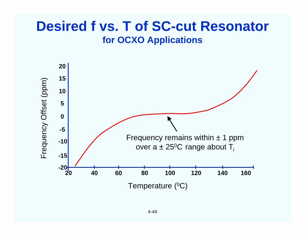
Frequency remains within ± 1 ppmover a ± 250C range about Ti
Temperature (0C)
20
15
10
5
0
-5
-10
-15
-2020 40 60 80 100 120 140 160
Desired f vs. T of SC-cut Resonatorfor OCXO Applications
4-45
A comparative table for AT and other non-thermal-transient compensated cuts of oscillatorswould not be meaningful because the dynamic f vs. T effects would generally dominate thestatic f vs. T effects.
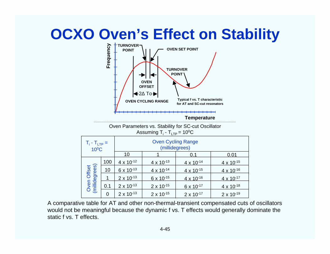
Oven Parameters vs. Stability for SC-cut OscillatorAssuming Ti - TLTP = 100C
Ti - TLTP =100C
Ove
nO
ffset
(mill
ideg
rees
)
Oven Cycling Range(millidegrees)
10
4 x 10-12
6 x 10-13
2 x 10-13
2 x 10-13
2 x 10-13
1
4 x 10-13
4 x 10-14
6 x 10-15
2 x 10-15
2 x 10-15
0.1
4 x 10-14
4 x 10-15
4 x 10-16
6 x 10-17
2 x 10-17
0.01
4 x 10-15
4 x 10-16
4 x 10-17
4 x 10-18
2 x 10-19
100
10
1
0.1
0
TURNOVERPOINT
OVEN SET POINTTURNOVER
POINT
OVENOFFSET
2∆ To
OVEN CYCLING RANGE Typical f vs. T characteristicfor AT and SC-cut resonators
Fre
qu
ency
Temperature
OCXO Oven’s Effect on Stability
4-46
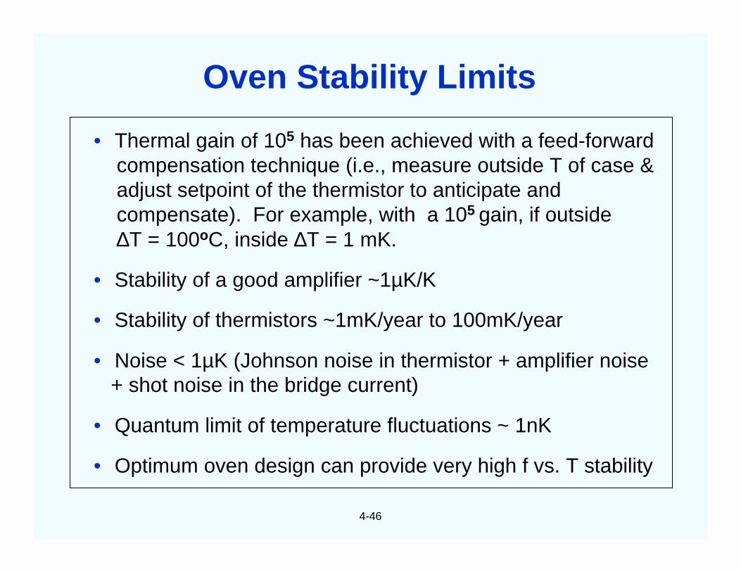
• Thermal gain of 105 has been achieved with a feed-forwardcompensation technique (i.e., measure outside T of case &adjust setpoint of the thermistor to anticipate andcompensate). For example, with a 105 gain, if outside∆T = 100oC, inside ∆T = 1 mK.
• Stability of a good amplifier ~1µK/K
• Stability of thermistors ~1mK/year to 100mK/year
• Noise < 1µK (Johnson noise in thermistor + amplifier noise+ shot noise in the bridge current)
• Quantum limit of temperature fluctuations ~ 1nK
• Optimum oven design can provide very high f vs. T stability
Oven Stability Limits
4-47
Deviation from static f vs. t = ,
where, for example, ≈≈≈≈-2 x 10⁻⁷ s/K2
for a typical AT-cut resonator
dtdT
a~
a~
Time (min)
Oven Warmup Time
Fra
ctio
nal
Fre
qu
ency
Dev
iati
on
Fro
mT
urn
ove
rF
req
uen
cy
3 6 9 12 15
10-3
10-4
10-5
-10-6
10-7
10-8
-10-8
-10-7
10-6
0
Warmup of AT- and SC-cut Resonators
4-48
Temperature (0C)
TCXO = Temperature Compensated Crystal Oscillator
Fra
ctio
nal
Fre
qu
ency
Err
or
(pp
m)
0.5
1.0
0.0
-0.5
-1.0
-25 -5 15 35 55 75
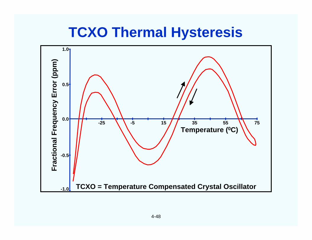
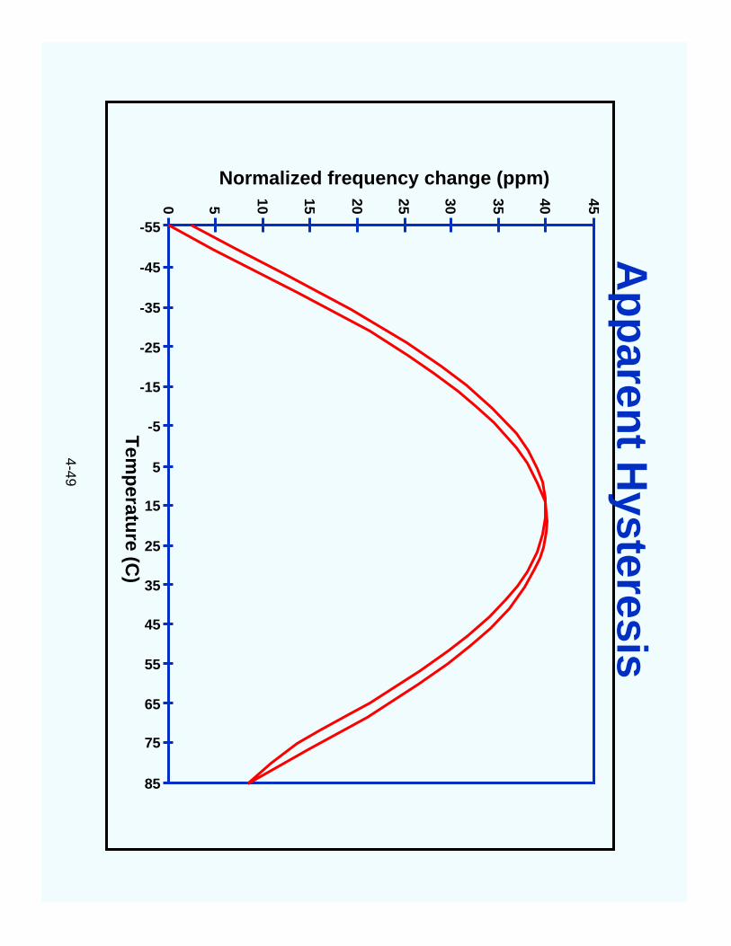
TCXO Thermal Hysteresis
4-49
Tem
peratu
re(C
)
-55
-45
-35
-25
-15
-5
5
15
25
35
45
55
65
75
85
454035302520151050
Normalized frequency change (ppm)
Ap
paren
tH
ysteresis
4-50
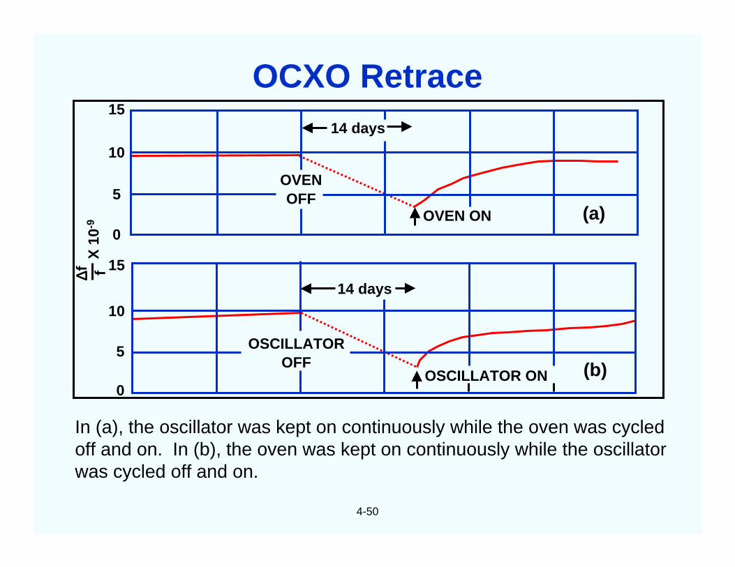
In (a), the oscillator was kept on continuously while the oven was cycledoff and on. In (b), the oven was kept on continuously while the oscillatorwas cycled off and on.
OVENOFF
(a)
14 days
14 days
OSCILLATOROFF
OSCILLATOR ON (b)
OVEN ON
∆∆ ∆∆f f15
10
5
0
15
5
0
10
X10
-9OCXO Retrace
4-51
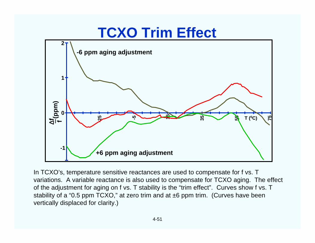
In TCXO’s, temperature sensitive reactances are used to compensate for f vs. Tvariations. A variable reactance is also used to compensate for TCXO aging. The effectof the adjustment for aging on f vs. T stability is the “trim effect”. Curves show f vs. Tstability of a “0.5 ppm TCXO,” at zero trim and at ±6 ppm trim. (Curves have beenvertically displaced for clarity.)
2
1
0
-1
∆∆ ∆∆f f(p
pm
)
-25 -5 15 35 55 75
-6 ppm aging adjustment
+6 ppm aging adjustment
T (0C)
TCXO Trim Effect
4-52
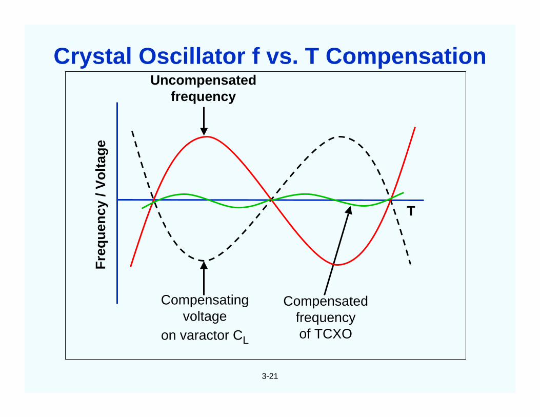
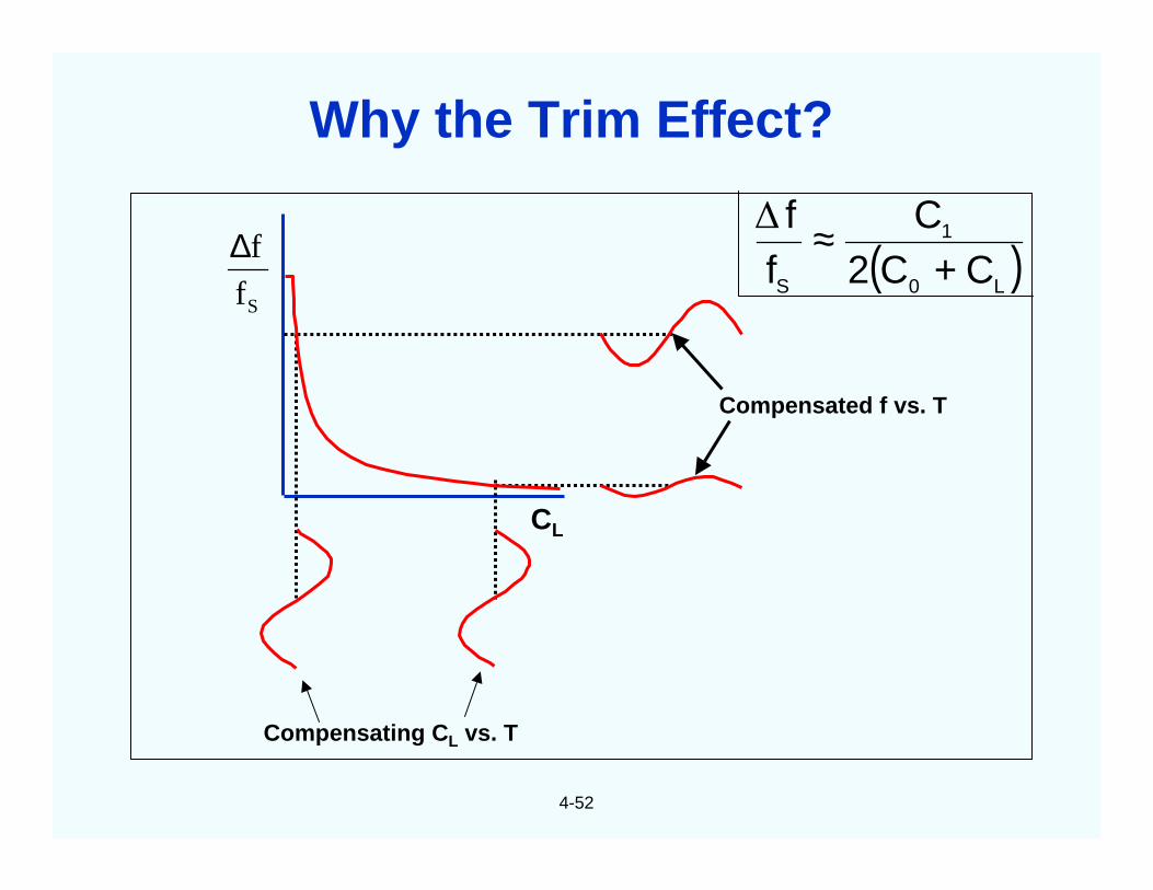
CL
Compensated f vs. T
Compensating CL vs. T
( )L0
1
S CC2C
ff
+≈∆
Sf
f∆
Why the Trim Effect?
4-53
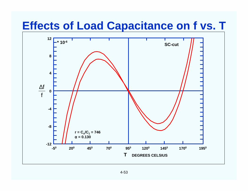
T DEGREES CELSIUS
SC-cut
r = Co/C1 = 746αααα = 0.130
ff∆
12
8
4
0
-4
-8
-12-50 200 450 700 950 1200 1450 1700 1950
* 10-6
Effects of Load Capacitance on f vs. T
4-54
(ppm)
53
M
∆T, 0C
50
40
30
20
10
0
-10
-20
-30
-50
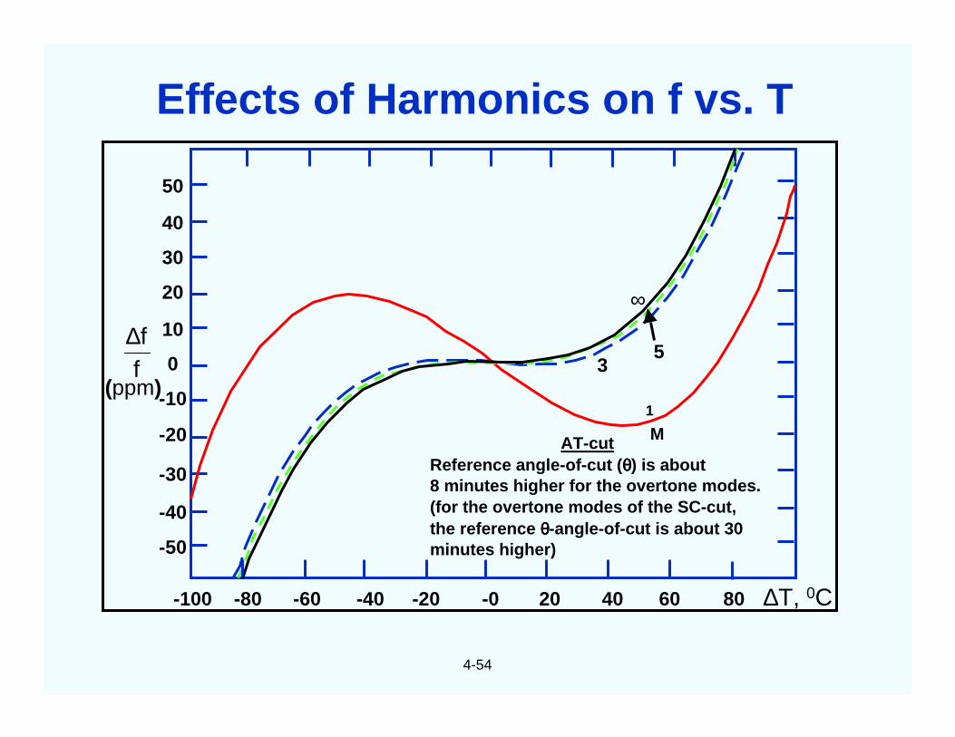
-100 -80 -40 -20 -0 20 40 60 80
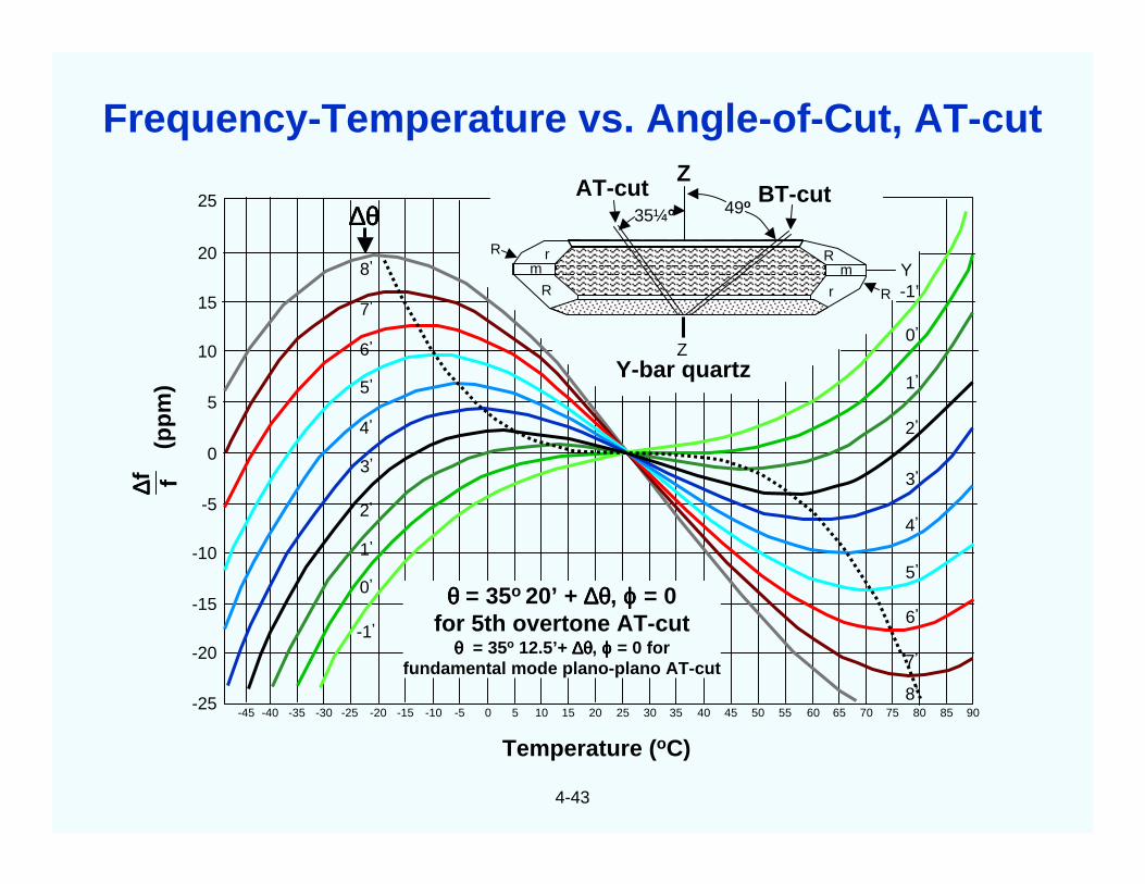
AT-cutReference angle-of-cut (θθθθ) is about8 minutes higher for the overtone modes.(for the overtone modes of the SC-cut,the reference θθθθ-angle-of-cut is about 30minutes higher)
1
-60
-40
∞
ff∆
Effects of Harmonics on f vs. T
4-55
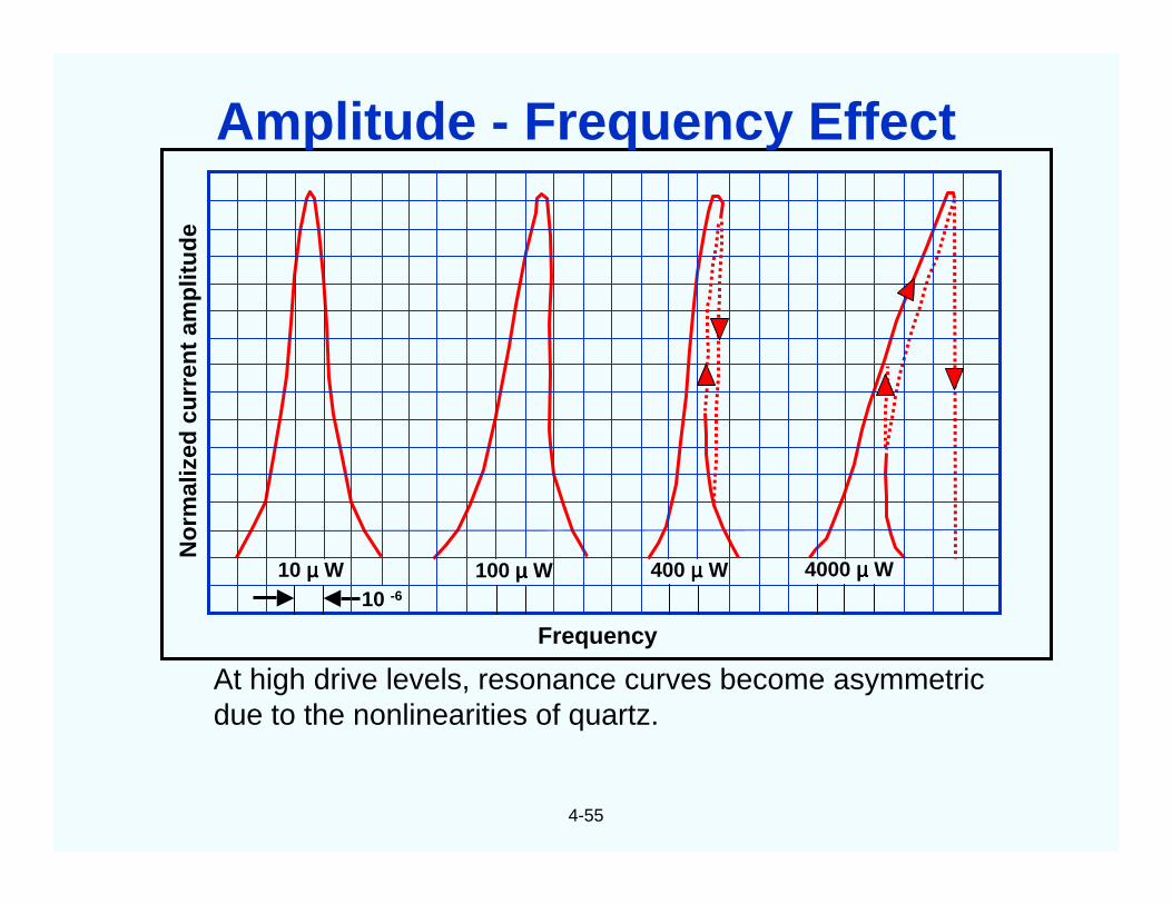
At high drive levels, resonance curves become asymmetricdue to the nonlinearities of quartz.
No
rmal
ized
curr
ent
amp
litu
de
Frequency
10 -6
10 µµµµ W 100 µµµµ W 400 µµµµ W 4000 µµµµ W
Amplitude - Frequency Effect
4-56
Fre
qu
ency
Ch
ang
e(p
arts
in10
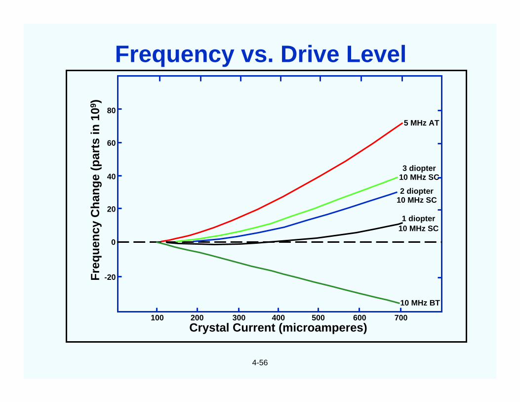
9 )80
60
40
20
0
-20
100 200 300 400 500 600 700
5 MHz AT
3 diopter10 MHz SC
2 diopter10 MHz SC
1 diopter10 MHz SC
10 MHz BT
Crystal Current (microamperes)
Frequency vs. Drive Level
4-57
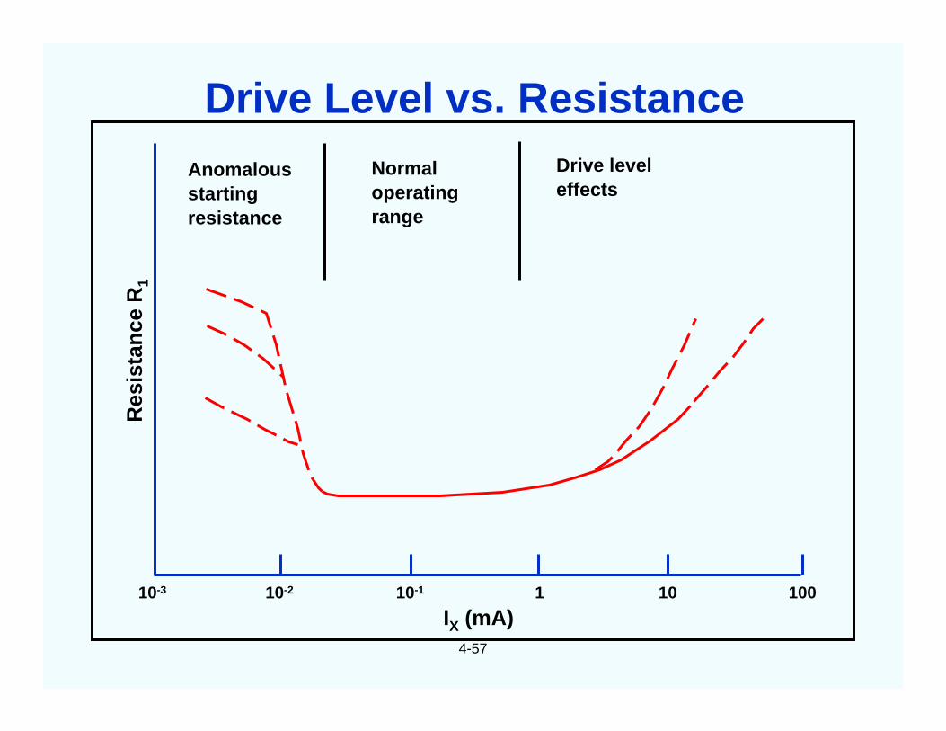
10-3 10-2 10-1 1 10 100
Res
ista
nce
R1
IX (mA)
Anomalousstartingresistance
Normaloperatingrange
Drive leveleffects
Drive Level vs. Resistance
4-58
O A
B
C
D Drive level (voltage)
Act
ivit
y(c
urr
ent)
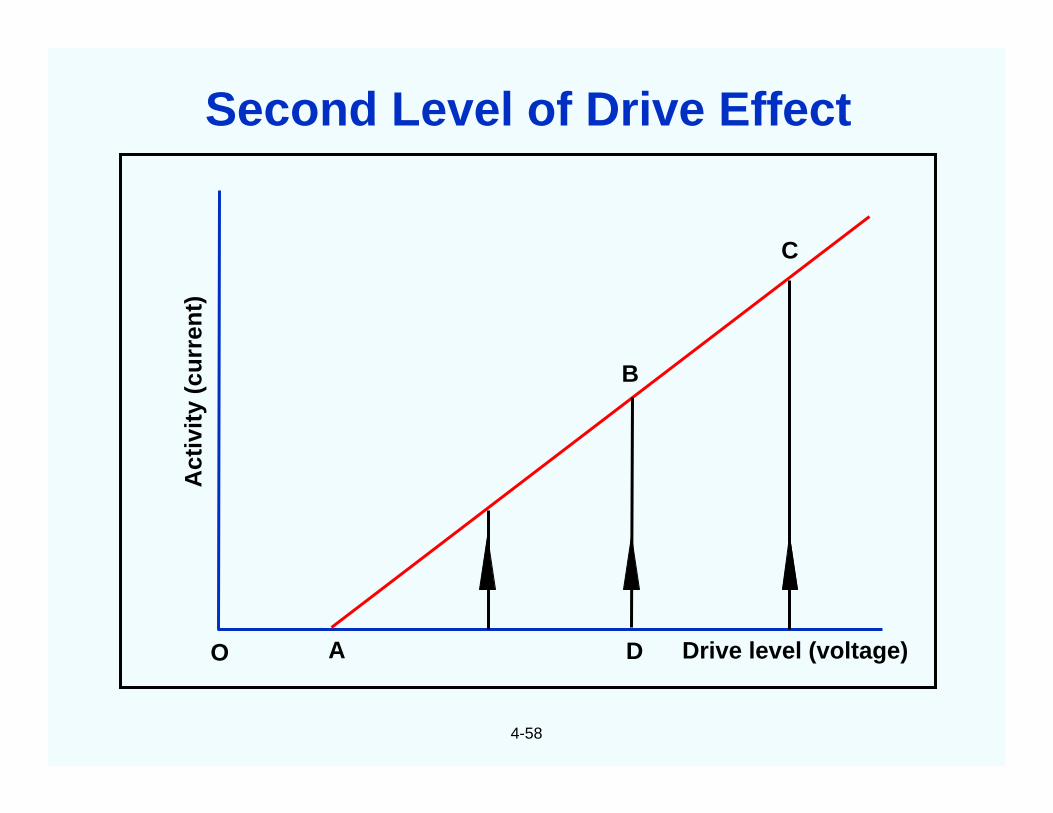
Second Level of Drive Effect
4-59
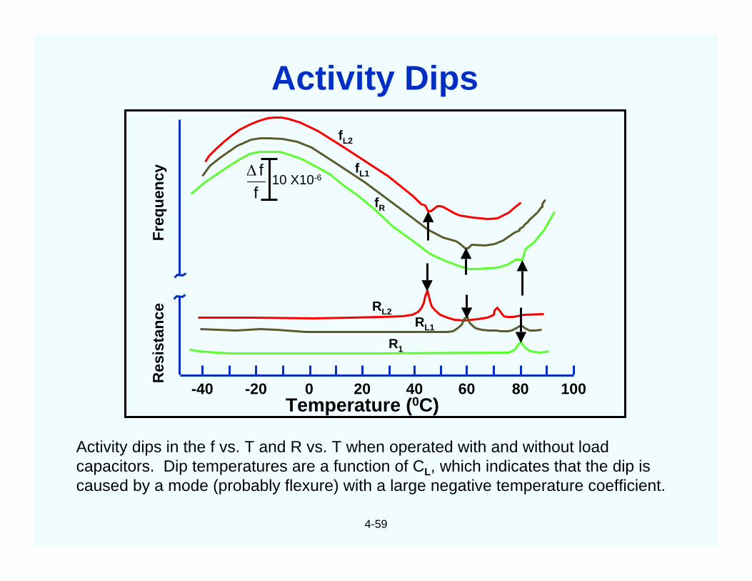
Activity dips in the f vs. T and R vs. T when operated with and without loadcapacitors. Dip temperatures are a function of CL, which indicates that the dip iscaused by a mode (probably flexure) with a large negative temperature coefficient.
Fre
qu
ency
Res
ista
nce
Temperature (0C)-40 -20 0 20 40 60 80 100
RL2RL1
R1
fL1
fL2
fR
10 X10-6
ff∆
Activity Dips
4-60
4.0
3.0
2.0
1.0
0.0
-1.00 2 4 6 8 10
No. 2
No. 3
No. 4
Fre
qu
ency
dev
iati
on
(pp
b)
Elapsed time (hours)
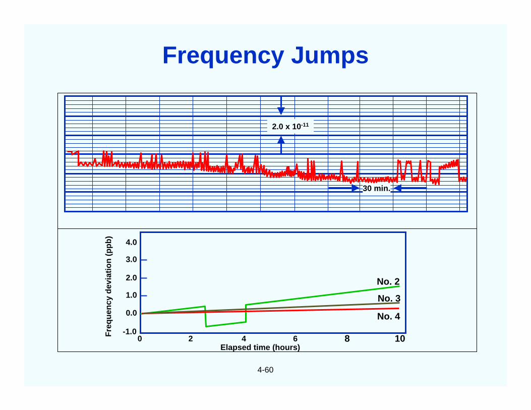
2.0 x 10⁻¹¹
30 min.
Frequency Jumps
4-61
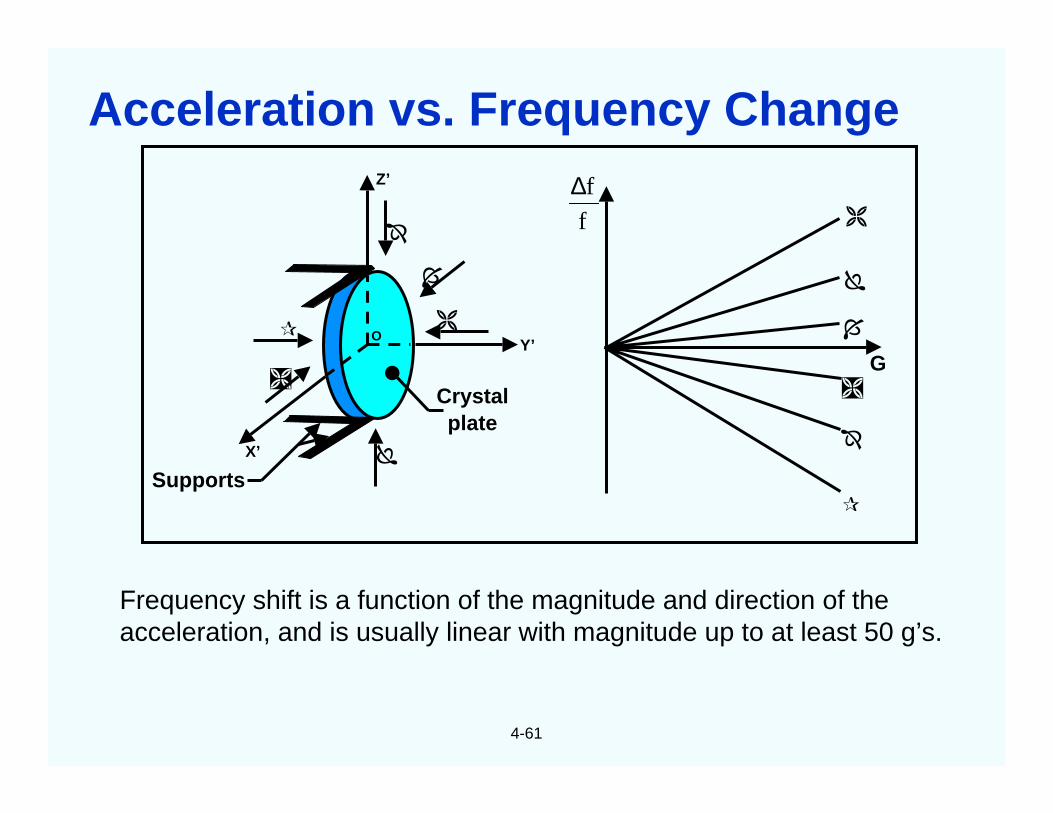
Frequency shift is a function of the magnitude and direction of theacceleration, and is usually linear with magnitude up to at least 50 g’s.
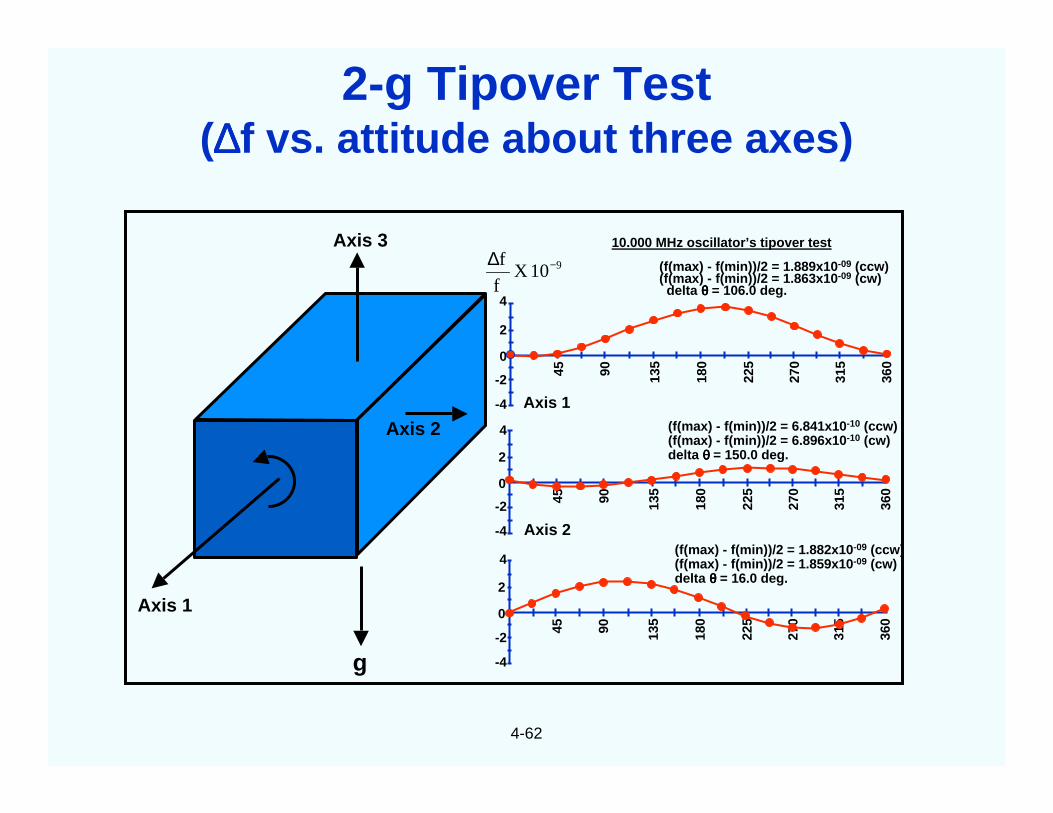
2-g Tipover Test(∆∆∆∆f vs. attitude about three axes)
4-63
Tim
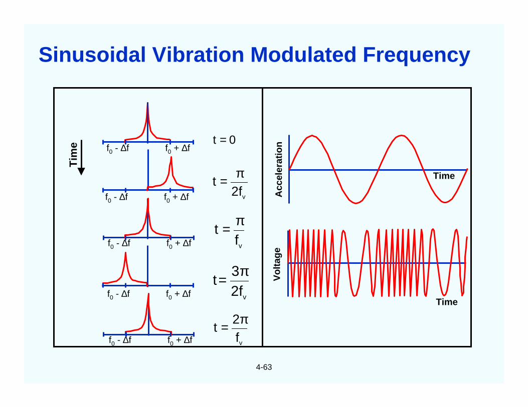
e f0 - ∆f f0 + ∆f
f0 - ∆f f0 + ∆f
f0 - ∆f f0 + ∆f
f0 - ∆f f0 + ∆f
f0 - ∆f f0 + ∆f
Acc
eler
atio
n
Time
Time
Vo
ltag
e
0t =
v2ft
π=
vft
π=
v2f3
tπ=
vf2
tπ=
Sinusoidal Vibration Modulated Frequency
4-64
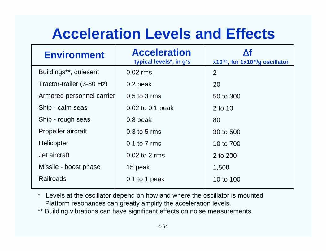
Environment
Buildings**, quiesent
Tractor-trailer (3-80 Hz)
Armored personnel carrier
Ship - calm seas
Ship - rough seas
Propeller aircraft
Helicopter
Jet aircraft
Missile - boost phase
Railroads
Accelerationtypical levels*, in g’s
0.02 rms
0.2 peak
0.5 to 3 rms
0.02 to 0.1 peak
0.8 peak
0.3 to 5 rms
0.1 to 7 rms
0.02 to 2 rms
15 peak
0.1 to 1 peak
∆∆∆∆fx10-11, for 1x10⁻⁹/g oscillator
2
20
50 to 300
2 to 10
80
30 to 500
10 to 700
2 to 200
1,500
10 to 100
* Levels at the oscillator depend on how and where the oscillator is mountedPlatform resonances can greatly amplify the acceleration levels.
** Building vibrations can have significant effects on noise measurements
Acceleration Levels and Effects
4-65
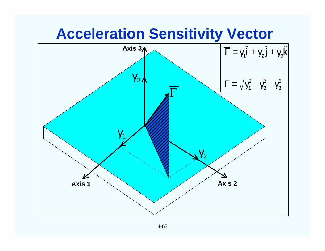
Axis 1 Axis 2
Axis 3
γ1
γ2
γ3
Γ23
22
21
321 kji
γγγ=Γ
γ+γ+γ=Γ
++
Acceleration Sensitivity Vector
4-66
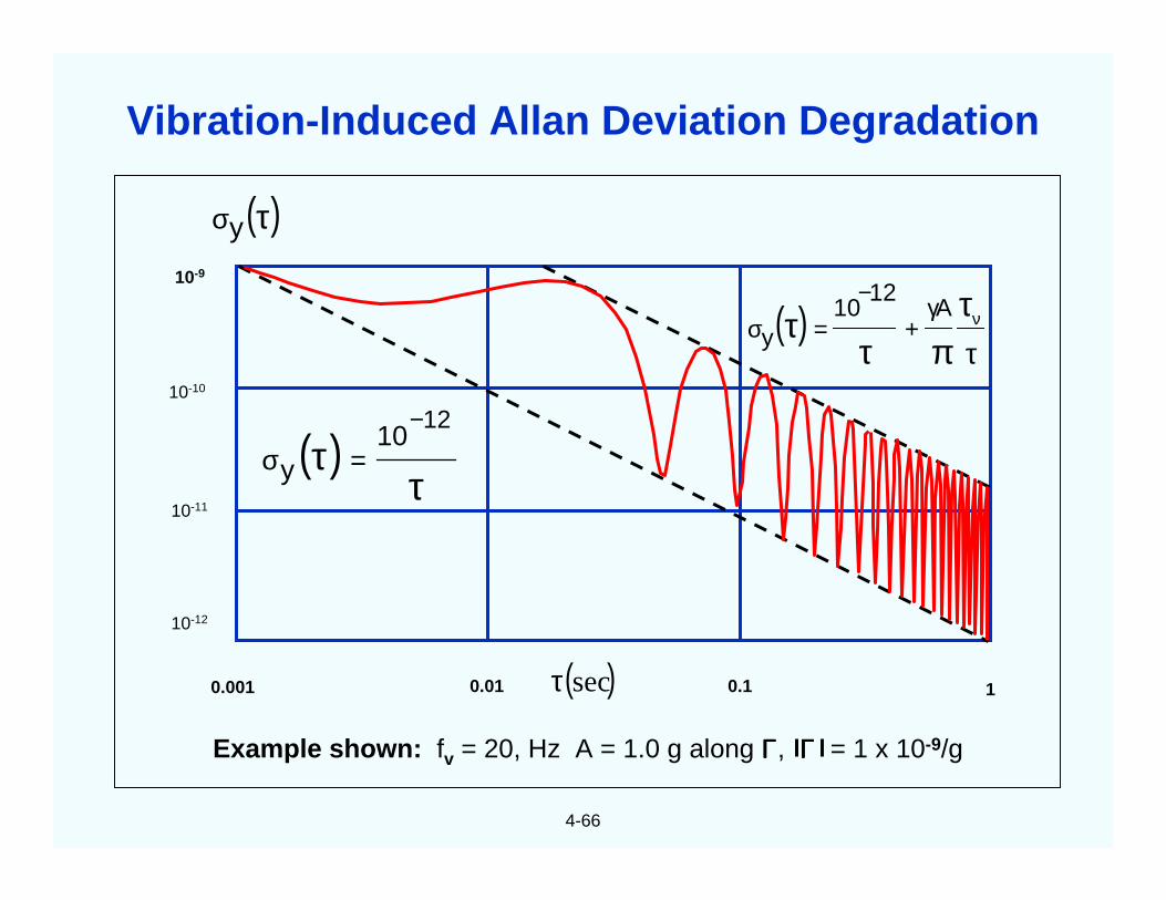
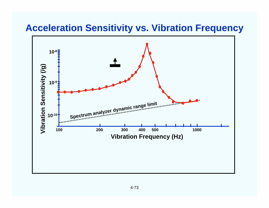
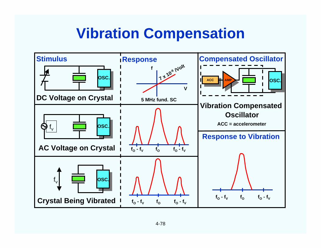
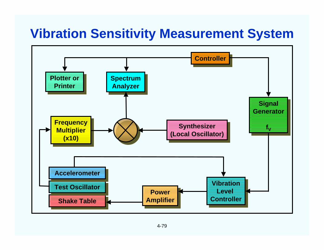
Example shown: fv = 20, Hz A = 1.0 g along ΓΓΓΓ, ΓΓΓΓ = 1 x 10⁻⁹/g
0.001 0.01 0.1 1
10-9
10-10
10-11
10-12
( )secτ
( )τντ
πττ γ
+−
=σA
1210
y
( )τ
τ−
=σ12
10y
( )τσy
Vibration-Induced Allan Deviation Degradation
4-67
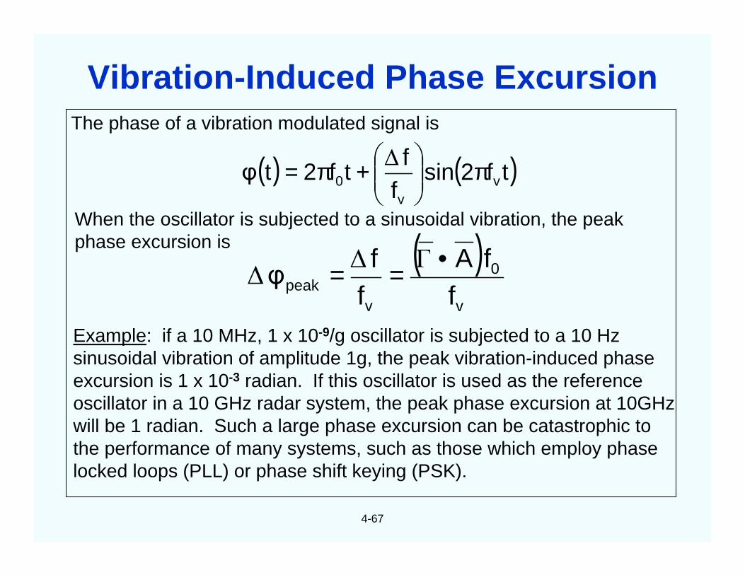
The phase of a vibration modulated signal is
When the oscillator is subjected to a sinusoidal vibration, the peakphase excursion is
Example: if a 10 MHz, 1 x 10⁻⁹/g oscillator is subjected to a 10 Hzsinusoidal vibration of amplitude 1g, the peak vibration-induced phaseexcursion is 1 x 10⁻³ radian. If this oscillator is used as the referenceoscillator in a 10 GHz radar system, the peak phase excursion at 10GHzwill be 1 radian. Such a large phase excursion can be catastrophic tothe performance of many systems, such as those which employ phaselocked loops (PLL) or phase shift keying (PSK).
( ) ( )tf2sinff
tf2tφ vv
0 π
+π= ∆
( )v
0
vpeak f
fAff
φ•== Γ∆
∆
Vibration-Induced Phase Excursion
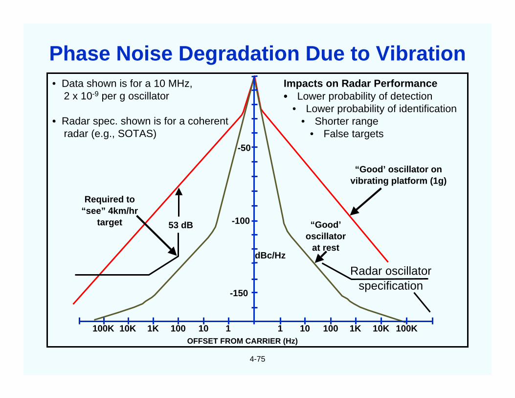
4-68
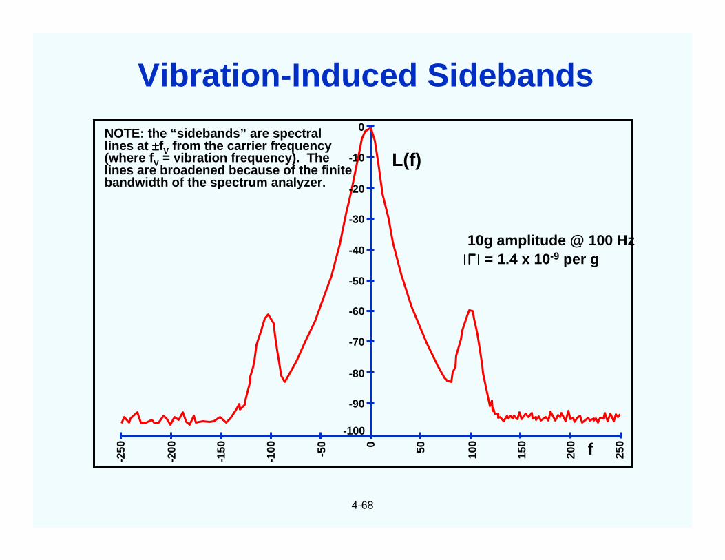
L(f)
10g amplitude @ 100 HzΓΓΓΓ = 1.4 x 10⁻⁹ per g
0
-10
-20
-30
-40
-50
-60
-70
-80
-90
-100
-250
-200
-150
-100 -50 0 50 100
150
200
250f
NOTE: the “sidebands” are spectrallines at ±±±±fV from the carrier frequency(where fV = vibration frequency). Thelines are broadened because of the finitebandwidth of the spectrum analyzer.
Vibration-Induced Sidebands
4-69
0
-10
-20
-30
-40
-50
-60
-70
-80
-90
-100
-250
-200
-150
-100 -50 0 50 100
150
200
250f
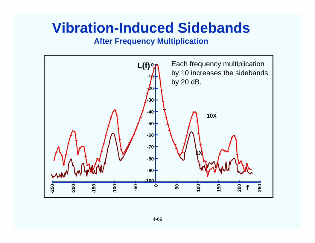
L(f) Each frequency multiplicationby 10 increases the sidebandsby 20 dB.
10X
1X
Vibration-Induced SidebandsAfter Frequency Multiplication
4-70
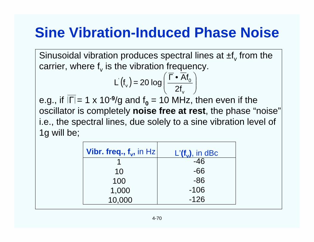
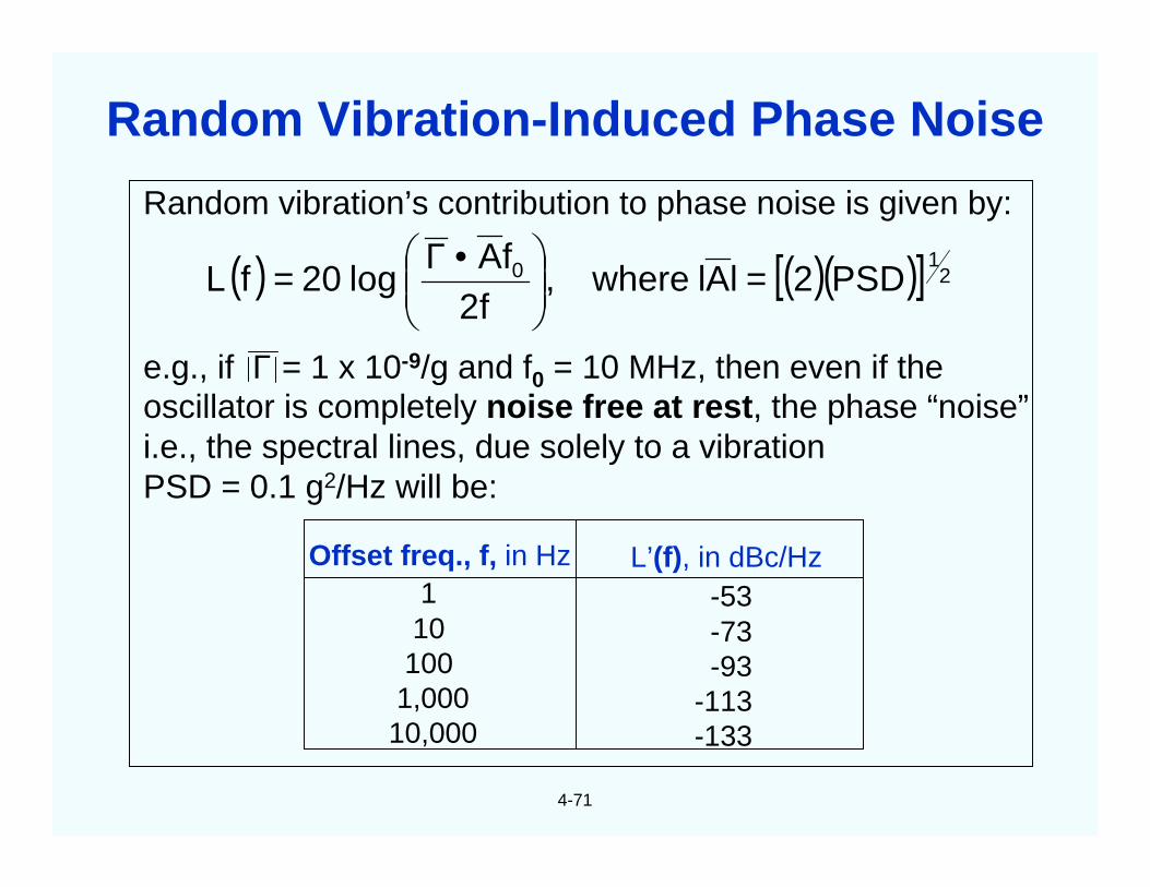
Sinusoidal vibration produces spectral lines at ±fv from thecarrier, where fv is the vibration frequency.
e.g., if Γ = 1 x 10⁻⁹/g and f0 = 10 MHz, then even if theoscillator is completely noise free at rest, the phase “noise”i.e., the spectral lines, due solely to a sine vibration level of1g will be;
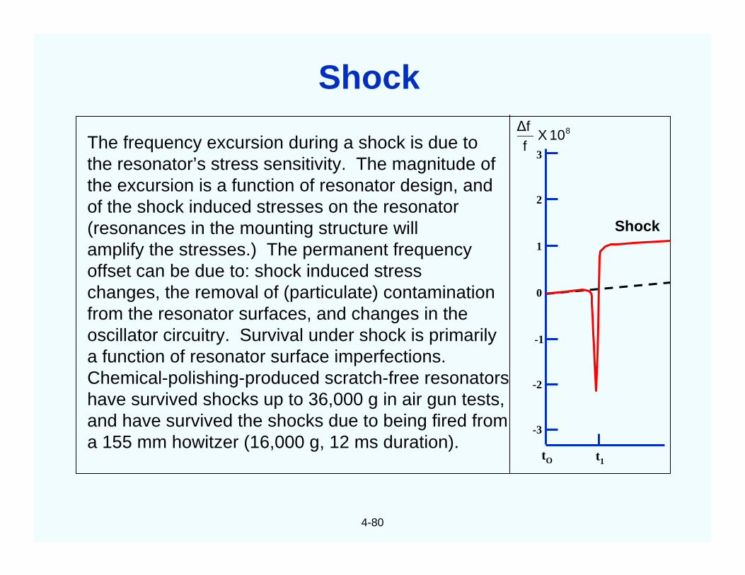
Vibr. freq., fv, in Hz1101001,00010,000
-46-66-86
-106-126
L’(fv), in dBc
( )
•Γ=v
0v f2
fAlog20f'L
Sine Vibration-Induced Phase Noise
4-71
Random vibration’s contribution to phase noise is given by:
e.g., if Γ = 1 x 10⁻⁹/g and f0 = 10 MHz, then even if theoscillator is completely noise free at rest, the phase “noise”i.e., the spectral lines, due solely to a vibrationPSD = 0.1 g2/Hz will be:
Offset freq., f, in Hz1101001,00010,000
L’(f), in dBc/Hz-53-73-93
-113-133
( ) ( )( )[ ] 210 PSD2lAlwhere,
f2fA
log20f =
•Γ=L
Random Vibration-Induced Phase Noise
4-72
-70
-80
-90
-100
-110
-120
-130
-140
-150
-160
L(f
)(d
Bc)
1K 2K3005
45 dBL(f) without vibration
L(f) under the randomvibration shown
5 300 1K 2K
PS
D(g
2 /H
z)
.04
.07
Frequency (Hz)
Typical aircraftrandom vibration
envelope
Phase noise under vibration is for ΓΓΓΓ = 1 x 10⁻⁹ per g and f = 10 MHz
Random-Vibration-Induced Phase Noise
4-73
Spectrum analyzer dynamic range limit
Vib
rati
on
Sen
siti
vity
(/g
)10-8
10-9
10-10
100 200 300 400 500 1000
Vibration Frequency (Hz)
Acceleration Sensitivity vs. Vibration Frequency
4-74
Resonator acceleration sensitivities range from the low parts in 1010 per g forthe best commercially available SC-cuts, to parts in 107 per g for tuning-fork-typewatch crystals. When a wide range of resonators were examined: AT, BT, FC, IT,SC, AK, and GT-cuts; 5 MHz 5th overtones to 500 MHz fundamental mode invertedmesa resonators; resonators made of natural quartz, cultured quartz, and sweptcultured quartz; numerous geometries and mounting configurations (includingrectangular AT-cuts); nearly all of the results were within a factor of three of 1x10⁻⁹
per g. On the other hand, the fact that a few resonators have been found to havesensitivities of less than 1x10⁻¹⁰ per g indicates that the observed accelerationsensitivities are not due to any inherent natural limitations.
Theoretical and experimental evidence indicates that the major variables yetto be controlled properly are the mode shape and location (i.e., the amplitude ofvibration distribution), and the strain distribution associated with the mode ofvibration. Theoretically, when the mounting is completely symmetrical with respectto the mode shape, the acceleration sensitivity can be zero, but tiny changes fromthis ideal condition can cause a significant sensitivity. Until the accelerationsensitivity problem is solved, acceleration compensation and vibration isolation canprovide lower than 1x10⁻¹⁰ per g, for a limited range of vibration frequencies, and ata cost.
Acceleration Sensitivity of Quartz Resonators
4-75
OFFSET FROM CARRIER (Hz)
Required to“see” 4km/hr
target “Good’oscillator
at rest
“Good’ oscillator onvibrating platform (1g)
Radar oscillatorspecification
-50
-100
-150
53 dB
dBc/Hz
100K 10K 1K 100 10 1 1 10 100 1K 10K 100K
Impacts on Radar Performance•••• Lower probability of detection
• Lower probability of identification• Shorter range
• False targets
• Data shown is for a 10 MHz,2 x 10-9 per g oscillator
•• Radar spec. shown is for a coherentradar (e.g., SOTAS)
Phase Noise Degradation Due to Vibration
4-76
To “see” 4 km/h targets, low phase noise 70 Hz from thecarrier is required. Shown is the probability of detection of4 km/h targets vs. the phase noise 70 Hz from the carrierof a 10 MHz reference oscillator. (After multiplication to 10GHz the phase noise will be at least 60 dB higher.) Thephase noise due to platform vibration, e.g., on an aircraft,reduces the probability of detection of slow-moving targetsto zero.
100
80
60
40
20
-140 -135 -130 -125 -120 -115 -110
High NoiseLow Noise
Phase Noise (dBc/Hz)at 70 Hz from carrier, for 4 km/h targets
Pro
bab
ility
of
Det
ecti
on
(%)
Coherent Radar Probability of Detection
4-77
Limitations
• Poor at low frequencies
• Adds size, weight and cost
• Ineffective for acousticnoise
Region ofAmplification
1
0.2 1 2Forcing Freq./Resonant Freq.
Tra
nsm
issi
bilit
y
Region ofIsolation
Vibration Isolation
4-78
Stimulus
OSC.
DC Voltage on Crystal
OSC.fv
AC Voltage on Crystal
OSC.fv
Crystal Being Vibrated
Responsef
7 x 10⁻⁹ /Volt
V
5 MHz fund. SC
fO - fV fO - fVfO
fO - fV fO - fVfO
ACCACC OSC.
Compensated Oscillator
AMP
Vibration CompensatedOscillator
ACC = accelerometer
Response to Vibration
fO - fV fO - fVfO
Vibration Compensation
4-79
ControllerController
SignalGenerator
fV
SignalGenerator
fV
SpectrumAnalyzer
SpectrumAnalyzer
Plotter orPrinter
Plotter orPrinter
VibrationLevel
Controller
VibrationLevel
ControllerPower
Amplifier
PowerAmplifierShake TableShake Table
Test OscillatorTest Oscillator
AccelerometerAccelerometer
FrequencyMultiplier
(x10)
FrequencyMultiplier
(x10)Synthesizer
(Local Oscillator)
Synthesizer(Local Oscillator)
Vibration Sensitivity Measurement System
4-80
The frequency excursion during a shock is due tothe resonator’s stress sensitivity. The magnitude ofthe excursion is a function of resonator design, andof the shock induced stresses on the resonator(resonances in the mounting structure willamplify the stresses.) The permanent frequencyoffset can be due to: shock induced stresschanges, the removal of (particulate) contaminationfrom the resonator surfaces, and changes in theoscillator circuitry. Survival under shock is primarilya function of resonator surface imperfections.Chemical-polishing-produced scratch-free resonatorshave survived shocks up to 36,000 g in air gun tests,and have survived the shocks due to being fired froma 155 mm howitzer (16,000 g, 12 ms duration).
Shock
3
2
1
0
-1
-2
-3
tO t1
810Xf∆f
Shock
4-81
Idealized frequency vs. time behavior for a quartz resonator following a pulseof ionizing radiation.
t0 tTime
Fre
qu
ency
fO
ft
fSS
∆∆∆∆fSS
fO = original, preirradiationfrequency
fSS = steady-state frequency(0.2 to 24 hours after
exposure)
∆∆∆∆fSS = steady-state frequencyoffset
fT = frequency at time t
10-11 for natural quartz (and R increase can stop the oscillation)∆∆∆∆fSS/rad* = 10-12 for cultured quartz
10-13 for swept cultured quartz
* for a 1 megarad dose (the coefficients are dose dependent)
Radiation-Induced Frequency Shifts
4-82
Fra
ctio
nalF
requ
ency
,ppb
10
0
-10
-20
-30
-4010 102 103 104 105 106
Dose, rad(SiO2)
1. Initial irradiation
2. Reirradiation (after 2.5 x 10⁴ rad)
3. Reirradiation (after >106 rad)
Five irradiations; responses during the 4th and 5thirradiations repeated the results of the 3rd. Atleast 2 days elapsed between successiveirradiations.
Initial slopes:1st: -1 x 10⁻⁹/rad2nd: +1 x 10-11/rad3rd: +3 x 10-12/rad4th: +3 x 10-12/rad5th: +5 x 10-12/rad
• For a 4 MHz AT-cut resonator, X-ray dose of 6 x 10⁶ rads produced ∆f = 41 Hz.• Activiation energies were calculated from the temperature dependence of the
annealing curves. The experimental results can be reproduced by twoprocesses, with activation energies E1 = 0.3 ± 0.1 eV and E2 = 1.3 ± 0.3eV.
• Annealing was complete in less than 3 hours at > 2400C.
xxx x
x
x
xx
x
x
x
x
-∆f
40
20
0
Fre
quen
cych
ange
,Hz
100 200 300x
∆fS = 41 Hz
X T= 4330K (1600C)X T= 4540K
X T= 4680K
X T= 4880K (2150C)
Annealing time, minutes
T = 5130K(2400C)
Annealing of Radiation Induced f Changes
4-85
4
0
-4
-8
-12
-16
-20
-24
∆∆ ∆∆f/f
(pp
108 )
Time(seconds after event)
0.1 1.0 10 100 1000
X X
X
XX
XX
XXX X
X
X
XX
XXXX
X
X
XX
X
X
X
X
X
Experimental data, dose = 1.3 x 10⁴ rads, SC-cut
Experimental data, dose = 2.3 x 10⁴ rads, AT-cut
Model Calculation: AT-cut
X
Transient ∆∆∆∆f After a Pulse of γγγγ Radiation
4-86
The curves show the series resonance resistance, RS, vs. time following a4 x 104 rad pulse. Resonators made of swept quartz show no change in RSfrom the earliest measurement time (1 ms) after exposure, at roomtemperature. Large increases in RS (i.e., large decrease in the Q) will stop theoscillation.
RS
inO
hm
s
14
13
12
11
10
9
8
7
6
5
80
70
60
50
40
30
0.001 0.01 0.1 1.0 10 100 1000
Val
ue
of
Q-1
x10
6
Time following exposure (seconds)
32 MHz AT-cut resonators
Preirradiation value RS
(S-26)(S-25)
C-22
C-7
N-4
N-4 (Natural) 4.5 x 10⁴ RC-7 (Unswept synthetic) 4 x 10⁴ RC-22 (Unswept synthetic) 3.5 x 10⁴ RS-25 Swept synthetic) 4 x 10⁴ RS-26 Swept synthetic) 4 x 10⁴ R
Effects of Flash X-rays on RS
4-87
Fast Neutron Exposure (nvt) x1017
0 1 2 3 4 5 6 7 8 9 10 11 12
1000
900
800
700
600
500
400
300
200
100
0
Fre
qu
ency
Dev
iati
on
,X
106
∆∆ ∆∆f f
5 MHzAT-cut
Slope = 0.7 x 10⁻²¹/n/cm2
Frequency Change due to Neutrons
4-88
A fast neutron can displace about 50 to 100 atoms before it comesto rest. Most of the damage is done by the recoiling atoms. Net resultis that each neutron can cause numerous vacancies and interstitials.
(1) (2) (3) (4)
Neutron Damage
4-89
Dose vs. frequency change is nonlinear; frequency change per rad is larger at low doses.
At doses > 1 kRad, frequency change is quartz-impurity dependent. The ionizing radiationproduces electron-hole pairs; the holes are trapped by the impurity Al sites while thecompensating cation (e.g., Li+ or Na+) is released. The freed cations are loosely trapped alongthe optic axis. The lattice near the Al is altered, the elastic constant is changed; therefore, thefrequency shifts. Ge impurity is also troublesome.
At a 1 MRad dose, frequency change ranges from pp 1011 per rad for natural quartz to pp 1014
per rad for high quality swept quartz.
Frequency change is negative for natural quartz; it can be positive or negative for cultured andswept cultured quartz.
Frequency change saturates at doses >> 106 rads.
Q degrades upon irradiation if the quartz contains a high concentration of alkali impurities; Q ofresonators made of properly swept cultured quartz is unaffected.
High dose radiation can also rotate the f vs. T characteristic.
Frequency change anneals at T > 240°C in less than 3 hours.
Preconditioning (e.g., with doses > 105 rads) reduces the high dose radiation sensitivities uponsubsequent irradiations.
At < 100 rad, frequency change is not well understood. Radiation induced stress relief & surfaceeffects (adsorption, desorption, dissociation, polymerization and charging) may be factors.
Summary - Steady-State Radiation Results
4-90
For applications requiring circuits hardened to pulse irradiation, quartz resonators are theleast tolerant element in properly designed oscillator circuits.
Resonators made of unswept quartz or natural quartz can experience a large increase in Rsfollowing a pulse of radiation. The radiation pulse can stop the oscillation.
Natural, cultured, and swept cultured AT-cut quartz resonators experience an initialnegative frequency shift immediately after exposure to a pulse of X-rays (e.g., 104 to105 Rad of flash X-rays), ∆f/f is as large as -3ppm at 0.02sec after burst of 1012 Rad/sec.
Transient f offset anneals as t-1/2; the nonthermal-transient part of the f offset is probablydue to the diffusion and retrapping of hydrogen at the Al3+ trap.
Resonators made of properly swept quartz experience a negligibly small change in Rswhen subjected to pulsed ionizing radiation (therefore, the oscillator circuit does not requirea large reserve of gain margin).
SC-cut quartz resonators made of properly swept high Q quartz do not exhibit transientfrequency offsets following a pulse of ionizing radiation.
Crystal oscillators will stop oscillating during an intense pulse of ionizing radiation becauseof the large prompt photoconductivity in quartz and in the transistors comprising theoscillator circuit. Oscillation will start up within 15µsec after a burst if swept quartz is usedin the resonator and the oscillator circuit is properly designed for the radiation environment.
Summary - Pulse Irradiation Results
4-91
When a fast neutron (~MeV energy) hurtles into a crystal lattice and collides with anatom, it is scattered like a billiard ball. The recoiling atom, having an energy (~104
to 106 eV) that is much greater than its binding energy in the lattice, leaves behinda vacancy and, as it travels through the lattice, it displaces and ionizes other atoms.A single fast neutron can thereby produce numerous vacancies, interstitials, andbroken interatomic bonds. Neutron damage thus changes both the elasticconstants and the density of quartz. Of the fast neutrons that impinge on aresonator, most pass through without any collisions, i.e., without any effects on theresonator. The small fraction of neutrons that collide with atoms in the lattice causethe damage.
Frequency increases approximately linearly with fluence. For AT- and SC-cutresonators, the slopes range from +0.7 x 10⁻²¹/n/cm2, at very high fluences (1017 to1018n/cm2) to 5 x 10-21/n/cm2 at 1012 to 1013n/cm2, and 8 x 10-21/n/cm2at 1010 to1012n/cm2. Sensitivity probably depends somewhat on the quartz defect densityand on the neutron energy distribution. (Thermonuclear neutrons cause moredamage than reactor neutrons.)
Neutron irradiation also rotates the frequency vs. temperature characteristic.
When a heavily neutron irradiated sample was baked at 500°C for six days, 90% ofthe neutron-induced frequency shift was removed (but the 10% remaining was still93 ppm).
Summary - Neutron Irradiation Results
4-92
Electric field - affects doubly-rotated resonators; e.g., a voltage on the electrodes of a 5 MHzfundamental mode SC-cut resonator results in a ∆f/f = 7 x 10⁻⁹ per volt. The voltage can alsocause sweeping, which can affect the frequency (of all cuts), even at normal operatingtemperatures.
Magnetic field - quartz is diamagnetic, however, magnetic fields can induce Eddy currents, andwill affect magnetic materials in the resonator package and the oscillator circuitry. Induced acvoltages can affect varactors, AGC circuits and power supplies. Typical frequency change of a"good" quartz oscillator is <<10-10 per gauss.
Ambient pressure (altitude) - deformation of resonator and oscillator packages, and change inheat transfer conditions affect the frequency.
Humidity - can affect the oscillator circuitry, and the oscillator's thermal properties, e.g.,moisture absorbed by organics can affect dielectric constants.
Power supply voltage, and load impedance - affect the oscillator circuitry, and indirectly, theresonator's drive level and load reactance. A change in load impedance changes the amplitudeor phase of the signal reflected into the oscillator loop, which changes the phase (andfrequency) of the oscillation. The effects can be minimized by using a (low noise) voltageregulator and buffer amplifier.
Gas permeation - stability can be affected by excessive levels of atmospheric hydrogen andhelium diffusing into "hermetically sealed" metal and glass enclosures (e.g., hydrogen diffusionthrough nickel resonator enclosures, and helium diffusion through glass Rb standard bulbs).
Other Effects on Stability
4-93
In attempting to measure the effect of a single influence, one often encountersinterfering influences, the presence of which may or may not be obvious.
Measurement
Resonator aging
Short term stability
Vibration sensitivity
2-g tipover sensitivity
Resonator f vs. T(static)
Radiation sensitivity
Interfering Influence
∆T due to oven T (i.e., thermistor) aging∆ drive level due to osc. circuit aging
Vibration
Induced voltages due to magnetic fields
∆T due to convection inside oven
Thermal transient effect, humidityT-coefficient of load reactances
∆T, thermal transient effect, aging
Interactions Among Influences
5
CHAPTER 5Quartz Material Properties
5-1
• The autoclave is filled to somepredetermined factor with water plusmineralizer (NaOH or Na2CO3).
• The baffle localizes the temperature gradientso that each zone is nearly isothermal.
• The seeds are thin slices of (usually)Z-cut single crystals.
• The nutrient consists of small (~2½ to 4 cm)pieces of single-crystal quartz (“lascas”).
• The temperatures and pressures aretypically about 3500C and 800 to 2,000atmospheres; T2 - T1 is typically 40C to 100C.
• The nutrient dissolves slowly (30 to 260 daysper run), diffuses to the growth zone, anddeposits onto the seeds.
Cover
Closurearea
Autoclave
Seeds
Baffle
Solute-nutrient
Nutrientdissolving
zone, T2
T2 > T1
Growthzone, T1
Nutrient
Hydrothermal Growth of Quartz
Anisotropic Etching
5-2
Y
+X
Z
+X
Looking along Y-axis Looking along Z-axis
Deeply Dissolved Quartz Sphere
5-3
Etchant Must:1. Diffuse to Surface2. Be Adsorbed3. React Chemically
Reaction Products Must:4. Be Desorbed5. Diffuse Away
Diffusion Controlled Etching:
Lapped surface
Chemically polished surface
Etching & Chemical Polishing
5-4
Y
X
r z zr
Y
X
rr zz
mm m
m
rrz z
Y
Z
Left-Handed Right-Handed
Y
Z
S
X
S
X
Left-Handed and Right-Handed Quartz
5-5
Si Si
Si Si
O
O
O
O
Si
109o
Z
Y
144.2o
The Quartz Lattice
5-6
Quartz Property
Q
Purity (Al, Fe, Li, Na, K,-OH, H2O)
Crystalline Perfection,Strains
Inclusions
Device and Device-Fabrication Property
Oscillator short-term stability, phase noiseclose to carrier, long-term stability, filter loss
Radiation hardness, susceptibility to twinning,optical characteristics
High-temperature processing and applications,resonator Q, optical characteristics, etchability
Quartz Properties’ Effects on Device Properties
5-7
= Oxygen
= Si4+
Al
H
Axis of channel
Al
H
Al
Li
0.089 eV
Al
Na
0.143 eV
0.055 eV
Al
K
0.2 eV
A)
E)D)C)
B)a
Ions in Quartz - Simplified Model
Ox
OxOx
OxOx
Ox
Ox
Ox
H+
M+ Al3+
Al3+
Al3+
Ox
OxOx
Al-OH center
OH molecule
Al-M+ center
InterstitialAlkali
5-8
Hole trapped in nonbondingoxygen p orbital
h+
Al-hole center
Aluminum Associated Defects
High voltage powersupply
Thermometer
AmmeterZ Cr-Au
OvenT = 500OC
E = 1000 V/cm
5-9
I
Time
0.5 µµµµa/cm2
Quartz bar
Sweeping
5-10
• Infrared absorption coefficient*
• Etch-channel density *
• Etch-pit density
• Inclusion density *
• Acoustic attenuation
• Impurity analysis
• X-ray topography
• UV absorption
• Birefringence along the optic axis
• Thermal shock induced fracture
• Electron spin resonance
• ? ? ?
* EIA Standard 477-1 contains standard test method for this quantity
Quartz Quality Indicators
5-11
Tra
nsm
issi
on
(%)
Wave number (cm-1)
20
40
60
80
100
0
2.5 3.0 3.5 4.0
3500
3585
33003200
3410
4000 3500 3000 2500
E parallel to Z
E parallel to X
Infrared Absorption of Quartz
5-12
One of the factors that determine the maximum achievable resonator Q is theOH content of the quartz. Infrared absorption measurements are routinely usedto measure the intensities of the temperature-broadened OH defect bands.The infrared absorption coefficient αααα is defined by EIA Standard 477-1 as
Y-cut thickness in cmα =A (3500 cm-1) - A (3800 cm-1)
where the A’s are the logarithm (base 10) of the fraction of the incident beamabsorbed at the wave numbers in the parentheses.
* In millions, at 5 MHz (α is a quality indicator for unswept quartz only).
GradeABCDE
αααα, in cm-1
0.030.0450.060
0.120.25
Approx. max. Q*3.02.21.81.00.5
Infrared Absorption Coefficient
Electrical twinning Optical Twinning
• The X-axes of quartz, the electrical axes, are parallel to the line bisectingadjacent prism faces; the +X-direction is positive upon extension due totension.
• Electric twinning (also called Dauphiné twinning) consists of localized reversalof the X-axes. It usually consists of irregular patches, with irregularboundaries. It can be produced artificially by inversion from high quartz,thermal shock, high local pressure (even at room temperature), and by anintense electric field.
• In right-handed quartz, the plane of polarization is rotated clockwise as seenby looking toward the light source; in left handed, it is counterclockwise.Optically twinned (also called Brazil twinned) quartz contains both left andright-handed quartz. Boundaries between optical twins are usually straight.
The diagrams illustrate the relationship between the axial systemand hand of twinned crystals. The arrows indicate the hand.
Electrical(Dauphine)
Combined
Optical(Brazil)
+
+
+
+
+
+
+
+
+
+
+
++
+
++
+
+-
-
-
-
-
-
-
-
-
-
-
-
-
-
-
-
-
-
Z
Z Z
Z
Z
Z
Z
Z
Z Z
ZZ
Z Z
Z
ZZ
Z
rr
rr
r
r
rr
r
r r
r
rr
r
r
r r
Twinning - Axial Relationships
5-15
Z-axis projection showing electric (Dauphiné)twins separated by a twin wall of one unit cellthickness. The numbers in the atoms areatom heights expressed in units of percent ofa unit cell height. The atom shifts duringtwinning involve motions of <0.03 nm.
33 4567
21 2100
79
6745
12
21
4567
3388
55
7900
88
7900
88
Silicon
Oxygen
DomainWall
Quartz Lattice and Twinning
5-16
• Quartz undergoes a high-low inversion (αααα - ββββ transformation) at5730C. (It is 5730C at 1 atm on rising temperature; it can be 10 to 20Clower on falling temperature.)
• Bond angles between adjoining (SiO4) tetrahedra change at theinversion. Whereas low-quartz (αααα-quartz) is trigonal, high quartz(ββββ -quartz) is hexagonal. Both forms are piezoelectric.
• An abrupt change in nearly all physical properties takes place at theinversion point; volume increases by 0.86% during inversion fromlow to high quartz. The changes are reversible, although Dauphinétwinning is usually acquired upon cooling through the inversionpoint.
• Inversion temperature decreases with increasing Al and alkalicontent, increases with Ge content, and increases 10C for each 40atm increase in hydrostatic pressure.
Quartz Inversion
5-17
Low orαααα-quartz
High orββββ-quartz
CristobaliteTridymite
Liquid
Coesite
Stishovite
P(g
pa)
12
10
8
6
4
2
00 500 1000 1500 2000 2500
T(oC)
Phase Diagram of Silica (SiO2)
5-18
Empirically determined Q vs. frequency curves indicate that the maximum achievableQ times the frequency is a constant, e.g., 16 million for AT-cut resonators, when f is in MHz.
100
60
40
20
1086
4
2
10.80.6
0.4
0.2
0.10.1 0.2 0.4 0.6 1.0 2 4 6 8 10 20 40 60 100
Val
ue
of
Q,i
nm
il lio
ns
Frequency in MHz
Most probable internalfriction curve for quartz;excluding mounting losses
Diameter ofshaped quartz
plates, invacuum
90 mm30 mm
15 mm
Flat quartzplates, in
air
Internal Friction of Quartz
5-19
La3Ga5SiO14 Langasite (LGS)
La3Ga5.5Nb0.5O14 Langanite (LGN)
La3Ga5.5Ta0.5O14 Langatate (LGT)
• Lower acoustic attenuation than quartz (higher Qf thanAT- or SC-cut quartz)
• No phase transition (melts at ~1,400 oC vs. phase transitionat 573 oC for quartz)
• Higher piezoelectric coupling than quartz
• Thicker than quartz at the same frequency
• Temperature-compensated
Langasite and Its Isomorphs
* There are two important reasons for including this chapter: 1. atomic frequency standards areone of the most important applications of precision quartz oscillators, and 2. those who study oruse crystal oscillators ought to be aware of what is available in case they need an oscillator withbetter long-term stability than what crystal oscillators can provide.
When an atomic system changes energy from an exited state to alower energy state, a photon is emitted. The photon frequency ν is givenby Planck’s law
where E2 and E1 are the energies of the upper and lower states,respectively, and h is Planck’s constant. An atomic frequency standardproduces an output signal the frequency of which is determined by thisintrinsic frequency rather than by the properties of a solid object and how itis fabricated (as it is in quartz oscillators).
The properties of isolated atoms at rest, and in free space, would notchange with space and time. Therefore, the frequency of an ideal atomicstandard would not change with time or with changes in the environment.Unfortunately, in real atomic frequency standards: 1) the atoms aremoving at thermal velocities, 2) the atoms are not isolated but experiencecollisions and electric and magnetic fields, and 3) some of the componentsneeded for producing and observing the atomic transitions contribute toinstabilities.
hEE 12 −=ν
Atomic Frequency Standard Basic Concepts
6-3
Hydrogen-like (or alkali)atoms
Hyperfine structure of 87Rb, with nuclear spin I=3/2,ν0=∆W/h=6,834,682,605 Hz and X=[(-µJ/J) +(µI/I)]H0/∆W
calibrated in units of 2.44 x 10³ Oe.
S
NNuclearspin and
dipole
Electronspin and
dipole
N
Closedelectronic
shell
ElectronS
3
2
1
-1
-2
-3
2 3 4 X
MF =
210-1
MF =
-2-101
F=2
F=1
∆W
NucleusElectron
Hydrogen-Like Atoms
6-4
AtomicResonator
AtomicResonator
FeedbackFeedback
MultiplierMultiplier QuartzCrystal
Oscillator
QuartzCrystal
Oscillator
5 MHzOutput
Atomic Frequency StandardBlock Diagram
6-5
Prepare AtomicState
Prepare AtomicState
ApplyMicrowaves
ApplyMicrowaves
Detect AtomicState Change
Detect AtomicState Change
Tune Microwave FrequencyFor Maximum State Change
Tune Microwave FrequencyFor Maximum State Change
B
0hνA
Generalized Atomic Resonator
6-6
• The energy levels used are due to the spin-spin interaction between the atomic nucleus andthe outer electron in the ground state (2S1/2) of the atom; i.e., the ground state hyperfinetransitions.
• Nearly all atomic standards use Rb or Cs atoms; nuclear spins I = 3/2 and 7/2, respectively.
• Energy levels split into 2(I ± 1/2)+1 sublevels in a magnetic field; the "clock transition" is thetransition between the least magnetic-field-sensitive sublevels. A constant magnetic field, the
"C-field," is applied to minimize the probability of the more magnetic-field-sensitive transitions.
• Magnetic shielding is used to reduce external magnetic fields (e.g., the earth's) at least100-fold.
• The Heisenberg uncertainty principle limits the achievable accuracy: ∆E∆t ≥ h/2π, E = hν,therefore, ∆ν∆t ≥1, and, long observation time → small frequency uncertainty.
• Resonance linewidth (i.e., 1/Q) is inversely proportional to coherent observation time ∆t; ∆t islimited by: 1.) when atom enters and leaves the apparatus, and 2.) when the atom stopsoscillating due to collisions with other atoms or with container walls (collisions disturb atom'selectronic structure).
• Since atoms move with respect to the microwave source, resonance frequency is shifted dueto the Doppler effect (k•v); velocity distribution results in "Doppler broadening"; the second-order Doppler shift (1/2 v2/c2) is due to relativistic time dilation.
Atomic Resonator Concepts
6-7
Energy level diagrams of 85Rb and 87Rb
F = 3F = 2
363 MHz 816 MHz
F = 2
F = 1
52P1/2
85Rb 87Rb
795 nm 795 nm
F = 3 F = 2
F = 2
3.045 GHz
52S1/2
F = 1
6.834,682,608 GHz
Rubidium Cell Frequency Standard
6-8
Atomic resonator schematic diagram
Magnetic shield
“C-Field”Absorption
cell
87Rblamp
rflamp
exciter
Power suppliesfor lamp, filterand absorptioncell thermostats
FilterCell
85Rb+ buffer
gas
Cavity
Photocell
Detectoroutput
C-fieldpowersupply
Frequencyinput
6.834,685 GHz
Rb-87+ buffer
gasLight
Rubidium Cell Frequency Standard
6-9
9.2
0En
erg
y(F
req
uen
cy)
(GH
z)
Magnetic Field HO Energy statesat H = HO
(F, mF)
(4,4)(4,3)(4,2)(4,1)(4,0)(4,-1)(4,-2)(4,-3)(4,-4)
(3,-3)(3,-2)(3,-1)(3,0)(3,1)(3,2)(3,3)
9.192,631,770 GHz
Cs Hyperfine Energy Levels
Atomic state selection Cs atom detection
ATOMIC BEAMSOURCE
ATOMIC BEAM
Cs VAPOR, CONTAINING AN EQUALAMOUNT OF THE TWOKINDS OF Cs ATOMS
VACUUM CHAMBER
MAGNET(STATE SELECTOR)
N
S
KIND 1 - ATOMS(LOWER STATE)
KIND 2 - ATOMS(UPPER STATE)
DETECTOR
DETECTOR
MAXIMUMSIGNAL
NO SIGNAL
S
S
N
N
MAGNET
MAGNET
MICROWAVECAVITY
MICROWAVECAVITY
MICROWAVE SIGNAL(OF ATOMIC RESONANCEFREQUENCY)
STATE SELECTEDATOMIC BEAM
STATE SELECTEDATOMIC BEAM
NO SIGNAL
6-10
Cesium-Beam Frequency Standard
Cs atomic resonator schematic diagram
6-11
HOT WIREIONIZERB-MAGNET
GETTER
IONCOLLECTOR
PUMPDETECTORSIGNAL
PUMPPOWERSUPPLY
DETECTORPOWERSUPPLY
C-FIELDPOWER SUPPLY
DCMAGNETIC SHIELD
“C-FIELD”
Cs-BEAM
CAVITY
FREQUENCYINPUT
9,192,631,770 Hz
VACUUMENVELOPE
OVENHEATERPOWERSUPPLY
OVENHEATERPOWERSUPPLY
A-MAGNET
GETTER
Cesium-Beam Frequency Standard
6-12
W
H’
(F, mF)
(1, +1)
(1, 0)
(1, -1)
(0, 0)
Ground state energy levels of atomic hydrogen as a function of magnetic field H’.
1.42040…GHz
Atomic Hydrogen Energy Levels
6-13
Microwaveoutput
Teflon coatedstorage bulb
Microwavecavity
Microwaveinput
Stateselector
Hydrogenatoms
Passive H-Maser Schematic Diagram
6-14
• Noise - due to the circuitry, crystal resonator, and atomic resonator. (See nextpage.)
• Cavity pulling - microwave cavity is also a resonator; atoms and cavity behaveas two coupled oscillators; effect can be minimized by tuning the cavity to theatomic resonance frequency, and by maximizing the atomic resonance Q to cavityQ ratio.
• Collisions - cause frequency shifts and shortening of oscillation duration.
• Doppler effects - 1st order is classical, can be minimized by design; 2ndorder is relativistic; can be minimized by slowing the atoms via laser cooling - see“Laser Cooling of Atoms” later in this chapter.
• Magnetic field - this is the only influence that directly affects the atomicresonance frequency.
• Microwave spectrum - asymmetric frequency distribution causes frequencypulling; can be made negligible through proper design.
• Environmental effects - magnetic field changes, temperature changes,vibration, shock, radiation, atmospheric pressure changes, and Hepermeation into Rb bulbs.
Atomic Resonator Instabilities
6-15
If the time constant for the atomic-to-crystal servo-loop is to, thenat τ < to, the crystal oscillator determines σy(τ), i.e., σy (τ) ~ τ-1. Fromτ > to to the τ where the "flicker floor" begins, variations in the atomicbeam intensity (shot-noise) determine σy(τ), and σy(τ) ~ (iτ)-1/2, wherei = number of signal events per second. Shot noise within thefeedback loop shows up as white frequency noise (random walk ofphase). Shot noise is generally present in any electronic device(vacuum tube, transistor, photodetector, etc.) where discrete particles(electrons, atoms) move across a potential barrier in a random way.
In commercial standards, to ranges from 0.01 s for a small Rbstandard to 60 s for a high-performance Cs standard. In the regionswhere σy(τ) varies as τ -1 and τ -1/2, σy(τ) ∝ (QSR)-1, where SR is thesignal-to-noise ratio, i.e., the higher the Q and the signal-to-noiseratio, the better the short term stability (and the phase noise far fromthe carrier, in the frequency domain).
Noise in Atomic Frequency Standards
6-16
STANDARD TUBE
ττττ0 = 1 SECOND
ττττ0 = 60 SECONDS*
OPTION 004 TUBE
ττττ0 = 1 SECOND
SYSTEM BW = 100 kHz
σσσσy(ττττ)
10-9
10-10
10-11
10-12
10-13
10-14
10-15
10-16
10-3 10-2 10-1 100 101 102 103 104 105 106
AVERAGING TIME ττττ (SECONDS)
* The 60 s time constantprovides better short-term stability, but it isusable only in benign
environments.
Short-Term Stability of a Cs Standard
6-17
.001 .01 .1 1 10 100 ττττ(seconds)
10-9
10-10
10-11
10-12
σσσσy(ττττ) fL (LOOP BW) =
fL = 100 Hz (STANDARD)OTHERS OPTIONAL
πτ21
fL = 0.01 HzfL = 1 Hz
VCXO
RUBIDIUM - WORST CASE
fL = 100 Hz
Short-Term Stability of a Rb Standard
6-18
Let the servo loop time constant = t0, let the atomic standard's ΓΓΓΓ = ΓΓΓΓA, and thecrystal oscillator’s (VCXO's) ΓΓΓΓ = ΓΓΓΓO. Then,
• For fast acceleration changes (fvib >> 1/2ππππt0), ΓΓΓΓA = ΓΓΓΓO
• For fvib ≈≈≈≈ fmod, 2fmod, servo is confused, ΓΓΓΓA ≈≈≈≈ ΓΓΓΓO, plus a frequency offset
• For small fvib, (at Bessel function null), loss of lock, ΓΓΓΓA ≈≈≈≈ ΓΓΓΓO
AtomicResonator
AtomicResonator
FeedbackFeedback
MultiplierMultiplier QuartzCrystal
Oscillator
QuartzCrystal
Oscillator
5 MHz Output
Acceleration Sensitivity of Atomic Standards
6-19
In Rb cell standards, high acceleration can cause ∆f due to light shift,power shift, and servo effects:
• Location of molten Rb in the Rb lamp can shift• Mechanical changes can deflect light beam• Mechanical changes can cause rf power changes
In Cs beam standards, high acceleration can cause ∆f due to changesin the atomic trajectory with respect to the tube & microwave cavitystructures:
• Vibration modulates the amplitude of the detected signal.Worst when fvib = f mod.
• Beam to cavity position change causes cavity phase shifteffects
• Velocity distribution of Cs atoms can change• Rocking effect can cause ∆f even when fvib < f mod
In H-masers, cavity deformation causes ∆f due to cavity pulling effect
Atomic Standard Acceleration Effects
6-20
Clock transition frequency ν = νo + CHHo2, where CH is the quadratic
Zeeman effect coefficient (which varies as 1/νo).
* Typical values** 1 gauss = 10-4 Tesla; Tesla is the SI unit of magnetic flux density.
Atom
Rb
Cs
H
Transition Frequency
v=6.8 GHz + (574 Hz/G2) B 2
v=9.2 GHz + (427 Hz/G2) B 2
v=1.4 GHz + (2750 Hz/G2) B 2
C-field*(milligauss)**
250
60
0.5
ShieldingFactor*
5k
50k
50k
Sensitivityper gauss**
10-11
10-13
10-13
o
o
o
Magnetic Field Sensitivities of Atomic Clocks
6-21
• Short term stability - for averaging times less than the atomic-to-crystal servo loop time constant, ττττL, the crystal oscillator determinesσσσσy(ττττ).
• Loss of lock - caused by large phase excursions in t < ττττL (due toshock, attitude change, vibration, thermal transient, radiation pulse).At a Rb standard's 6.8 GHz, for a ∆f = 1 x 10⁻⁹ in 1s, as in a 2gtipover in 1s, ∆φφφφ ~ 7ππππ. Control voltage sweeping duringreacquisition attempt can cause the phase and frequency to changewildly.
• Maintenance or end of life - when crystal oscillator frequencyoffset due to aging approaches EFC range (typically ~ 1 to 2 x 10⁻⁷).
• Long term stability - noise at second harmonic of modulation fcauses time varying ∆f's; this effect is significant only in the higheststability (e.g., H and Hg) standards.
Crystal’s Influences on Atomic Standard
6-22
The proper atomic energy levels are populated by optical pumping witha laser diode. This method provides superior utilization of Cs atoms,and provides the potential advantages of: higher S/N, longer life, lowerweight, and the possibility of trading off size for accuracy. A miniatureCs standard of 1 x 10-11 accuracy, and <<1 liter volume, i.e., about100x higher accuracy than a Rb standard, in a smaller volume (but notnecessarily the same shape factor) seems possible.
Fluorescence Detector
•
Detectionlaser
Pumplaser(s)
Oven
Essential Elements of an Optically PumpedCesium Beam Standard
62 P 3/2
62 S 1/2
F = 5
F = 4
F = 3
F = 4
F = 3State selection State detection
Tuned laserdiode pumps
Spontaneousdecays
453 MHz
852 nm(~350 THz)
9.192631770 GHz
Atomic Energy Levels
Optically Pumped Cs Standard
Atom
Direction of motion
LightLight
1
2 3 4Directionof force
6-23
Laser Cooling of Atoms
6-24
RubidiumFrequencyStandard
(≈≈≈≈25W @ -550C)
RbXOInterface
Low-powerCrystal
Oscillator
Rubidium - Crystal Oscillator (RbXO)
6-25
Rb ReferencePower Source
RFSample
ControlSignals
RbReference
OCXO
TuningMemory
Output
OCXO and TuningMemory Power Source
ControlVoltage
RbXO Principle of Operation
Rubidium Crystal Oscillator
7
CHAPTER 7Oscillator Comparisons and
Specifications
7-1
* Including environmental effects (note that the temperature ranges for Rband Cs are narrower than for quartz).
Quartz Oscillators Atomic Oscillators
Accuracy *(per year)
Aging/Year
Temp. Stab.(range, 0C)
Stability,σσσσy(ττττ)(ττττ = 1s)
Size(cm3)
Warmup Time(min)
Power (W)(at lowest temp.)
Price (~$)
TCXO
2 x 10⁻⁶
5 x 10⁻⁷
5 x 10⁻⁷
(-55 to +85)
1 x 10⁻⁹
10
0.03(to 1 x 10⁻⁶)
0.04
10 - 100
MCXO
5 x 10⁻⁸
2 x 10⁻⁸
3 x 10⁻⁸
(-55 to +85)
3 x 10⁻¹⁰
30
0.03(to 2 x 10⁻⁸)
0.04
<1,000
OCXO
1 x 10⁻⁸
5 x 10⁻⁹
1 x 10⁻⁹
(-55 to +85)
1 x 10-12
20-200
4(to 1 x 10⁻⁸)
0.6
200-2,000
Rubidium
5 x 10⁻¹⁰
2 x 10⁻¹⁰
3 x 10⁻¹⁰
(-55 to +68)
3 x 10-12
200-800
3(to 5 x 10⁻¹⁰)
20
2,000-8,000
RbXO
7 x 10⁻¹⁰
2 x 10⁻¹⁰
5 x 10⁻¹⁰
(-55 to +85)
5 x 10-12
1,000
3(to 5 x 10⁻¹⁰)
0.65
<10,000
Cesium
2 x 10-11
0
2 x 10-11
(-28 to +65)
5 x 10-11
6,000
20(to 2 x 10-11)
30
50,000
Oscillator Comparison
(Goal of R&D is to move technologies toward the upper left)
* Accuracy vs, size, and accuracy vs. cost have similar relationships
10-12
10-10
10-8
10-6
10-4
Acc
ura
cy
Power (W)0.01 0.1 1 10 1000.001
XO
TCXOTCXO
OCXOOCXO
RbRb
CsCs 1µµµµs/day1ms/year
1ms/day1s/year
1s/day
Clock Accuracy vs. Power Requirement*
(Goal of R&D is to move technologies toward the upper left)
7-3
* Accuracy vs, size, and accuracy vs. cost have similar relationships
Crystal oscillators have no inherent failure mechanisms. Some have operatedfor decades without failure. Oscillators do fail (go out of spec.) occasionally for reasonssuch as:
• Poor workmanship & quality control - e.g., wires come loose at poor quality solderjoints, leaks into the enclosure, and random failure of components
• Frequency ages to outside the calibration range due to high aging plus insufficienttuning range
• TCXO frequency vs. temperature characteristic degrades due to aging and the“trim effect”.
• OCXO frequency vs. temperature characteristic degrades due to shift of oven setpoint.
• Oscillation stops, or frequency shifts out of range or becomes noisy at certaintemperatures, due to activity dips
• Oscillation stops or frequency shifts out of range when exposed to ionizingradiation - due to use of unswept quartz or poor choice of circuit components
• Oscillator noise exceeds specifications due to vibration induced noise
• Crystal breaks under shock due to insufficient surface finish
Why Do Crystal Oscillators Fail?
7-7
• Frequency accuracy or reproducibility requirement
• Recalibration interval
• Environmental extremes
• Power availability - must it operate from batteries?
• Allowable warmup time
• Short term stability (phase noise) requirements
• Size and weight constraints
• Cost to be minimized - acquisition or life cycle cost
Oscillator Selection Considerations
7-8
MIL-PRF-55310D15 March 1998-----------------------SUPERSEDINGMIL-0-55310C15 Mar 1994
PERFORMANCE SPECIFICATION
OSCILLATOR, CRYSTAL CONTROLLED
GENERAL SPECIFICATION FOR
This specification is approved for use by all Departments and Agencies of the Department of Defense.
1. SCOPE
1.1 Statement of scope. This specification covers the general requirements forquartz crystal oscillators used in electronic equipment.
----------------------------------Full text version is available via a link from <http:\\www.ieee.org/uffc/fc>
Crystal Oscillator Specification: MIL-PRF-55310
8
CHAPTER 8Time and Timekeeping
8-1
• "What, then, is time? If no one asks me, I know; if I wish to explain tohim who asks, I know not." --- Saint Augustine, circa 400 A.D.
• The question, both a philosophical and a scientific one, has no entirelysatisfactory answer. "Time is what a clock measures." "It defines thetemporal order of events." "It is an element in the four-dimensionalgeometry of space-time.” “It is nature’s way of making sure thateverything doesn't happen at once.”
• Why are there "arrows" of time? The arrows are: entropy,electromagnetic waves, expansion of the universe, k-meson decay,and psychological. Does time have a beginning and an end? (Bigbang; no more "events", eventually.)
• The unit of time, the second, is one of the seven base units in theInternational System of Units (SI units)*. Since time is the quantitythat can be measured with the highest accuracy, it plays a central rolein metrology.
What Is Time?
tim e (tim ), n ., adj., u , tim ed, tim ~ing. — n. 1 . the systemof those sequentia l re la tions that any event has to anyother, as past, present, or fu ture , indefin ite and con-tinuous duration regarded as that in w hich events suc-ceed one another. 2. duration regarded as belong ing tothe present life as d is tinct from the life to com e or frometern ity ; fin ite duration. 3 . (som etim es cap.) a systemor m ethod of m easuring or reckon ing the passage oftim e: m ean tim e; apparent tim e; G reenw ich T im e. 4. alim ited period or in terva l, as betw een tw o success iveevents : a long tim e. 5. a particu lar period consideredas d is tinct from other periods: Y outh is the best tim e oflife . 6. O ften, tim es. a. a period in the his tory of thew orld , or contem porary w ith the life or activ ities of anotab le person: preh is toric tim es; in L inco ln 's tim e. b.the period or era now or prev ious ly present: a sign ofthe tim es ; H ow tim es have changed! c. a periodconsidered w ith reference to it’s events or preva ilingconditions, tendenc ies Ideas, etc .: hard tim es; a tim e ofw ar. 7. a prescribed or a llo tted period, as of one 's life ,for paym ent of a debt, e tc . 8 . the end of a prescribed ora llo tted period, as of one 's life or a pregnancy: H is tim ehad com e, but there w as no one le ft to m ourn overh im . W hen her tim e cam e, her husband accom paniedher to the delivery room . 9. a period w ith re ference topersonal experience of a spec ified k ind: to have a goodtim e; a hot tim e in the old tow n ton ight. 10 . a period ofw ork of an em ployee, or the pay for it; w ork ing hours ordays or an hourly or da ily pay rate . 11 . In form al. a termof enforced duty or im prisonm ent: to serve tim e in thearm y, do tim e in prison. 12 . the period necessary for oroccup ied by som eth ing: The tim e of the basebaII gam ew as tw o hours and tw o m inutes. The bus takes toom uch tim e, so I'll take a plane. 13 . Ie isure tim e;suffic ient or spare tim e: to have tim e for a vacation; Ihave no tim e to stop now . 14. a particu lar or defin itepo in t in tim e, as ind icated by a clock: W hat tim e is it?15. a particu lar part o f a year, day, e tc.; season orperiod: It's tim e for lunch . 16 . an appointed, fit, due, orproper instant or period: A tim e for sow ing; the tim ew hen the sun crosses the m erid ian There is A tim e foreveryth ing. 17. the particu lar po in t in tim e w hen anevent Is scheduled to take p lace: tra in tim e; curta intim e. 18 . an indefin ite , frequently pro longed period ordura tion in the fu ture : Tim e w ill te ll if w hat w e havedone here today w as right. 19. the righ t occas ion oropportun ity : to w atch one 's tim e. 20. each occas ion ofa recurring action or event: to do a th ing five tim es , It's
the pitcher's tim e at bat. 21. tim es, used as am ultip lica tive w ord in phrasa l com binations express inghow m any instances of a quantity or fac tor are takentogether: Tw o goes in to s ix three tim es, five tim esfaster 22. D ram a. one of the three unities. C f. unity(def. 8) 23 . P ros. a un it or a group of un its in them easurem ent of m eter. 24. M usic a . tem po, re la tiverap id ity o f m ovem ent. b. the m etrica l duration of a noteor rest. c. proper or characteris tic tem po. d . the genera lm ovem ent of a particu lar k ind of m usica l com positionw ith reference to its rhythm , m etrica l s tructure , andtem po. e. the m ovem ent of a dance or the like to m usicso arranged: w altz tim e. 25 . M il. ra te of m arch ing,ca lcu la ted on the num ber of paces taken per m inute :double tim e; quick tim e. 26. M anege. each com ple tedaction or m ovem ent of the horse. 27. against tim e, inan effort to fin ish som eth ing w ith in a lim ited period: W ew orked against tim e to get out the new spaper. 28 .ahead of tim e, before the tim e due; early : The build ingw as com pleted ahead of tim e. 29 . at one tim e, a .once; in a form er tim e: A t one tim e they ow ned arestaurant. b . at the sam e tim e ; a t once: They all triedto ta lk at one tim e . 30 . at the sam e tim e, neverthe less;yet: I'd like to try it but a t the sam e tim e I'm a little
afra id 31. at tim es at in terva ls ; occas ionally : A t tim esthe c ity becom es in to lerab le . 32. beat som eone'stim e. S lang. to com pete for or w in a person beingdated or courted by another; preva il over a riva l: H eaccused m e, h is ow n brother, o f try ing to beat h is tim e.33. behind the tim es, old-fash ioned; dated: Theseattitudes are behind the tim es. 34. for the tim e being,tem porarily ; for the present: Let's forget about it fo rthe tim e being. 35 . from tim e to tim e, on occasion;occas iona lly ; a t in terva ls : She com es to see us fromtim e to tim e. 36. gain tim e, to postpone in order tom ake preparations or ga in an advantage delay theoutcom e of: H e hoped to ga in tim e by putting offs ign ing the papers fo r a few days m ore. 37. in goodtim e, a . at the right tim e; on tim e, punctua lly . b. in ad-vance of the right tim e; early : W e arrived at the ap-po in ted spot in good tim e. 38. in no tim e, in a verybrie f tim e; a lm ost at once: W orking together, theyc leaned the entire house in no tim e. 39. in tim e, a.early enough: to com e in tim e for d inner. b . in the fu-ture ; eventua lly : In tim e he 'll see w hat is right. c. in thecorrect rhythm or tem po: There w ould a lw ays be atleast one child w ho couldn 't p lay in tim e w ith the m usic40 . keep tim e, a. to record tim e, as a w atch or c lock
does h to m ark or observe the tem po. c.to performrhythm ic m ovem ents in unison. 41 . kill tim e, to occupyoneself w ith som e activ ity to m ake tim e pass quick ly :W hile I w as w aiting , I k illed tim e counting the cars onthe fre ight tra ins . 42. m ake tim e, a. to m ove quick ly ,esp. in an attem pt to recover los t tim e. b. to trave l a t aparticu lar speed. 43. m ake tim e w ith, S lang. to pursueor take as a sexual partner. 44. m any a tim e, againand again ; frequently : M any a tim e they d idn 't haveenough to eat and w ent to bed hungry . 45. m ark tim e,a. to suspend progress tem porarily , as to aw aitdeve lopm ents; fa il to advance. b. M il. to m ove the feeta lternate ly as in m arch ing, but w ithout advancing. 46 .on one's ow n tim e, during one 's free tim e; w ithoutpaym ent: H e w orked out m ore effic ient productionm ethods on his ow n tim e. 47. on tim e, a. at thespec ified tim e; punctuaBy. b. to be pa id for w ith in adesignated period of tim e, as in ins ta llm ents : M anypeople are never out of debt because they buyevery th ing on tim e. 48. out of tim e, not in the properrhythm : H is sing ing w as out of tim e w ith the m usic 49.Pass the tim e of day. to converse brie fly w ith or greetsom eone: The w om en w ould stop in the m arket topass the tim e of day. 50. take one's tim e, to be slowor le isure ly ; daw dle: Speed w as im portant here, but hejust took his tim e. 51. tim e after tim e. again and again ;repeated ly; o ften: I've to ld h im tim e after tim e not tos lam the door. 52 . tim e and tim e again , repeated ly;o ften: Tim e and tim e again I w arned her to stopsm oking. A lso, tim e and again. 53 . tim e of llfe ,(one 's) age: At your tim e of life you m ust be carefu l notto overdo th ings. 54. tim e of one's life , In form al. anextrem ely en joyable experience: They had the tim e ofthe ir lives on the ir trip to E urope.. 55. of. perta in ing to,or show ing the passage of tim e 56. (o f an explos ivedevice) conta in ing a clock so that it w ill de tonate at thedesired m om ent a tim e bom b 57 . C om . payable at asta ted period of tim e after presentm ent: tim e drafts ornotes. 58. of or perta in ing to purchases on theinsta llm ent p lan, or w ith paym ent postponed. v .t. 59. tom easure or record the speed, dura tion, or ra te of: totim e a race. 60. to fix the duration of: The proctor tim edthe test a t 16 m inutes. 61. to fix the in terva l betw een(actions, events, e tc .): They tim ed the ir s trokes at s ixper m inute . 62. to regu la te (a tra in , c lock etc .) as totim e. 63 . to appoin t or choose the m om ent or occaslonfor; schedule : H e tim ed the attack perfectly . — v.i. 64.to keep tim e; sound or m ove in un ison. [bef. 900; (n .)
(From The Random House Dictionary of the English Language 1987)
8-2
Dictionary Definition of “Time”
8-3
• The SI unit of time is the second (symbol s).
• The second was defined, by international agreement, in October,1967, at the XIII General Conference of Weights and Measures.
• The second is "the duration of 9,192,631,770 periods of theradiation corresponding to the transition between the twohyperfine levels of the ground state of the cesium atom 133."
• Prior to 1967, the unit of time was based on astronomicalobservations; the second was defined in terms of ephemeris time,i.e., as "1/31,556,925.9747 of the tropical year..."
• The unit of frequency is defined as the hertz (symbol Hz). Onehertz equals the repetitive occurrence of one "event" per second.
The Second
8-4
τ= 1
fwhere f = frequency (= number of “events” per unit time), andτ = period (= time between “events”)
Frequency source + counting mechanism → clock
Examples of frequency sources: the rotating earth, pendulum,quartz crystal oscillator, and atomic frequency standard.
timeofunitpereventsofNumbereventsofnumberTotal
timeclockdAccumulate =
days3ayrotation/d1
earththeofrotations3:Example =
Frequency and Time
t = t0 + Σ∆τ
Where t is the time output, t0 is the initial setting,and ∆τ is the time interval being counted.
8-5
FrequencySource
CountingMechanism
SettingMechanism
SynchronizationMechanism
Display orTime code
Typical Clock System
8-6
• Sundials, and continuous flow of:• Water (clepsydra)• Sand (hour glass)• Falling weights, with frictional control of rate
• Vibrating, but non-resonant motion - escapementmechanisms: falling weight applies torque through train ofwheels; rate control depends on moments of inertia,friction and torque; period is the time it takes to move fromone angular position to another.
Where,T(t) = time difference between two clocks at time t after synchronizationT0 = synchronization error at t = 0R(t) = the rate (i.e., fractional frequency) difference between the two clocks
under comparison; R(t) = R0 + At + …Ei(t)ε(t) = error due to random fluctuations = τσy(τ)R0 = R(t) at t = 0A = aging term (higher order terms are included if the aging is not linear)Ei(t) = rate difference due to environmental effects (temperature, etc.)
- - - - - - - - - - - - - -Example: If a watch is set to within 0.5 seconds of a time tone (T0 = 0.5 s), and thewatch initially gains 2 s/week (R0 = 2 s/week), and the watch rate ages -0.1 s perweek2, (A = -0.1 s/week2), then after 10 weeks (and assuming Ei(t) = 0):
T (10 weeks) = 0.5 (2 x 10) + 1/2(-0.1 x (10)2) = 15.5 seconds.
∫t
0∫t
0
Clock Errors
8-9
fr = reference (i.e., the “correct”) frequency
Fre
qu
ency
t
Tim
eE
rro
r
1 2 3t
1 2 3
fr
t
Fre
qu
ency
Tim
eE
rro
r
t
fr
Fre
qu
ency
Tim
eE
rro
r
t t
fr
3
t
Tim
eE
rro
r
1 2
t
fr
1 2 3Fre
qu
ency
Frequency Error vs. Time Error
8-10
Avg. Temp. Stab.
Aging/Day
Resynch Interval*(A/J & security)
Recalibr. Interval *(Maintenance cost)
TCXO
1 x 10⁻⁶
1 x 10⁻⁸
10 min
10 yrs
4 hrs
80 days
OCXO
2 x 10⁻⁸
1 x 10⁻¹⁰
6 hours
50 years
4 days
1.5 yrs
MCXO
2 x 10⁻⁸
5 x 10-11
4 days
3 yrs
6 hours
94 yrs
RbXO
2 x 10⁻⁸
5 x 10-13
6 hours
Noneneeded
4 days
300 yrs
* Calculated for an accuracy requirement of 25 milliseconds. Many modern systems need much better.
It takes time to measure the clock rate (i.e., frequency) differencebetween two clocks. The smaller the rate difference between a clock to becalibrated and a reference clock, the longer it takes to measure thedifference (∆t/t ≈ ∆f/f).
For example, assume that a reference timing source (e.g., Loran or GPS)with a time uncertainty of 100 ns is used to calibrate the rate of a clock to1 x 10-11 accuracy. A frequency offset of 1 x 10-11 will produce1 x 10-11 x3600 s/hour = 36 ns time error per hour. Then, to have a high certainty thatthe measured time difference is due to the frequency offset rather than thereference clock uncertainty, one must accumulate a sufficient amount (≥100ns) of time error. It will take hours to perform the calibration. (See the nextpage for a different example.) If one wishes to know the frequency offset toa ±1 x 10-12 precision, then the calibration will take more than a day.
Of course, if one has a cesium standard for frequency reference, then, forexample, with a high resolution frequency counter, one can make frequencycomparisons of the same precision much faster.
On Using Time for Clock Rate Calibration
8-13
Let A = desired clock rate accuracy after calibrationA' = actual clock rate accuracy∆τ = jitter in the 1 pps of the reference clock, rms∆τ' = jitter in the 1 pps of the clock being calibrated, rmst = calibration duration∆t = accumulated time error during calibration
Then, what should be the t for a given set of A, ∆t, and ∆t'?
Example: The crystal oscillator in a clock is to be calibrated bycomparing the 1 pps output from the clock with the 1 pps output from a standard. IfA = 1 x 10⁻⁹; ∆τ = 0.1 µs, and ∆τ' = 1.2 µs, then, [(∆τ)2 + (∆τ')2]1/2 ≈ 1.2 µs, andwhen A = A', ∆t = (1 x 10⁻⁹)t ≡≡≡≡ (1.2 µs)N, and t = (1200N) s. The value of N to bechosen depends on the statistics of the noise processes, on the confidence leveldesired for A' to be ≤ A, and on whether one makes measurements every secondor only at the end points. If one measures at the end points only, and the noise iswhite phase noise, and the measurement errors are normally distributed, then,with N = 1, 68% of the calibrations will be within A; with N = 2, and 3, 95% and99.7%, respectively, will be within A. One can reduce t by about a factor 2/N3/2 bymaking measurements every second; e.g., from 1200 s to 2 x (1200)2/3 = 225 s.
Calibration With a 1 pps Reference
8-14
Method
Portable Cs clock
GPS time disseminationGPS common view
Two-way via satellite
Loran-C
HF (WWV)
Portable quartz & Rbclocks
Accuracy
10 - 100 ns
20 - 100 ns5 - 20 ns
~1 ns
100 ns
2 ms
Calibration intervaldependent
~ Cost (‘95)
$45K - 70K
$100 - 5K
$60k
$1K - 5K
$100 - 5K
$200 - 2K
Time Transfer Methods
8-15
GPS Nominal Constellation:24 satelites in 6 orbital planes,
4 satelites in each plane,20,200 km altitude, 55 degree inclinations
Global Positioning System (GPS)
8-16
GPS can provide global, all-weather, 24-hour, real-time, accurate navigationand time reference to an unlimited number of users.
• GPS Accuracies (2σσσσ)
Position: 120 m for Standard Positioning Service, SPS40 m for Precise Positioning Service, PPS1 cm + 1ppm for differential, static land survey
Velocity: 0.3 m/s (SPS), 0.1 m/s (PPS).Time: 350 ns to < 10 ns
• 24 satellites in 6 orbital planes; 6 to 10 visible at all times; ~12 h period20,200 km orbits.
• Pseudorandom noise (PRN) navigation signals are broadcast at L1 =1.575 GHz (19 cm) and L2 = 1.228 GHz (24 cm); two codes, C/A andP are sent; messages provide satellite position, time, and atmosphericpropagation data; receivers select the optimum 4 (or more) satellites totrack. PPS (for DoD users) uses L1 and L2, SPS uses L1 only.
GPS
8-17
• Satellite oscillator’s (clock’s) inaccuracy & noise are major sources ofnavigational inaccuracy.
• Receiver oscillator affects GPS performance, as follows:
Oscillator Parameter GPS Performance ParameterWarmup time Time to first fix
Power Mission duration, logistics costs (batteries)
Size and weight Manpack size and weightShort term stability ∆∆∆∆ range measurement accuracy, acceleration(0.1 s to 100 s) performance, jamming resistance
Short term stability Time to subsequent fix(~15 minute)
Phase noise Jamming margin, data demodulation, tracking
Acceleration sensitivity See short term stability and phase noise effects
Oscillator’s Impact on GPS
8-18
• A "time scale" is a system of assigning dates, i.e., a "time," to events; e.g., 6January 1989, 13 h, 32 m, 46.382912 s, UTC, is a date.
• A "time interval" is a "length" of time between two events; e.g., five seconds.
• Universal time scales, UT0, UT1, and UT2, are based on the earth's spin on itsaxis, with corrections.
• International Atomic Time (TAI) is maintained by the International Bureau ofWeights and Measures (BIPM; in France), and is derived from an ensemble ofmore than 200 atomic clocks, from more than 60 laboratories around the world.
• Coordinated Universal Time (UTC) is the time scale today, by internationalagreement. The rate of UTC is determined by TAI, but, in order to not let thetime vs. the earth's position change indefinitely, UTC is adjusted by means ofleap seconds so as to keep UTC within 0.9 s of UT1.
Time Scales
8-19
• An ensemble of clocks is a group of clocks in which the time outputs ofindividual clocks are combined, via a “time-scale algorithm,” to form atime scale.
• Ensembles are often used in mission critical applications where aclock’s failure (or degraded performance) presents an unacceptablerisk.
• Advantages of an ensemble:- system time & frequency are maintained even if a clock in theensemble fails
- ensemble average can be used to estimate the characteristics ofeach clock; outliers can be detected
- performance of ensemble can (sometimes) be better than any ofthe contributors
- a proper algorithm can combine clocks of different characteristics,and different duty cycles, in an optimum way
Clock Ensembles and Time Scales
8-20
• Time is not absolute. The "time" at which a distant event takesplace depends on the observer. For example, if two events, A andB, are so close in time or so widely separated in space that nosignal traveling at the speed of light can get from one to the otherbefore the latter takes place, then, even after correcting forpropagation delays, it is possible for one observer to find that Atook place before B, for a second to find that B took place beforeA, and for a third to find that A and B occurred simultaneously.Although it seems bizarre, all three can be right.
• Rapidly moving objects exhibit a "time dilation" effect. (“Twinparadox”: Twin on a spaceship moving at 0.87c will age 6 monthswhile twin on earth ages 1 year. There is no "paradox" becausespaceship twin must accelerate; i.e., there is no symmetry to theproblem.)
• A clock's rate also depends on its position in a gravitational field. Ahigh clock runs faster than a low clock.
Relativistic Time
8-21
• Transporting "perfect" clocks slowly around the surface of the earth alongthe equator yields ∆t = -207 ns eastward and ∆t = +207 ns westward(portable clock is late eastward). The effect is due to the earth's rotation.
• At latitude 40o, for example, the rate of a clock will change by 1.091 x 10⁻¹³
per kilometer above sea level. Moving a clock from sea level to 1kmelevation makes it gain 9.4 nsec/day at that latitude.
• In 1971, atomic clocks flown eastward then westward around the world inairlines demonstrated relativistic time effects; eastward ∆t = -59 ns,westward ∆t = +273 ns; both values agreed with prediction to within theexperimental uncertainties.
• Spacecraft Examples:• For a space shuttle in a 325 km orbit, ∆t = tspace - tground = -25 µsec/day• For GPS satellites (12 hr period circular orbits), ∆t = +44 µsec/day
• In precise time and frequency comparisons, relativistic effects must beincluded in the comparison procedures.
Relativistic Time Effects
8-22
The following expression accounts for relativistic effects, provides for clock rateaccuracies of better than 1 part in 1014, and allows for global-scale clockcomparisons of nanosecond accuracy, via satellites:
Where ∆t = time difference between spacecraft clock and ground clock, tS-Tg
VS = spacecraft velocity (<<c), Vg = velocity of ground stationΦS = gravitational potential at the spacecraftΦg = gravitational potential at the ground stationω = angular velocity of rotation of the earthAE = the projected area on the earth’s equatorial plane swept out by the vector
whose tail is at the center of the earth and whose head is at the positionof the portable clock or the electromagnetic signal pulse. The AE is takenpositive if the head of the vector moves in the eastward direction.
Within 24 km of sea level, Φ = gh is accurate to 1 x 10-14 where g = (9.780 + 0.052sin2Ψ )m/s2, Ψ = the latitude, h = the distance above sea level, and where the sin2Ψterm accounts for the centrifugal potential due to the earth's rotation. The "Sagnaceffect," (2ω/c2)AE = (1.6227 x 10⁻²¹s/m2)AE, accounts for the earth-fixed coordinatesystem being a rotating, noninertial reference frame.
* Doppler shift example: if v = 4 km/h and f = 10 GHz (e.g., a slow-moving vehicle approaching an X-band radar), then ∆f = 74 Hz, i.e.,an oscillator with low phase noise at 74Hz from the carrier isnecessary in order to "see" the vehicle.
Some Useful Relationships
8-24
"The leading edge of the BCD code (negative going transitions after extended highlevel) shall coincide with the on-time (positive going transition) edge of the onepulse-per-second signal to within ±1 millisecond." See next page for the MIL-STDBCD code.
10 Volts(±±±± 10%)
0 Volts(±±±± 1 Volt
Rise Time< 20 Nanoseconds
Fall Time< 1 Microseconds
20 µµµµsec ±±±± 5%
One Pulse-Per-Second Timing Signal(MIL-STD-188-115)
8-25
24 Bit BCD Time Code*
* May be followed by 12 bits for day-of-year and/or 4 bits for figure-of-merit(FOM). The FOM ranges from better than 1 ns (BCD character 1) to greaterthan 10 ms (BCD character 9).
* The microcomputer compensates for systematic effects (after filteringrandom effects), and performs: automatic synchronization and calibrationwhen an external reference is available, and built-in-testing.
ExternalReference
ExternalReference
Oscillator/Clock-Driver
Oscillator/Clock-Driver
MicrocomputerCompensation and
Control
MicrocomputerCompensation and
Control
FrequencyDistribution
FrequencyDistribution
Clock andTime codeGenerator
Clock andTime codeGenerator
BatteryBattery
DC-DCConverter
DC-DCConverter
Vin
V1V2
f1 f2 f3 TOD 1pps
The MIFTTI SubsystemMIFTTI = Modular Intelligent Frequency, Time and Time
Interval
8-28
3 o'clock is always too late or too early for anything you want to do..................Jean-Paul Sartre
Time ripens all things. No man's born wise............Cervantes.
Time is the rider that breaks youth............George Herbert Time wounds all heels..................Jane Ace
Time heals all wounds..................Proverb The hardest time to tell: when to stop.....Malcolm Forbes
Time is on our side..................William E. Gladstone It takes time to save time.............Joe Taylor
Time, whose tooth gnaws away everything else, is powerless against truth..................Thomas H. Huxley
Time has a wonderful way of weeding out the trivial..................Richard Ben Sapir
Time is a file that wears and makes no noise...........English proverb
The trouble with life is that there are so many beautiful women - and so little time..................John Barrymore
Life is too short, and the time we waste yawning can never be regained..................Stendahl
Time goes by: reputation increases, ability declines..................Dag Hammarskjöld
Remember that time is money...............Benjamin Franklin
The butterfly counts not months but moments, and has time enough..................Rabindranath Tagore
Everywhere is walking distance if you have the time..................Steven Wright
The only true time which a man can properly call his own, is that which he has all to himself; the rest, though in
some sense he may be said to live it, is other people's time, not his..................Charles Lamb
It is familiarity with life that makes time speed quickly. When every day is a step in the unknown, as for children, the
days are long with gathering of experience..................George Gissing
Time is a great teacher, but unfortunately it kills all its pupils..................Hector Berlioz
To everything there is a season, and a time to every purpose under the heaven..................Ecclesiastes 3:1
Time goes, you say? Ah no! Time stays, we go..................Henry Austin Dobson
Time is money - says the vulgarest saw known to any age or people. Turn it around, and you get a precious truth -
Money is time..................George (Robert) Gissing
"Time" Quotations
SI Base Units
Masskilogram
Lengthmeter
Timesecond
ElectricCurrentampere
LuminousIntensitycandela
kg m s A
Temperaturekelvin
K cd
Amount ofSubstance
mole
mol
SI Derived Units
kg m2s-2
Energyjoule
Jkg m s-3
PowerwattW
s-1
Activitybecquerel
Bqm2s-1
Absorbed DosegrayGy
m2s-2
Dose Equivalentsievert
Sv
kg m s-2
Forcenewton
Nkg m-1s-2
Pressurepascal
Pa
kg m2s-3 A-1
Electric PotentialvoltV
kg-1 m2s4 A2
Capacitancefarad
Fkg-1 m2s3 A2
Conductancesiemens
Skg s-2 A-1
Conductancesiemens
S
SCoordinated Time
international atomic time
TAI s-1
FrequencyhertzHz
S AElectric charge
coulombC
kg m2s-3A-2
Resistanceohm
Ωkg m2s-2A-1
Magnetic Fluxweber
Wbkg m2s-2A-2
Inductancehenry
H
KCelsius
Temperature0Celsius
0C
cd srLuminous Flux
lumenlm
m-2cd srIlluminance
luxlx
sr: the steradian is the supplementarySI unit of solid angle (dimensionless)
rad: the radian is the supplementarySI unit of plane angle (dimensionless)
Electromagneticmeasurement unitsHealth related
measurement units
Non-SI unitsrecognizedfor use with SIday: 1 d = 86400 shour: 1 h = 3600 sminute: 1 min = 60 sliter: 1 l = 10-3 m3
ton: 1 t = 103 kgdegree: 10 = (π/180) radminute: 1’ = (π/10800)radsecond: 1” = (π/648000)radelectronvolt: 1 eV ≈ 1.602177 x 10⁻¹⁹ Junified atomic mass unit: 1 u ≈ 1.660540 x 10⁻²⁷ kg
8-29
Units of Measurement Having Special Namesin the International System of Units (SI)
SI Base Units
Masskilogram
kg
Temperature
kelvin
K
Amount ofSubstance
mole
molK
CelsiusTemperature
0Celsius0C
SI Derived Units
ton: 1 t = 103 kgdegree: 10 = (π/180) radminute: 1’ = (π/10800)radsecond: 1” = (π/648000)radunified atomic mass unit: 1 u ≈ 1.660540 x 10⁻²⁷ kg
Non-SI unitsrecognizedfor use with SI
8-30
Units of Measurement Having Special Names in the SI Units,NOT Needing Standard Uncertainty in SI Average Frequency
In frequency control and timekeeping applications, resonators aredesigned to have minimum sensitivity to environmental parameters.In sensor applications, the resonator is designed to have a highsensitivity to an environmental parameter, such as temperature,adsorbed mass, force, pressure and acceleration.
Quartz resonators' advantages over other sensor technologies are:
• High resolution and wide dynamic range (due to excellent short-term stability); e.g., one part in 107 (10-6 g out of 20 g)accelerometers are available, and quartz sorption detectors arecapable of sensing 10-12 grams.
• High long-term accuracy and stability, and
• Frequency counting is inherently digital.
Quartz Bulk-Wave Resonator Sensors
9-5
Photolithographically produced tuning forks, single- and double-ended (flexural-modeor torsional-mode), can provide low-cost, high-resolution sensors for measuringtemperature, pressure, force, and acceleration. Shown are flexural-mode tuning forks.
TineMotion
Force
Force
BeamMotion
Tuning Fork Resonator Sensors
Dual Mode SC-cut Sensors
•Advantages- Self temperature sensing by dual mode operation allows
separation/compensation of temp. effects
- Thermal transient compensated
- Isotropic stress compensated
- Fewer activity dips than AT-cut
- Less sensitive to circuit reactance changes
- Less sensitive to drive level changes
•Disadvantage
- Severe attenuation in a liquid
- Fewer SC-cut suppliers than AT-cut suppliers
9-6
Separation of Mass and TemperatureEffects
• Frequency changes
• Mass: adsorption and desorption
• Temperature/beat frequency
effectsotheretemperaturmasstotal
of)x(f
of)T(f
of)m(f
of)x,T,m(f ∆+∆+∆=∆
om
m
of
mf ∆−≅∆ )(
o
ii
o f
fc
f
Tf i∑ ∆⋅
=∆ β)( )T(f)T(f3f 3c1c −≡β
9-7
End Caps
Electrode
Resonator9-8
Dual-Mode Pressure Sensor
10
CHAPTER 10Proceedings Ordering Information,
Website, and Index
10-1
Please check with NTIS or IEEE for current pricing. IEEE members may order IEEE proceedings at half-price.
*NTIS - National Technical Information Service *IEEE - Inst. of Electrical & Electronics Engineers5285 Port Royal Road, Sills Building 445 Hoes LaneSpringfield, VA 22161, U.S.A. Piscataway, NJ 08854, U.S.A.Tel: 703-487-4650Fax: 703-321-8547 Tel: 800-678-4333 or 908-981-0060E-mail: [email protected] E-mail: [email protected]://www.fedworld.gov/ntis/search.htm http://www.ieee.org/ieeestore/ordinfo.html______________________________________________________________________________
Prior to 1992, the Symposium’s name was the “Annual Symposium on Frequency Control,” and in 1992, the name was IEEE FrequencyControl Symposium (i.e., without the “International”).
IEEE International Frequency Control SymposiumPROCEEDINGS ORDERING INFORMATION
10-2
Frequency control information can be found on theWorld Wide Web at
http://www.ieee-uffc.org/fc
Available at this site are the full text of all the papersever published in the Proceedings of the FrequencyControl Symposium, i.e., since 1956, reference andtutorial information, nine books, historical information,and links to other web sites, including a directory ofcompany web sites.
Frequency Control Web Site
10-3
Acceleration, 3-37, 4-4, 4-58 to 4-77Accuracy, 2-23, 4-2, 7-2Activity Dips, 3-8, 4-59Aging, 4-3 to 4-14, 4-55, 4-90, 6-24, 7-1Allan Variance & Allan Deviation, 4-16 to 4-24, 4-30 to 4-36, 4-64, 6-14 to 6-17, 7-1, 7-3Altitude, 4-3, 4-90Amplitude, 3-6, 4-57 to 4-60Amplitude Distribution, 3-6Angles of Cut, 3-3, 3-13, 4-41Applications, 1-1 to 1-20, 4-73 to 4-74, 8-15, 8-25, 8-26ASFC Proceedings, 10-2AT-Cut, 3-8, 3-13, 3-23, 4-10 to 4-14, 4-41, 4-43, 4-45, 4-46, 4-59, 4-72, 4-81 to 4-85, 4-88, 4-89Atmospheric Pressure, 4-3, 4-90Atomic Frequency Standards, 2-8, 2-22 to 2-23, 3-37, 6-23- to 6-24, 6-1 to 7-5BCD Time Code, 8-23Bending Strains, 4-15Bistatic Radar, 1-18Bonding Strains, 4-12, 4-14Calibration, 8-12, 8-13Ceramic Flatpack, 3-5, 3-37, 6-24Cesium-Beam Frequency Standard, 2-8, 6-1, 6-9 to 6-11, 6-14, 6-15, 6-19, 6-20, 6-22, 7-1 to 7-5Clocks, 4-38, 8-4 to 8-12, 8-19 to 8-22, 8-25, 8-26Commercial vs. Military Markets, 1-2, 1-3Conversions, 8-21Doppler, 1-10, 1-17o 1-19, 8-21Doubly Rotated Cuts, 3-13Drive Level, 4-57 to 4-60, 4-91
INDEX (A-D)
Electric Field, 4-90Emerging/Improving Technologies, 3-37, 6-25Environmental Effects, 4-3, 4-4Equivalent Circuit, 3-19, 3-20, 3-21f-squared, 3-31Fabrication Steps, 3-27Failures, 7-6Filters, 9-1, 9-2Force-Frequency Effect, 4-10 to 4-14Frequency Hopping, 1-13 to 1-15Frequency Jumps, 4-60Frequency Multiplication, 4-27, 4-34 to 4-36, 4-66, 4-73, 4-74Frequency vs. Temperature, 3-11 to 3-13, 3-21, 4-37 to 4-51, 4-91, 6-24G-sensitivity, 4-4, 4-56, 4-58 to 4-77, 4-91, 3-34Global Positioning System (GPS), 1-4, 8-14 to 8-17Harmonics, 3-4, 3-7, 3-8, 4-45Historical Information, 3-32, 8-6, 8-7Humidity, 4-3, 4-90Hydrogen Maser, 6-1, 6-12, 6-13Hysteresis, 2-23, 4-47,Identification Friend or Foe (IFF), 1-12, 1-16,Impacts of Technology, 1-12 to 1-19, 4-17, 4-71, 9-17Influences on Frequency, 4-3, 4-4, 4-91Infrared Absorption, 5-11 to 5-13Interactions, 4-91Inversion, quartz, 5-17, 5-18
10-4
INDEX (E-I)
Jitter, 4-64, 8-13Johnson Noise, 4-19, 4-34Jumps, 4-60Laser Cooling of Atoms, 6-23Lateral Field Resonator, 3-37, 3-38,Load Capacitance, 3-20, 3-21, 4-40, 4-44, 4-51 to 4-55Load, external, 2-15Load Impedance, 3-20, 3-21, 4-3, 4-40, 4-44, 4-51 to 4-55Loran, 8-12, 8-14Magnetic Field, 4-3, 4-89, 6-9, 6-14, 6-20Mathematical Description of a Resonator, 3-10 to 3-12MCXO, 2-5, 2-8, 2-19 to 2-21, 3-36, 3-38, 6-24, 7-1, 8-10MIFTTI, 8-26Milestones in Quartz Technology, 3-32Milestones in Timekeeping, 8-7Military Requirements, 1-11 to 1-19Mixer, 4-27, 4-28Modes of Motion, 3-3, 3-4, 3-7, 3-8Monolithic Crystal Filter, 9-2Motional Parameters, 3-16, 3-23Mounting Stress Effects, 4-8 to 4-14Navigation, 1-4, 8-15 to 8-17Neutrons, Effects of, 4-85, 4-86, 4-89Noise, 2-14, 4-3, 4-5, 4-16 to 4-19, 4-17 to 4-26, 4-29 to 4-36 6-14 to 6-21Nonlinearity, 2-2, 3-10OCXO, 2-5 to 2-8, 2-11, 4-43, 4-44, 4-46, 4-48, 7-1, 7-2, 8-10One Pulse Per Second, 8-13, 8-23
10-5
INDEX (J-O)
Optically Pumped Cs Standard, 6-22Opto-Electronic Oscillator, 2-23Oscillation, 2-2 to 2-4Oscillator Categories, 2-6Oscillator Circuit Caused Instabilities, 2-10 to 2-15Oscillator Circuits, 2-9Oscillator Comparison, 7-1 to 7-5Oscillator Failures, 7-6Oscillator Hierarchy, 2-8Oscillator Outputs, 2-10Oscillator Selection, 7-7Oscillator Specification, 7-7Oscillator Types, 2-5 to 2-8Oscillators, 2-1 to 2-8, 2-19 to 2-23, 6-23 to 6-24, 7-1 to 7-7Oven, 4-43, 4-44, 4-45Packaging, 3-18, 3-38Phase, 2-2, 2-3, 4-16, 4-25, 7-1 to 7-5Phase Detector, 4-28 to 4-29Phase Diagram of Silica, 5-18Phase Jitter, 4-65Phase Noise, 1-8, 1-17, 4-16 to 4-36, 4-62 to 4-69, 4-73, 4-74Piezoelectricity, 3-1 to 3-3, 3-9 to 3-11Power Requirements, 6-24, 7-1, 7-2Power Supply, 2-9, 4-3, 4-89Precision, 4-2Proceedings, ASFC, 10-2Propagation Delay, 8-22 10-6
INDEX (O-P)
Q, 3-23 to 3-26, 4-19, 4-34, 4-87, 4-88, 5-5, 5-13, 6-1, 6-6, 6-14, 6-15Quartz (material), 3-1, 3-12, 5-1 to 5-18Quartz Cuts, 3-13, 4-41Quartz Inversion, 5-17, 5-18Quartz Lattice, 5-5, 5-7, 5-16Quartz Phases, 5-18Quartz Twinning, 5-14 to 5-16Quotations, time, 8-1, 8-27Radar, 1-17 to 1-20, 4-18, 4-73, 4-74, 8-22Radiation Effects, 4-4, 4-79 to 4-89, 4-91, 5-5, 6-25, 7-5Radio, two-way, 1-6Random vibration, 4-19, 4-69, 4-71Random walk,4-5, 4-26, 4-33RbXO, 2-5, 2-8, 2-22 to 2-23, 3-37, 7-1, 7-2Relativistic Time, 8-19 to 8-21Resistance, 3-19, 3-20, 3-23, 4-52, 4-56, 4-84Resonator Packaging, 3-4, 3-5, 4-90Resonator Theory, 3-9 to 3-11Resonators, 3-2 to 3-36Restart, 4-48Retrace, 4-47, 4-48Rubidium Frequency Standard, 2-8, 2-22, 3-37, 6-23 to 6-24, 6-1, 6-3, 6-5, 6-7, 6-8, 6-15, 6-17, 7-1 to 7-5SAW, 4-35 to 4-37, 9-3SC-Cut, 2-19 to 2-20, 3-13, 3-35 to 3-37, 4-13, 4-42 to 4-44, 4-46, 4-55, 4-60, 4-72, 4-76, 4-83, 4-88, 6-25Sensors, 9-4, 9-5Shock, 4-3, 4-4, 4-78, 6-24Short Term Instability Causes, 4-19, 6-15 10-7
INDEX (Q-S)
Short Term Stability, 4-3 to 4-5, 4-16 to 4-36, 6-14 to 6-21, 7-1 to 7-4Short-Term Stability Measures, 4-17 to 4-21, 4-25Shot Noise, 4-18, 6-15Signal-to-noise ratio, 4-34, 6-15Silica, 5-18Space Exploration, 1-10Specifications, 7-7, 7-8Spectral Densities, 4-25, 4-26, 4-29 to 4-37Spread Spectrum, 1-12 to 1-16Stability, 2-3, 2-4, 4-2 to 4-90, 7-3, 7-4Strains, 4-10 to 4-14Surface Acoustic Wave Devices, 4-35 to 4-37, 9-3Sweeping, 5-9, 5-10TCXO, 2-5 to 2-8, 3-20, 3-21, 4-39, 4-47, 4-49, 4-51, 7-1, 7-2, 8-10Telecommunication, 1-7Thermal Expansion of Quartz, 4-9Thermal Hysteresis, 4-47, 6-23Thermal Transient Effect, 4-43, 4-46, 4-88, 4-91Time & Frequency Subsystem, 8-25, 8-26Time, 8-1 to 8-28Time Code, 8-23, 8-24Time Constant, 3-23 to 3-27Time Domain - Frequency Domain, 4-17Time Errors, 8-8 to 8-11Time Quotations, 8-27
10-8
INDEX (S-T)
10-9
Time Scales, 8-18Time Transfer, 8-12 to 8-16, 8-20, 8-21Timing Signal, 8-23, 8-24Trim Effect, 4-49, 4-51Tunability, 2-4, 3-20Tuned circuit, 2-13Tuning fork, 3-33 to 3-36, 4-40Twinning, 5-14 to 5-16Two-way Radio, 1-6Universal Time, 8-18UTC, 8-18Utility Fault Location, 1-9VCXO, 2-5, 3-19Vibration, 4-4, 4-18, 4-54 to 4-77Vibration-Induced Sidebands, 4-65 to 4-68, 4-77, 4-91Vibration Compensation, 4-76, 4-77Vibration Isolation, 4-75Vibration Resonance, 4-71Very Long Baseline Interferometry (VLBI), 1-10Warmup, 4-46, 7-1Wearout Mechanisms, 7-5Wristwatch, 3-32 to 3-36, 4-40Zero Temperature Coefficient Cuts, 3-11 to 3-13