QUASI-TRAVELING WAVE SIDE COUPLE RF GUN COMMISSIONING FOR SuperKEKB Takuya Natsui # , Mitsuhiro Yoshida, Xiangyu Zhou, Yujiro Ogawa, High Energy Accelerator Research Organization (KEK) 1-1 Oho, Tsukuba, Ibaraki Japan Abstract We are developing a new RF gun for SuperKEKB. High charge low emittance electron and positron beams are required for SuperKEKB. We will generate 7.0 GeV electron beam at 5 nC 20 mm-mrad by J-linac. In this linac, a photo cathode S-band RF gun will be used as the electron beam source. For this reason, we are developing an advanced RF gun which has two side coupled standing wave field. We call it quasi-traveling wave side couple RF gun. This gun has a strong focusing field at the cathode and the acceleration field distribution also has a focusing effect. This RF gun has been installed KEK J- linac. Beam commissioning with the RF gun is in progress. INTRODUCTION The upgrade of KEKB to SuperKEKB is going on. Since high luminosity is required in SuperKEKB, improvement of beam emittance and charge is necessary. Table.1 is upgrade parameter of e- and e+ beam. Table 1: e- and e+ beam parameter KEKB (e+/e-) SuperKEKB (e+/e-) charge [nC] 1 / 1 4 / 5 Emittance [mm-mrad] 2100 / 300 10 / 20 We are developing a photo cathode S-band RF gun for high charge (5 nC) low emittance (20 mm-mrad) beam generation. A thermionic cathode DC gun was used in KEKB. However it is difficult to make a low emittance beam with the DC gun. Thus RF gun must be installed to realize required electron beam parameter. However the standard on-axis coupled 1.5 cell RF gun is not suitable for this high charge beam, because standard gun is used up to about 1 nC by ordinary. If we obtain 5 nC in the gun, beam size will be too large. We have to consider both beam focus and emittance preservation. Thus it is necessary to make a focusing field against the space charge in the cavities. But in this on-axis coupling cavity, it is difficult to arrange the field freely on the axis. Since beam hole is also the coupling hole. Thus annular coupling is required. We had tested Disk and Washer (DAW) type RF gun [1]. DAW cavity is an annular coupling cavity. Using this gun, we evaluated the cathode of two types LaB 6 or Ir 5 Ce. As a result, we confirm that Ir 5 Ce is suitable for photo cathode in terms of quantum efficiency and lifetime[2]. In the DAW type RF gun study, we confirmed that electric field focusing technique is effective for high charge low emittance beam generation. However, focusing is still not enough in this gun, generated beam still has divergence angle. Since 5 nC is maximum output, this gun has no margin. In addition, beam energy is still low (3 MeV). Thus we have to consider the further emittance preservation in beam transport. We are developing a new advanced RF gun. It has new acceleration scheme, we call it as a quasi-traveling wave. In this method, higher accelerating field and stronger focusing field are expected. It is very efficient acceleration method. This quasi traveling wave cavity is realized by using a two side couple cavities. QUASI TRAVELING WAVE SIDE COUPLE Annular coupled cavities as DAW or side coupled cavities are possible to make narrow acceleration gap. The narrow gap makes the focus field. Our DAW RF gun is using this focus field. Side coupled cavity also can be made the narrow gap. However, these cavities have a long drift space as Fig.1 (a) that shown normal side couple cavities. Due to the long drift space, the DAW RF gun generates beam with a divergence angle. (a) Normal side coupled cavities (b) Quasi traveling wave side coupled cavities Figure 1: Structure of the quasi traveling wave cavity ____________________________________________ # [email protected]
Transcript
QUASI-TRAVELING WAVE SIDE COUPLE RF GUN COMMISSIONING FOR SuperKEKB
Takuya Natsui#, Mitsuhiro Yoshida, Xiangyu Zhou, Yujiro Ogawa, High Energy Accelerator Research Organization (KEK)
1-1 Oho, Tsukuba, Ibaraki Japan
Abstract We are developing a new RF gun for SuperKEKB.
High charge low emittance electron and positron beams are required for SuperKEKB. We will generate 7.0 GeV electron beam at 5 nC 20 mm-mrad by J-linac. In this linac, a photo cathode S-band RF gun will be used as the electron beam source. For this reason, we are developing an advanced RF gun which has two side coupled standing wave field. We call it quasi-traveling wave side couple RF gun. This gun has a strong focusing field at the cathode and the acceleration field distribution also has a focusing effect. This RF gun has been installed KEK J-linac. Beam commissioning with the RF gun is in progress.
INTRODUCTION The upgrade of KEKB to SuperKEKB is going on.
Since high luminosity is required in SuperKEKB, improvement of beam emittance and charge is necessary. Table.1 is upgrade parameter of e- and e+ beam.
Table 1: e- and e+ beam parameter
KEKB (e+/e-)
SuperKEKB (e+/e-)
charge [nC] 1 / 1 4 / 5 Emittance
[mm-mrad] 2100 / 300 10 / 20
We are developing a photo cathode S-band RF gun for
high charge (5 nC) low emittance (20 mm-mrad) beam generation. A thermionic cathode DC gun was used in KEKB. However it is difficult to make a low emittance beam with the DC gun. Thus RF gun must be installed to realize required electron beam parameter. However the standard on-axis coupled 1.5 cell RF gun is not suitable for this high charge beam, because standard gun is used up to about 1 nC by ordinary. If we obtain 5 nC in the gun, beam size will be too large. We have to consider both beam focus and emittance preservation. Thus it is necessary to make a focusing field against the space charge in the cavities.!But in this on-axis coupling cavity, it is difficult to arrange the field freely on the axis. Since beam hole is also the coupling hole. Thus annular coupling is required.
We had tested Disk and Washer (DAW) type RF gun [1]. DAW cavity is an annular coupling cavity. Using this gun, we evaluated the cathode of two types LaB6 or Ir5Ce. As
a result, we confirm that Ir5Ce is suitable for photo cathode in terms of quantum efficiency and lifetime[2]. In the DAW type RF gun study, we confirmed that electric field focusing technique is effective for high charge low emittance beam generation. However, focusing is still not enough in this gun, generated beam still has divergence angle. Since 5 nC is maximum output, this gun has no margin. In addition, beam energy is still low (3 MeV). Thus we have to consider the further emittance preservation in beam transport.
We are developing a new advanced RF gun. It has new acceleration scheme, we call it as a quasi-traveling wave. In this method, higher accelerating field and stronger focusing field are expected. It is very efficient acceleration method. This quasi traveling wave cavity is realized by using a two side couple cavities.
QUASI TRAVELING WAVE SIDE COUPLE Annular coupled cavities as DAW or side coupled
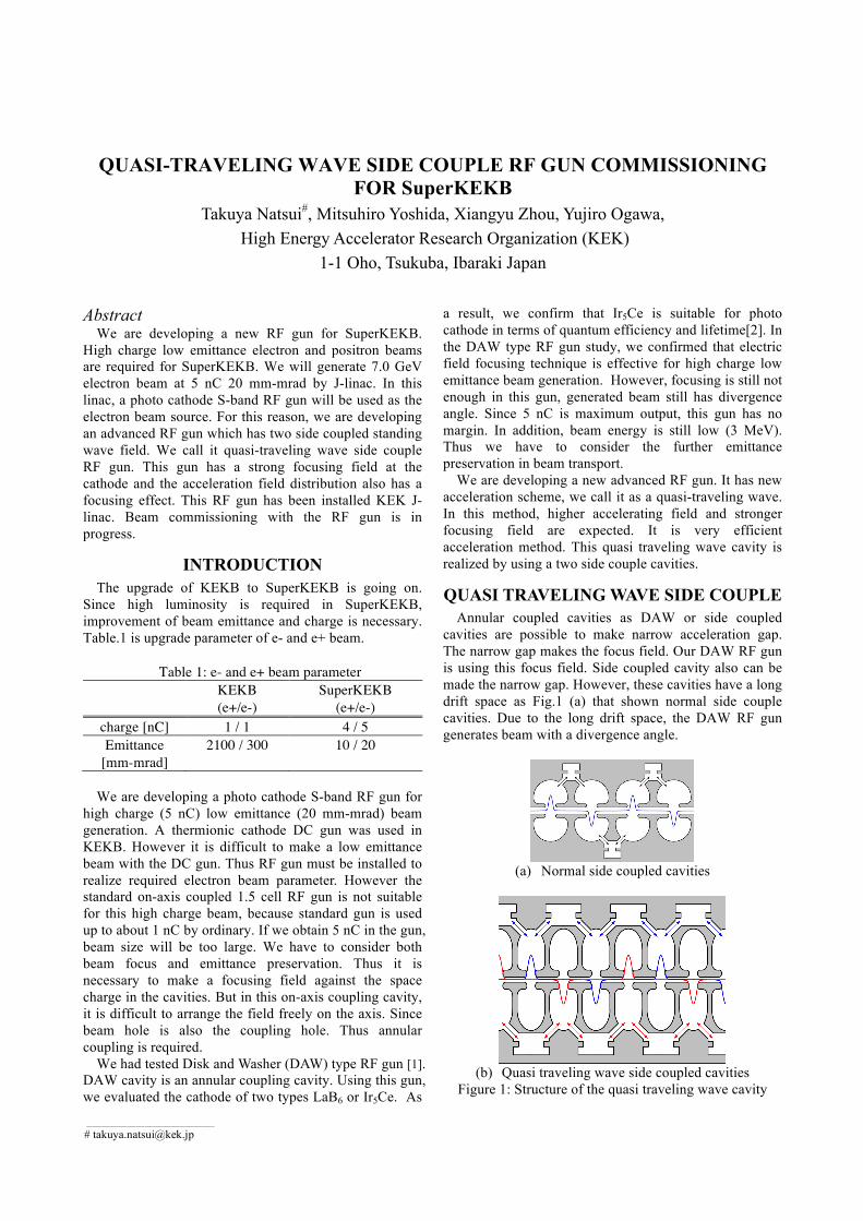
cavities are possible to make narrow acceleration gap. The narrow gap makes the focus field. Our DAW RF gun is using this focus field. Side coupled cavity also can be made the narrow gap. However, these cavities have a long drift space as Fig.1 (a) that shown normal side couple cavities. Due to the long drift space, the DAW RF gun generates beam with a divergence angle.
(a) Normal side coupled cavities
(b) Quasi traveling wave side coupled cavities
Figure 1: Structure of the quasi traveling wave cavity
One solution is to use two standing wave cavities. If two side coupled cavities are arranged staggered, we obtain a double standing wave field as Fig.1 (b). These two standing wave side coupled cavities are independent electromagnetically. If we feed RF power with !/2 phase difference, acceleration field is similar to traveling wave to accelerated beam. Since two side coupled cavities are possible to place on the same axis, a quasi-traveling wave can be realized. Quasi-traveling wave can realize very efficient beam acceleration and focusing.
CAVITY DESIGN The first cavity of RF gun is most important for beam
quality. Since beam energy of cathode cell is still low, space charge affects beam size and emittance. First cavity should be designed to have strong focus field. However nonlinear component of the strong focus field causes emittance growth. In addition, we must avoid the electric field concentration at the cavity surface. In the 2D cathode cell cavity design, a lot of parameters were searched. The parameters were optimized through the beam tracing simulation. SUPREFISH and GPT (General Particle Tracer) calculation code were used for calculation.
Fig.2 is whole cavities structure design and electric field (SUPERFISH result). This RF gun has total of seven acceleration cavities. These are divided into two standing wave structure of 3 and 4 side coupled cavities respectively. There are no couplings to next cavity on the axis.
Figure 3 shows the beam tracking simulation for 5 nC beam charge result; emittance is 5.5 mm-mrad: beam size is 0.4 mm (standard deviation) at exit of RF gun (z = 250 mm). In the Fig.3, we can find that the beam size becomes gradually smaller in the RF gun. This is caused by the focusing electric field of RF gun without additional magnetic field. Beam energy will be 11.5 MeV with 20 MW RF input. The energy spread is 0.6 %. These results satisfy the requirement of our application.
In addition, we confirm that this gun can generate 10 nC beam generation by calculation; emittance is 10 mm-mrad; beam size is 1.2 mm; energy spread is 1 %. It is enough margins.
Figure 2: Designed RF gun cavities (SUPERFISH calculation result)
We used CST MICROWAVE STUDIO for 3D cavity design. Figure 4 is the calculation result of the regular cell of a side coupled cavity. The acceleration mode and coupling mode are adjusted to be same frequency. Coupling value k is 3 %. This gun has two standing wave cavities; we designed two types coupler as shown Fig.5. Figure 6 shows the whole cavity shape. The side couple cavities of the two standing wave cavities are mounted as 90 degrees in the azimuthal angle. It has two ports for RF
feed. We use 90 degree hybrid for RF feed. New compact 90 degree hybrid was developed. It will be mounted RF gun directly.
Figure 3: Beam tracking simulation result
(a) Accelerating made (b) Coupling mode
Figure 4: regular cell cavity calculation result
Figure 5: Two type couplers and calculation result
Figure 6: Whole cavity shape
FABRICATION AND INSTALL The RF gun has double side coupled cavities. These
cavities make complex shape. Thus normal manufacturing way that separate cells for acceleration cavity and coupling cavity is not suitable for this gun. We chose to make integrated cell. A cell has both accelerating cavity and coupling cavity as shown Fig.7. In these cells, brazing will be easier. Compact 90 degrees hybrid was developed for this gun. The hybrid is fitted on the gun directly.
This new RF gun was installed to KEK injector in September 2013. A thermionic cathode DC gun was replaced with the RF gun at A1 sector for beam commissioning. Figure 8 is photo of installed RF gun.
Figure 7: Photo of manufactured cells and after brazing
Figure 8: Installed RF gun
BEAM COMMISSIONING Beam commissioning was started autumn 2013.
Ytterbium fiber and disk laser system was used for the RF gun[3]. Fundamental of this Yb laser system is 1030 nm. Its fourth harmonics is injected to RF gun. Maximum beam charge of 5.1 nC has been confirmed with this laser system and Ir5Ce cathode.
Figure 9: Beam size measurement for Q scan
Q-scan emittance measurements were performed using a 30 µm thickness alumina fluorescent plate. Beam size was measured as Fig.9. Beam energy was 25 MeV at the plate. As a result, normalized emittance is 32.7 ( 3.1) mm-mrad in horizontal and 10.7 ( 1.4) mm-mrad in vertical at beam charge of 1 nC. This high emittance result will be due to the instability of the laser.
Positron beam commissioning was also started by using the RF gun beam for primary beam as shown Fig.10 [4].
Figure 10: BPM signal of electron and positron beam
CONCLUSION High charge and low emittance electron and positron
beam are required for SuperKEKB injection. An RF gun will be used for electron beam source. Required electron beam parameter is 5 nC and 20 mm-mrad. Thus we are developing a new photo cathode S-band RF gun for high charge and low emittance beam generation. The annular coupled cavity is suitable for this beam generation. Quasi-traveling wave RF gun was developed for SuperKEKB.
The quasi-traveling wave is a new acceleration scheme. The RF gun has two standing wave cavities that are side coupled cavities. Two side coupled cavities on same axis can realize quasi-traveling wave. It is suitable for the high charge and low emittance beam generation.
The RF gun was already installed A1-sector of KEK injector. Maximum beam charge was 5.1 nC. This beam is being also used for positron primary. Beam emittance was measured by Q scan method. As a result, normalized emittance is about 30 mm-mrad at 1 nC. Laser stabilization and higher output is required for more accurate measurement.
Gun for SuperKEKB” TUPPD057, IPAC12, Louisiana, USA, 2012.
[2] Daisuke Satoh et al., “Development of Better Quantum Efficiency and Long Lifetime IrCe Photocathode for High Charge electron RF Gun” MOPFI023, IPAC13
[3] Xiangyu Zhou et al., “Ytterbium Fiber and Disk Laser of RF Gun for SuperKEKB” WEPME061, IPAC14
[4] Takuya Kamitani et al., “SuperKEKB Positron Source Construction Status” MOPRI004, IPAC14