Page 1
International Journal of Science and Research (IJSR) ISSN: 2319-7064
SJIF (2019): 7.583
Volume 10 Issue 3, March 2021
www.ijsr.net Licensed Under Creative Commons Attribution CC BY
Quasiturbine Rotary Engine Stator Confinement
Profile Computation and Analysis
Gilles Saint-Hilaire Ph.D.1, Roxan Saint-Hilaire MBA
2, Ylian Saint-Hilaire M.Sc.
3,
Françoise Saint-Hilaire M.Let4
1Quasiturbine Académie, Montréal, Québec, Canada
Abstract: Among the most frequent questions asked about the Quasiturbine « QT » are: Why is a central differential needed? And how
is the stator confinement profile calculated? These are strategic elements reluctantly discussed by the inventors in the past 20 years.
Many are convinced that computing the correct confinement profile of the Quasiturbine rotor is not simple task, and the purpose of this
paper is to help understanding the matter and the underling characteristics. Unaware of the real difficulty, some are reporting
elementary solution attempts, but missing ways to control their exactitude, they are so far neither reliable, nor precise enough.
Quasiturbine confinement profile is discussed in a USA patent, and exact solutions are graphically presented as the « Saint-Hilaire
skating rink profile » (named after the physicist who first made exact calculations) by analogy to well-known sport skating rink. As a
first hint, notice that ellipses are not acceptable solutions, which are far from unique due to undetermined nature of the Quasiturbine
rotor. Contrary to circular constraints of piston engine and conventional turbine, the asymmetrical « multi degrees of freedom » concept
of the Quasiturbine offers a wide variety of underlying innovative design options, and working characteristics.
Note: This scientific disclosure does not constitute permission for commercial manufacturing.
Keywords: Quasiturbine; Rotary engine; Steam engine; Air engine; Rotary pump
1. Quasiturbine rotor description
The QT rotor is a deformable chain of 4 interconnected
blades by pivoting hinge at their ends [1], [2]. As such, there
is no rotor constraint or limitation to its square and lozenge
shape, and holding it by hands reveals a feeling somewhat
like a mechanical Jell-O! [3]. This rotor can be placed within
a close fit circular confinement, where it can rotate freely in
square configuration. Notice the 4 constant and equal volume
chambers between each pivoting blade and the internal
circular wall, which then does not suggest much interest to
the device. Now imagine the closed fit circular confinement
profile (stator) being squished in a bench vice (or anvil) and
permanently deformed, then outer blades chambers would
have different sizes during rotation (assuming it would
rotate), while opposed chambers across the rotor center
would have same volumes.
Photo A – The Quasiturbine « QT » with carriages rotor
arrangement www.quasiturbine.com base on optional
manufacturing design.
2. Understanding the rotor geometry
2.1 Rotor is not confined
Opposed pivots are co-linear with the center of the rotor, and
always at the same distances and move in and out the same
way. Both sets of opposed pivots moves along orthogonal
axis crossing at the rotor center, and stay at 90 degrees apart
at all time and for all configurations (simplifying
calculations).
During a rotation, the rotor becomes either in square or full
diamond configurations 8 times, which defined 8 reference
points and curve sections of 45 degrees each, of which 2 will
need to be fed by seed curves (see below) for complete
contours.
Figure 1: The Quasiturbine rotor becomes either in square or
full diamond configurations 8 times per rotation, defining 8
points of reference and sections for contour. Notice the top
and bottom pivots moved inward in diamond configuration,
in contrast with the square configuration and its circle broken
line (PivEcc = 1). The central circular track supporting the
mid blade roller is shown in the first quadrant.
Paper ID: SR21313004008 DOI: 10.21275/SR21313004008 872
Page 2
International Journal of Science and Research (IJSR) ISSN: 2319-7064
SJIF (2019): 7.583
Volume 10 Issue 3, March 2021
www.ijsr.net Licensed Under Creative Commons Attribution CC BY
The pivots have a substantial physical size, and consequently
the pivots’ center itself cannot be in contact with the stator
confinement wall. It is the pivot outside circle (or its
contained seal) which touches the stator confinement wall.
No matter the degree of rotor deformation (configuration), its
center of masse stays immobile at the center of the rotor. It is
said to be perfectly balanced at all angle and rotational
speed.
Not confined, this rotor geometry is unstable in rotation: It
could be initially stable in square configuration, but as soon
as a set of opposed pivots moves a bit away from the rotor
center, centrifugal force will expel these 2 pivots outward,
while the orthogonal ones will sort of implode inward.
While rotating, an external force (from the stator
confinement wall or elsewhere?) will be needed to guide the
rotor back toward the square configuration. One could
further conceive a central mechanical device to guide the
pivots in respect to the stator wall, but this would not be
relevant to the present calculation method of the stator
confinement profile.
While rotor is confined
Close elliptic-like stator fit is necessary to confine the rotor
and provide contour guidance forces to pivots’ outside
diameter (and its contained seal) to bring back the rotor from
4 diamond-to-square configurations, 4 times per rotation.
While rotating, the overall QT rotor size changes as the loz-
enge configuration (deformation) and the seals angle
touching the stator confinement profile, which could means
variations in the blades’ pivots circuit. Smooth stator
confinement profile does not guaranty smooth needed
movement of the relatively massive blades and their blades’
pivots. Consequently, calculations will have to determine
first the smooth blades’ pivots circuit, which will provide by
enlargement the shape of the stator confinement profile.
Photo B – The Quasiturbine medallion offers a simple view,
while hiding underlying complexity and characteristics
From the rotor characteristics, the stator confinement profile
must be symmetrical point by point only through the rotor
center, which means that the rotor shape is not necessarily
symmetrical through the X and Y axis. Said otherwise, the
stator shape in any 180 degrees arc can be identically copied
180 degrees forward or half, which does not mirrored it
across X or Y axis.
3. QT rotor size, limit and guidance
Prerequisites: Blade length, 2 seed curve sections and
eccentricities
As detailed below, the contour shapes are marked by 8
reference points 45 degrees apart, defining 8 contour
sections, 2 of which being feed by seed curves. During
rotation, most parameter values change continuously at all
time, but the following are kept constant:
For the rotor, the designed blade length « L » extending
from one pivot center to the other (a dimensional number),
which define the sizes of the circular (Eccentricity = 1)
blades’ pivots circuit (square lozenge circle broken line on
graphs) and everything else; and
The blades’ pivots circuits « eccentricity form factor »
(Ecc, a pure number), which from circular (Ecc = 1)
blades’ pivots circuit (square lozenge circle broken line, on
graphs) dictates the longest X axis (proportional to (L x
Ecc) / sqrt(1 + Ecc2) ), and the minimum Y axis
(proportional to L / sqrt(1 + Ecc2) ), two derived
dimensional numbers useful when comparing several
blades’ pivots circuits to one another. There is equivalence
between square lozenge circle deformation (delta R = %)
and blades’ pivots circuit eccentricity (PivEcc).
The 8 reference points 45 degrees apart.
For the stator confinement profile, distinct size and
eccentricity (ConfEcc) result directly from enlarging the
blades’ pivots circuit to take into account the pivot
diameter, the contour seals and their geometric orientation
during rotation.
The two selected seed curves (not necessarily
symmetrical), one in each interlaced group.
These parameters determine the computation needs for all
points of reference, and elsewhere in-between points as
univocally defined by seed curves (see below). Notice that
the stator confinement profile will have its own (ConfEcc)
eccentricity.
In order to have a smooth running machine, one must
consider the movement of the masses within the rotor. The
best way to insure smooth movement of the QT pivoting
blades is to insure smooth movement of the blades’ pivots
circuit.
The criteria for smooth blades’ pivots circuit movement
(where the masses are) will require careful monotone
progression, and geometric continuity in between seed
curves sections, both simultaneously in position in
tangential angle. This smoothness may have some impacts
on the stator confinement profile due to minor rotor size
variation during rotation.
This criteria imposes the matching points between blades’
pivot circuit sections to fit both in radially and also
angularly. Furthermore, as considered design eccentricity
Paper ID: SR21313004008 DOI: 10.21275/SR21313004008 873
Page 3
International Journal of Science and Research (IJSR) ISSN: 2319-7064
SJIF (2019): 7.583
Volume 10 Issue 3, March 2021
www.ijsr.net Licensed Under Creative Commons Attribution CC BY
increases, the stator profile will initially look like a sort of
ellipse, but pass over a certain PivEcc limit, the stator will
have an inflexion zone at its shorter diameter ends (like 2
ellipses stretching apart), which may require special
attention in several applications.
A criteria on eccentricity inflexion limit in order to
locate an inflexion of the stator confinement profile, a
zone of constraint that not all mechanical designs may
consider.
Finally, the 8 reference points of the blade’s pivot circuit
are not sufficient to determine the intermediary curve
sections (and consequently the stator confinement profile).
To raise the indetermination of the blades’ pivot circuit,
one needs to provide 2 seed curve sections. Designers are
free to impose these curves sections in-between reference
points to meet their own design characteristics. These seed
curves do not have to be symmetrical nor identical, and by
seed definition are exact blades’ pivot circuit solutions,
once selected.
No such seed curves are needed for the stator confinement
profile, as it is determined by the blades’ pivot circuit. This
indetermination is an important asymmetrical « multi
degrees of freedom » particularity of the Quasiturbine
concept to permit a wide variety of underlying innovative
design options and working characteristics, this is in addition
to mechanical dimensions and proportions freedom shared
with the well-defined geometric circular constraints of piston
engine and conventional turbine.
About the pivot design
Once the rotor is taken apart, the blades are obviously more
massive at one end (the « HEAD » in preferential direction
of rotation, where the seal is located) and less heavy on the
other end (the « TAIL » while rotating). Once assembled, the
complementary pivot geometry makes all the pivots having
the same weights and balance. The HEAD side (with the
seal) may at first look as the male hinge, but its under harm
is definitively a female receptacle. Reciprocally, the TAIL
side appears as the female hinge, but its under faced is
definitively a male insert. Both ends of the blade have
simultaneously male and female characteristics for most
symmetrical design, providing robustness and leak-proof
options.
4. Establishing the reference points
Observations on the blades’ pivots circuit
During rotor movement, the pivots move along an ellipse-
like circuit, where two extreme rotor geometry
configurations occur alternatively: One being the full
diamond rotor extension, and the other the perfectly square
rotor arrangement.
While in full diamond extension, 4 exact pivots positions of the rotor are easily determined from the imposed
eccentricity PivEcc of the blades’ pivots circuit (stator radius
being enlarged by pivot circle diameter and seals), allowing
determination of a distinct eccentricity ConfEcc for the stator
confinement profile.
While in perfect square configuration, 4 exact pivots
positions are straight forward at the pivots corners of the
square lozenge (on circle in broken line).
Be careful, coordinates of 8 exact reference points are
known for the blades’ pivots circuit, but without any in-
between circuit detail information. Who will provide the
detail movement in-between the reference points? The
designers themselves, as they are free to impose (not one but
2, and no more) curve sections, in-between points of the
blades’ pivots circuit, which do not have to be symmetrical,
nor identical, and such seed curves are by definition exact
solution. Notice that rotor contour seals are not involved in
the blades’ pivot circuit calculation, but are in the stator
confinement profile.
Observations on the stator confinement profile
No seed curve is needed for the stator confinement profile, as
it is determined by the blades pivots circuit. During confined
rotation, the pivots diameter (ot its containd seal) moves in
contact with an ellipse-like stator profile, as full diamond
rotor extension and perfectly square rotor arrangement.
While in perfect square configuration, 4 exact stator
positions are straightforward from the pivot diameter at the
corner of the lozenge in square arrangement.
In full diamond extension, 4 exact stator contact
reference points are easily determined from the imposed
eccentricity of the blades’ pivots circuit (by radius addition
of pivots diameters and seals), allowing determination of a
different eccentricity ConfEcc for this stator confinement
profile.
At this point for the stator confinement profile, coordinates
of 8 exact reference points are known, and detail information
in-between will be provided from the blades’ pivot circuit
once its calculation is completed.
For both blades’ pivots circuit and stator confinement
profile, coordinates of a total of 16 reference points are
known which are most valuable before initiating exact detail
computation. The coordinates of these reference points are
exactly symmetrical, both across rotor central point, and
mirror across X and Y axis. It is the in-between seed curves
that make de blades’ pivot circuit, and consequently (with
seal orientations add up) the stator confinement profile not
mirror symmetrical.
Off-radius seal orientation: An additional rotor confinement profile asymmetry comes
from the seals orientation in relation to the local radius,
which results from the fact that each pivoting blade holds a
seal at only one end. This large pivot diameter contains a
nearly immobile stator contour seal, which seal extend
exactly radially only in the rotor square configuration (where
the rotor has its maximum overall dimension). In diamond
rotor extension, one can notice on the drawings that the seals
touch the stator slightly off the X and Y axis (contact axis
being in counter rotation to one another), while these seals
are exactly co-linear at 45 degrees diagonal in square
configuration.
Paper ID: SR21313004008 DOI: 10.21275/SR21313004008 874
Page 4
International Journal of Science and Research (IJSR) ISSN: 2319-7064
SJIF (2019): 7.583
Volume 10 Issue 3, March 2021
www.ijsr.net Licensed Under Creative Commons Attribution CC BY
Figure 2: Pivots coordinates of the rotor blades are shown in
square and extended diamond configuration. 8 reference
points for the blade’s pivot circuit, and as many for the stator
confinement profile by enlargement. Notice that these
reference points are symmetrical, both across center and X
and Y axis, while the seed curves and calculated solutions
are not necessarily mirrored symmetrical
Circular central supporting track for mid-blade roller is
shown in quadrant I. The circle broken line is the exact no
eccentricity (PivEcc = 1) circular blades’ pivot circuit.
Depending of the blade orientation during the rotation, the
seal off-radius orientation reduces overall rotor size by
leading ahead the movement (in large radius profile section)
and lagging behind the movement (in short radius profile
section). The effect of this « off-radius seal orientation »
generates small sizes radius reduction within the stator wall
(none at 45 degrees, maximum at 0 and 90 degrees)
spreading asymmetrically over 90 degrees each.
Consequently, there is a relatively small preferential
direction of assembly of the rotor within the stator. Once
properly paired, the QT rotor can turn indifferently in both
directions.
5. Modified Ellipse MOD8 to Fit 8 Points
Comment on parametric trigonometric ellipse formula
Trigonometric parametric ellipse equation looks simple:
X = Rx * sin(tau) and
Y = Ry * cos(tau)
(tau) being the parameter (not the actual point angle)
This is rigorously true for cycle where Rx = Ry, (tau) being
then the angle of the R radius. As the eccentricity increases,
the Radius angle is not (tau) any more. All parameters (tau)
provide coordinate of points which are on the perfect ellipse,
but such points are not at the (tau) radius angle. Phase out
between true Radius angle and tau may reach 5 to 8 degrees
(increasing with eccentricity) in the range of simple QT
solutions. Providing careful radius angle correction, this
method is fine to get the perfect ellipse coordinates and
shape. For each eccentricity an equivalence table of radius
angle versus the tau parameter can be calculated with
sufficient precision by 4 or 5 iterations only.
Does ellipse fit through 8 known symmetrical points?
It would be great if the geometrical properties of the blades’
pivots circuit would coincide with ellipse geometrical
properties, otherwise ellipse shape will only fit through a set
of 4 symmetrical points. As obvious from previous
Quasiturbine disclosures, early attempt shows that ellipse
cannot fit the blades’ pivots circuit, neither the stator
confinement profile. Fit can be pretty close at small
eccentricity, but becomes rapidly useless for design purpose.
Modifying the perfect ellipse to fitting 8 symmetrical
points
Ellipse can easily be made to pass by the ends of the long
and the short diameter axis, but offers no flexibility to reach
any other arbitrary symmetrical coordinates midway.
Drawing shows that the Quasiturbine rotor characteristics do
not match the ellipse characteristics. Practically, perfect
ellipses do not extend far enough in their 45 degrees corners
areas to fit any QT rotor solution; unless forcing the ellipse
to pass by the X45, Y45, and R45.
Figure 3: Even for most simple case, perfect ellipse is
shown to be unable to simultaneously fit at once 8 reference
points, while the MOD8 modified ellipse does (without
detail in-between reference points). An extra pair of
parameters « PivC(X;Y) » must be introduced into the ellipse
equation, to stretch the ellipse corner shape while preserving
it near the X and Y axis. Will also fit the stator confinement
profile with appropriate » ConfC(X;Y) » parameters.
To better fit (approximate) the Quasiturbine blades’ pivots
circuit needs, an extra pair of parameters « PivC(X;Y) »
could be introduced in the perfect ellipse equation (the C(X)
; C(Y) being the axis amplitude of the pivot circuit
corrections, possibly in the form of sin3(4 x theta) or
otherwise). If the correction match is done along the 45
degrees radius, then PivC(X) = PivC(Y), usually in the range
between 0 to 3 % of the radius, to stretch the ellipse corner
shape (while preserving the full diamond main axis
coordinates), and to allow fitting at once through the entire 8
reference points coordinates of the blades pivots circuit. The
same MOD8 ellipse approximation function would also fit
with the stator confinement profile, providing an appropriate
set of « ConfC(X;Y) » parameters is used. MOD8 ellipse
offers exact fit of reference points, but no exact curve in-
between. Exact blades’ pivots circuit and stator confinement
profile computation will have to provide solution in-between
these exact points matched by MOD8.
Paper ID: SR21313004008 DOI: 10.21275/SR21313004008 875
Page 5
International Journal of Science and Research (IJSR) ISSN: 2319-7064
SJIF (2019): 7.583
Volume 10 Issue 3, March 2021
www.ijsr.net Licensed Under Creative Commons Attribution CC BY
MOD8 limitation to near symmetrical and no inflexion
MOD8 is a very valuable analytical tool for the most obvious
(and current) QT cases. As the perfect ellipses, the MOD8
ellipses are mirrored through X and Y axis, and consequently
symmetrical. They could be useful approximations where the
2 seed curves are complementary symmetrical one another,
and generate near symmetrical blades’ pivots circuit and
stator confinement profile. They are not recommended to
approximate more advanced and complex asymmetrical and
inflexion QT geometries.
MOD8 ellipse is no attempt to get an exact Quasiturbine
blades’ pivots circuit, nor the stator confinement profile, but
is a simple mathematical approximation for purpose of
understanding and discussion. In symmetrical cases
considered in this paper, the modified MOD8 ellipses
radiuses in the 45 degrees area are exact ellipses values
extended by no more that 5 %. Notice that the modified
MOD8 ellipse shape and pair parameters for blades’ pivot
circuit are much different for the stator confinement profile.
6. Blades’ Pivot Circuit - Symmetrical Seed
Curves
Imposing seed curves to 2 groups of interlaced sections
The set of 16 reference points is not sufficient to determine
details solution in-between the points. Where are the in-
between detail data available? This is part of the
Quasiturbine multi-degrees of freedom concept not to
provide these details, and it is left to the designer to make his
own choices. Therefore, before initiating any computation at
the blades’ pivots circuit level, two inter-points « seed curves
sections » must be imposed, one and only one within each of
the 2 interlacing groups. Each proposed curve section will be
copied by symmetry across the rotor central point (no mirror
across X or Y axis), and later used by the mathematical rotor
pivots transform function to map the corresponding
orthogonal segments, for a total of 4 sections in each
interlaced group. Same will be done with the second
interlacing group, to complete the blades’ pivot circuit
calculation.
Notice that impose seed curve sectors are by definition exact
solution. Furthermore, this example shows that solutions are
far from being unique, but as many as you can propose seed
curves. Notice that these reference points are symmetrical,
both across center and X and Y axis, while seed curves and
seals orientations spoil the in-between mirror symmetry.
Comment on eccentricity versus circle deformation? The eccentricity is a necessary upfront value before
proceeding to exact calculation. Using an analytical function
like MOD8 to seed the Blades’ pivots circuit provides
upfront eccentricity from the equation. Another way to feed
the seed sections is to modify the (PivEcc = 1) pivots
lozenge circle (broken line on the graphs), by adding a radial
perturbation on it, in which case only the long X axis is
imposed, and not the short Y axis (needed to determine the
eccentricity). Fortunately, this shorter Y axis can be easily
calculated upfront by the rotor geometry in full extended
diamond configuration. This provides equivalence relation
between square lozenge circle deformation (delta R = %) and
blades’ pivots circuit eccentricity (PivEcc).
7. Rotor Pivots Transform Function
The rotor configuration change must occur simultaneously
along two orthogonal X and Y axis. For every two opposed
points coordinates set on the blades’ pivots circuit, the rotor
define two coordinates set on its orthogonal axe, which are
the mapping of the first set. This is the « rotor pivots
transform function » one needs to determine the exact
blades’ pivot circuit in the top and the bottom area of the
graphs. Notice that this function is reversible from the
mapped coordinates set to the original coordinates set, and
that the rotor pivots transform function returns 2 coordinates
set (one up, one down), both along the actual orthogonal
axis.
Figure 4: For the blades’ pivot circuit, a simple set of 2 seed
curves which could be from MOD8 ellipse (not anymore an
approximation once seed selected), shown with their
symmetrical copy across the center. The QT multi-degrees of
freedom concept leaves designer with « seed freedom of
choice ». All done now for initiating the top and bottom
blades’ pivot circuit calculation through the mathematical
rotor pivots transform function. The circle in broken line is
the exact no eccentricity (Ecc = 1) circular blades’ pivot
circuit
8. Exact Blades’ Pivot Circuit Computation
Exact blades’ pivot circuit solutions will require computation
through the mathematical « rotor pivots transform
function », where movement of the pivot along some curve
sections will be imaged (mapped) in another section to
entirely defined the current blades’ pivot circuit. Previous
observations established a set of 8 exact reference points
coordinates that pivots circuit must go through, and similarly
for the stator confinement profile, for a total of 16 control
reference points, most valuable before initiating exact detail
computation. Rotor contour seals are not involved in the
blades’ pivot circuit calculation, but will later in the stator
confinement profile.
Paper ID: SR21313004008 DOI: 10.21275/SR21313004008 876
Page 6
International Journal of Science and Research (IJSR) ISSN: 2319-7064
SJIF (2019): 7.583
Volume 10 Issue 3, March 2021
www.ijsr.net Licensed Under Creative Commons Attribution CC BY
Figure 5: Shows half of the exact blades’ pivot circuit
calculated result for one seed curve (here from the modified
MOD8 ellipse Quadrant I), and its symmetrical through
center (Quadrant III), with its rotor pivots transformed
(Quadrant II), and the symmetrical solution (Quadrant IV).
The other interlaced group seed curve can be imposed in any
of the free interspace, and calculated the similar ay, for a
complete blades’ pivot circuit. Notice that exact solution
goes strictly through the 8 reference points. The circle
broken line is the no eccentricity (PivExc. = 1) circular
circuit.
One must first get the solution for the blades’ pivots circuit.
The 8 in-between sections of the blades’ pivots circuit form
2 groups of 4 interlaced curve sections each; where in each
group, one in-between section must be seed by a proposed
seed curve. By definition, all proposed seed curves and their
symmetrical across the rotor central point are part of the
exact blades’ pivot circuit solution. From one seed curve
section, the three other sections can be determined. Similar
procedure applied to the second group of interlaced sections,
where seed curve (or part thereof) can be on any still
available group.
Two sections (and their symmetries) are left to be computed
for the blades’ pivots circuit? Each group of 4 in-between
curves has 2 known as the seed curves and their symmetrical
across the rotor central points; the 2 sections left are also
symmetrical, so only one in-between curve needs to be
computed by the rotor pivots transform function. Similar
computation needs to be carried on the second group of 4 in-
between curves. Consequently, the « rotor pivots transform
function » need to be applied only twice (once per group) for
the blades’ pivot circuit.
9. Exact Stator Confinement Profile
Computation
Stator confinement profile
Once the blades’ pivot circuit is known, there is no need to
apply the « rotor pivots transform function » to get the
stator confinement profile, as it is mainly an enlargement.
Also, practical consideration imposes the contour seal tip to
extend somehow (10 to 20 % of pivot radius) outside the
large pivot diameters.
Off-radius seal orientation Not only asymmetries come from the non-symmetrical seed
curves, but some seals asymmetry also results from the fact
that each pivoting blade holds seal at one end only, where a
larger pivot diameter contains a nearly immobile stator
contour seal [4], [5], which seal extend exactly radially only
at the rotor square configuration (where the rotor has its
maximum overall dimension).
Figure 6: With the seed curves (again from the modified
MOD8 ellipse), here are the calculated exact blades’ pivots
circuit and stator confinement profile (as an enlargement of
the blades’ pivots transforms). Due to off-radius seals
orientations, notice the contact point of the seals with the
stator are not exactly at 0 and/or 90 degrees, radius being
slightly closer to one another in quadrant I and III.
Depending of blade orientation during the rotation, the seal
off-radius orientation reduces overall rotor size by leading
ahead of movement (in large radius profile section) and
lagging behind the movement (in short radius profile
section). The effect of this off-radius seal orientation
generates small size reductions within the stator wall, each
centered on zero and 90 degrees area.
Figure 7: Even with perfectly symmetrical blades’ pivots
circuit, flipping the rotor shows blades’ seal orientation
asymmetries that a stator cannot fit both at once. Clockwise
rotation of the stator and the rotor must then be properly
paired to allow the QT to turn indifferently in both
directions.
Paper ID: SR21313004008 DOI: 10.21275/SR21313004008 877
Page 7
International Journal of Science and Research (IJSR) ISSN: 2319-7064
SJIF (2019): 7.583
Volume 10 Issue 3, March 2021
www.ijsr.net Licensed Under Creative Commons Attribution CC BY
Preferential direction of rotor assembly It is obvious that the QT rotor can turn indifferently in both
direction, but does the rotor have a preferential direction of
assembly in relation to the stator? In full diamond rotor
extension, one can notice that the seals touch the stator
slightly off the X and Y axis (contact axis getting closer to
one another), while these seals are exactly co-linear on the
45 degree diagonal in square configuration. This is because
the QT pivoting blades carry asymmetrically a seal at only
one end, stator symmetry being perfect only at 45 degrees.
These off-radius seal orientation corrections on the stator
impose a small preferential direction of assembly of the rotor
within the stator, even for the perfectly symmetrical blades’
pivots circuit and while barely noticeable on the graph. This
is further true for all complex stator shapes, but once
correctly paired within the stator, the QT rotor can turn
indifferently in both directions.
Important to notice that the seal orientation stator radius
reductions, each spread around 0 and 90 degrees, are stator
shapes adjustment that the seals must follow to insure that
the pivots stay on the optimum circuit in the most smoothly
matter. These seal orientation are significant enough to
impose a preferential direction of assembly. Consequently,
the rotor and the stator need to be paired accordingly for the
rotor to turn freely in both directions.
10. Quasiturbine QT.6LSC Circuit and
confinement comparaison
Referring to the small 1.5 kW Quasiturbine manufactured as
air-steam motor under the model QT.6LSC, here are the
parameters comparison for exact solution of the blades’ pivot
circuit and the stator confinement profile. Notice the
modified MOD8 ellipse different pair parameters for each
best fit. Parameters are given for both the blades’ pivots
circuit on the left, and the stator confinement profile on the
right:
Notice that the maximum stator radius (on the right) is the
maximum blades’ pivots circuit radius (on the left)
increased by the pivot circle radius and the needed seals
space tolerance.
Eccentricity of the blades’ pivots circuit of PivEcc = 1,301
is reduced to ConfEcc = 1,251 on the larger stator
confinement profile.
MOD8 ellipse modification pair parameters goes from
PivC(X=3,470 %; Y=3,470 %) for the blades’ pivots
circuit to ConfC (X=1,700 %; Y=3,440 %) for the stator
confinement profile.
11. What if eccentricity is further increased?
This would offer still more options for innovation and
specific challenges. Then, the blades’ pivot circuit and the
stator confinement profile show an inflexion in the shortest
diameter area. Computation method does still apply,
however the inflexion point may become in itself an obstacle
to the passage of the pivoting blades, surface of which may
need to be depleted in concave shape in order to make room
for the blade to move across the stator inflexion area,
somewhat as the Wankel engine (Similarities end there!).
Central blade supporting track and rollers may also be design
in an appropriate way.
Modified MOD8 ellipse (even if it still does go through the 8
reference points) will not fit correctly the inflexion contour.
However MOD8 is far from being useless, as it can provide
interesting seed curves options, which are part of the exact
solution by definition. Exact circuit and profile computation
become however an absolute necessity for practical
application.
Figure 8: Modified MOD8 ellipse is non-reliable in-between
reference points at such a high eccentricity, but provides
interesting seed curves options, which are part of the exact
solution, once selected. Notice that a pivoting blade concave
surface is needed to transit across the inflexion. The
computation method is still valid at high eccentricity. Notice
that Wankel rotary engine cannot avoid this inflexion, while
QT can!
12. Complex Seed Curve and Asymmetry
The square lozenge circle (broken line on graph) is the
Paper ID: SR21313004008 DOI: 10.21275/SR21313004008 878
Page 8
International Journal of Science and Research (IJSR) ISSN: 2319-7064
SJIF (2019): 7.583
Volume 10 Issue 3, March 2021
www.ijsr.net Licensed Under Creative Commons Attribution CC BY
spherical trivial solution for the blades’ pivots circuit. A
symmetrical deformation of this basic circle leads to ellipse-
like type of situation. To illustrate the effect and results, a set
of 2 different seed curves are here considered next one
another (they do not have to be symmetrical, nor identical),
in the extremities area of the maximum long axis. For
comparison, these 2 seed curves are selected to produce the
same eccentricity at blades’ pivot circuit level, as well as
equivalent at the stator confinement profile level (remember
that seed curves are exact solutions by definition):
Symmetrical Seed curve Case-1:
A section of the lozenge circle Radius increased up to 12 %,
by the cos3(2 x théta) function.
Asymmetrical Seed curve Case-2:
A section of the lozenge circle Radius is increased up to 12
%, by the cos1(2 x théta), and made asymmetrical by the +/-
(80%) sin2(4 x théta) function (+ in an interlaced group, - in
the other).
Figure 9: To illustrate the seed curves freedom of choice,
and corresponding possibility, here are 2 examples of blades’
pivots circuit seed curves (not from MOD8 this time) with
same 8 reference points. Notice that one is highly
asymmetric. Stator confinement profile being an
enlargement, it does not need seed curve of its own. The
circle in broken line is the exact no eccentricity (PivEcc = 1)
circular blades’ pivot circuit
Notice that these seed curves do not come from an analytical
equation like MOD8 (where eccentricity is known), but are
perturbations imposed on the pivots lozenge circle (broken
line on the graph) fixing only the long X axis (small Y axis
need to be calculated from de rotor full diamond
configuration to provide eccentricity). The second proposed
seed curve is an asymmetric case showing that computed
solution may potentially extend the circuit further than the
maximum large X axis diameter, while the maximum
diameter is not considered for stator eccentricity (see 22
degrees area). It does confirm that any combination of seed
curves (say in the positive Y) can be selected with any
combination curves in the negative Y.
Several other curve types can be used for alteration of the
lozenge circle, like linear and or quadratic deformations.
This kind of asymmetric profile could offer different
physical characteristics of the Quasiturbine at intake
compared to exhaust. So many different solutions are
possible, each with their own physical properties.
Figure 10: The exact solution of the asymmetric Case-2 is
presented to illustrate the complex asymmetrical seed curves
effects, with the 8 reference points for the blades’ pivots
circuit, as well as those for the stator confinement profile.
Asymmetry can generate off-X axis large oblique non-
orthogonal diameter (look the 22 degrees area).
This example shows again that ellipses are not compatible
solutions, and that solutions are far from being unique. In
complex case, the surface of the blade may limit the
clearance of its own stator while moving within the said
stator. Furthermore, this example shows that solutions are far
from being unique, being as many as one can propose seed
curves!
The complex blades’ pivot circuit seed curve is a way to
modify the geometrical Quasiturbine characteristics, but one
may also consider modifying the size and proportion of the
blade’s supporting track, rollers and external blades’ pivots
diameters, as described in a previous patent. Present
calculation method still applied.
Figure 11: Modifying the blade’s supporting track, rollers
and external blades’ pivots diameters are other geometrical
alternatives to explore different Quasiturbine characteristics.
Knowing that the QT pumps 8 chamber volumes per rotation
(4 on each side), here is an example where the flow per
revolution exceeds the size of the machine! This stator shape
well fit the name « Saint-Hilaire skating rink profile ».
13. Applying Computation to Torque and
Power
The present method is a general tool to explore numerous
Quasiturbine design parameters. While having the geometric
Paper ID: SR21313004008 DOI: 10.21275/SR21313004008 879
Page 9
International Journal of Science and Research (IJSR) ISSN: 2319-7064
SJIF (2019): 7.583
Volume 10 Issue 3, March 2021
www.ijsr.net Licensed Under Creative Commons Attribution CC BY
characteristics on hand, why not go on further? [6]
Calculation of internal chamber volume would lead to
compression and expansion ratio and to fluid flow across the
machine. Assuming constant fluid pressure within the
Quasiturbine, radial and tangential forces could be calculated
providing torque and power output. This calculation method
is also suitable for design component sensibility analysis,
and can help to select proper intake and exhaust ports
positioning, as well as the location of side contour seals
location, and stator contour bolts positioning, as well as
central differential design insertion.
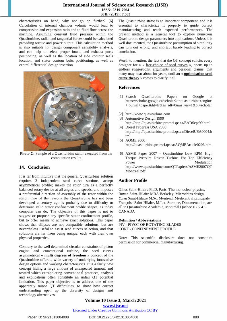
Photo C: Sample of a Quasiturbine stator executed from the
computation results
14. Conclusion
It is far from intuitive that the general Quasiturbine solution
requires 2 independent seed curve sections; accept
asymmetrical profile; makes the rotor turn as a perfectly
balanced rotary device at all angles and speeds; and imposes
a preferential direction of assembly of the rotor within the
stator. One of the reasons the Quasiturbine has not been
developed a century ago is probably due to difficulty to
determine valid stator confinement profile shapes, as today
computer can do. The objective of this paper is not to
suggest or propose any specific stator confinement profile,
but to offer means to achieve exact solutions. This paper
shows that ellipses are not compatible solutions, but are
nevertheless useful to assist seed curves selection, and that
solutions are far from being unique, each with their own
physical properties.
Contrary to the well determined circular constraints of piston
engine and conventional turbine, the seed curves
asymmetrical « multi degrees of freedom » concept of the
Quasiturbine offers a wide variety of underlying innovative
design options and working characteristics. It is a fairly new
concept hiding a large amount of unexpected turnout, and
toward which extrapolating conventional practices, analysis
and explications often constitute an unfair QT potential
limitation. This paper objective is to address one of the
apparently minor QT difficulties, to show how correct
understanding open up the diversity of designs and
technology alternatives.
The Quasiturbine stator is an important component, and it is
essential to characterize it properly to guide correct
manufacturing and reach expected performances. The
present method is a general tool to explore numerous
Quasiturbine design parameters into applications. Unless it is
well documented, the Quasiturbine presumption of simplicity
can turn out wrong, and shortcut barely leading to correct
conclusion.
Worth to mention, the fact that the QT concept solicits every
designer for a « free-choice of seed curves », opens up to
endless suggestions, arguments and personal claims, that
many may hear about for years, until an « optimisation seed
curve theory » comes to clarify it all.
References
[1] Search Quasiturbine Papers on Google at
https://scholar.google.ca/scholar?q=quasiturbine+engine
+journal+paper&hl=fr&as_sdt=0&as_vis=1&oi=scholar
t
[2] http://www.quasiturbine.com
[3] Automotive Design 1999
http://http://quasiturbine.promci.qc.ca/EADSept99.html
[4] Diesel Progress USA 2000
http://http://quasiturbine.promci.qc.ca/DieselUSA0004.h
tml
[5] AQME 2006
http://quasiturbine.promci.qc.ca/AQMEArticle0206.htm
l
[6] ASME Paper 2007 - Quasiturbine Low RPM High
Torque Pressure Driven Turbine For Top Efficiency
Power Modulation
http://www.quasiturbine.com/QTPapiers/ASME2007QT
Montreal.pdf
Author Profile
Gilles Saint-Hilaire Ph.D. Paris, Thermonuclear physics,
Roxan Saint-Hilaire MBA Berkeley, Microchips design,
Ylian Saint-Hilaire M.Sc. Montréal, Meshcentral principale,
Françoise Saint-Hilaire, M.Let. Sorbone, Documentation, are
all in Quasiturbine Académie, Montréal Québec H2K 4J9
CANADA
Definition / Abbreviations
PIV - PIVOT OF ROTATING BLADES
CONF - CONFINEMENT PROFILE
Note: This scientific disclosure does not constitute
permission for commercial manufacturing.
Paper ID: SR21313004008 DOI: 10.21275/SR21313004008 880