QUESTION CODE NO. 791 CIVIL ENGINEERING IV SEMESTER (M SCHEME) 31042 – TRANSPORTATION ENGINEERING PREPARED BY Dr. P. PERIYASAMY STAFF IF: 11761001 LECTURER (SG) / CIVIL GOVT. POLYTECHNIC COLLEGE FOR WOMEN COIMBATORE – 641 044.
Transcript
QUESTION CODE NO. 791
CIVIL ENGINEERING
IV SEMESTER (M SCHEME)
31042 – TRANSPORTATION ENGINEERING
PREPARED BY
Dr. P. PERIYASAMY
STAFF IF: 11761001
LECTURER (SG) / CIVIL
GOVT. POLYTECHNIC COLLEGE FOR WOMEN
COIMBATORE – 641 044.
PART – A
N.B: Q.No.8 is compulsory & each question carries two marks.
1.Camber is the cross slope provided across the road to raise middle of the road surface to
drain off rain water from road surface. The camber given is either a parabolic, elliptic or
straight line shape in the cross section
2.The main objective of reconnaissance survey is to examine the general character of the area
for the purpose of determining the most feasible route a mong the routes.
3.The rails should provide continuous and level surface for the movement of trains.
The rails should provide a smooth and uniform surface and should bear the heavy loads
transmitted through the wheels.
The rails should bear lateral stresses due to braking and thermal stresses as well.
The rails should transmit the load to the ballast formations through sleepers.
(Any two points - 2 marks)
4. To regulate the safe arrival and departure of trains from station yards.
To maintain a safe distance between trains running on the same line in the same direction.
To ensure safe and efficient shunting operations.
To ensure safety of cross traffic at level crossings.
At any other location where visual indication as to the situation ahead is necessary to be
conveyed to engine drivers . (Any two points – 2 marks )
5.For distribution of the load from superstructure to substructure to reduce intensity of
pressure within the safe limits of the materials of construction. It should be capable of
accommodating maximum expected deck moment and rotation with least possible resisting
force.
6. Turntble is used for watering,fuelling and reversing the direction of engines.
7.Economic span is the span for which the costs of super structure and substructure are equal.
Thus the economic span of bridge makes the overall cost of the bridge is to be a minimum.
8.In order to counter act the effect of centrifugal force and to reduce the tendency of the
vehicle to overturn or skid, the outer edge of the pavement is raised with respect to inner
edge, by providing a transverse slope throughout the length of the horizontal curve. This
transverse inclination to the pavement surface is known as super elevation or cant or banking.
The super elevation “e” is expressed as the ratio of the height of outer edge with respect to
the horizontal width.
e = v2/ 225 R
PART – B
N.B: Q.No. 16 is compulsory & each question carries three marks.
9.It should be free from being submerged during floods and thus should be available for safe
movement of traffic at all times.
It should be provided with easy gradient.
It should contain intelligently erected traffic signs and should make sufficient provisions for
the safety of pedestrians and vehicles.
It should grant various amenities to road users such as grass verges, sufficient lighting,
watering and fuelling places at regular intervals, shady avenues, parking facilities in city
areas, etc.
It should possess good alignment, directness and visibility.
The curves along the road should be properly designed and they should be free from blind
corners.
The formation of road, either natural or prepared, should be stable enough to carry the
foundation and traffic load. (Any three points – 3 marks )
10. To increase compressive strength irrespective of moisture content.
To increase the resistance to softening action of water.
To reduce shrinkage and swelling due to water content.
To increase shear strength and resistance to punching shear. ( Any three points – 3 marks
11. It should be able to maintain proper gauge.
It should provide sufficient bearing area for the rail.
It should have sufficient weight for stability.
It should facilitate the fitting for the easy removal or replacement of rails whenever needed.
It should provide adequate area of contact between ballast and rails.
It should be elastic, resilient and shock absorbing.
It should accommodate the packing of ballasts easily, effectively and quickly.
It should not get damaged easily on working. ( Any three points – 3 marks )
12.A marshalling yard is a place where goods wagons received from different centres are
sorted out and placed in the order of detachment at different stations.
Marshalling yards are also serving as distributing centres. Empty wagons are also kept in
marshalling yards and despatched to different stations as and when required by
them.(Explanation – 2 marks /Fuctions – 1 mark)
13.Scour :It is the removal of bed soil due to high velocity of the stream. Scour will be occurs
when the bed velocity of the stream is higher than the limiting velocity.(1 ½ marks )
Afflux:Where the flow of water in stream or river meets with any obstruction, the water level
will be rises. The difference in levels of the water surfaces between the upstream and the
downstream sides of the bridge is called Afflux ( 1 ½ marks )
14.Signalling consists of the systems, devices and means by which trains are operated
efficiently, tracks are used to a maximum extent maintaining safety of passengers, staff and
the rolling stock. It includes the use and working of signals, points, block instrument and all
other equipment.
15.Stability against geological disturbances
Land degradation and soil erosion
Destruction and denudation of forest
Interruption an disturbance to drainage system
Aestheticconsiderations
Siltation of water resources (any three points – 3 marks )
16.If the track of the wheels rest flat on the rails, there will be lateral movement of the axle.
This results in the damage to the inside faces of the head of the rails. This is prevented by
sloping the tread at a slope of 1 in 20. This sloping of the wheels from the vertical axis is
known as coning of wheels (1 ½ marks )
. coning flange
rails sleeper
(1 ½ marks )
PART - C
Each question carries ten marks :
17(a) The safe and efficient operation of vehicles on the road depends very much on the
visibility of the road ahead of the driver. Thus the geometric design of the road should be
done such that any obstruction on the road length could be visible to the driver from some
safe distance ahead so that the driver can stop the vehicle before the obstruction. This
distance is said to be the sight distance.
TYPES OF SIGHT DISTANCE: Sight distance available from a point is the actual
distance along the road surface, over which a driver from a specified height above the
carriage way has visibility of stationary or moving objects. Three sight distance situations
are considered for design
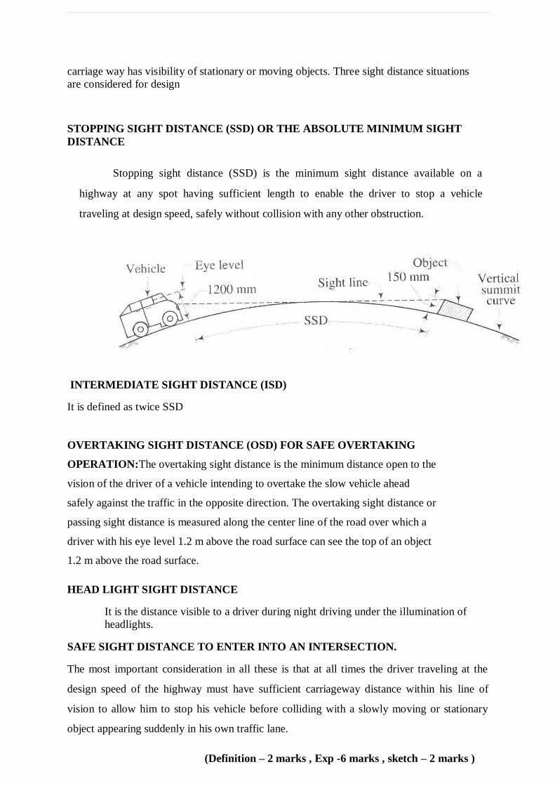
STOPPING SIGHT DISTANCE (SSD) OR THE ABSOLUTE MINIMUM SIGHT
DISTANCE
Stopping sight distance (SSD) is the minimum sight distance available on a
highway at any spot having sufficient length to enable the driver to stop a vehicle
traveling at design speed, safely without collision with any other obstruction.
INTERMEDIATE SIGHT DISTANCE (ISD)
It is defined as twice SSD
OVERTAKING SIGHT DISTANCE (OSD) FOR SAFE OVERTAKING
OPERATION:The overtaking sight distance is the minimum distance open to the
vision of the driver of a vehicle intending to overtake the slow vehicle ahead
safely against the traffic in the opposite direction. The overtaking sight distance or
passing sight distance is measured along the center line of the road over which a
driver with his eye level 1.2 m above the road surface can see the top of an object
1.2 m above the road surface.
HEAD LIGHT SIGHT DISTANCE
It is the distance visible to a driver during night driving under the illumination of
headlights.
SAFE SIGHT DISTANCE TO ENTER INTO AN INTERSECTION.
The most important consideration in all these is that at all times the driver traveling at the
design speed of the highway must have sufficient carriageway distance within his line of
vision to allow him to stop his vehicle before colliding with a slowly moving or stationary
object appearing suddenly in his own traffic lane.
(Definition – 2 marks , Exp -6 marks , sketch – 2 marks )
17(b)(i)Gradient is the rate of rise or fall along the length of the road with respect to the
horizontal (1 mark)
Ruling gradient, limiting gradient, exceptional gradient and minimum gradient are
some types of gradients. (1 mark)
The ruling gradient or the design gradient is the maximum gradient with which the designer
attempts to design the vertical profile of the road. This depends on the terrain, length of the
grade, speed, pulling power of the vehicle and the presence of the horizontal curve. (1 mark)
This gradient is adopted when the ruling gradient results in enormous increase in cost of
construction. On rolling terrain and hilly terrain it may be frequently necessary to adopt
limiting gradient. But the length of the limiting gradient stretches should be limited and
must besandwiched by either straight roads or easier grades. (1 mark)
Exceptional gradient are very steeper gradients given at unavoidable situations.
Theyshould be limited for short stretches not exceeding about 100 metres at a stretch. In
mountainous and steep terrain, successive exceptional gradients must be separated by a
minimum 100 metre length gentler gradient. At hairpin bends, the gradient is restricted to
2.5%. (1 mark)
b(ii) To provide for aesthetic enhancement of the project corridors
To reduce the impacts of air pollution and dust, as trees and shrubs are known to be natural
sink for air pollutants.
To provide much needed shade on glaring hot roads during summer.
To reduce the impact of ever increasing noise pollution caused due to increase in number of
vehicles.
To arrest soil erosion at the embankment slopes
Prevention of glare from the headlight of incoming vehicles.
Climatic amelioration,
Moderating the effect of wind and incoming radiation
To define the ROW especially, to highlight sharp horizontal curves during night
( any five points – 5 marks)
18. (a)WBM Consist of clean, crushed aggregates mechanically interlocked by rolling and
bonding together with screening, binding material where necessary, and water laid on a
properly prepared subgrade/sub-base/base or existing pavement, as the case may be and
finished in accordance with the requirements of the specifications and in close conformity
with the lines, grades, cross-sections and thickness as per approved plans or as directed by the
Engineer.
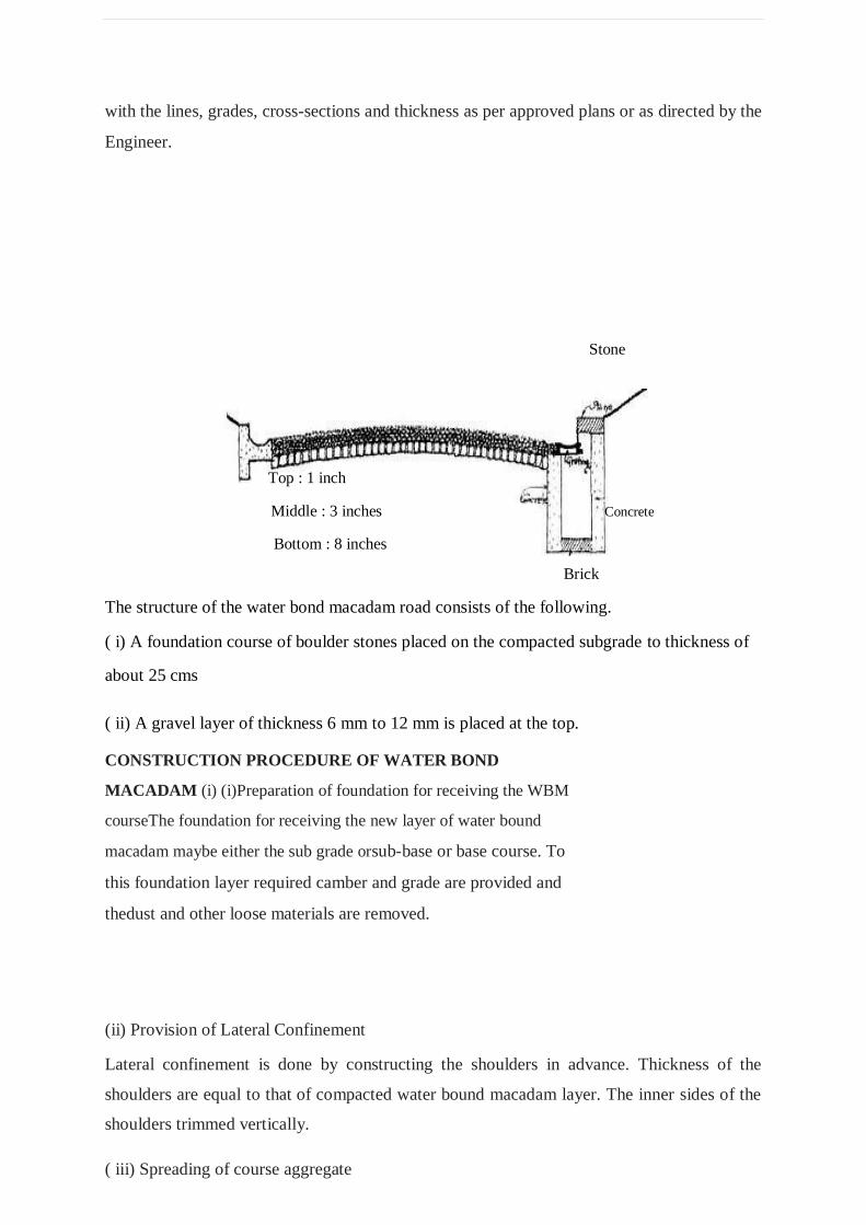
Stone
Top : 1 inch
Middle : 3 inches Concrete
Bottom : 8 inches
Brick
The structure of the water bond macadam road consists of the following.
( i) A foundation course of boulder stones placed on the compacted subgrade to thickness of
about 25 cms
( ii) A gravel layer of thickness 6 mm to 12 mm is placed at the top.
CONSTRUCTION PROCEDURE OF WATER BOND
MACADAM (i) (i)Preparation of foundation for receiving the WBM
courseThe foundation for receiving the new layer of water bound
macadam maybe either the sub grade orsub-base or base course. To
this foundation layer required camber and grade are provided and
thedust and other loose materials are removed.
(ii) Provision of Lateral Confinement
Lateral confinement is done by constructing the shoulders in advance. Thickness of the
shoulders are equal to that of compacted water bound macadam layer. The inner sides of the
shoulders trimmed vertically.
( iii) Spreading of course aggregate
The coarse aggregates which are stored along the road are spread uniformly and evenly upon
the
prepared base in required quantities. The aggregate should be spread to proper profile by
using
templates placed across the road about 6 m apart.
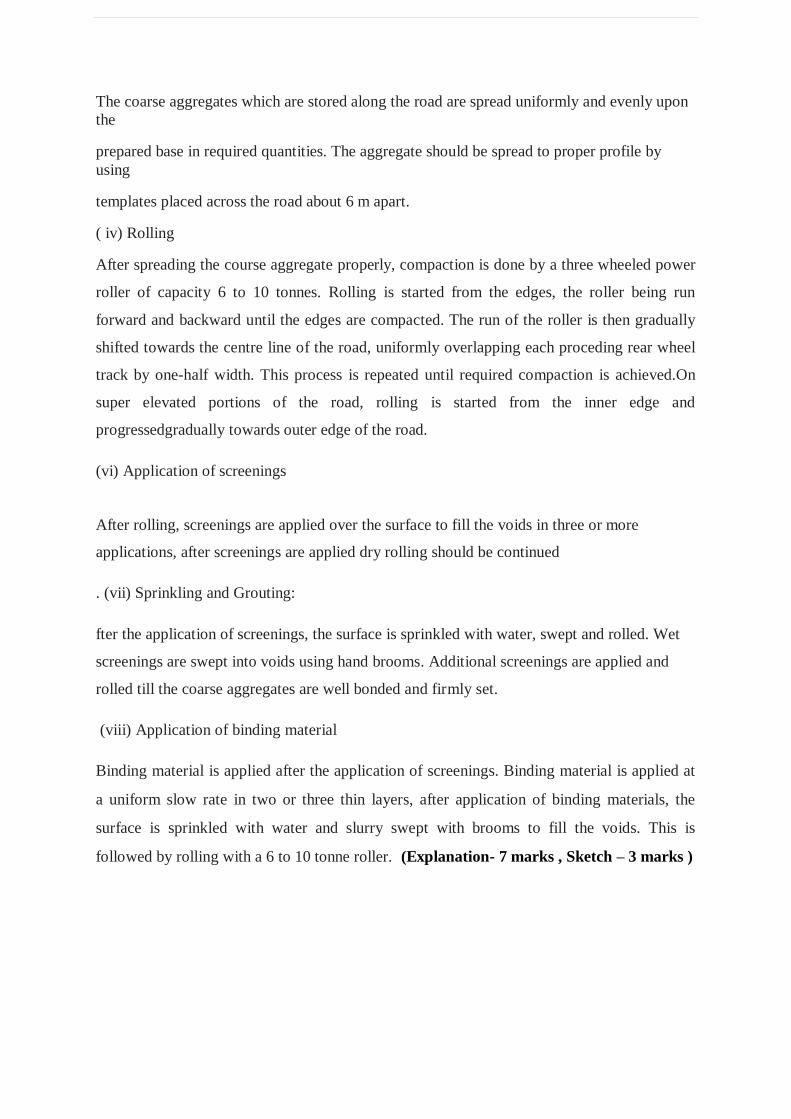
( iv) Rolling
After spreading the course aggregate properly, compaction is done by a three wheeled power
roller of capacity 6 to 10 tonnes. Rolling is started from the edges, the roller being run
forward and backward until the edges are compacted. The run of the roller is then gradually
shifted towards the centre line of the road, uniformly overlapping each proceding rear wheel
track by one-half width. This process is repeated until required compaction is achieved.On
super elevated portions of the road, rolling is started from the inner edge and
progressedgradually towards outer edge of the road.
(vi) Application of screenings
After rolling, screenings are applied over the surface to fill the voids in three or more
applications, after screenings are applied dry rolling should be continued
. (vii) Sprinkling and Grouting:
fter the application of screenings, the surface is sprinkled with water, swept and rolled. Wet
screenings are swept into voids using hand brooms. Additional screenings are applied and
rolled till the coarse aggregates are well bonded and firmly set.
(viii) Application of binding material
Binding material is applied after the application of screenings. Binding material is applied at
a uniform slow rate in two or three thin layers, after application of binding materials, the
surface is sprinkled with water and slurry swept with brooms to fill the voids. This is
followed by rolling with a 6 to 10 tonne roller. (Explanation- 7 marks , Sketch – 3 marks )
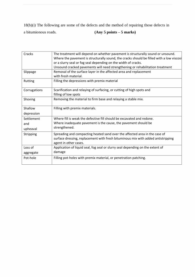
18(b)(i) The following are some of the defects and the method of repairing those defects in
a bitumionous roads. (Any 5 points – 5 marks)
Cracks The treatment will depend on whether pavement is structurally sound or unsound. Where the pavement is structurally sound, the cracks should be filled with a low viscosity binder or a slurry seal or fog seal depending on the width of cracks. Unsound cracked pavements will need strengthening or rehabilitation treatment
Slippage Removal of the surface layer in the affected area and replacement with fresh material.
Rutting Filling the depressions with premix material
Corrugations Scarification and relaying of surfacing, or cutting of high spots and filling of low spots
Shoving Removing the material to firm base and relaying a stable mix.
Shallow
depression
Filling with premix materials.
Settlement
and
upheaval
Where fill is weak the defective fill should be excavated and redone. Where inadequate pavement is the cause, the pavement should be strengthened.
Stripping Spreading and compacting heated sand over the affected area in the case of surface dressing, replacement with fresh bituminous mix with added antistripping agent in other cases.
Loss of
aggregate
Application of liquid seal, fog seal or slurry seal depending on the extent of damage
Pot-hole Filling pot-holes with premix material, or penetration patching.
b(ii)It can, be designed more accurately for load distribution.
It does not develop corrugations and hence, it grants noiseless surface.
It has good visibility at night due to colour contrast.
It has low cost of maintenance
It has low tractive resistance which diminishes the cost of running of vehicles.
It has more useful life than road of any other type of construction.
It is dustless and has no internal attrition.
It is not unduly slippery. ( any five points 5 marks )
19. (a)(i)Functions of ballast :. ( any 3 points- 2 ½ marks )
To provide a suitable foundation and hold the sleepers in their correct position.
To transmit and distribute the load from the sleepers to the formation.
To provide an easy means of correcting track levels and increase the elasticity of the track.
To protect the surface of formation from direct exposure to the sun, frost or rain.
To drain the water immediately and keep the sleepers in dry conditions.
To prevent the growth of vegetation inside the track.
To resist lateral, longitudinal and vertical displacement of the track.
The requirements of good ballast are listed below. ( any 3 points- 2 ½ marks )
It should maintain the shape.
It should have sufficient grip over the sleeper.
It should be sufficiently durable to resist the abrasion and weathering action.
It should be cheap and easily available.
It should provide lateral and longitudinal stability of the track.
It should easily drain water immediately.
It should be easily workable so that it can be easily laid.
It should not have any chemical action on rails and metal sleepers.
a(ii)According to position of joints the rail joints are of the following two types.
a. Square joints ( 2 ½ marks )
When a joint in one rail is exactly opposite to the joint in the other parallel rail, it is
called square joint. It is shown in Fig.3.14 (a). It is very common in straight tracks. But at
present, staggered joints are more favoured.
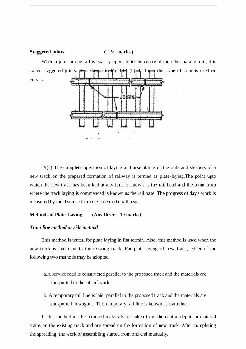
Staggered joints ( 2 ½ marks )
When a joint in one rail is exactly opposite to the centre of the other parallel rail, it is
called staggered joints. It is shown in Fig.3.14 (b). In India this type of joint is used on
curves.
19(b) The complete operation of laying and assembling of the rails and sleepers of a
new track on the prepared formation of railway is termed as plate-laying.The point upto
which the new track has been laid at any time is known as the rail head and the point from
where the track laying is commenced is known as the rail base. The progress of day's work is
measured by the distance from the base to the rail head.
Methods of Plate-Laying (Any three – 10 marks)
Tram line method or side method
This method is useful for plate laying in flat terrain. Also, this method is used when the
new truck is laid next to the existing track. For plate-laying of new track, either of the
following two methods may be adopted.
a.A service road is constructed parallel to the proposed track and the materials are
transported to the site of work.
b. A temporary rail line is laid, parallel to the proposed track and the materials are
transported in wagons. This temporary rail line is known as tram line.
In this method all the required materials are taken from the central depot, in material
trains on the existing track and are spread on the formation of new track, After completing
the spreading, the work of assembling started from one end manually.
10
2. Telescopic method
This method is very widely used in India. In this method, first of all a large central depot is
constructed near the junction of the existing railway or highway and the proposed railway
line. The manual force is divided as follows.
1. Material gangs 2. Linking-in-gangs 3. Packing-in-gangs.
a. Material gangs
These gangs unload the materials from the trains. Then they carry the materials to the rail
head and supply them to the linking-in-gangs. These gangs distribute sleepers, rails, fish-
plates, fish-bolts etc., at required places approximately.
b. Linking-in-gangs
These gangs mark the centre line of the proposed track and place the sleepers at required
places. Then the rails are placed on the sleepers. Successive rails are joined together by fish-
plates and bolts after leaving suitable expansion gaps. The expansion gaps are provided
equally using shim plates or liner plates. After joining, the rails are fixed to the sleepers.
c. Packing-in-gangs
After the rails have been fixed to the sleepers by the linking-in-gangs, packing-in-gangs will
correct the rails to the required level and gradients by packing earth/ballast below and around
the sleepers.
3. American method
This method requires special track laying equipment. This is a costlier method and hence not
followed in India. In this method, the entire track is assembled in the track laying workshops
and the entire unit is lifted up by heavy cranes and placed in position at rail base. The only
work which is done at site is the joining of rails by fish-plates and bolts. This method
facilitates fast laying of track and enables the throwing of track for service at the shortest
duration of time.
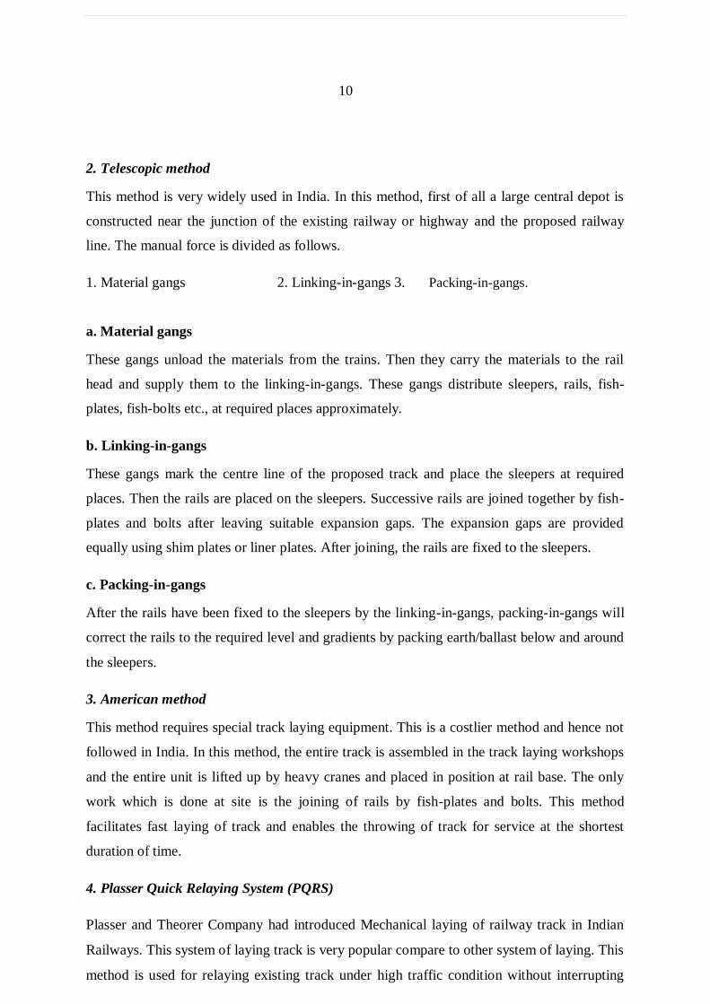
4. Plasser Quick Relaying System (PQRS)
Plasser and Theorer Company had introduced Mechanical laying of railway track in Indian
Railways. This system of laying track is very popular compare to other system of laying. This
method is used for relaying existing track under high traffic condition without interrupting
the flow of traffic. But this method requires the use of many tools and machinery and hence
comparatively costlier. This method facilitates laying new railway trackmechanically.
11
20.(a)The stations can be classified as
(Classify – 2 marks, Explanation –
marks)
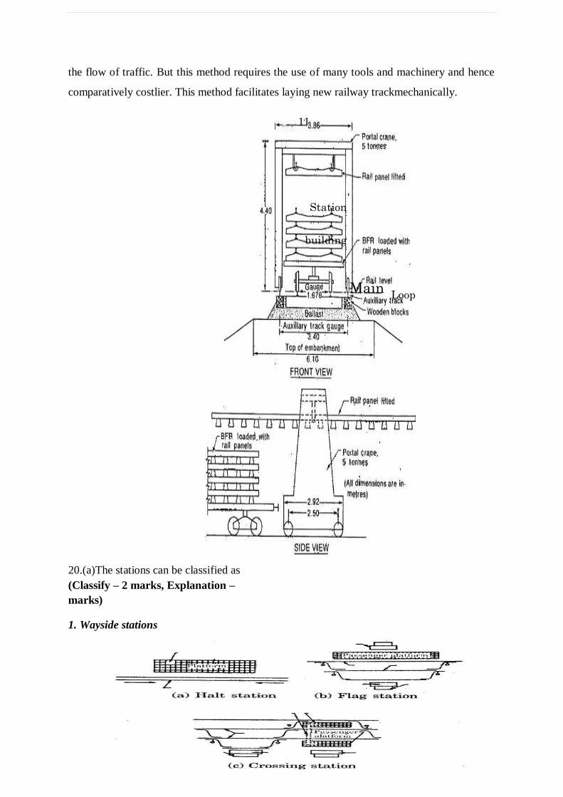
1. Wayside stations
Station
building
Main Loop
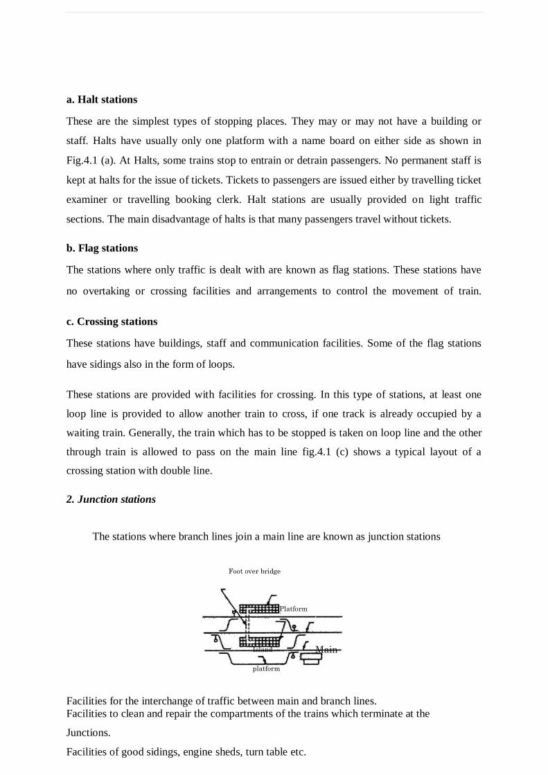
a. Halt stations
These are the simplest types of stopping places. They may or may not have a building or
staff. Halts have usually only one platform with a name board on either side as shown in
Fig.4.1 (a). At Halts, some trains stop to entrain or detrain passengers. No permanent staff is
kept at halts for the issue of tickets. Tickets to passengers are issued either by travelling ticket
examiner or travelling booking clerk. Halt stations are usually provided on light traffic
sections. The main disadvantage of halts is that many passengers travel without tickets.
b. Flag stations
The stations where only traffic is dealt with are known as flag stations. These stations have
no overtaking or crossing facilities and arrangements to control the movement of train.
c. Crossing stations
These stations have buildings, staff and communication facilities. Some of the flag stations
have sidings also in the form of loops.
These stations are provided with facilities for crossing. In this type of stations, at least one
loop line is provided to allow another train to cross, if one track is already occupied by a
waiting train. Generally, the train which has to be stopped is taken on loop line and the other
through train is allowed to pass on the main line fig.4.1 (c) shows a typical layout of a
crossing station with double line.
2. Junction stations
The stations where branch lines join a main line are known as junction stations
Foot over bridge
Platform
Island Main
platform
Facilities for the interchange of traffic between main and branch lines.
Facilities to clean and repair the compartments of the trains which terminate at the
Junctions.
Facilities of good sidings, engine sheds, turn table etc.
3. Terminal station
It is a station where a railway line or one of its branches terminates
Facilities required in a terminal station
Watering, cleaning, fuelling and servicing the engine.
Turn table for the change of direction of the engine.
Yards for dealing goods traffic (such as marshalling yard,
engine sheds, sidings etc.)
20(b)Principles of Interlocking ( 4 marks)
The essential properties of working of interlocking system are as follows:
It shall be possible to lower a signal for an approaching train only when the related line is
properly set and locked. Once signal is lowered, it shall be impossible to unlock the points.
Once signal is lowered for a train in line, it shall be impossible for loose wagons from other
point of the yard to obstruct the line.
It shall be impossible to any other signal for the admission of trains from opposite directions
to the same line at the same time.
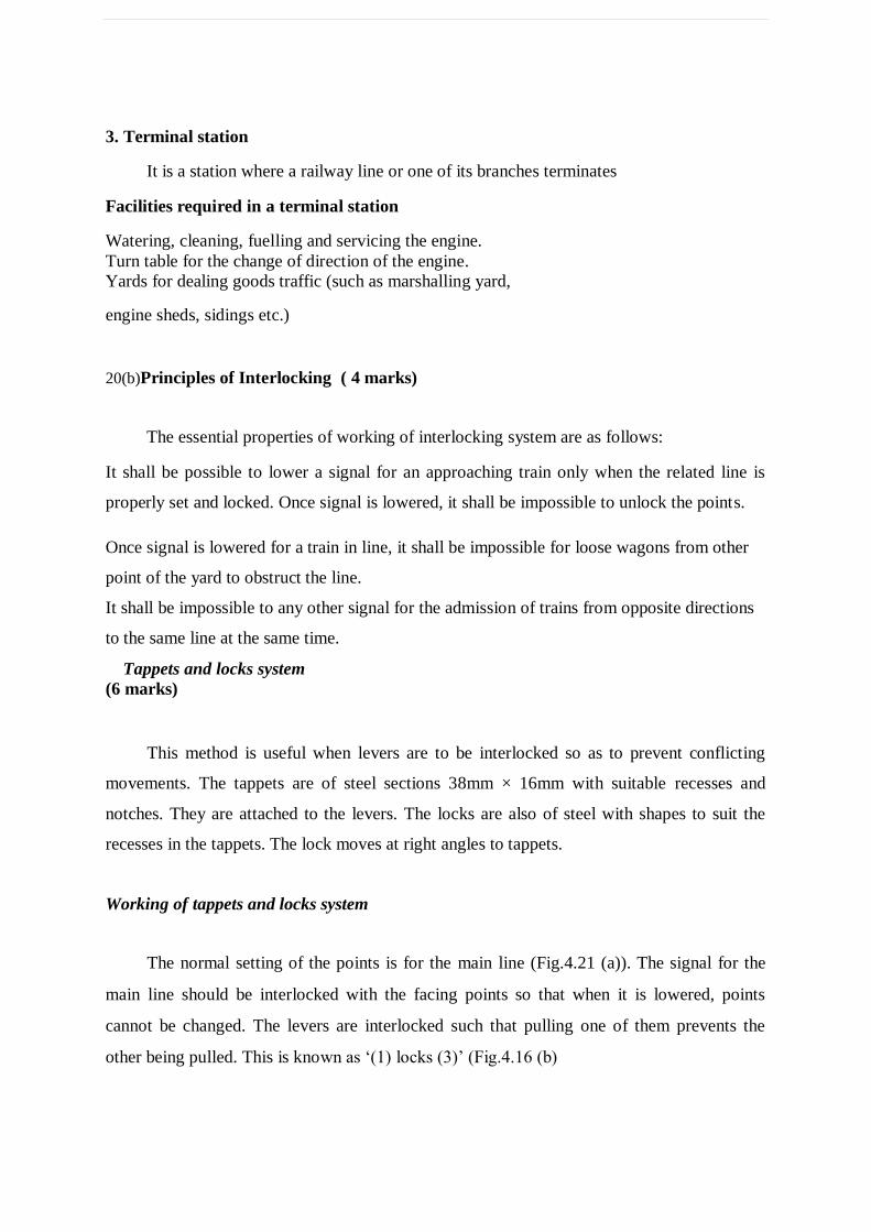
Tappets and locks system
(6 marks)
This method is useful when levers are to be interlocked so as to prevent conflicting
movements. The tappets are of steel sections 38mm × 16mm with suitable recesses and
notches. They are attached to the levers. The locks are also of steel with shapes to suit the
recesses in the tappets. The lock moves at right angles to tappets.
Working of tappets and locks system
The normal setting of the points is for the main line (Fig.4.21 (a)). The signal for the
main line should be interlocked with the facing points so that when it is lowered, points
cannot be changed. The levers are interlocked such that pulling one of them prevents the
other being pulled. This is known as ‘(1) locks (3)’ (Fig.4.16 (b)
Tappets and locks system
The loop signal should be interlocked with the facing points such that it cannot be
lowered unless the points are set for the siding. Also it cannot be lowered when the joints are
set for main line. Levers (2) and (3) are interlocked so that the lever (2) cannot be pulled
unless (3) has already been pulled. Conversely lever (3) can be restored to its normal position
only if lever (2) has already been restored to its original position. This is known as ‘(3)
release (2)’ or ‘(2) backlocks (3)’
The outer signal should be so interlocked with the routing signal that it cannot be lowered
until one of them is first lowered. When levers (1), (2) and (4) are interlocked so that lever (4)
cannot be worked unless lever (1) or (2) has already been worked
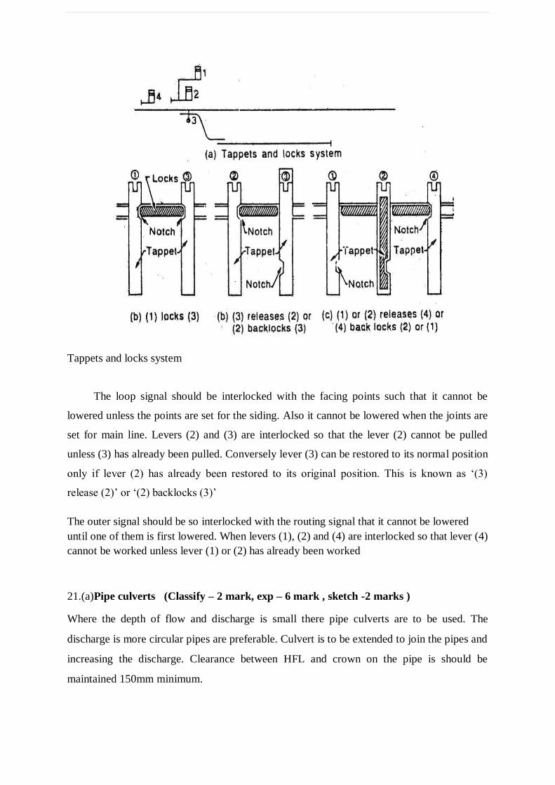
21.(a)Pipe culverts (Classify – 2 mark, exp – 6 mark , sketch -2 marks )
Where the depth of flow and discharge is small there pipe culverts are to be used. The
discharge is more circular pipes are preferable. Culvert is to be extended to join the pipes and
increasing the discharge. Clearance between HFL and crown on the pipe is should be
maintained 150mm minimum.
Bottom level of the pipe must laid below the ground level at 1/3 rd of diameter of
pipe. The diameter of seldom exceeds 1800 mm reinforced and cast iron pipes are used. In
case of 600mm stoneware and plain concrete pipes are used. Masonry pitching must be
constructed on the both upstream and downstream sides to protect the banks against scouring.
Pipes usually laid over 150mm thick layer of concrete and covered by earth cushion either
600mm thick for metal roads, or 1200 mm thick earthen roads. If cast iron pipes are provided
earth cushion is not required for sufficient depth. The RC pipes are laid by surrounding with
cement concrete at an angle of 450.The minimum interspaced between jointed pipes as
150mm. This space is concreted in relevant manner.
Box culverts
This type of culvert consist one or more square or rectangular openings made up of masonry
or RCC.Box culverts are very common. Stone slabs also used for small culverts. In soft soils,
where there is a possibility of scouring and bearing capacity of soil is poor, these culverts are
used.
RC box culverts are generally built upto 4m span. All the four sides of culverts are
generally built with same cross section and the same reinforcement is provided for the top
slab. Depending upon site condition earth cushion may be provided to reduce impact. Bottom
slab is to be extended 100mm on either side.
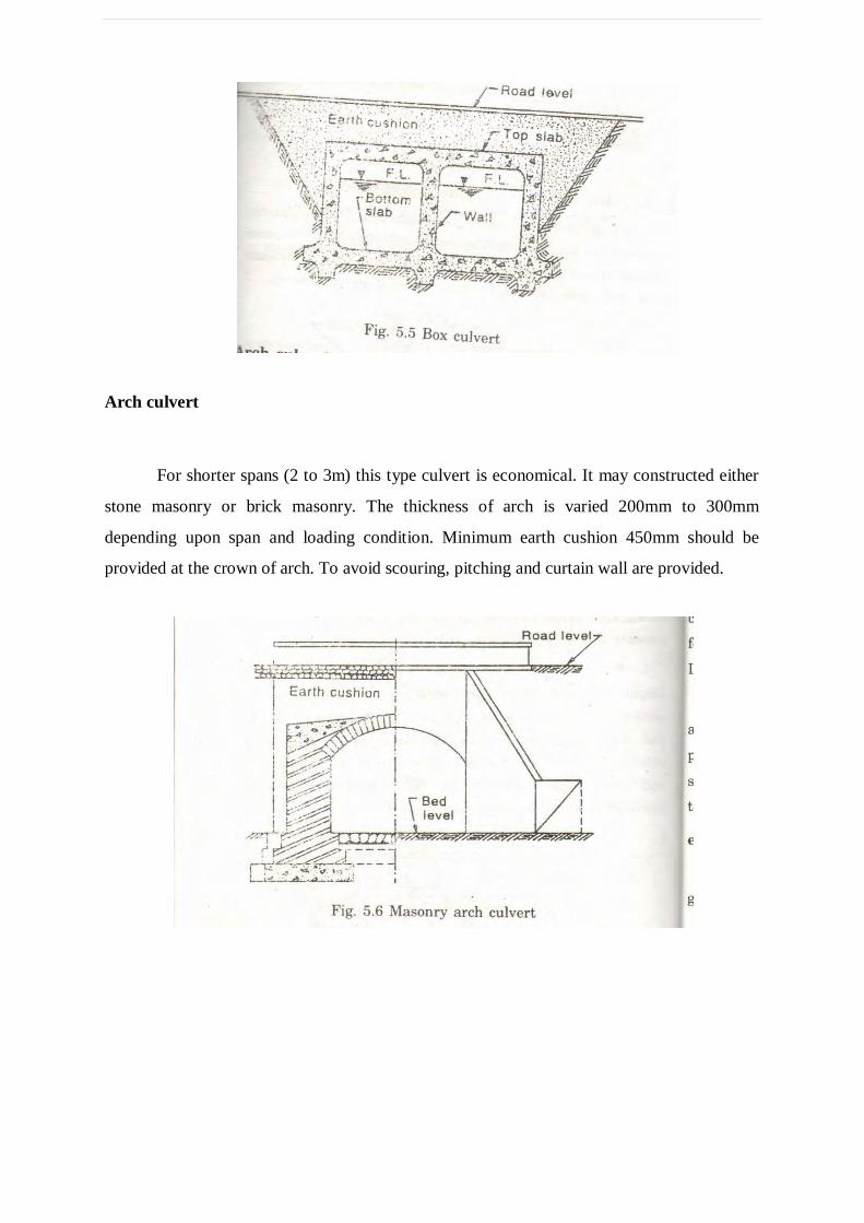
Arch culvert
For shorter spans (2 to 3m) this type culvert is economical. It may constructed either
stone masonry or brick masonry. The thickness of arch is varied 200mm to 300mm
depending upon span and loading condition. Minimum earth cushion 450mm should be
provided at the crown of arch. To avoid scouring, pitching and curtain wall are provided.
21.(b)Fixed bearing (type – 2 marks ,exp – 5 marks , sketch -3)
To prevent any longitudinal moment of the girders fixed bearings are provided. They are
suitable only for small spans up to 12m. They are classified as,
Shallow plate bearing
Deep base bearing
Laminated rubber fixed bearing
Cement mortar pad
Rocker-roller bearing
These are suitable for largest spans in these bearing the bottom shoe rest on the cylindrical
roller which roll on a number of rails placed over the masonry or cast steel block or steel
plate. This bearing allows free longitudinal as well as angular movements of the main girder
of the bridge connected to the top shoe.
Rocker bearing
These bearings are also suitable for larger spans, say more than 21 metres. This is similar to
the Roller-rocker bearings. It has a 20cm radius circular rocker pin placed between the top
and bottom shoes, having the same radius 2/3 rd of the circumference of the rockers are
covered by the shoes and saddle cover. The top shoe is inverted and the bottom shoe is
directly placed on the masonry or on steel block provided on the top of the masonry.
Rocker bearing with curved bottom
This bearing allows free longitudinal as well as angular movement to the bridge girder. In
this bearing, the upper portion is similar to the Rocker bearing. The bottom shoe has a
curved bottom surface.
`Knuckle bearing
This bearing allows only angular movements of the girder fixed on the top shoe. The top
shoe has a semi-circular concave surface and the bottom shoe has a semi-circular concave
surface both having the same radius.
Sliding plate bearing
It consists of a sole plate fixed to the bottom of the girder of the bridge and rests on a wall
plate. The wall plate is rigidly connected to the masonry or bed block by bolts in such a way
that the sole plate is made free to slide over the wall plate by providing slotted holes in the
sole plate. Thus the sliding plate bearing allows longitudinal expansion or contraction due to
the variations in temperature or live loads etc.,
Sole plate on curved bed plate bearing
This type of bearing is useful where the sole plate is in the girder bridge. The sole plate is
fixed on the girder of the bridge and rests on a curved bed plate fixed in the masonry.