18
Quick Manual Inward Gliding Door

Quick Manual Inward Gliding Door

2
Index
1. System Description/Components ....................................................................................................... 3
1.1 Product diagram ........................................................................................................................... 3
1.2 Overview Door Mechanism .......................................................................................................... 4
1.3 Components ................................................................................................................................. 4
2. Fitting the door System ...................................................................................................................... 5
2.1 Mounting the door shafts and door shaft supports ..................................................................... 5
2.2 Adjusting door shafts and door shaft supports ........................................................................ 7
2.3 Mounting the door wings ............................................................................................................. 8
2.4 Mounting the guiding bracket ...................................................................................................... 9
2.5 Link the fork joint of the cylinder ............................................................................................... 10
2.6 Mounting portal U-profile rubber and portal strips ................................................................... 11
3. Mechanical adjustment of the door system .................................................................................... 12
3.1 Adjust the side seals with the side of aperture .......................................................................... 12
3.2 Lining up the mid. seals and lining up the door wings with the step edge ................................ 13
3.3 Adjustment of the door wings .................................................................................................... 14
3.4 Check the door height ................................................................................................................ 15
3.5 Adjusting the open position of the door wings .......................................................................... 16
3.6 Adjustment of the sliding plate .................................................................................................. 17
3.7 Adjustment of the flap height .................................................................................................... 18

3
1. System Description/Components
1.1 Product diagram

4
1.2 Overview Door Mechanism
1.3 Components

5
2. Fitting the door System
2.1 Mounting the door shafts and door shaft supports
Needed parts: - 1 x Door shaft left - 1 x Door shaft right - 1 x Door shaft support left - 1 x Door shaft support right - Bolts (Advice: Torx or DIN 912 or DIN 931 ELVZ, appropriate for supports) - Washers (Advice: SK locking disk spring type M or DIN 7349 ELVZ, appropriate for bolts)
- Mounting door shafts and door shaft supports, see figures below.

6
- Mount the upper part of the door shaft to the door mechanism. See figure 1. - Position the door shaft nominal in the slotted holes. For reference check the marks in the door mechanism frame. See figure 2. - Tighten the bolts. - Apply multi purpose grease (Advice; Q8 Rembrandt EP-2, or equivalent) to the pivot bolt. See figure. Consult appendix 5, for further product information. - Check if the bearing unit of the door shafts are free from dust and other impurities. - First plug the pivot bolt of the door shaft support into the door shaft. See figure 3. - Mount the door shaft support to the aperture with the bolts. - Do not tighten the bolts to fast, in a later stadium an adjustment will take place. - Make sure that an up and downward movement of the door shaft is not possible.

7
2.2 Adjusting door shafts and door shaft supports
- Put the door shaft into a position to measure the distance between the aperture and the upper lever of the door shaft. See figure 1. - The distance between the upper lever of the door shaft and the aperture should be approximately 17±1mm. See figure 2. - If necessary to change the distance, adjust the hexagon bolt, as show in figure 2. - Securing the door shaft by the nut, as shown in figure 2, will be done in a later stadium when the door is adjusted properly.

8
2.3 Mounting the door wings
Needed parts: - 1 x Door wing left - 1 x Door wing right - Check if the guiding bracket is disassembled from the door wing, otherwise disassemble the guiding bracket. See figure 1. - Put the door shaft in a half open position. See figure 1. - Disassemble the bolts of the bracket, mounted on the lower lever of the door shaft, see figure 1. - Position the door wing over the bracket mounted on the lower lever of the door shaft. See figure 2.
- Loosen the precision bolt and bring the door wing in position by lining up the ball joint in the upper arm of the door shaft with the mounting bracket on top of the door wing. See figure 3. - Apply some Loctite243 (or equivalent) on the thread of the precision bolt. - Place the precision bolt and tighten it firmly.

9
2.4 Mounting the guiding bracket
Needed parts:
- 1 x Guiding bracket left - 1 x Guiding bracket right
- Mount the guiding brackets to the door wings, as shown in figure 1. - Put the door wings in a half open position and bring the guiding bracket into the guiding rail. See figure 2. - Mount the guiding bracket on the tapping strip in the door wing profile. See figure 2. - Position the guiding bracket to the door wing at the distances described in figure 3 (for more information consult drawing “door system”). - Do not tighten the bolts of the guiding bracket, in a later stadium the guiding bracket can be adjusted.

10
2.5 Link the fork joint of the cylinder
- Link the fork joint of the cylinder with the upper lever of the door shaft. See figure 1. - Put the door wing in half open position. See figure 2. - Untie the spring of the fork joint. See figure 2. - Bring the fork joint of the cylinder in position with the lever of the door shaft and put the spring trough the fork joint and the lever and clip the spring to the fork joint. See figures 2 / 3. - Secure the fork-joints by the nut. See figure 3.

11
2.6 Mounting portal U-profile rubber and portal strips
Needed parts: - 1 x Portal U-profile rubber
- 1 x Portal strip (horizontal) - 2 x Portal strip (vertical) - Screws (Advice: appropriate for portal strips) - Knife (to cut out the part of the rubber)
- Put the door wing in an half open position and mount the portal rubber and the strips to the aperture, as shown in figure 1. - Measure the dimensions of the part that should be cut-out of the rubber U-profile and cut the shape out of the rubber, with a knife. See figure 2. - Place the vertical portal strips into the portal U-profile rubber.
- Position the portal rubber to the aperture and drill the holes (install the rubber U-profile correct into the aperture), see figure 1 / 2. - Mount the portal rubber and strips to the aperture and tighten the bolts. - Install the horizontal strip in the portal rubber and drill the holes in the aperture. See figure 1. - Tighten the screws.

12
3. Mechanical adjustment of the door system
3.1 Adjust the side seals with the side of aperture
- Put the door wings in a fully closed position. See figure 1. - At the top and the bottom of the door system is a possibility to adjust the side seals of the door wings with the side of the aperture. - Check if the side seals of the door wings are in line with the sides of the aperture. - If necessary to line up the side seals loosen the nuts of the door shafts at the top and bottom and adjust the side seals with the aperture, as shown in detailed figures 2. - After adjustment, tighten the nuts firmly.

13
3.2 Lining up the mid. seals and lining up the door wings with the step edge
- Put the door wings in a fully closed position. - Check if the top and bottom of the door wings are in line with each other and if the door wings are in line with the step edge. See figure 1. - If necessary to adjust the mid. seal rubber, loosen the bolts of the guiding bracket and bring the door wings in line with each other. See figure 1 / 2. - After adjustment, tighten the bolts of the guiding brackets, according appendix 4 “Torque setting”.
The mid. seal of the door wings can also be aligned with help of adjusting the door mechanism. See figures 1 / 3. - If necessary to bring the door wings in line with the step edge, it is also possible to adjust the frame of the door mechanism (big adjustment). - Loosen the bolts of the door mechanism, as shown in figure 3, and bring the door wings in line with the step edge. - After adjustment tighten the bolts of the guiding rail, according appendix 4 “Torque setting”.

14
3.3 Adjustment of the door wings
- Put the door wings in a fully closed position. See figure 1. - Check if the distance between the profiles of the door wing is 102±2mm, see figure A. - Check also if the distance between the profile of the door wing and the aperture is 23mm, theoretically should the distance be even at both sides. See figure B. - If necessary to adjust the door wings, loosen the bolts of the brackets at top and bottom of the door wing and move the door wing sideways to gain the prescribed dimensions. See detailed figure. - After adjustment tighten the bolts, according appendix 4 “Torque setting” and screws of the bracket assemblies.
15
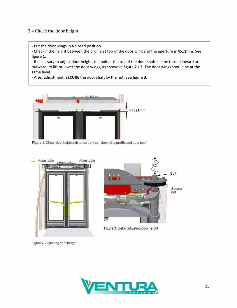
3.4 Check the door height
- Put the door wings in a closed position. - Check if the height between the profile at top of the door wing and the aperture is 45±1mm. See figure 1. - If necessary to adjust door height, the bolt at the top of the door shaft can be turned inward or outward, to lift or lower the door wings, as shown in figure 2 / 3. The door wings should be at the same level. - After adjustment, SECURE the door shaft by the nut. See figure 3.

16
3.5 Adjusting the open position of the door wings
- Put the door wings in a fully open position and check if the door wings in open position are in a 90°
angle with the step edge of the vehicle (with the nominal adjustments as done by the initial installation). Do not force the door when opening. See figure 1. - If necessary, loosen the bolts of the guiding bracket, so the guiding bracket is free to move in the upper profile of the door. See figure 2. - In a fully open position should the door stop on the door wing should touch the lower lever of the door shaft, see figure 3. If this is not possible than the cylinder should be re-adjust. See figure 2. - When necessary to adjust the fork joint of the cylinder (so the door stop contacts the lever of the door shaft) secure the fork joint afterwards, see step “link the fork joint of the cylinder”. - Put the door wing in a closed position, the guiding bracket should move frictionless through the guiding rail. Adjust the guiding bracket on behalf of this state. Push the roller on the guiding bracket softly against the inner face of the guiding rail. See figure 4.

17
3.6 Adjustment of the sliding plate
- Loosen the bolts in the sliding plate in such a way that there is still some friction when moving the sliding plate. See figure 1. - Put the door wings in a fully closed position and then push the sliding plate to the backside of the flap extension. See figure 2 / 3. - Tighten the bolts again and check if the flap is down on the right moment (when the door is almost fully closed, the flap is fully down). Otherwise re-adjust, the sliding plate.

18
3.7 Adjustment of the flap height
- Put the door wings in a fully closed position. See figure 1. - If necessary to adjust the flap height, loosen the bolts of the flap and change the flap height by means of the slotted holes. See figure 2. - The margin between the rubber flap and the step edge should be within 0.5 - 1mm. - Check if the flap runs free from the step edge during open and closing movement. See figure 2. - After adjustment, tighten the bolts, according appendix 4 “Torque setting”.


