36
Quick reference guide
| Date post: | 17-May-2018 |
| Category: |
Documents |
| Upload: | vuonghuong |
| View: | 214 times |
| Download: | 1 times |

Quick reference guide

0051
Manufactured by:Esaote S.p.A.Via di Caciolle, 15, 50127 Florence, Italy Tel. +39 055 4229 1, Fax +39 055 4229 208 Internet: www.esaote.comEmail: [email protected]

Introduction
This Quick Guide describes only the basic operating procedures to use the MyLabAlpha model, named in the following chapters as MyLab.
The precautions and detailed operating procedures as well as the installation procedures are described in the operator’s manuals (Getting Started, Safety and Standards, Probes and Consumables and Advanced Operations) provided with the system.
Carefully read the operator’s manuals provided with the system before operating with the system.
In this manual system the Control panel keys are indicated by BLUE CAPITAL LETTERS. Multifunction keys (for example LINE UPDATE) are indicated with the mention of one of the functions only (for example LINE in this example).
The enter and context menu keys are respectively indicated as ENTER and UNDO keys in this manual.
In this operation guide a WARNING pertains to possible injury to a patient and/or the operator.
A CAUTION describes the precautions which are neces-sary to protect the equipment.
Carefully read and understand all the warnings and cautions in the man-uals before operating with the system.
The user should observe each of the cautions and warnings.
Quick reference guide
WARNING
CAUTION

Index
General Information
1. Touchscreen Exam Panel Layout Multipurpose Panel Layout Alphanumeric Keyboard Layout
2. eKnob
3. eTouch Configuration Menu Customized Touchscreen Configuration Association to Real Time Preset
4. Starting an Exam
5. Ending an Exam
Image Optimization 6. Tips in B-Mode Tips to Optimize Superficial Imaging Tips to Optimize Deep Imaging Tips to Optimize Spatial Resolution Tips to Optimize Contrast Resolution Tips to Optimize Temporal Resolution
7. Tips in M-Mode Tips to Optimize Contrast Resolution
8. Tips in Color Flow Mapping (CFM) Tips to Optimize Fast Flows Tips to Optimize Slow Flows Tips to Optimize Deep Flows
9. Tips in Doppler Tips to Optimize Fast Flows Tips to Optimize Slow Flows Tips to Optimize Deep Flows
Measurements, Worksheet and Report10. Measurements How to Take Measurements
11. MyLab Worksheet
12. MyLab Report
MyLab Archive

Gen
eral
In
form
atio
n
GeneralInformation

TouchscreenThe touchscreen works in different modalities:
• as Exam panel, providing control keys to perform the exam.
• as Multipurpose panel, providing software buttons to use advanced exam controls.
• as Alphanumeric keyboard to enter data.
The touchscreen layout depends on the working modality.
Exam Panel Layout
The touchscreen is organized in three main areas, as shown in the figure below

Gen
eral
In
form
atio
n
Area FunctionGuide Graphical Convention
Scrolling Button
Navigation Area
Navigation tabs to select the desired features for the relevant controls
BROWN CAPITAL LETTERS
-
Exam Management
Buttons for the exam management (to start the exam, to change the probe or the preset…)
GREY CAPITAL LETTERS ADV>>/BASIC<<
Image Parameters Area
Control and functions to perform the exam
BLACK CAPITAL LETTERS ADV>>/BASIC<<
Buttons
Image Parameters Area – Layout
The buttons have different colors depending on the active status:
Disabled Button Active ButtonSelected/Pressed
Button
Dark gray Dark blue Light blue
Button with sub-menus
Touchscreen buttons showing a frame have a dedicated sub-menu: press the button to display the sub-menu allowing to optimize the function.

Toggles
On the bottom of the touchscreen there are six levers (or toggles) which act on the functions displayed just above.
Each lever can control two functions which depend on the active modality. The lever acts on the active control, displayed in the upper position.
To switch to the other displayed function press the corresponding button on the touchscreen: the lever will act now on the other control.
Gen
eral
In
form
atio
n
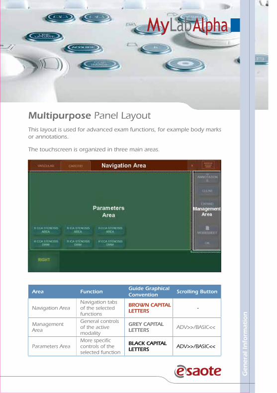
Multipurpose Panel LayoutThis layout is used for advanced exam functions, for example body marks or annotations.
The touchscreen is organized in three main areas.
Area FunctionGuide Graphical Convention
Scrolling Button
Navigation AreaNavigation tabs of the selected functions
BROWN CAPITAL LETTERS -
Management Area
General controls of the active modality
GREY CAPITAL LETTERS ADV>>/BASIC<<
Parameters AreaMore specific controls of the selected function
BLACK CAPITAL LETTERS ADV>>/BASIC<<
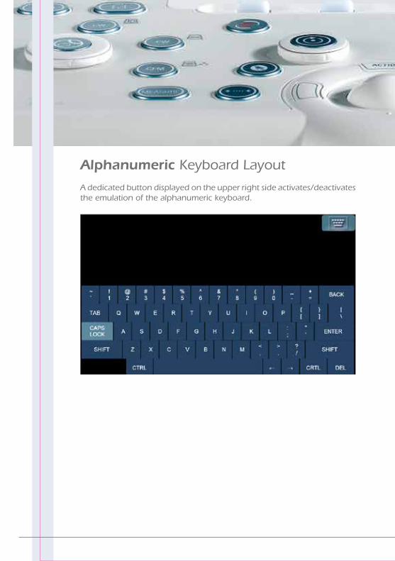
Alphanumeric Keyboard Layout
A dedicated button displayed on the upper right side activates/deactivates the emulation of the alphanumeric keyboard.

Gen
eral
In
form
atio
n
eKnobEach toggle can be associated to the EKNOB key of the control panel: in this case the knob around this key acts as the associated toggle on the active function.
The EKNOB key can be associated to more touchscreen buttons: to change the associated toggle press the EKNOB key.
eTouchThe ETOUCH key allows to record sequences of keys both of the touchscreen and of the control panel. Each recorded sequence (Macro) can be named and saved to be available as a customized button in customized touchscreens.
This key switches between factory and customized touchscreen. Whenever the customized button will be pressed, MyLab will automatically launch the keys sequence.
Once the Customized touchscreen has been configured, it has to be associated to a real time preset.
This symbol is displayed in bright orange on the touchscreen button that is correlated to the EKNOB key.
This symbol is displayed in grey on the touchscreen button that can be correlated to the EKNOB key.

Configuration MenuThe “eTouch” option of the MENU key activates the configuration menu that is organized in two main areas:
• On the left side the list of all saved customized touchscreens.
• On the right side the eTouch configuration menu, shown in the figure below.
The menu shows:
• in the center the touchscreen layout.
• on the right the menu to record the macro and to edit the customized buttons.
• on the bottom the fields where customized touchscreens are named and described.

Gen
eral
In
form
atio
n
Customized Touchscreen ConfigurationProcedure
• Press the MENU key and select the “eTouch” option.
• Select one the customized touchscreens displayed on the left side of the screen and press EDIT to modify it or CLONE to duplicate it.
• If necessary, place the cursor in the NAME field and enter the desired name and description (NOTES field).
• Place the cursor on the RECORDING field and press START to begin the recording: MyLab switches to the frozen status.
• On the upper left side of the screen is displayed the following flashing message:
Press eTouch to start recording
• Prepare MyLab to be ready for the recording so that only the keys to be used can be pressed.
• Press the ETOUCH key to start.
• Press the desired keys in sequence and press ETOUCH to end the recording.
• Place the cursor on the customized button and press ENTER to change its name.
Repeat the procedure to add other customized buttons.
Press SAVE to save the customized touchscreen.

Association to Real Time PresetProcedure
• Press the MENU key and select the “RT PRESET” option.
• Select the probe, the application and then the customized presets (displayed on the left side of the screen) and press EDIT to modify it or CLONE to duplicate it.
• If necessary, place the cursor in the NAME field and enter the desired name and description (NOTES field).
• In the “eTouch” field select the desired customized touchscreen.
• Press SAVE to save the configuration.

Gen
eral
In
form
atio
n
Starting an ExamTouchscreen
Main Display
1 2 3
5
4
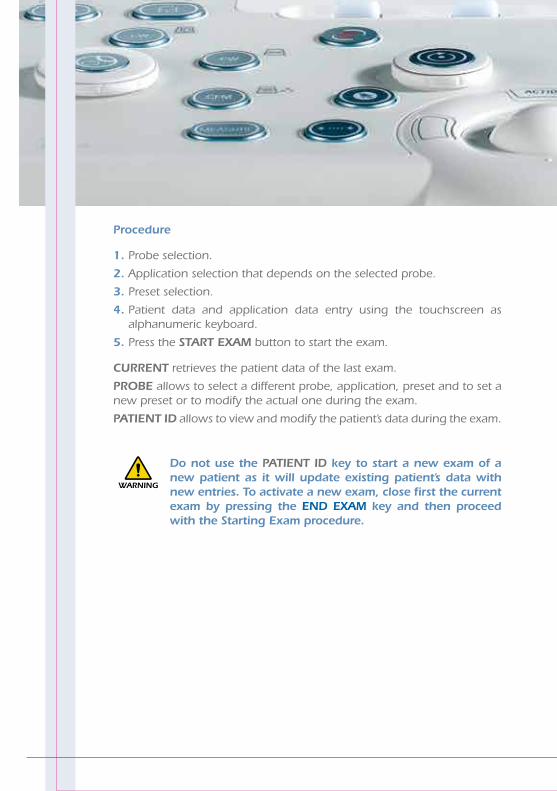
Procedure
1. Probe selection.
2. Application selection that depends on the selected probe.
3. Preset selection.
4. Patient data and application data entry using the touchscreen as alphanumeric keyboard.
5. Press the START EXAM button to start the exam.
CURRENT retrieves the patient data of the last exam.
PROBE allows to select a different probe, application, preset and to set a new preset or to modify the actual one during the exam.
PATIENT ID allows to view and modify the patient’s data during the exam.
Do not use the PATIENT ID key to start a new exam of a new patient as it will update existing patient’s data with new entries. To activate a new exam, close first the current exam by pressing the END EXAM key and then proceed with the Starting Exam procedure.
WARNING

Gen
eral
In
form
atio
n
Ending an ExamTo end the exam, press the END EXAM key: the system displays the end exam window.

The operator is enabled to simultaneously save the exam on different supports in different formats.
Field Format Destination Support
Local Archive Native format - Internal Database
Native Native format
- CD (R and RW)- DVD (+R, -R, single layer)- USB Memory Drive- Network
MultimediaSingle frame: BMP, PNG, JPEG
Clip: AVI
- CD (R and RW)- DVD (+R, -R, single layer)- USB Memory Drive- Network
DICOM DICOM
- CD (R and RW)- DVD (+R, -R, single layer)- USB Memory Drive- Network- DICOM Storage Server
If no option is selected, all data will be deleted.

Imag
e O
pti
miz
atio
n
ImageOptimization

Tips in B-Mode
Tips to Optimize Superficial Imaging
Command Function Action
FUNDAMENT/TEI Probe transmission frequency Select RES option
ZOOM Magnification of the region of interest
Enlarge the area as much as possible
FOCUSES # Number of transmission focuses Increase the focuses
FOCUS POS Focus position Move the focuses to the desired area
MVIEW (with Linear and Convex probes)
Acquisition of several bidimensional images with different steering angles
Increase to visualize organ borders and structured margins (curved or irregular borders)
Command Function Action
FUNDAMENT/TEI Probe transmission frequency Select PEN option
FOCUS POS Focus position Move the focus to the desired area
TGC Potentiometers
Amplification of individual areas of the sector
Move to right the lower TGC cursor
IMAGING GAINAmplification of overall received echo signals (General gain)
Turn clockwise for visualize deep structures
POWER Transmission power Increase the power
Tips to Optimize Deep Imaging

Imag
e O
pti
miz
atio
n
Command Function Action
FUNDAMENT/TEI Probe transmission frequencyLow frequency for penetrationHigh frequency for resolution
MVIEW (with Linear and Convex probes)
Acquisition of several bidimensional images with different steering angles
Increase to visualize organ borders and structured margins (curved or irregular borders)
FOCUSES # Number of transmission focuses
Increase the focus points as much as possible
DENSITY (with Linear and Convex probes)
Number of acquired line Increase the density as much as possible
ENHANCAmplification of the difference among adjacent structures
Increase the enhancement as much as possible
Tips to Optimize Spatial Resolution
MView may generate artifacts on the sector sides, particularly when scanning cavities. Place the area under exam in the middle of the scanning area.WARNING
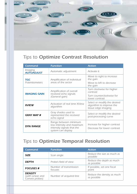
Tips to Optimize Temporal Resolution
Command Function Action
SIZE Scan angle Reduce the size as much as possible
DEPTH Probe’s field of view Reduce the depth as much as possible
FOCUSES # Number of transmission focuses
If possible, set one focal point
DENSITY (with Linear and Convex probes)
Number of acquired line Reduce the density as much as possible
Command Function Action
Imaging AUTOADJUST Automatic adjustment Activate it
TGC Potentiometers
Amplification of individual areas of the sector
Move to right to increase the gainMove to left to decrease the gain
IMAGING GAINAmplification of overall received echo signals (General gain)
Turn clockwise for higher contrastTurn counterclockwise for lower contrast
XVIEW Activation of real time XView algorithm
Select or modify the desired algorithm to improve the tissue edge imaging
GRAY MAP #Gray shades used to represented the received echo signal
Select or modify the desired post-processing curve
DYN RANGE
Range between minimum low intensity and maximum intensity signals that the system can display
Increase for higher contrastDecrease for lower contrast
Tips to Optimize Contrast Resolution

Imag
e O
pti
miz
atio
n
Tips in M-Mode
Tips to Optimize Contrast Resolution
Command Function Action
TGC Potentiometers
Amplification of individual areas of the sector
Move to right to increase the gainMove to left to decrease the gain
IMAGING GAINAmplification of overall received echo signals (General gain)
Turn clockwise for higher contrastTurn counterclockwise for lower contrast
GRAY MAP #Gray shades used to represented the received echo signal
Select or modify the desired post-processing curve
DYN RANGE
Range between minimum low intensity and maximum intensity signals that the system can display
Increase for higher contrastDecrease for lower contrast

Tips in Color Flow Mapping (CFM)
Tips to Optimize Fast Flows
Command Function Action
CFM-STEER Doppler orientation Adjust the CFM box orientation to optimize cosΘ
SCALE Pulse Repetition Frequency Increase the PRF as much as possible
FREQUENCY Probe transmission frequency Decrease the frequency as much as possible
DOPPLER GAINAmplification of overall received echo signals (General gain)
Adjust it to the reduce the noise
ACTION Cursor selector Adjust the CFM box as small as possible
Command Function Action
CFM-STEER Doppler orientation Adjust the CFM box orientation to optimize cosΘ
SCALE Pulse Repetition Frequency Increase the PRF as much as possible
FREQUENCY Probe transmission frequency Increase the frequency as much as possible
DOPPLER GAINAmplification of overall received echo signals (General gain)
Increase it as much as possible for color filling
FILTER Wall filter Reduce the filter as much as possible
Tips to Optimize Slow Flows

Imag
e O
pti
miz
atio
n
Command Function Action
CFM-STEER Doppler orientation Adjust the CFM box orientation to optimize cosΘ
SCALE Pulse Repetition Frequency Decrease the PRF as much as possible
FREQUENCY Probe transmission frequency Decrease the frequency as much as possible
DOPPLER GAINAmplification of overall received echo signals (General gain)
Increase it as much as possible for color filling
FILTER Wall filter Reduce the filter as much as possible
Tips to Optimize Deep Flows
When the CFM-STEER is set to the maximum step, some artifacts might occur showing color dots. In this case, reduce the steering by one step.WARNING
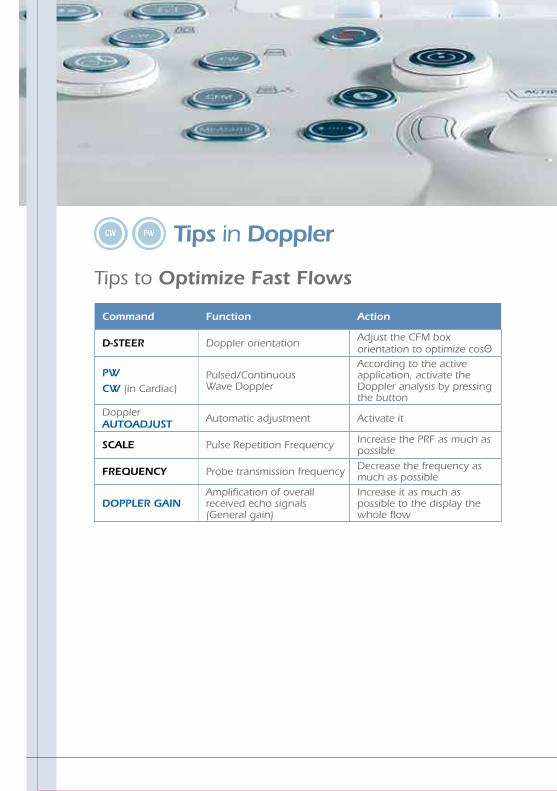
Tips in Doppler
Tips to Optimize Fast Flows
Command Function Action
D-STEER Doppler orientation Adjust the CFM box orientation to optimize cosΘ
PW
CW (in Cardiac)Pulsed/Continuous Wave Doppler
According to the active application, activate the Doppler analysis by pressing the button
Doppler AUTOADJUST Automatic adjustment Activate it
SCALE Pulse Repetition Frequency Increase the PRF as much as possible
FREQUENCY Probe transmission frequency Decrease the frequency as much as possible
DOPPLER GAINAmplification of overall received echo signals (General gain)
Increase it as much as possible to the display the whole flow

Imag
e O
pti
miz
atio
nCommand Function Action
D-STEER Doppler orientation Adjust the CFM box orientation to optimize cosΘ
Doppler AUTOADJUST Automatic adjustment Activate it
SCALE Pulse Repetition Frequency Decrease the PRF as much as possible
FREQUENCY Probe transmission frequency Increase the frequency as much as possible
BASELINE Baseline Move the baseline to eliminate the aliasing
FILTER Wall filter Reduce the filter as much as possible
Command Function Action
D-STEER Doppler orientation Adjust the CFM box orientation to optimize cosΘ
Doppler AUTOADJUST Automatic adjustment Activate it
SCALE Pulse Repetition Frequency Decrease the PRF as much as possible
FREQUENCY Probe transmission frequency Increase the frequency as much as possible
BASELINE Baseline Move the baseline to eliminate the aliasing
FILTER Wall filter Reduce the filter as much as possible
Tips to Optimize Slow Flows
Tips to Optimize Deep Flows
My Notes

Mea
sure
men
ts,
Work
shee
t an
d R
eport
Measurements,Worksheet andReport

MeasurementsMeasurements can be taken on frozen, stored and archived images.
Generic Measurements
Either the +…+ panel key or the +…+ touchscreen button activate the generic measurements menu. The touchscreen displays the list of available measurements, which are automatically identified according to the active mode, application and preset.
Advanced Calculations
Either the MEASURE panel key or the MEASURE touchscreen button activates the advanced calculations menu. The touchscreen displays the list of available measurements, which are automatically identified according to the active mode, application and preset.
Advanced measurements are organized in groups which correspond to specific anatomic structures. When a group is selected, the corresponding tab is displayed on the Navigation area and the measure is automatically started. The touchscreen displays the available measures of the selected group.
MyLab generic measurements and advanced calculations package are fully configurable.
How to Take Measurements
Both for generic and advanced measurements, the touchscreen displays the list of available measurements: select the desired measurement by pressing the corresponding button. Follow the instructions on the screen, position the cursors with the trackball and confirm the position by pressing ENTER.
The value being measured is displayed on the left of the image.
The measurements taken are marked with the √ symbol in the touchscreen.

Mea
sure
men
ts,
Work
shee
t an
d R
eport
CLEAR cancels all measurements from the screen.
UNDO key closes the session, erasing all done measurements.
ADD TO RP adds the generic measurement to the exam worksheet and report.
MyLab WorksheetWORKSHEET button can be pressed at any time to display all performed measurements.

The worksheet is organized in pages, one page for each application indicated by the corresponding tab. Each application page is then organized in sub-folders, corresponding to the measured modes and groups, identified by corresponding sub-tabs.
Touchscreen buttons allow to navigate the worksheet.
The lateral scrolling bar can be used to scroll all performed measurements in the selected mode or group.
Deleting measurements
To delete single measurements or measurements groups, place the cursor on the cross displayed beside the single measurement a/o group and press ENTER to confirm.
MyLab ReportREPORT button can be pressed at any time to display the report print preview containing the patient data and all measurements performed during the exam.
If the system is configured with a PC printer, use the printer key to print the report.

MyL
ab A
rch
ive
MyLab Archive

MyLab ArchiveARCHIVE key accesses to internal MyLab archive.
Archived exams are listed in alphabetic order. The folder symbol, when shown on the archived exams list, indicates that the corresponding exam contained images/clips.
The thumbnail of the selected exam is displayed on the right side of the screen: when more exams are selected, the thumbnail corresponds to the last selected exam.
OPEN automatically displays the selected exam(s). When more exams have been selected, the tabs displayed above the thumbnails columns allows to browse the data of the reviewed exams.
To display a thumbnail full screen, place the cursor on the desired thumbnail and press ENTER.

MyL
ab A
rch
ive
My Notes

ESAOTE S.p.A. International ActivitiesVia di Caciolle, 15 50127 Florence, ITALY Phone +39 055 42291 - Fax +39 055 4229 208
[email protected] - www.esaote.com
1410
1400
0 (M
A Re
v. 0
1)


