Pub. No. J33029EN 2013-12-01 Quick Solutions Packet VITROS ® 5,1 FS Chemistry System Topic No. Title 1 SBB-005: Quality Check Failed for Cuvette Position 2 Replacing the Slide Supply Load Door Spring 3 Communicating with the Host Computer 4 Cleaning the Plunger Sensors 5 Replacing Sensors on the Registration Rail 6 VersaTip™ Distribution Error TT4-304: No Tip Delivered to VersaTip™ Ring Load Position
Transcript
Pub. No. J33029EN2013-12-01
Quick Solutions PacketVITROS® 5,1 FS Chemistry System
Topic No. Title1 SBB-005: Quality Check Failed for Cuvette Position
2 Replacing the Slide Supply Load Door Spring
3 Communicating with the Host Computer
4 Cleaning the Plunger Sensors
5 Replacing Sensors on the Registration Rail
6 VersaTip™ Distribution Error TT4-304: No Tip Delivered to VersaTip™ Ring Load Position
jpater1
Rectangle
SBB-005: Quality Check Failed for Cuvette Position
VITROS 5,1 FS QUICK SOLUTION NO. 1
Page 1 of 4 VITROS® is a trademark of Ortho Clinical Diagnostics Inc.
This document is a troubleshooting aid only. Refer to the appropriate VITROS® 5,1 FS user documentation for more information.
2013-12-01 J33029EN
WHEN TO DO: Condition codes indicate that the Cuvettes are dirty or scratched. REQUIRED SUPPLIES: None ESTIMATED TIME: 30 minutes
1. Check the package on your newest lot of Cuvettes. If either one or both of the circled items on the lot label is different from your last lot, go to step 8.
2. Open the Right Top Cover of the
analyzer.
3. Manually loosen the 2 knurled screws for the Cuvette Shield.
4. Pull the Cuvette Shield towards the front of the analyzer and remove it.
Cuvette Shield
jpater1
Stamp
jpater1
Rectangle
SBB-005: Quality Check Failed for Cuvette Position
VITROS 5,1 FS QUICK SOLUTION NO. 1
Page 2 of 4 VITROS® is a trademark of Ortho Clinical Diagnostics Inc.
This document is a troubleshooting aid only. Refer to the appropriate VITROS® 5,1 FS user documentation for more information.
2013-12-01 J33029EN
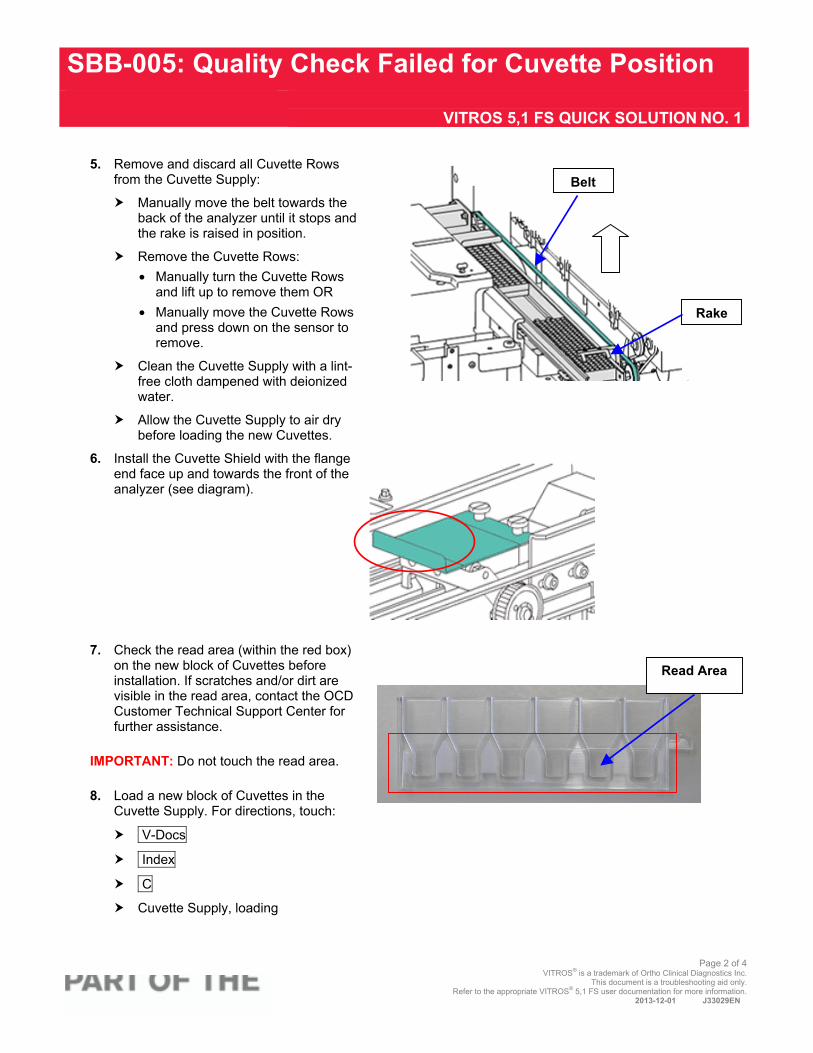
5. Remove and discard all Cuvette Rows
from the Cuvette Supply:
Manually move the belt towards the back of the analyzer until it stops and the rake is raised in position.
Remove the Cuvette Rows: • Manually turn the Cuvette Rows
and lift up to remove them OR • Manually move the Cuvette Rows
and press down on the sensor to remove.
Clean the Cuvette Supply with a lint-free cloth dampened with deionized water.
Allow the Cuvette Supply to air dry before loading the new Cuvettes.
6. Install the Cuvette Shield with the flange end face up and towards the front of the analyzer (see diagram).
7. Check the read area (within the red box) on the new block of Cuvettes before installation. If scratches and/or dirt are visible in the read area, contact the OCD Customer Technical Support Center for further assistance.
IMPORTANT: Do not touch the read area. 8. Load a new block of Cuvettes in the
Cuvette Supply. For directions, touch:
V-Docs
Index
C
Cuvette Supply, loading
.
Belt
Rake
Read Area
jpater1
Stamp
jpater1
Rectangle
SBB-005: Quality Check Failed for Cuvette Position
VITROS 5,1 FS QUICK SOLUTION NO. 1
Page 3 of 4 VITROS® is a trademark of Ortho Clinical Diagnostics Inc.
This document is a troubleshooting aid only. Refer to the appropriate VITROS® 5,1 FS user documentation for more information.
2013-12-01 J33029EN
9. Close the Top Right Cover of the
analyzer.
10. Touch Conditions and Initialize.
11. Perform the Water Blank Test:
Check that a Diluent Pack 3 is loaded in Supply 3.
Touch: • Diagnostics • Periodic Maintenance • As Required • Run Water Blank
12. If the Water Blank fails or the condition
code remains, contact the OCD Customer Technical Support Center.
Supplemental user maintenance instructions for trained operators only. For more information, contact the OCD Customer Technical Support Center.
jpater1
Stamp
jpater1
Rectangle
SBB-005: Quality Check Failed for Cuvette Position
VITROS 5,1 FS QUICK SOLUTION NO. 1
Page 4 of 4 VITROS® is a trademark of Ortho Clinical Diagnostics Inc.
This document is a troubleshooting aid only. Refer to the appropriate VITROS® 5,1 FS user documentation for more information.
2013-12-01 J33029EN
jpater1
Stamp
jpater1
Rectangle
Replacing the Slide Supply Load Door Spring
VITROS 5,1 FS QUICK SOLUTION NO. 2
Page 1 of 2
VITROS® is a trademark of Ortho Clinical Diagnostics Inc. This document is a troubleshooting aid only.
Refer to the appropriate VITROS® 5,1 FS user documentation for more information. 2013-12-01 J33029EN
WHEN TO DO: The Slide Supply Load Door Spring J27660 no longer functions, or as directed by condition
codes or Customer Technical Support. TOOLS: New Load Door Spring (J27660), needle-nose pliers, T20 TORX screwdriver
NOTE: Order two Load Door Springs (J27660) ESTIMATED TIME: IMPORTANT:
20 minutes Wait until assay processing completes before you perform this procedure.
Caution: Be sure to wear safety glasses to perform this procedure. 1. Open the top-left cover.
2. Remove the 2 screws from the Slide
Supply Load Door Hinge with a T20 TORX screwdriver. Set the screws aside to use for installation.
3. Remove the Slide Supply Load Door and place on a flat work surface.
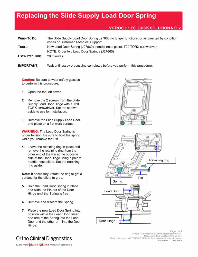
WARNING: The Load Door Spring is under tension. Be sure to hold the spring while you remove the Pin.
4. Leave the retaining ring in place and remove the retaining ring from the other end of the Pin at the opposite side of the Door Hinge using a pair of needle-nose pliers. Set the retaining ring aside.
Note: If necessary, rotate the ring to get a surface for the pliers to grab. 5. Hold the Load Door Spring in place
and slide the Pin out of the Door Hinge until the Spring is free.
6. Remove and discard the Spring.
7. Place the new Load Door Spring into position within the Load Door. Insert one arm of the Spring into the Load Door and the other arm into the DoorHinge.
Retaining ring
Pin
Door Hinge
Spring
Load Door
jpater1
Rectangle
Replacing the Slide Supply Load Door Spring
VITROS 5,1 FS QUICK SOLUTION NO. 2
Page 2 of 2
VITROS® is a trademark of Ortho Clinical Diagnostics Inc. This document is a troubleshooting aid only.
Refer to the appropriate VITROS® 5,1 FS user documentation for more information. 2013-12-01 J33029EN
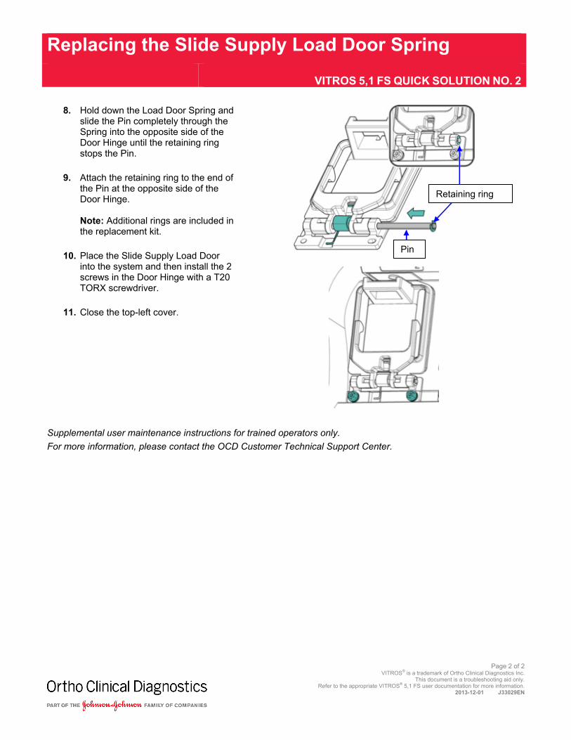
8. Hold down the Load Door Spring and
slide the Pin completely through the Spring into the opposite side of the Door Hinge until the retaining ring stops the Pin.
9. Attach the retaining ring to the end of the Pin at the opposite side of the Door Hinge. Note: Additional rings are included in the replacement kit.
10. Place the Slide Supply Load Door into the system and then install the 2 screws in the Door Hinge with a T20 TORX screwdriver.
11. Close the top-left cover.
Retaining ring
Pin
Supplemental user maintenance instructions for trained operators only. For more information, please contact the OCD Customer Technical Support Center.
jpater1
Rectangle
jpater1
Rectangle
Communicating With The Host Computer
VITROS 5,1 FS QUICK SOLUTION NO. 3
Page 1 of 6 VITROS® is a trademark of Ortho Clinical Diagnostics Inc.
This document is a troubleshooting aid only. Refer to the appropriate VITROS® 5,1 FS user documentation for more information.
2013-12-01 J33029EN
WHEN TO DO: Condition Codes indicate that requests are not downloading to the analyzer and/or results
are not uploading to the host computer. REQUIRED SUPPLIES: Loopback Test Tool ESTIMATED TIME: 15 minutes
1. Disconnect and then reconnect the LIS Cable at the back of the analyzer and, if possible, at the back of the host computer.
2. Check the port voltages:
Touch:
• Diagnostics
• System Information
• LIS Log
• Start Logging
• Log Serial Port
Note: Six values should appear, beginning with 4 values preceded by “+” and 2 values preceded by “+” or “-".
If DTR, RTS, cts, and dsr are not preceded by “+,” check that the LIS cable is connected to the back of the analyzer. If it is, contact your IT Department and suggest that either the cable is not functioning or the LIS is not communicating.
jpater1
Stamp
jpater1
Rectangle
Communicating With The Host Computer
VITROS 5,1 FS QUICK SOLUTION NO. 3
Page 2 of 6 VITROS® is a trademark of Ortho Clinical Diagnostics Inc.
This document is a troubleshooting aid only. Refer to the appropriate VITROS® 5,1 FS user documentation for more information.
2013-12-01 J33029EN
3. Check the configuration of the LIS:
Touch:
• Options
• Configure Communication
• Configure LIS
• LIS Protocol: ASTM 4. Verify the settings are appropriate and
consistent with LIS vendor protocol.
5. Check the Report Control Configuration:
Touch:
• Options
• Configure Report Control
Verify that the Transmit/Receive checkbox is checked.
Touch Save .
Test the communication again. Touch:
• Diagnostics
• System Information
• LIS Log
• Start logging
Note: You should observe the hospital LIS record across the screen.
If the problem continues, go to step 6.
jpater1
Stamp
jpater1
Rectangle
Communicating With The Host Computer
VITROS 5,1 FS QUICK SOLUTION NO. 3
Page 3 of 6 VITROS® is a trademark of Ortho Clinical Diagnostics Inc.
This document is a troubleshooting aid only. Refer to the appropriate VITROS® 5,1 FS user documentation for more information.
2013-12-01 J33029EN
6. Shut down the analyzer and, if possible, the host computer.
7. Restart the system. If there is no communication, go to step 8.
8. Test the LIS port of the analyzer with the Loopback Test Tool from your accessory kit.
Disconnect the LIS cable in the back of the analyzer and connect the Loopback Test Tool (Part No. 340031) to the LIS port.
From the analyzer screen touch:
• Diagnostics
• System Information
• LIS Log
• Start Logging
• Log Serial Port
Check for a “+” in front of DTR, RTS, cts and dsr.
Note: The ri and cd polarities are not significant for this test; however, a value should appear in front of both ri and cd. If the polarities do not appear, a problem exists with the serial cable in the analyzer or with the Master Computer Serial Port. Contact the OCD Customer Technical Support Center. If results are waiting to upload, there should be activity on the screen.
Loopback Test Tool
jpater1
Stamp
jpater1
Rectangle
Communicating With The Host Computer
VITROS 5,1 FS QUICK SOLUTION NO. 3
Page 4 of 6 VITROS® is a trademark of Ortho Clinical Diagnostics Inc.
This document is a troubleshooting aid only. Refer to the appropriate VITROS® 5,1 FS user documentation for more information.
2013-12-01 J33029EN
9. Perform a communication data capture:
Touch:
• Diagnostics
• System Information
• LIS Log
• Start Logging
• Log Serial Port
Download requests from the host computer to the analyzer.
After approximately 2 minutes, touch:
• Stop Logging
• Print Log
If the system is e-connected, start e-Connectivity. Press: Start e-Connectivity.
Note: If the system is not e-connected, send a facsimile of the printed log to the OCD Customer Technical Support Center for evaluation.
10. If there is no activity on the LIS Log screen, manually resend a result.
Touch Results .
Select a result.
Touch Set Report Status.
Check that “Apply to all selected results” is selected.
To return to the LIS Log, touch Diagnostics.
jpater1
Stamp
jpater1
Rectangle
Communicating With The Host Computer
VITROS 5,1 FS QUICK SOLUTION NO. 3
Page 5 of 6 VITROS® is a trademark of Ortho Clinical Diagnostics Inc.
This document is a troubleshooting aid only. Refer to the appropriate VITROS® 5,1 FS user documentation for more information.
2013-12-01 J33029EN
Important: The analyzer attempts to start an ASTM session with an <ENQ>. The <ENQ> is “echoed” through the Loopback Tool and appears as an LIS response. This activity is evidence of a successful Loopback Test. 11. Verify the Loopback Test is
successful. The LIS log should display a list of alternating System <ENQ> messages followed by LIS <ENQ> (see diagram). If you still require assistance, contact your LIS IT support.
Supplemental user maintenance instructions for trained operators only. For more information, contact the OCD Customer Technical Support Center.
jpater1
Stamp
jpater1
Rectangle
Communicating With The Host Computer
VITROS 5,1 FS QUICK SOLUTION NO. 3
Page 6 of 6 VITROS® is a trademark of Ortho Clinical Diagnostics Inc.
This document is a troubleshooting aid only. Refer to the appropriate VITROS® 5,1 FS user documentation for more information.
Page 1 of 2 VITROS® is a trademark of Ortho Clinical Diagnostics Inc.
This document is a troubleshooting aid only. Refer to the appropriate VITROS® 5,1 FS user documentation for more information.
2013-12-01 J33029EN
WHEN TO DO: Condition codes will be displayed when dust and debris accumulates on the sensors. TOOLS: Flat-head screwdriver; cotton swab; deionized water; lint-free cloth ESTIMATED TIME: 20 minutes WARNING: Do not do this procedure on the VITROS® 5600 Integrated System.
1. To stop idle motion on the Slide Supply Rings, touch:
Diagnostics
MEDS
Slide Supplies
Reset SS1
Note: If the reset fails, proceed to step 2.
2. Use a flat-head screwdriver to remove the Back Center Panel.
3. Loosen the three (3) Thumbscrews from the Plunger Cover.
4. Lower and remove the Plunger Cover.
5. Locate the F-shaped Sensor at the bottom of each Plunger.
6. Push the Plunger up to move the Sensor into a position where it can be cleaned.
7. Clean the Sensor with a cotton-swab moistened with deionized water.
8. Dry the Sensor with a lint-free cloth.
9. Repeat this procedure for the other Plunger.
10. Install the Plunger Cover and tighten the three (3) Thumbscrews.
Note: Verify that the Motor and Sensor wires are positioned in their notches to install the Plunger Cover or the wires may be damaged.
Cutout areaCutout area
Plunger Cover
F Sensor
Supplemental user maintenance instructions for trained operators only. For more information, contact the OCD Customer Technical Support Center.
There are three different styles of Registration Rails. This procedure is appropriate for any configuration. 1. Locate the Registration Rail Sensor that you are
replacing.
2. Use a Phillips-head screwdriver to remove the two (2) Screws.
Note: If your system has the Double Tip Scoop, loosen the two (2) screws to obtain access to the Sensors. 3. Disconnect the plug on the Sensor to allow removal.
4. Install the new Sensor and the two (2) Screws, but do
not tighten the Screws completely.
Connect the plug to the new Registration Rail Sensor. Verify that the green LED is on.
Place VersaTips in the Registration Rail and observe the yellow LED on the Sensor.
Note: When a VersaTip™ is in front of the Sensor, the yellow LED is illuminated.
• If the yellow LED is illuminated, tighten the two (2) Screws.
• If the yellow LED is not illuminated, align the Sensor until the LED is completely illuminated and then tighten the two (2) Screws.
5. Check the VersaTip™ Feeder functionality:
Empty all the VersaTips from the Versatip™ Processing Center.
Initialize the Versatip™ Feeder to allow the system to refill the Versatip™ Processing Center.
Supplemental user maintenance instructions for trained operators only. For more information, contact the OCD Customer Technical Support Center.
jpater1
Rectangle
Replacing Sensors on the Registration Rail
VITROS 5,1 FS QUICK SOLUTION NO. 5
Page 2 of 2
VITROS® is a trademark of Ortho Clinical Diagnostics Inc. This document is a troubleshooting aid only.
Refer to the appropriate VITROS® 5,1 FS user documentation for more information. 2013-12-01 J33029EN
jpater1
Rectangle
VersaTip Distribution Error TT4-304: No Tip Delivered to VersaTip Ring Load Position VITROS 5,1 FS QUICK SOLUTION NO. 6
Page 1 of 4 VITROS® is a trademark of Ortho Clinical Diagnostics Inc.
This document is a troubleshooting aid only. Refer to the appropriate VITROS® 5,1 FS user documentation for more information.
2013-12-01 J33029EN
WHEN TO DO: A VersaTip fails to be detected in the VersaTip™ Ring Load position, following a Tip delivery. TOOLS: None ESTIMATED TIME: 20 minutes
1. Open the Top Right Cover.
2. Manually rotate the VersaTip™ Ring. If the ring rotates, go to step 3. If you cannot rotate it, go to step 5.
3. Locate the VersaTip™ Sensor at the VersaTip™ Ring.
Note: The Sensor contains dual LEDs (yellow above and green below) and a red sensor. 4. Observe the red VersaTip™ Sensor
as you rotate the VersaTip™ Ring until a VersaTip crosses the sensor. The top yellow LED should illuminate.
If the yellow LED illuminates, go to step 5.
If the yellow LED does not illuminate, clean the red Versatip sensor and the black receiver with a lint-free cloth and repeat step 4.
Note: If the yellow LED still does not illuminate, contact the OCD Customer Technical Support Center. IMPORTANT: Do not initialize the system. 5. Rotate the Tip Load Coupling
counterclockwise a half turn.
6. Rotate the VersaTip™ Ring counterclockwise to move the jammed tips out of the load area.
7. Remove the jammed tips from the VersaTip™ Ring.
8. Rotate the Tip Load Coupling back into place.
LEDS & VersaTip™ Sensor
VersaTip™ Ring
Tip Load Coupling
Brass Nut
jpater1
Rectangle
VersaTip Distribution Error TT4-304: No Tip Delivered to VersaTip Ring Load Position VITROS 5,1 FS QUICK SOLUTION NO. 6
Page 2 of 4 VITROS® is a trademark of Ortho Clinical Diagnostics Inc.
This document is a troubleshooting aid only. Refer to the appropriate VITROS® 5,1 FS user documentation for more information.
2013-12-01 J33029EN
If no VersaTip™ jams are found: 1. Unscrew the Brass Nut.
2. Remove the White Tubing.
3. Remove any jammed VersaTips.
4. Touch:
Diagnostics
MEDs
VersaTip Ring / Supply
5. Direct the White Tubing toward a wall or empty space.
Caution: Be sure to direct the white tubing in a safe direction since VersaTips may be ejected. 6. Touch BLOWER and START .
7. After all VersaTips are ejected, touch
STOP .
8. Replace the White Tubing and tighten the Brass Nut.
9. Check the VersaTip™ Feeder functionality:
Empty all the VersaTips from the VersaTip™ Processing Center.
Initialize the VersaTip™ Feeder to allow the system to refill the VersaTip™ Processing Center.
10. Close the Covers.
11. Return to the Main Menu. The system will initialize.
jpater1
Rectangle
VersaTip Distribution Error TT4-304: No Tip Delivered to VersaTip Ring Load Position VITROS 5,1 FS QUICK SOLUTION NO. 6
Page 3 of 4 VITROS® is a trademark of Ortho Clinical Diagnostics Inc.
This document is a troubleshooting aid only. Refer to the appropriate VITROS® 5,1 FS user documentation for more information.
2013-12-01 J33029EN
If the TT4-304 Code displays again: 1. Open the Right Front Door.
2. Follow the procedure in V-Docs to
remove VersaTips jammed in the Tubing. Touch:
V-Docs
Index
V
VersaTip Supply
Transport Tubing, clearing
3. Check for jams in the Escapement.
4. Check the blue Tubing on the left side of the Compressor to ensure it is connected properly.
5. Detach the escapement tubing from
the Metal Escapement Tube. Remove any VersaTips accumulated in the end of the delivery tubing and then reattach the tubing.
6. Change the Compressor Filter if it has not been replaced in the last 6 months. Touch:
Maintenance
As-Required Maintenance
VersaTip Loader Compressor Filter
Blue Tubing
Escapement
Metal Escapement Tube
Supplemental user maintenance instructions for trained operators only. For more information, contact the OCD Customer Technical Support Center.
jpater1
Rectangle
VersaTip Distribution Error TT4-304: No Tip Delivered to VersaTip Ring Load Position VITROS 5,1 FS QUICK SOLUTION NO. 6
Page 4 of 4 VITROS® is a trademark of Ortho Clinical Diagnostics Inc.
This document is a troubleshooting aid only. Refer to the appropriate VITROS® 5,1 FS user documentation for more information.