BOP 1KW-MG POWER SUPPLYThis guide gives a brief introduction to the BOP 1KW-MG Power supply, shows simple load connections, and allows you to ver-ify the power supply is working. The guide also shows you how to use the front panel controls to perform the most commonlyused functions.
ACCESSING MANUALS. First determine your Firmware Version (see below), then download the BOP 1KW-MG applica-ble Operator�s Manual from www.kepcopower.com/support/opmanls.htm#bop-1k. Refer to the BOP 1KW-MG Operator�s Manual for full specifications,installation considerations and operating instructions, including. an Installation/Operation Summary which includes hyperlinkedreferences to detailed procedures, but which can be printed as a handy reference.The BOP 1KW-MG Operator�s Manual alsoincludes a full description of the digital interfaces and the SCPI command language.
FIRMWARE VERSION. Refer to www.kepcopower.com/support/bophifirm.htm to determine which firmware version isinstalled.
ACCESSING DRIVERS. Drivers are accessed from www.kepcopower.com/drivers/drivers-dl3.htm.
I � DESCRIPTION.The BOP 1KW-MG Series hereafter referred to asBOP, are true 4-quadrant programmable voltage andcurrent power supplies, meaning they are capable ofboth sourcing and sinking power (see Figure 1).These bipolar power supplies pass smoothlythrough zero without switching to provide true ± volt-age and ± current. These BOP power supplies useswitch mode technology for low dissipation. A bi-directional, isolating, a-c input power factor correct-ing (PFC) circuit recuperates energy sinked from anactive load and sends it back into the line to maintainlow dissipation.
These BOP power supplies are controlled digitallyfrom a menu-driven front-panel keypad or one of thestandard remote digital interfaces (GPIB or RS 232)to set voltage and current and the four protection
limits (+voltage, �voltage, +current and �current.) Afront panel rotary adjuster allows real-time adjust-ment of the output. A large LCD displays the modeof operation, the settings, and the actual output volt-age and current. Additionally, these BOP modelscan be remotely controlled by an analog ±10V inputfor the main channel (voltage or current), and a +1 to+10V input for the limit channels.
BOP models are suitable for driving inductive loadssuch as large magnets or motors, and for exercisingbatteries. They are also suitable for characterizingsolar cell arrays, and powering many electrochemi-cal reactions.
.
II � UNPACKING.This instrument has been thoroughly inspected andtested prior to packing and is ready for operation.After careful unpacking, inspect for shipping damagebefore attempting to operate. Perform the �Prelimi-nary Operational Check.� on page 5. If any indication
of damage is found, file an immediate claim with theresponsible transport service.
III � EQUIPMENT SUPPLIED. See Table 2.
TABLE 1. BOP 1KW-MG MODEL PARAMETERS
Model
d-c Output Range Closed Loop Gain Output Impedance
Voltage(V d-c)
Current(A d-c)
Voltage ChannelGV (V/V)
Current ChannelGI (A/V)
Voltage Mode(Series R - L)
Current Mode(Parallel R - C)
Rd-c(mOhms)
L(µH)
Rd-c(Ohms)
C(µF)
1000 WATT MODELS
BOP 6-125MG 0 to ±6 0 to ±125 0.6 12.5 0.05 1.5 24 1150
BOP 10-100MG 0 to ±10 0 to ±100 1.0 10.0 0.1 2.0 50 1100
BOP 10-75MG 0 to ±10 0 to ±75 1.0 7.5 0.13 2.0 67 976
BOP 20-50MG 0 to ±20 0 to ±50 2.0 5.0 0.40 8.3 200 371
BOP 25-40MG 0 to ±25 0 to ±40 2.5 4.0 0.63 15.8 313 165
BOP 36-28MG 0 to ±36 0 to ±28 3.6 2.8 1.30 25 640 103
BOP 50-20MG 0 to ±50 0 to ±20 5.0 2.0 2.50 50 1250 55
BOP 72-14MG 0 to ±72 0 to ±14 7.2 1.4 5.14 104 2570 33
BOP 100-10MG 0 to ±100 0 to ±10 10.0 1.0 10.0 163 5000 16
NOTE: When connecting active loads, the steady-state voltage of the active load must not exceed the maximum voltage rating of the BOP. Otherwise the overvoltage protection will shut down the power supply.
TABLE 2. EQUIPMENT SUPPLIED
ITEM FUNCTION PART NUMBER
Source Power Entry mating connector Mates with source power entry connector 142-0381 (Kepco) (IEC 320)
PAR/SER CONTROL - IN mating connector
Mates with PAR/SER CONTROL - IN port to allow access to pins required for calibration
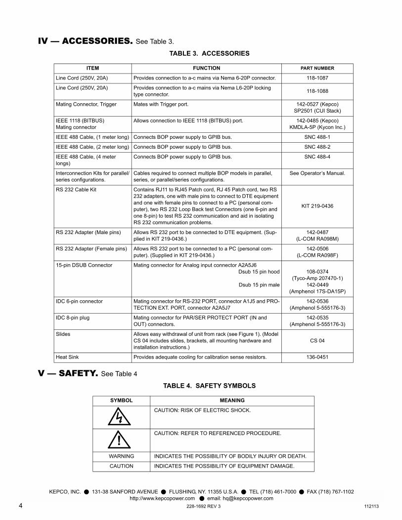
IEEE 488 Cable, (1 meter long) Connects BOP power supply to GPIB bus. SNC 488-1
IEEE 488 Cable, (2 meter long) Connects BOP power supply to GPIB bus. SNC 488-2
IEEE 488 Cable, (4 meter longs)
Connects BOP power supply to GPIB bus. SNC 488-4
Interconnection Kits for parallel/series configurations.
Cables required to connect multiple BOP models in parallel, series, or parallel/series configurations.
See Operator�s Manual.
RS 232 Cable Kit Contains RJ11 to RJ45 Patch cord, RJ 45 Patch cord, two RS 232 adapters, one with male pins to connect to DTE equipment and one with female pins to connect to a PC (personal com-puter), two RS 232 Loop Back test Connectors (one 6-pin and one 8-pin) to test RS 232 communication and aid in isolating RS 232 communication problems.
KIT 219-0436
RS 232 Adapter (Male pins) Allows RS 232 port to be connected to DTE equipment. (Sup-plied in KIT 219-0436.)
142-0487(L-COM RA098M)
RS 232 Adapter (Female pins) Allows RS 232 port to be connected to a PC (personal com-puter). (Supplied in KIT 219-0436.)
142-0506(L-COM RA098F)
15-pin DSUB Connector Mating connector for Analog input connector A2A5J6Dsub 15 pin hood
Dsub 15 pin male
108-0374 (Tyco-Amp 207470-1)
142-0449(Amphenol 17S-DA15P)
IDC 6-pin connector Mating connector for RS-232 PORT, connector A1J5 and PRO-TECTION EXT. PORT, connector A2A5J7
142-0536(Amphenol 5-555176-3)
IDC 8-pin plug Mating connector for PAR/SER PROTECT PORT (IN and OUT) connectors.
142-0535(Amphenol 5-555176-3)
Slides Allows easy withdrawal of unit from rack (see Figure 1). (Model CS 04 includes slides, brackets, all mounting hardware and installation instructions.)
CS 04
Heat Sink Provides adequate cooling for calibration sense resistors. 136-0451
TABLE 4. SAFETY SYMBOLS
SYMBOL MEANING
CAUTION: RISK OF ELECTRIC SHOCK.
CAUTION: REFER TO REFERENCED PROCEDURE.
WARNING INDICATES THE POSSIBILITY OF BODILY INJURY OR DEATH.
CAUTION INDICATES THE POSSIBILITY OF EQUIPMENT DAMAGE.
VI � PRELIMINARY OPERATIONAL CHECK.A simple operational check after unpacking andbefore equipment installation is advisable to ascer-tain whether the power supply has suffered damageresulting from shipping.
1. With POWER switch set to off position, connectthe power supply to source power (see �InputConnections.� on page 5.
2. With no load connected, set POWER switch tothe ON position. Each time the unit is turned onan internal self-test is performed. If all tests pass,the unit goes into the default mode. If a failureoccurs, the failure is displayed. Figure 5 shows
the factory-configured power on defaults dis-played on the LCD.
3. Connect a digital voltmeter (DVM) (resolution andaccuracy of 0.01% or better) to the OUT S andCOM S terminals at the rear panel terminal block.
4. Use the keypad to enter the rated maximum volt-age of the power supply (e.g., enter 36 for amodel BOP 36-28MG) and press ENTER. IfSTANDBY indicator is lit, press STANDBY key.
5. Verify DVM voltage reading agrees with pro-grammed voltage within 0.03% of rated maximumvoltage and agrees with displayed voltage onLCD within 0.05% of rated maximum voltage.
VII � INSTALLATION.Install units either on a bench or in a 19 inch-widerack. For rack mounting: remove four feet first; rackmust provide support at the rear). Optional slidesmay be used. Leave the front and rear panels clearof obstructions to ensure adequate cooling. For par-allel, series and master-slave configurations, refer tothe Operator�s Manual.
INPUT CONNECTIONS. Source power is con-nected to the power supply via three-wire inputpower using the source power mating connectorsupplied (see Table 3). This power supply operatesfrom single phase a-c mains power (or between twophases of 3-phase a-c mains power), 230V, 50/60Hznominal (range: 176 - 264V, 47-63Hz) without anyneed for range selection. The user must provide aproperly sized and rated mains lead (line cord) andservice with a current rating compatible with theanticipated input current. Line cords available asaccessories are listed in Table 3. Plug the sourcepower connector into the source power inlet connec-tor at the rear panel.
LOAD CONNECTIONS. Power connections re-quire wires that are properly rated for the nominal out-put current of the unit. Connect the load to the OUT-PUT and COMMON power terminals on the rearpanel (see Figure 3). OUT S and COM S terminal ofthe Monitor and Sensing Terminal block are for con-nection of remote sensing leads (after removing thefactory-installed local sensing links). NOTE: OutputSense lines must be connected for proper opera-tion, either locally, or at the load (remote). Alsouse OUT S and COM S to monitor voltage at theload using external equipment such as a DVM, oscil-loscope, etc. Use OUT MON and COM MON tomonitor voltage at the BOP output.
It is critical that configurations comprised of BOP,load, and external programming devices, have a sin-gle earth-ground point. Observe the following cau-tion and refer to the applicable BOP 1KW-MGOperator Manual for earth-ground recommenda-tions. Failure to observe this caution will void thewarranty!
CAUTION: Never connect both the loadterminal tied to the BOP COM terminaland the programming device commonto earth-ground. This compromisesaccuracy and will cause catastrophicdamage to the BOP if the connectionbetween BOP COM and the load termi-nal tied to earth-ground is lost.
LOCAL SENSING (FACTORY DEFAULT). Unit is shipped with local sensing links installed:OUT S connected to OUT MON and COM MONconnected to COM S (see Figure 4A).
REMOTE SENSING SELECT. First remove thefactory-installed local sensing links between OUT Sand OUT MON and between COM MON and COMS. Then connect the OUT S and COM S lines at theload (see Figure 4B) using #22 AWG wire, twistedpair. ANALOG I/O CONNECTIONS. The Analog I/OPort connector, located on the rear panel of the BOP1KW power supply (see Figure 3), provides accessto analog programming inputs which can control themode of operation (voltage or current), output volt-age or current, and establish positive and negativevoltage and current limits. An output analog corre-sponding to output current is also provided. Refer toOperator�s manual for details.
TRIGGER CONNECTIONS. The Trigger Port(see Figure 3) provides for an external trigger inputfor use with SCPI *TRG and TRIG commands. Referto Operator�s manual for details.
GPIB CONNECTIONS. Your computer musthave a GPIB interface card installed. Connect thepower supply to the computer�s GPIB interface card.Use a standard GPIB interface cable at the GPIBport on the rear panel (see Figure 3). The defaultGPIB address is 6; refer to the Operator�s Manual tochange it.
FIGURE 2. BOP 1KW SERIES, FRONT PANEL CONTROLS AND INDICATORS
RS 232 CONNECTIONS. Connect the BOP1KW to a modem using a Null Modem patch cable atthe RS 232 port located on the rear panel (See Fig-ure 3). A Null Modem cable is not required for olderMAC computers with D-sub serial port in which the
RXD and TXD line transposition is accomplished viaexternal hardware. The default baud rate is 38400;refer to the Operator Manual to change it.
FIGURE 3. BOP 1KW SERIES, REAR PANEL VIEW, LINKS INSTALLED FOR LOCAL SENSING
VIII � OPERATION.Additional features covered in the Operator Manualare: Quick Boot (eliminating the power- up displays),use of the internal relay, operation via the LAN inter-face or analog signals and setting coarse/fineadjustment preference of the VOLTAGE and CUR-RENT controls. An Installation/Operation Summaryis also included in the Operator Manual. The Opera-tor Manual also covers the GPIB and RS232interfaces, including the use of the drivers down-loadable from: www.kepcopower.com/drivers/drivers-dl3.htm#bop1k.TURNING THE POWER SUPPLY ON.
CAUTION:
DO NOT repeatedly toggle the cir-cuit breaker/switch as this maydamage the unit.
Set POWER ON/OFF circuit breaker/switch on frontpanel to ON. If actuator does not lock whenreleased, wait a few seconds before trying again.The circuit breaker is �trip-free� design; if overloadexists, contacts cannot be held closed by actuator.
� When the power supply is turned on, it per-forms a brief self-test that includes testing thethree processors (analog, interface and dis-play), then displays the power-up screen (seeFigure 5). If an error is detected, the FAULTindicator will light, information about the errorwill be briefly displayed on the LCD.
� If the unit powers up in REMOTE mode, press! to set the unit to LOCAL mode.
� If the display is not viewable, press # twice.The display will cycle through the range ofcontrast settings. Press # again to lock inthe preferred contrast.
ACCESSING THE MENUS. From the power-upscreen, pressing the Function keys indicated on theLCD opens the associated menu. The menu openedmay list submenus that may be opened eitherdirectly by pressing the associated Function keys, orby highlighting an item on the list and pressing theView/Modify function key. Menus and submenus willdisplay a list of parameters, with the top one high-lighted. The function key assignments can vary, butgenerally offer the following choices:
� ! allows the highlighted parameter to beviewed or modified. After changing the param-
eter, the following choices are available: $ -SAVE or ENTER to save the change, % -EXIT to abort the change and exit to the previ-ous menu.
� @ - RESTORE DEFAULT restores factorydefaults for the parameters displayed (exceptfor GPIB address). The factory defaults maybe saved as power-up defaults by pressing$.
� # - The function varies, depending on themenu. In most cases # is used to abort achange without applying the modified setting.From the power-up screen # is used toadjust contrast. In the Revisions/TEST sub-menu of the General Setup Menu, # is usedto execute a test.
� $ - SAVE FOR POWER-UP Saves the con-figuration shown as a power-up setting so thechanges will not be lost when the unit isturned off.
� % - APPLY EXIT applies the current(changed) setting without saving for power-upand exits to the previous menu or to thepower-up screen, EXIT leaves the currentmenu without saving or applying changes.
The menu structure is as follows (NOTE: BOLD =Factory Default):
Power-up Screen (Power up menu)� ! - Save/Recall� � Saved Setups: Recall one of 99 saved set-
ups.� � � Saved Setup Details: Mode (voltage/
current), main channel reference (inter-nal/external/external reference level)and setting, protection limit (internal/external/lesser limit) and setting(s), out-put status (on/off)
� @ - Waveform � � Saved Waveforms: Choose one of 16
saved waveforms.� � � New Waveform Settings: Name (max.
� � � � Segment Details: Type (square/±ramp/triangle/sine/level),frequency or period, p-p amplitude,offset, start/stop angle for sine andtriangle, initial/repeat
� # - Display� � Display and Beep Settings: Display
� � Calibration: Voltage, Current and Externaland Controls calibration
� � Power-up Settings: Mode (Voltage/Cur-rent), Main channel reference (Internal/External/External Reference Level), pro-tect channel type (Internal/External/LesserLimit), Voltage Protect Limit (currentmode), Current Protect Limit (voltagemode) output on/off
� � Password� � � Password Settings: Menu protection
(Interface/Max-Min/Load/Test/Power-up/Keypad @ local/Keypad@power-up), Save Display chg (Enable/Dis-able), Passwords (Main/Admin1/Admin2 or Unprotected)
� � Series/Parallel: Configuration (Standalone/Parallel/Series/Master 2X2/Master 3X2);for parallel or series: Unit Type (Stand-alone/Master+1 to+4/Slave #1 to #5) andConnection Type: shows Series or Paral-lel).
FIGURE 5. POWER-UP SCREEN SHOWING GRAPHIC METERS
HOW TO MODIFY A PARAMETER. First access the parameter by accessing the propermenu as described above. To modify a parameterlisted in a menu or submenu, proceed as follows:
1. Highlight the parameter using the Y and U keys.2. When the desired choice is highlighted, press !
to modify the active setting. The choices are dis-played with the active setting highlighted. In thecase of numerals, the units digit is highlighted. � To change a numeric setting, press the num-
ber keys, then press ENTER to program thenumbers entered. Use the CLEAR key toclear numbers entered and start over. TheADJUST control can also be used to incre-ment or decrement the highlighted digit.
Pressing ADJUST while rotating adjusts theleast significant digit. If the output is on (unitnot in Standby) changes made using theADJUST control are immediately applied tothe output.
� For alphanumeric characters use multiplepresses of the number keys for letters or sym-bols: 0 (space), 1 (+, �, /), 2 (ABC), 3(DEF), 4 (GHI), 5 (JKL), 6 (MNO). 7(PQRS), 8 (TUV), 9 (WXYZ). Use the Tkey to highlight the next character. As an alter-native, the U or Y keys or ADJUST controlwill scroll through numbers, and letters andsymbols. Use the CLEAR key to clear theentire alphanumeric field and start over
3. Press $ to apply the change and return to themenu (to change another parameter, repeat steps1 and 2). To abort (return to the menu withoutapplying the change), press %.
NOTE:Press HELP key for more information,press HELP again to see multiplescreens; press CLEAR key to exit thehelp screen.
ADJUSTING LCD BRIGHTNESS, CON-TRAST AND BACKGROUND From the power-up screen, (Figure 5), press # twice to initiate con-trast adjustment. The contrast gradually alternatesbetween light and dark. When the contrast is accept-able, press # to apply the change and exit contrastadjust. Use the T and R keys for fine adjustmentof contrast. Contrast can also be adjusted from thepower-up screen by pressing # once, then press-ing T and R as needed for fine adjustment.
To change the background, press # from thepower-up screen, Highlight Background, press !,highlight Black or White, then $ to save. Press $exit and save for power-up or % to apply thechanges (without saving for power-up) and exit.
ENABLING/DISABLING AUDIBLE BEEPS From the power-up screen, press #, then modifythe setting. Even though audible beeps are set to off,the beeps will still sound upon power-up or detectionof a power supply fault.
SETTING VOLTAGE OR CURRENT MODE The BOP uses two separate channels, one to setoutput voltage or current and one to set the corre-sponding protection limit. The main channel is deter-mined by the MODE key (in local mode) whichalternately selects either Voltage mode or Currentmode or by SCPI command (in digital remote mode).The protection channel is determined automaticallyby the main channel selected. When Voltage modeis selected, the current protection channel is active,and when Current mode is selected, the Voltageprotection channel is active.
PROGRAMMING VOLTAGE OR CURRENT AND ASSOCIATED PROTECT LIMITS Fromthe power-up screen the settable voltage/currentparameters are displayed at the bottom of the LCDabove the HELP message. Use Y or U to highlightthe main or protect channel.
1. To verify that the unit is configured for internal ref-erences press $ from the power-up screen andverify that Reference Input and Protection Limitare set to Internal, and External Mode is set toDisable. If necessary to change a setting, use Yor U to highlight the parameter, and press ! tomodify. Highlight the desired selection and press$ to save, then press $ to save for power-upor % to exit. If analog programming is desired,refer to Operator�s Manual.
2. Verify that the load has been configured properlyto ensure that the unit behaves as expected whenthe output is off (see PAR. for details).
3. Press MODE key to select the main channel(VOLTAGE or CURRENT); the associated PRO-TECT channel is automatically selected and dis-played.
4. Set the output on or off as desired using theSTANDBY key. The output is off (disabled) whenthe STANDBY indicator is lit, on (enabled) whennot lit.
5. Use Y or U to highlight the main channel. Thereare two ways to program the output in local mode.These methods can be used either when the out-put is disabled (STANDBY indicator lit) orenabled.
WARNING:
When the ADJUST control isrotated, the active parameter isimmediately effective if the outputis enabled (on = STANDBY indica-tor not lit). The voltage/currentapplied to the load changes as theADJUST control is rotated.
� Use the ADJUST control to increase ordecrease the main channel setting (e.g., volt-age when the unit is in voltage mode). Startwith the most significant digit of the desiredvalue, then use T to highlight the next digit.For fine adjustment press the ADJUST controlin while rotating the knob to modify the leastsignificant digit.
� Enter the desired value on the keypad usingthe number keys. For example, to program theBOP to 75.8V, press the following keys inorder 75.8 then press ENTER. For fineadjustment use Y, and U to modify the leastsignificant digit. To correct the entry before
activation press the CLEAR key to set thevalue to zero and start over. When the desiredvalue is displayed, press ENTER. This causesthe new value to appear at the output and beapplied to the load if the output is enabled.
6. To program the corresponding Protect channel,press Y or U as necessary to highlight the Pro-tect channel. Then set the value using either ofthe two methods described above. If the ProtectEntry setting is set to Independent, separateentries for the positive and negative protect chan-nel are possible. Otherwise the value entered isapplied to both positive and negative protectchannels.
NOTE: The BOP can be configured to showthe protection limits as either a singlevalue that applies to both protectionchannels or show individual settingsfor positive and negative protectionlimits. See Operator�s Manual fordetails
SOFTWARE LIMITS. Software limits preventprogramming of the main channel or the Protectchannel beyond the software limit value. Refer toOperator�s Manual for a full explanation of softwarelimits.Changing Main Channel Software limit. This procedure allows the user to determine themaximum value of voltage or current that can beprogrammed.
1. Press % from the power-up screen to enter theGeneral Setup menu, then highlight Max/Min Set-tings.
2. Press ! to enter the Max/Min Settings submenu(Figure 6). (If a Password is required, see Opera-tor�s Manual for instructions.)
3. Highlight the voltage or current max/min valueand press ! to change it. Software limits areabsolute values (do not use minus sign for nega-tive limits). Use number keys to change the set-ting, then $ to save.
4. When complete, press $ to save for power-up,# to abort, or % to apply the changes (withoutsaving for power-up) and exit.
5. Upon return to the power-up screen, the mainchannel (voltage or current) is compared againstthe main channel limits in effect. If the main chan-nel exceeds the limit, it is set to zero.
6. Highlight the ±CPROTECT or ±VPROTECT max/min value and press ! to change it. Softwarelimits are absolute values (do not use minus signfor negative limits). Use number keys to changethe setting. Press $ to save, or % to abort.
7. When complete, press $ to save for power-up,or # to abort, or % to apply the changes (with-out saving for power-up) and exit.
Upon return to the power-up screen, the new protec-tion limit (voltage or current) is compared against theprotection limits in effect. If the new protection limitsetting is below the existing setting for the protectionlimit, the protection channel (voltage or current) isset to zero.
DETERMINING HOW THE UNIT RESPONDS WHEN OUTPUT IS OFF (LOAD TYPE) TheBOP supports three Load Type selections (seeTable 5) which determine how the power supplyresponds when the output is off: ACTIVE, RESIS-TIVE and BATTERY. The Load Type selection does
not affect the settings of the power supply for ONstate; it only affects the main internal reference leveland the protection levels during the OFF state.
WARNING
For inductive loads, and especiallysuperconducting magnet typeloads, the inherent offset of theBOP in the OFF state may generatesignificant current in the circuit. Aproperly rated switch in parallelwith a resistor must be connectedbetween the power supply and theload. The switch must be open andthe BOP front panel LCD must read0V, 0A before removing or install-ing connections between BOP andload.
Active. Active mode (default setting) is necessaryfor the power supply to function properly and safelywith inductive loads and constant-current-type activeelectronic loads. Active mode can also be used withresistive loads. Table 5 indicates how the power sup-ply responds to a command to go from Output ON toOFF. When the output is disabled, the unit is set tovoltage mode, voltage is set to zero and both currentprotect and voltage limit are set to maximum. When
the unit is enabled, the pre-existing settings for volt-age, current protect and voltage limit are restored.
WARNING
For both inductive loads and con-stant-current-type active electronicloads when the BOP output is setto OFF, a path is provided forabsorbing either the energy accu-mulated in the reactance of theload during the ON state, or energydelivered by an electronic load.This prevents damage to the loadand power supply as well as pro-viding safety for the user. However,In addition to the built-in safety fea-tures, constant-current-type activeelectronic loads must be adjustedto zero and the BOP front panelLCD must read 0V, minimum cur-rent, before handling the powersupply-to-load connections.
TABLE 5. POWER SUPPLY BEHAVIOR WHEN OUTPUT IS SET TO OFF
LOAD TYPESETTING
If unit was in Voltage Mode when output OFF command issued.
If unit was in Current Mode when output OFF command issued.
ACTIVE
� Unit remains in voltage mode.� Voltage set to zero.� Both ± Current Protect set to maximum.� Both ± Voltage Limit remain at maximum.
� Unit set to voltage mode.� Voltage set to zero.� Both ± Current Protect remain at maximum.� Both ± Voltage Limit set to maximum.
RESISTIVE
� Unit remains in voltage mode.� Voltage set to zero.� Both ± Current Protect set to minimum box values.� Both ± Voltage Limit. remain at maximum.
� Unit remains in current mode.� Current set to zero.� Both ± Current Protect set to minimum box values.� Both ± Voltage Limit set to maximum,
BATTERY
� Unit set to current mode.� Current set to zero.� Both ± Voltage Protect. remain at maximum.� Both ± Current Limit set to maximum.
� Unit remains in current mode,� Current set to zero.� Both ± Voltage Protect set to maximum.� Both ± Current Limit remain at maximum.
Resistive. This mode, as the name suggests, isuseful for resistive loads. Table 5 indicates how thepower supply responds to a command to go fromOutput ON to OFF.
WARNING
Accessing the BOP after the outputis disabled in BATTERY mode ishazardous because (1) high currentarcing is possible and (2) either theexternal battery voltage, or the volt-age (±Voltage Protection max) onthe BOP output terminals may bedangerous. Therefore, for batteryand constant-voltage-type activeelectronic loads it is recommendedthat two properly rated externalswitches be installed for safety:one in series with the battery, andone across the BOP output. Afterthe unit is set to OFF, first open theswitch in series with the battery,then close the switch across theBOP output to ensure safety beforehandling BOP connections. Whenconnecting the battery, the switchacross the output should beopened after the connections arecomplete and then the switch inseries with the battery should beclosed. If the constant-voltage-typeactive electronic load is adjusted tozero before handling the powersupply-to-load connections, onlythe switch across the BOP outputis required.
Battery. This mode is necessary for the power sup-ply to function properly and safely with either batteryor constant-voltage-type active electronic loads.This mode prevents the battery from dischargingduring the OFF state. When the output is disabled(set to OFF), the BOP will go to current mode, cur-rent will be set to zero, with voltage protect and cur-rent limit set to maximum. In this way the battery willnot be discharged while the output is OFF. For con-stant-voltage-type active electronic loads this modestops energy flow during the OFF state. Table 5 indi-cates how the power supply responds to a commandto go from Output ON to OFF.
CONFIGURE LOAD TYPE. To configure, press% from the power-up screen, then highlight LoadType and press ! to modify. (If a Password isrequired, see Operator�s Manual for instructions.)Highlight Active, Resistive or Battery (see explana-tions and associated WARNINGS above) and press$ to save. Then press $ to save for power-up,# to abort, or % to apply the changes (withoutsaving for power-up) and exit. After configuring, thenew setting will be effective when the power supplygoes from output on to output off.
To restore factory default (Active), press % fromthe power-up screen, highlight Load Type, press!, then press @ to restore default. Press $ tosave for power-up or % to exitENABLING/DISABLING OUTPUT POWER. The BOP output can be disabled (OFF) or enabled(ON) by toggling the STANDBY key in local mode.The behavior of the unit when disabled depends onthe Load Type setting (See �Determining How theUnit Responds when Output is OFF (Load Type)� onpage 12. and Table 5 for details).
IX � ADDITIONAL FEATURES. The user is urged to refer to the Operator�s Manualfor full explanations all BOP 1KW features, includ-ing:
� Passwords - three independent levels ofaccess
� Changing the Default Power up Settings� Digital Remote Operation - using SCPI com-
mands via RS 232 or GPIB ports� Analog Remote Operation - via Analog I/O
port� Details about Protect Limits and Software-
controlled limits
� Storing/Recalling Power Supply Output Set-tings
� Waveform Generation - Sine, Triangle,±Ramp, Square and Level segments. Localoperation allows up to 16 waveforms, maxi-mum 10 segments per waveform. Remoteoperation allows 1 waveform, maximum of126 segments, or using LIST commands.
� Operator Testing� Calibration - via either local keypad or remote