14
Example SOFiSTiK AG 2008 Quick Start Guide Prestressd Slabs
| Date post: | 18-Apr-2018 |
| Category: |
Documents |
| Upload: | truongtuyen |
| View: | 244 times |
| Download: | 3 times |
Example
SOFiSTiK AG 2008
Quick Start Guide Prestressd Slabs

Example
page 1 Prestressed Slab
1 Scope Slab prestressing provides an economical way to decrease the amount of required
reinforcement (ULS) while allowing for larger spans with slender slabs and better
structural performance regarding crack and deflection control. For similar economical
graphical input and FEA analysis, SOFiSTiK software offers special features within
the Structural Desktop SSD and SOFiPLUS. In the following quick start guide the
different tasks and features will be explained briefly.
Required versions: SSD 10.64-23 or higher for analysis / SOFiPLUS(-X) 16.4/17.1-16 or higher for the graphical input.
Example
page 2 Prestressed Slab
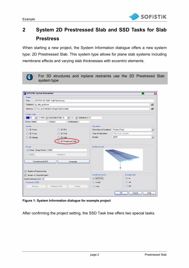
2 System 2D Prestressed Slab and SSD Tasks for Slab Prestress
When starting a new project, the System Information dialogue offers a new system
type: 2D Prestressed Slab. This system type allows for plane slab systems including
membrane effects and varying slab thicknesses with eccentric elements.
For 3D structures and inplane restraints use the 2D Prestressd Slab system type
Figure 1: System Information dialogue for example project
After confirming the project setting, the SSD Task tree offers two special tasks.
Example
page 3 Prestressed Slab
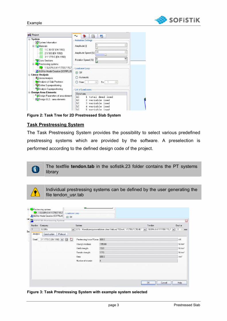
Figure 2: Task Tree for 2D Prestressed Slab System
Task Prestressing System
The Task Prestressing System provides the possibility to select various predefined
prestressing systems which are provided by the software. A preselection is
performed according to the defined design code of the project.
The textfile tendon.tab in the sofistik.23 folder contains the PT systems library
Individual prestressing systems can be defined by the user generating the file tendon_usr.tab
Figure 3: Task Prestressing System with example system selected
Example
page 4 Prestressed Slab
Example System: SUSPA/DSI® Monostrands 150 mm² acc. ETA-03/0036:
Company: SUSPA
System: ETA Monolitzenspannverfahren ohne Verbund 150mm²
Tendon: SUSPA 6-4 Y 1770 (Pack of 4 Monostrands)
Check of the prestressing force:
P0, max: with ft0.1k = 1520 N/mm² = 0.9*1520 N/mm² * 600 mm²= 820 kN
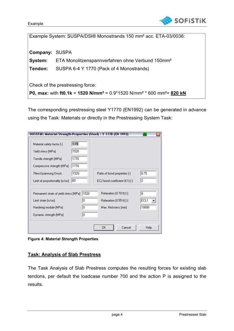
The corresponding prestressing steel Y1770 (EN1992) can be generated in advance
using the Task: Materials or directly in the Prestressing System Task:
Figure 4: Material Strength Properties
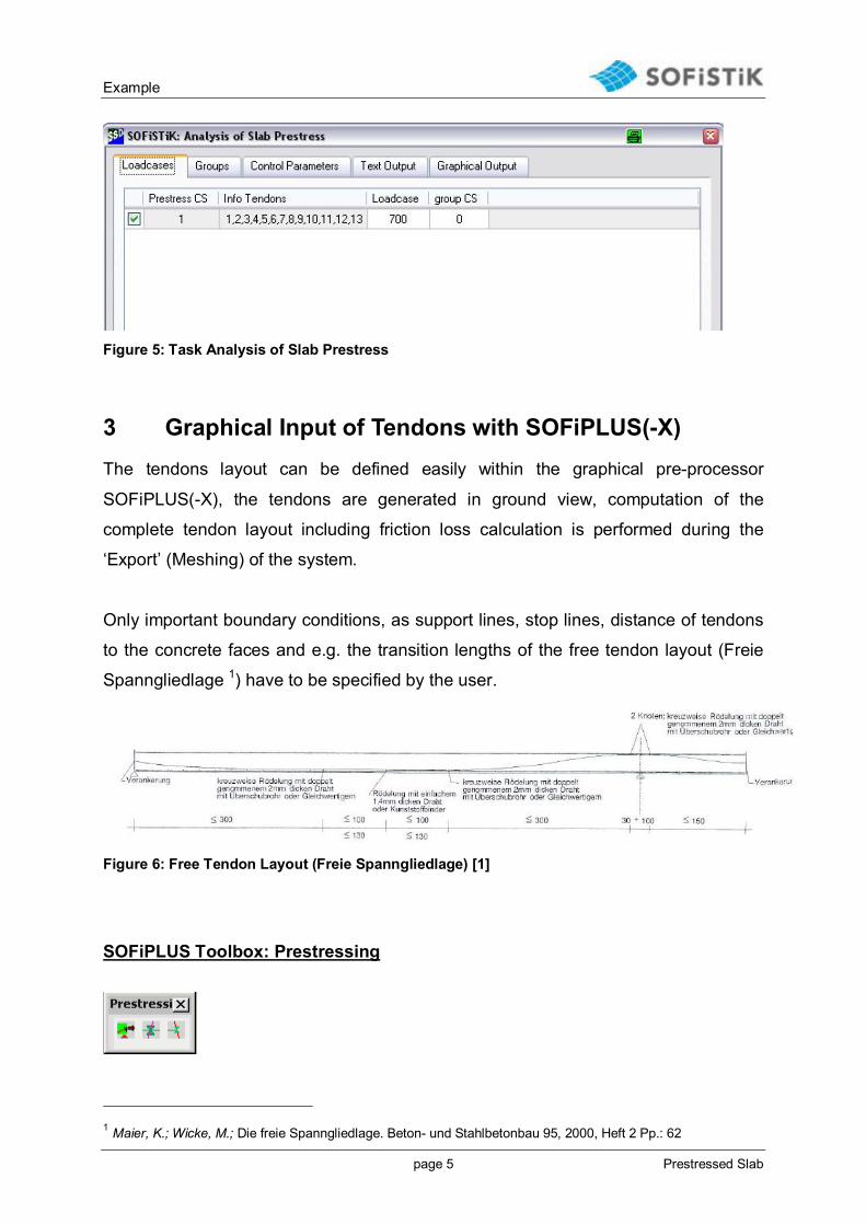
Task: Analysis of Slab Prestress
The Task Analysis of Slab Prestress computes the resulting forces for existing slab
tendons, per default the loadcase number 700 and the action P is assigned to the
results.
Example
page 5 Prestressed Slab
Figure 5: Task Analysis of Slab Prestress
3 Graphical Input of Tendons with SOFiPLUS(-X) The tendons layout can be defined easily within the graphical pre-processor
SOFiPLUS(-X), the tendons are generated in ground view, computation of the
complete tendon layout including friction loss calculation is performed during the
‘Export’ (Meshing) of the system.
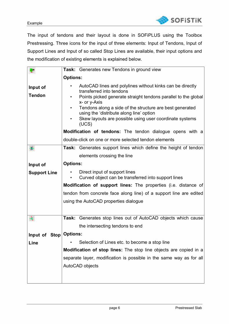
Only important boundary conditions, as support lines, stop lines, distance of tendons
to the concrete faces and e.g. the transition lengths of the free tendon layout (Freie
Spanngliedlage 1) have to be specified by the user.
Figure 6: Free Tendon Layout (Freie Spanngliedlage) [1]
SOFiPLUS Toolbox: Prestressing
1 Maier, K.; Wicke, M.; Die freie Spanngliedlage. Beton- und Stahlbetonbau 95, 2000, Heft 2 Pp.: 62
Example
page 6 Prestressed Slab
The input of tendons and their layout is done in SOFiPLUS using the Toolbox
Prestressing. Three icons for the input of three elements: Input of Tendons, Input of
Support Lines and Input of so called Stop Lines are available, their input options and
the modification of existing elements is explained below.
Input of
Tendon
Task: Generates new Tendons in ground view
Options:
• AutoCAD lines and polylines without kinks can be directly transferred into tendons
• Points picked generate straight tendons parallel to the global x- or y-Axis
• Tendons along a side of the structure are best generated using the ‘distribute along line’ option
• Skew layouts are possible using user coordinate systems (UCS)
Modification of tendons: The tendon dialogue opens with a
double-click on one or more selected tendon elements
Input of Support Line
Task: Generates support lines which define the height of tendon
elements crossing the line
Options:
• Direct input of support lines • Curved object can be transferred into support lines
Modification of support lines: The properties (i.e. distance of
tendon from concrete face along line) of a support line are edited
using the AutoCAD properties dialogue
Input of Stop Line
Task: Generates stop lines out of AutoCAD objects which cause
the intersecting tendons to end
Options:
• Selection of Lines etc. to become a stop line Modification of stop lines: The stop line objects are copied in a
separate layer, modification is possible in the same way as for all
AutoCAD objects

Example
page 7 Prestressed Slab
SOFiPLUS Tendon Dialogue
Double clicking on one or more selected tendon elements opens the SOFiPLUS
Dialog Tendon, here the necessary input for tendon parameters is possible.
The arrow on one end of the tendon indicates the ‘left’ end
Figure 7: Tendon dialogue
§ Prestress direction: Definition of active and passive anchor side § Kind of prestressing § Tendon geometry: Free tendon geometry or cubic spline geometry can be
selected § Straight part in top position: Length of the straight part over highpoints
(colums etc.), only for free tendon layout § Transition: Transition length of the free tendon layout, only for free tendon
layout § Distances of axis to upper and lower concrete edge

Example
page 8 Prestressed Slab
Figure 8: Formula for transition lenght [1]
Figure 9: The Points tab allows for geometry modification of single tendons
Figure 10: Input of tendon distance for a support line

Example
page 9 Prestressed Slab
Figure 11: Stop Line (red line)
4 Analysis and Post Processing After the definition of the tendons with SOFiPLUS, the SSD is used to control the
further analysis and the post processing, the Task Linear Analysis is used to
calculate all loadcases except prestress, here the aforementioned Task Analysis of
Slab Prestress is employed. The reports of all calculation steps are managed using
the URSULA button of the SSD, further reference on the SSD can be found via Menu
‘Help’ Quick Reference.
The complete tendons friction calculation results are available as <projectname>_tnd.plb via the Menu ‘Open’ of URSULA
Figure 12: Report of tendon calculation
Example
page 10 Prestressed Slab
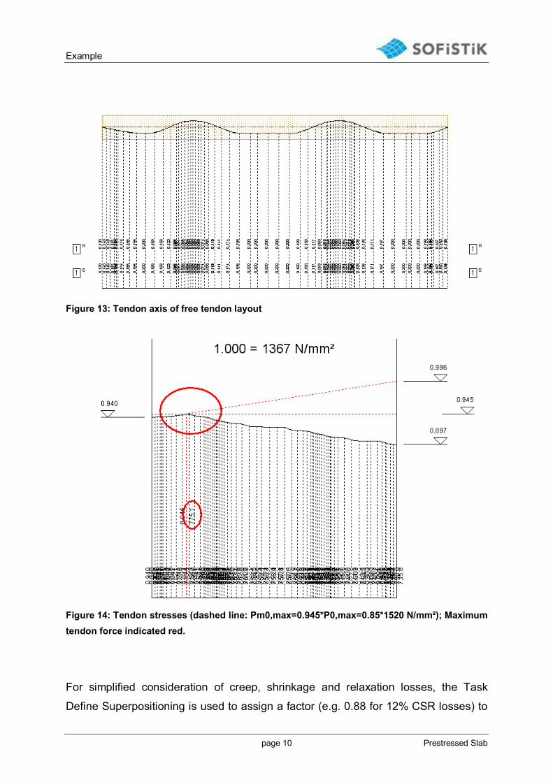
Figure 13: Tendon axis of free tendon layout
Figure 14: Tendon stresses (dashed line: Pm0,max=0.945*P0,max=0.85*1520 N/mm²); Maximum tendon force indicated red.
For simplified consideration of creep, shrinkage and relaxation losses, the Task
Define Superpositioning is used to assign a factor (e.g. 0.88 for 12% CSR losses) to

Example
page 11 Prestressed Slab
the prestressing loadcase in the automatically generated loadcase combinations (e.g.
EC2-2004, ULS and SLS combination).
Figure 15: Factor for simple CSR consideration
The design in ULS and SLS of the prestressed slab is carried our using the standard
design Tasks: Design ULS/SLS – area elements.
Remark on punching design for prestressed slabs:
Using BEMESS 11.90-23 the inclination and force of tendons crossing the punching
area is automatically detected and considered in the punching design and checks,
the mean compressive stress sigma-cd is considered for EC2-2004 and DIN 1045-1,
selecting extensive text output for punching the prestress reduction force Vpd and
the individual contributions can be checked.

Example
page 12 Prestressed Slab
Figure 16: Extensive BEMESS output for punching design with tendons
Example
page 13 Prestressed Slab
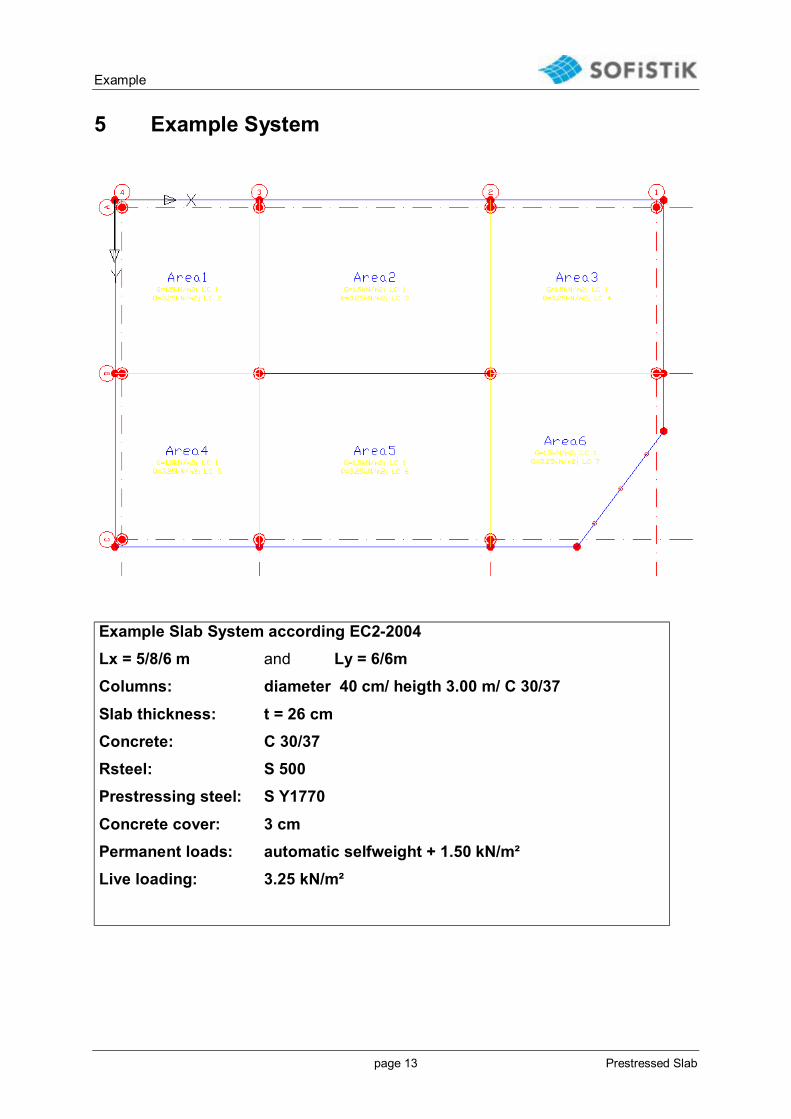
5 Example System
Example Slab System according EC2-2004 Lx = 5/8/6 m and Ly = 6/6m Columns: diameter 40 cm/ heigth 3.00 m/ C 30/37
Slab thickness: t = 26 cm Concrete: C 30/37 Rsteel: S 500 Prestressing steel: S Y1770
Concrete cover: 3 cm Permanent loads: automatic selfweight + 1.50 kN/m² Live loading: 3.25 kN/m²


