+ All Categories
Home > Documents > Quick Start Guide: QNET 2.0 VTOL - meqtronics.com · Quick Start Guide: QNET 2.0 VTOL STEP 1 Check...

Quick Start Guide: QNET 2.0 VTOL - meqtronics.com · Quick Start Guide: QNET 2.0 VTOL STEP 1 Check...

Date post: 06-Jul-2018
Category:
Upload: lyque
View: 246 times
Download: 0 times
Share this document with a friend
2
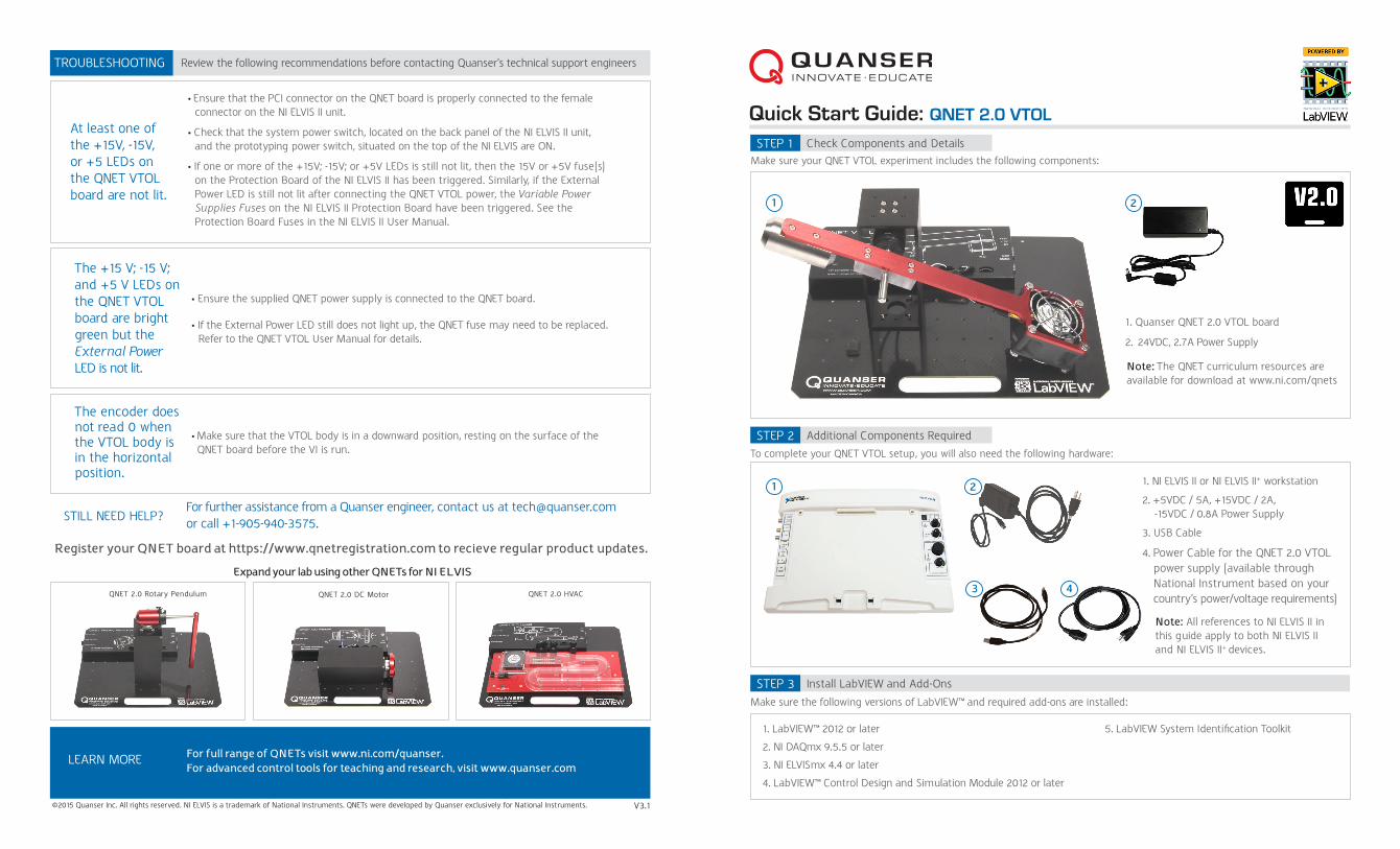
Quick Start Guide: QNET 2.0 VTOL Check Components and Details STEP 1 Make sure your QNET VTOL experiment includes the following components: Review the following recommendations before contacting Quanser’s technical support engineers TROUBLESHOOTING STILL NEED HELP? For further assistance from a Quanser engineer, contact us at [email protected] or call +1-905-940-3575. The +15 V; -15 V; and +5 V LEDs on the QNET VTOL board are bright green but the External Power LED is not lit. The encoder does not read 0 when the VTOL body is in the horizontal position. Ensure the supplied QNET power supply is connected to the QNET board. If the External Power LED still does not light up, the QNET fuse may need to be replaced. Refer to the QNET VTOL User Manual for details. Make sure that the VTOL body is in a downward position, resting on the surface of the QNET board before the VI is run. 2 Additional Components Required Install LabVIEW and Add-Ons STEP 2 STEP 3 To complete your QNET VTOL setup, you will also need the following hardware: Make sure the following versions of LabVIEW™ and required add-ons are installed: 1. LabVIEW™ 2012 or later 2. NI DAQmx 9.5.5 or later 3. NI ELVISmx 4.4 or later 4. LabVIEW™ Control Design and Simulation Module 2012 or later At least one of the +15V, -15V, or +5 LEDs on the QNET VTOL board are not lit. Ensure that the PCI connector on the QNET board is properly connected to the female connector on the NI ELVIS II unit. Check that the system power switch, located on the back panel of the NI ELVIS II unit, and the prototyping power switch, situated on the top of the NI ELVIS are ON. If one or more of the +15V; -15V; or +5V LEDs is still not lit, then the 15V or +5V fuse(s) on the Protection Board of the NI ELVIS II has been triggered. Similarly, if the External Power LED is still not lit after connecting the QNET VTOL power, the Variable Power Supplies Fuses on the NI ELVIS II Protection Board have been triggered. See the Protection Board Fuses in the NI ELVIS II User Manual. Expand your lab using other QNETs for NI ELVIS ©2015 Quanser Inc. All rights reserved. NI ELVIS is a trademark of National Instruments. QNETs were developed by Quanser exclusively for National Instruments. V3.1 LEARN MORE For full range of QNETs visit www.ni.com/quanser. For advanced control tools for teaching and research, visit www.quanser.com 1. Quanser QNET 2.0 VTOL board 2. 24VDC, 2.7A Power Supply QNET 2.0 Rotary Pendulum 5. LabVIEW System Identification Toolkit QNET 2.0 DC Motor QNET 2.0 HVAC Note: The QNET curriculum resources are available for download at www.ni.com/qnets Register your QNET board at https://www.qnetregistration.com to recieve regular product updates. 1 4 1 2 1. NI ELVIS II or NI ELVIS II + workstation 2. +5VDC / 5A, +15VDC / 2A, -15VDC / 0.8A Power Supply 3. USB Cable 4. Power Cable for the QNET 2.0 VTOL power supply (available through National Instrument based on your country’s power/voltage requirements) Note: All references to NI ELVIS II in this guide apply to both NI ELVIS II and NI ELVIS II + devices. 3
Transcript

Quick Start Guide: QNET 2.0 VTOL

Check Components and DetailsSTEP 1Make sure your QNET VTOL experiment includes the following components:

Review the following recommendations before contacting Quanser’s technical support engineersTROUBLESHOOTING

STILL NEED HELP?

For further assistance from a Quanser engineer, contact us at [email protected] or call +1-905-940-3575.

The +15 V; -15 V; and +5 V LEDs on the QNET VTOL board are bright green but the External Power LED is not lit.

The encoder does not read 0 when the VTOL body is in the horizontal position.

• Ensure the supplied QNET power supply is connected to the QNET board.

• If the External Power LED still does not light up, the QNET fuse may need to be replaced. Refer to the QNET VTOL User Manual for details.

• Make sure that the VTOL body is in a downward position, resting on the surface of the QNET board before the VI is run.

2

Additional Components Required

Install LabVIEW and Add-Ons

STEP 2

STEP 3

To complete your QNET VTOL setup, you will also need the following hardware:

Make sure the following versions of LabVIEW™ and required add-ons are installed:

1. LabVIEW™ 2012 or later

2. NI DAQmx 9.5.5 or later

3. NI ELVISmx 4.4 or later

4. LabVIEW™ Control Design and Simulation Module 2012 or later

At least one of the +15V, -15V, or +5 LEDs on the QNET VTOL board are not lit.

• Ensure that the PCI connector on the QNET board is properly connected to the female connector on the NI ELVIS II unit.

• Check that the system power switch, located on the back panel of the NI ELVIS II unit, and the prototyping power switch, situated on the top of the NI ELVIS are ON.

• If one or more of the +15V; -15V; or +5V LEDs is still not lit, then the 15V or +5V fuse(s) on the Protection Board of the NI ELVIS II has been triggered. Similarly, if the External Power LED is still not lit after connecting the QNET VTOL power, the Variable Power Supplies Fuses on the NI ELVIS II Protection Board have been triggered. See the Protection Board Fuses in the NI ELVIS II User Manual.

Expand your lab using other QNETs for NI ELVIS

©2015 Quanser Inc. All rights reserved. NI ELVIS is a trademark of National Instruments. QNETs were developed by Quanser exclusively for National Instruments. V3.1

LEARN MORE For full range of QNETs visit www.ni.com/quanser.For advanced control tools for teaching and research, visit www.quanser.com

1. Quanser QNET 2.0 VTOL board

2. 24VDC, 2.7A Power Supply

QNET 2.0 Rotary Pendulum

5. LabVIEW System Identification Toolkit

QNET 2.0 DC Motor QNET 2.0 HVAC

Note: The QNET curriculum resources are available for download at www.ni.com/qnets

Register your QNET board at https://www.qnetregistration.com to recieve regular product updates.

1

4

1 2 1. NI ELVIS II or NI ELVIS II+ workstation

2. +5VDC / 5A, +15VDC / 2A, -15VDC / 0.8A Power Supply

3. USB Cable

4. Power Cable for the QNET 2.0 VTOL power supply (available through National Instrument based on your country’s power/voltage requirements)

Note: All references to NI ELVIS II in this guide apply to both NI ELVIS II and NI ELVIS II+ devices.

3

24V 2.0A+15V-15V+5V

External Power

Assembly

Setup HardwareTesting the QNET VTOL

STEP 4

STEP 5STEP 6

F Connect the QNET VTOL power supply.To assemble the QNET VTOL , please read the following instructions carefully. For full details, see the QNET VTOL User Manual. G Power on the NI ELVIS II using the power switch on the back of the unit. The READY and ACTIVE LEDs on the top NI ELVIS II panel should briefly light, and the READY LED stays on.

HG

D EC

FClick on the STOP button to stop running the VI.

Click on the white arrow to run the VI.

Make sure the VTOL body is in the downward position, resting on the QNET board.

The charts show the elevation of the VTOL body measured by the encoder, and the propeller motor current command. The charts should

resemble those shown here. If not, consult the troubleshooting section at the end of this guide.

Open the LabVIEW Virtual Instrument (*.vi) found under the Quick Start folder

Select the device name to match your NI ELVIS II device as shown in the

NI Measurement & Automation Explorer in the Device control.

Bring the support arm into the upright position and align the screw holes on the bottom of the support with the four holes indicated on the bottom of the QNET board.

A BMake sure your PC, NI ELVIS II, and QNET board are powered ON.

Open the Quick Start folder from the VTOL folder in the QNET Resources. The QNET Resources are available for download from www.ni.com/qnets.

A B

Remove the four thumbscrews located on the bottom of the VTOL support.

DTighten the four thumb screws to secure the arm to the QNET board.

When assembled, the system should resemble the QNET VTOL shown in Step 1.

C

Slide the PCI connector at the back of the QNET board into the female connector on the NI ELVIS II.

Place the handle on the front of the QNET board over the bracket located on the front of the NI ELVIS II.

Connect the NI ELVIS II power supply to the back panel of the NI ELVIS II.

Use the NI ELVIS II USB cable to connect the NI ELVIS II unit to your computer.

D

A

E

Ensure that the NI ELVIS II power switch is in the OFF position.

24V 2.0A+15V-15V+5V

External Power

24V 2.0A+15V-15V+5V

External Power

PC

CB

HEnsure that the +15V, -15V, +5V, and the External Power LEDs on the QNET board are lit.

Power on the QNET VTOL by turning the NI ELVIS II prototyping board power switch. The POWER LED next to the switch should light up.

24V 2.0A+15V-15V+5V

External Power

I


Recommended