44
Quick Start Guide 00825-0100-2555, Rev AB January 2020 Rosemount ™ 2555 Solids Level Switches Capacitance Probe

Quick Start Guide00825-0100-2555, Rev AB
January 2020
Rosemount™ 2555 Solids Level Switches
Capacitance Probe

ContentsIntroduction................................................................................................................................. 3
Mechanical installation.................................................................................................................8
Electrical installation.................................................................................................................. 12
Configuration.............................................................................................................................17
Troubleshooting........................................................................................................................ 36
Maintenance.............................................................................................................................. 41
Quick Start Guide January 2020
2 Quick Start Guide

1 Introduction
The level switch detects the presence and absence of a process media at itsinstallation point, and reports it as a switched electrical output.
NoteOther language versions of this Quick Start Guide can be found atEmerson.com/Rosemount.
1.1 Safety messages
NOTICE
Read this manual before working with the product. For personal and systemsafety, and for optimum product performance, ensure you thoroughlyunderstand the contents before installing, using, or maintaining thisproduct.
For technical assistance, contacts are listed below:
Customer Central
Technical support, quoting, and order-related questions.
• United States - 1-800-999-9307 (7:00 am to 7:00 pm CST)
• Asia Pacific- 65 777 8211
North American Response Center
Equipment service needs.
• 1-800-654-7768 (24 hours a day — includes Canada)
• Outside of these areas, contact your local Emerson representative.
WARNING
Physical access
Unauthorized personnel may potentially cause significant damage to and/ormisconfiguration of end users’ equipment. This could be intentional orunintentional and needs to be protected against.
Physical security is an important part of any security program andfundamental to protecting your system. Restrict physical access byunauthorized personnel to protect end users’ assets. This is true for allsystems used within the facility.
January 2020 Quick Start Guide
Quick Start Guide 3

WARNING
Failure to follow safe installation and servicing guidelines could result indeath or serious injury.
• Ensure the level switch is installed by qualified personnel and inaccordance with applicable code of practice.
• Use the level switch only as specified in this manual. Failure to do so mayimpair the protection provided by the level switch.
Explosions could result in death or serious injury.
• In explosion-proof/flameproof, non-Incendive/type n, and dust ignition-proof installations, do not remove the housing cover when power isapplied to the level switch.
• The housing cover must be fully engaged to meet flameproof/explosion-proof requirements.
Electrical shock could cause death or serious injury.
• Avoid contact with the leads and terminals. High voltage that may bepresent on leads can cause electrical shock.
• Ensure the power to the level switch is off, and the lines to any otherexternal power source are disconnected or not powered while wiring thelevel switch.
• Ensure the wiring is suitable for the electrical current and the insulation issuitable for the voltage, temperature, and environment.
Process leaks could result in death or serious injury.
• Ensure the level switch is handled carefully. If the process seal isdamaged, gas or dust might escape from the silo (or other vessel)
Any substitution of non-recognized parts may jeopardize safety. Repair(e.g. substitution of components) may also jeopardize safety and is notallowed under any circumstances.
• Unauthorized changes to the product are strictly prohibited as they mayunintentionally and unpredictably alter performance and jeopardizesafety. Unauthorized changes that interfere with the integrity of thewelds or flanges, such as making additional perforations, compromiseproduct integrity and safety. Equipment ratings and certifications are nolonger valid on any products that have been damaged or modifiedwithout the prior written permission of Emerson. Any continued use ofproduct that has been damaged or modified without the writtenauthorization is at the customer’s sole risk and expense.
Quick Start Guide January 2020
4 Quick Start Guide

CAUTION
The products described in this document are NOT designed for nuclear-qualified applications.
• Using non-nuclear qualified products in applications that requirenuclear-qualified hardware or products may cause inaccurate readings.
• For information on Rosemount nuclear-qualified products, contact yourlocal Emerson Sales Representative.
Individuals who handle products exposed to a hazardous substance canavoid injury if they are informed of and understand the hazard.
• If the product being returned was exposed to a hazardous substance asdefined by Occupational Safety and Health Administration (OSHA), acopy of the required Safety Data Sheet (SDS) for each hazardoussubstance identified must be included with the returned level switch.
1.2 ApplicationsA Rosemount™ 2555 Solids Level Switch is used for monitoring the level ofbulk materials in all types of containers and silos.
Typical applications are:
• Building materials— Lime, extruded polystyrene foam (XPS), molding sand, etc.
• Food and beverage— Milk powder, flour, salt, etc.
• Plastics— Plastic granulates, etc.
• Timber
• Chemicals
The level switch has a threaded, flanged, or Tri Clamp process connection formounting it onto a silo (or other vessel). You can mount it on a side wall ofthe silo, so that it is level with the filling limit to be monitored. Alternatively,if it has an extended length, mount it vertically on top of a silo to monitor themaximum filling limit.
The length of the capacitance probe can be up to 98.4 in. (2.5 m) with a rodextension tube or up to 787 in. (20 m) with an extension rope.
The use of a sliding sleeve is recommended so that the switching point canbe changed easily during the live operation of the level switch.
January 2020 Quick Start Guide
Quick Start Guide 5

Figure 1-1: Typical Installation Examples
A
B
C
D
E
F
GH I
J
B
K
A. Inactive length to reach distance from silo wallB. Inactive length due to long mounting nozzleC. Short length (full-silo detection)D. Short length (on-demand detection)E. Short length (empty-silo detection)F. Application in down pipe
G. Inactive length to bring active probe to required levelH. Inactive length and sliding sleeve for adjustable height
I. Rope version (full-silo detection)J. Rope version (empty-silo detection)
K. Optional sliding sleeve
Active and inactive probe lengths
The active length is always inside the silo and generates an electrical fieldbetween the probe and the silo wall. With active shield technology, the RFmeasurements are unaffected by product build-up on the probe. Theinactive length is used to extend the overall probe length.
NoteSee the Rosemount 2555 Product Data Sheet for extended length options.
Quick Start Guide January 2020
6 Quick Start Guide

1.3 Measurement principles
Using the principle of measuring capacitance through RF (Radio Frequency),the presence or absence of a solids medium is detected by monitoring thechange in capacitance between the probe and the container wall.
When the solids medium in the vessel (silo) falls away from the probe level, itcauses an increase in capacitance that is detected by the electronics and theoutput switches to indicate an 'uncovered' state.
When the solids medium in the vessel (silo) rises and covers the rod, itcauses a decrease of capacitance that is detected by the electronics and theoutput switches to indicate a 'covered' state.
The electrical output will vary depending on the electronics selected whenthe Rosemount 2555 was ordered.
January 2020 Quick Start Guide
Quick Start Guide 7

2 Mechanical installation
2.1 Mounting considerationsBefore mounting the level switch on a silo (or other vessel), review the safetyand pre-mounting sections.
2.1.1 Safety
General safety
1. Installation of this equipment shall be carried out by suitably trainedpersonnel, in accordance with the applicable code of practice.
2. If equipment is likely to come into contact with aggressivesubstances, it is the user’s responsibility to take suitable precautionsthat prevent it from being adversely affected, thus ensuring the typeof protection is not compromised.
a. Aggressive substances: Acidic liquids or gases that mayattack metals or solvents that may affect polymeric materials.
b. Suitable precautions: Regular checks as part of routineinspections or establishing from a material's data sheet that itis resistant to specific chemicals.
3. It is the responsibility of the installer to:a. Take protective measures, such as fitting an angled shield
(reverse V shape) to the silo or selecting an extension tubeoption, when there are high mechanical forces.
b. Ensure that the process connection is tightened by thecorrect amount of torque and sealed to prevent processleaks.
4. Technical dataa. The Rosemount 2555 Product Data Sheet has all the technical
specifications. See Emerson.com/Rosemount for otherlanguage versions.
Hazardous area safety
The Rosemount 2555 Product Certifications document has safetyinstructions and control drawings for hazardous area installations. SeeEmerson.com/Rosemount for other language versions.
Quick Start Guide January 2020
8 Quick Start Guide

2.1.2 Tightening threaded process connections
When tightening the threaded process connection of a Rosemount 2555:
• Use an open-ended wrench on the hexagonal boss of the level switch orthe sliding sleeve.
• Never tighten by using the housing.
• Do not exceed the maximum torque of 80 Nm.
2.1.3 Sliding sleeve
Tighten both M8 screws with a torque of 20 Nm to establish a seal andmaintain the process pressure.
2.1.4 Mechanical load
The load at points A and B (Figure 2-1) must not be exceeded. All ratings arefor 104 °F (40 °C).
Figure 2-1: Maximum Mechanical Loads
A
B
Table 2-1: Maximum Mechanical Loads
Rosemount 2555S
Rosemount 2555R
Rod version:
Rope version:
A: 125 Nm
4 kN tensile load
B: 20 Nm
Rosemount 2555M
Rosemount 2555P
Rod version:
Rope version:
A: 525 Nm
40 kN tensile load
B: 90 Nm
Rosemount 2555E
Rosemount 2555V
Rod version:
Rope version:
A: 525 Nm
10 kN tensile load
B: 20 Nm
2.1.5 Orientation of cable glands
When the level switch is mounted horizontally, ensure the cable glands arepointed downwards to avoid water getting inside the housing. Unusedconduit entries must be completely sealed with a suitably rated stopping(blanking) plug.
January 2020 Quick Start Guide
Quick Start Guide 9
2.1.6 Future maintenance
It is advisable to grease the screws of the housing cover (lid) when acorrosive atmosphere is present. This will help prevent difficulties when thecover needs to be removed during future maintenance tasks.
2.1.7 Hygienic applications
The food-grade materials are suitable for use under normal and predictablehygienic applications (according to directive 1935/2004 Art.3). There arecurrently no hygienic certifications for the Rosemount 2555.
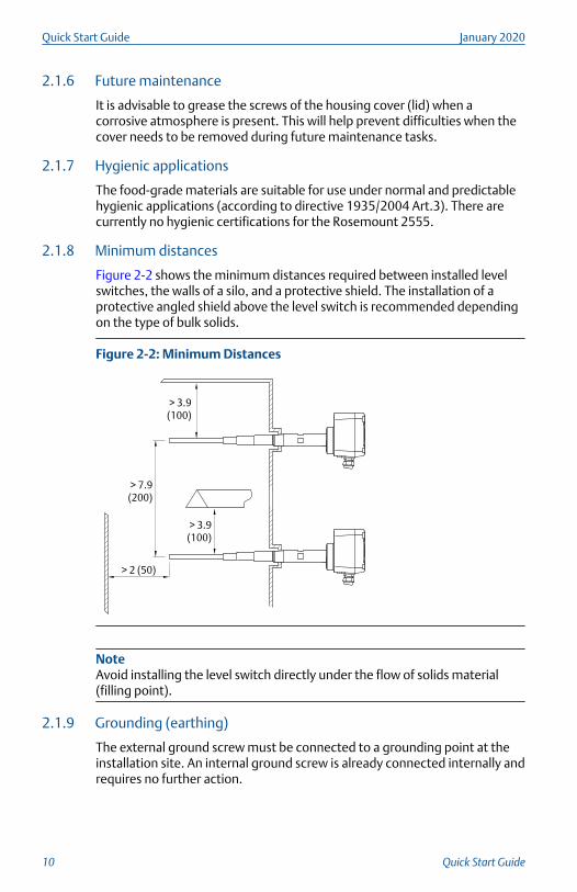
2.1.8 Minimum distances
Figure 2-2 shows the minimum distances required between installed levelswitches, the walls of a silo, and a protective shield. The installation of aprotective angled shield above the level switch is recommended dependingon the type of bulk solids.
Figure 2-2: Minimum Distances
> 2 (50)
> 3.9 (100)
> 3.9 (100)
> 7.9 (200)
NoteAvoid installing the level switch directly under the flow of solids material(filling point).
2.1.9 Grounding (earthing)
The external ground screw must be connected to a grounding point at theinstallation site. An internal ground screw is already connected internally andrequires no further action.
Quick Start Guide January 2020
10 Quick Start Guide

See Wiring the level switch for further information about grounding(earthing) the level switch.
2.2 Mounting the level switchFigure 2-3 shows how the level switch should be mounted.
Figure 2-3: Correct and Incorrect Mounting
> 1.8 (50)A
> 1.8
(50)A
> 1.8
(50)A
> 1.8
(50)A
OK
OK OK
OK
E F G
C D
B
A. Active probeB. Mounting the level switch at an angle helps solids material to fall away
and prevent build-upC. Correct installation: The inactive length is correctly used with a long
socketD. Correct installation: The inactive length is correctly used even though
there is a build-up of solids materialE. Incorrect installation: The active probe is inside the socketF. Incorrect installation: The active probe is covered by a build-up of
material and is not detecting the true levelG. Incorrect installation: The active probe is located where solids material
would remain, even in an empty silo
January 2020 Quick Start Guide
Quick Start Guide 11

3 Electrical installation
3.1 Wiring considerations
NoteSee the Rosemount 2555 Product Data Sheet for the full electricalspecifications.
3.1.1 Handling
In cases of improper handling or handling malpractice, the electrical safetyof the device cannot be guaranteed.
3.1.2 Protective earthing
Before any electrical installation, the device must be connected to theprotective earthing terminal inside the housing.
3.1.3 Installation regulations
Local regulations or VDE 0100 (Regulations of German ElectrotechnicalEngineers) must be observed.
When using 24 V supply voltage, an approved power supply with reinforcedinsulation to mains is required.
3.1.4 Fuse
Use a fuse as stated in the connection diagrams.
For details, see Wiring the level switch.
3.1.5 Residual Current Circuit Breaker (RCCB) protection
In case of a defect, the distribution voltage must automatically be cut-off byan RCCB protection switch to protect against indirect contact withdangerous voltages.
3.1.6 Power supply
Power supply switch
A voltage disconnection switch must be provided near the device.
Supply voltage
Compare the supply voltage applied with the specifications given on theelectronic module and nameplate before switching on the device.
Quick Start Guide January 2020
12 Quick Start Guide

3.1.7 Wiring
Field wiring cables
The diameter has to match the clamping range of the used cable gland.
The cross-section has to match the clamping range of the connectionterminals and the maximum current must be considered.
All field wiring must have insulation suitable for at least 250 Vac.
The temperature rating must be at least 194 °F (90 °C).
Use a shielded cable when there are electrical interferences present that arehigher than stated in the EMC standards. Otherwise, an unshieldedinstrumentation cable can be used.
Wiring diagram
The electrical connections are made in accordance with the wiring diagram.
Guiding the cables in the terminal box
The field wiring cables must be cut to a length to be able to properly fit theminto the terminal box.
3.1.8 Cable glands
The screwed cable gland and stopping plug must have the followingspecifications:
• Ingress protection IP67
• Temperature range from -40 °C to +80 °C
• Hazardous area certification (depending on where the unit is installed)
• Pull relief
Ensure the screwed cable gland safely seals the cable and is tight enough toprevent water ingress. Unused conduit or cable entries must be sealed with astopping (blanking) plug.
A strain relief must be provided for the field wiring cables when the device isinstalled with the factory-provided cable glands.
Cable glands and conduit system for ATEX or IECEx
The installation must comply with the regulations of the country where thelevel switch is installed.
Unused entries have to be closed with suitably rated stopping (blanking)plugs.
Where available, the factory-provided parts must be used.
January 2020 Quick Start Guide
Quick Start Guide 13
The diameter of the field wiring cable must match the clamping range of thecable clamp.
If factory-provided parts are not used, the following must be ensured:
• The parts must have an approval adequate to the approval of the levelsensor (certificate and type of protection).
• The approved temperature range must be between the minimumambient temperature of the level sensor and the maximum ambienttemperature of the level sensor increased by 10 K.
• The parts must be mounted according to the instructions of themanufacturer.
3.1.9 Conduit system
When a threaded conduit system is used instead of a cable gland, theregulations of the country must be observed. The conduit must have a ½-in.NPT tapered thread to match a NPT threaded conduit entry of the levelswitch and comply with ANSI B 1.20.1. Unused conduit entries must beclosed tightly with a metal stopping (blanking) plug.
Conduit system for FM
The regulations of the country must be observed. The flameproof seals andstopping (blanking) plugs must have an adequate type approval and atemperature range of at least -40 to 176 °F (–40 to +80 °C). In addition, theymust be suitable for the conditions and correctly installed. Where available,the original provided parts of the manufacturer must be used.
3.1.10 Connection terminals
When preparing cable wires for connection to terminals, the wire insulationmust be stripped to show no more than 0.31 in. (8 mm) of the copperstrands. Always check that the power supply is disconnected or switched-offto avoid coming into contact with dangerous live parts.
3.1.11 Relay and transistor protection
Provide protection for relay contacts and output transistors to protect thedevice against inductive load surges.
3.1.12 Static charging
The Rosemount 2555 must be grounded to avoid a static electrical build-up.This is particularly important for applications with pneumatic conveying andnon-metallic containers.
Quick Start Guide January 2020
14 Quick Start Guide

3.1.13 Opening the lid
Before opening the lid, ensure no dust deposits, no airborne dusts, and nohazardous atmosphere are present.
Do not remove the lid (cover) while circuits are alive.
3.1.14 External equipotential bonding terminal
Connect with equipotential bonding of the plant.
Figure 3-1: External Equipotential Bonding Terminal
A
A. Equipotential bonding terminal on the Rosemount 2555
3.2 Wiring the level switch
Figure 3-2: Connections
1
A
B
1 2 3 4 5 6 7 8
A. Protective conductor terminalB. Connection terminals
Wiring the power supply and the DPDT relay
Power supply:
• 21 to 230 Vac (50/60 Hz) or Vdc ±10%
• 1.5 VA or 1.5 W
January 2020 Quick Start Guide
Quick Start Guide 15

• Fuse on power supply: maximum 10 A, 250 V, HBC, fast or slow
Signal output:
• Floating relay DPDT:— Maximum 250 Vac, 8 A (non-inductive)
— Maximum 30 Vdc, 5 A (non-inductive)
• Fuse on signal output:— Maximum 10 A, 250 V, HBC, fast or slow
Figure 3-3: Power Supply and Signal Output
1 1 2 3 4 5 6 7 8
PE+ -L N
A
B
A. Power supplyB. Signal output
Quick Start Guide January 2020
16 Quick Start Guide

4 Configuration
4.1 User interface
Figure 4-1: Features of the User Interface
1 1 2 6 7 8 3 4 5
CAL
TEST
MENU
LED
Display
Table 4-1: LEDs
Green Relay is energized
Yellow Relay is de-energized
Red Maintenance (flashing) or error (not flashing)
4.2 Powering up the first time (calibration)Calibration automatically starts when the Rosemount 2555 is powered upfor the first time. If the level switch is powered off and then on again, thiscalibration procedure is not repeated when starting up.
Prerequisites
• The level switch must be correctly mounted and wired.
• The level of the solids material must be below the probe.
Procedure
1. Ensure the level of the solids material is not covering the probe.
January 2020 Quick Start Guide
Quick Start Guide 17

2. Power up the level switch.
a) The calibration is in progress when the displays indicate CALand the LED is red and flashing.
b) After approximately 45 seconds, the calibration completesand indicates the actual measured capacitance and the letteru is indicated for the uncovered probe status.
3. Check the quick-start settings.
a) Use the quick-start menu (see Quick-start menus) to reviewand change the factory settings for Fail Safe High and Low,signal output delay, and sensitivity.
Postrequisites
The Rosemount 2555 is now calibrated and ready to be configured.
4.3 Measurement modeThe level switch indicates the actual measured capacitance and the status ofthe signal output.
Display(1) LED Description
*** u
*** c
Green or yellow(2) Actual measuredcapacitance in pF (3).
Actual signal output:states uncovered probe uor covered probe c.
(1) If unexpected messages are displayed, see Maintenance and error messages.(2) Green or yellow depending on setting of FSH and FSL.(3) Resolution is 0.1 pF (< 100 pF) or 0.5 pF (> 100 pF). If values are > 100 pF, a dot
behind the number means 0.5 pF (e.g. 100. means 100.5 pF)
NoteIf the actual measured capacitance is higher than electronics can measure(i.e. > 400 pF with sensitivity setting >= 2 pF or > 100 pF with sensitivitysetting <= 1 pF), the level switch will state 400c or 100c. The measurementis valid, since the actual capacitance is well above the calibrated switchpoint. Also, the output signal indicates the probe is covered by showing c.
Quick Start Guide January 2020
18 Quick Start Guide

4.4 Quick-start menus
NoteThe LED is flashing red while the quick-start menu is displayed.
Table 4-2: In Measurement Mode
MENU
When the level switch is in Measurement mode, press and hold theMENU button for 3 seconds to enter the quick-start menu. If Code isdisplayed, a Lock Code is required. Set the code number with the arrowbuttons and confirm with the Menu button. Then press and hold theMenu button again for 3 seconds to enter the quick-start menu.
While in the quick-start menu, press and hold the Menu button for 3seconds to return to Measurement mode.
Press the Menu button for less than 1 second to store a new setting andproceed to the next menu item.
CAL TEST
Use the arrowed buttons, CAL and TEST, to increase and decrease thevalue of a setting.
Table 4-3: Quick-start Menus
Display Description Menu item
A. FSH(1)
FSL
Fail Safe High
Fail Safe Low
Signal output, Fail safe setting
B. ALL(1)
C-U
U-C
Covered-to-uncovered-to-covered probe
Covered-to-uncovered probe
Uncovered-to-covered probe
Signal output, Delay direction
C. 0.5(1)
2
5
to 60
Seconds Signal output, Delay time
Adjustable in steps (increment in 5seconds).
D. 0.5
1
2(2)
4
10
15
25
35
pF Sensitivity
Required capacitance increasebetween uncovered probe (aftercalibration) and switch to outputcovered probe.
Change the preset value only ifrequired by the application. SeeGuide to push-button calibration.
The D menu item is not valid, and isnot shown if Manual calibration(menu item G) is set to ON.
(1) Factory default setting.
January 2020 Quick Start Guide
Quick Start Guide 19

(2) Standard factory setting is 2 pF. Optional standard settings if ordered.
4.4.1 FSH and FSL settings
• FSH:— Use the FSH setting for full-silo detection applications.
— Power failure or line break is considered by the electronics to be asfull signal (as protection against overfilling).
• FSL:— Use the FSL setting for empty-silo detection applications.
— Power failure or line break is considered by the electronics to be asempty signal (as protection against running dry).
Figure 4-2: FSH and FSL settings
6 7 8 3 4 5 6 7 8 3 4 5 6 7 8 3 4 5 6 7 8 3 4 5 6 7 8 3 4 5
FSL FSH FSL FSH
Yellow LED Yellow LED Power failureGreen LED Green LED
Quick Start Guide January 2020
20 Quick Start Guide

4.5 Guide to push-button calibrationPush-button calibration needs to be done if Power up calibration at firsttime operation was not successful or the unit was changed to anotherlocation or a significant change of DK was present after changing thematerial.
Calibration with uncovered probe only This is the simplest method and,therefore, is recommended.
If a too small change of capacitancebetween uncovered and covered probeis present, a higher sensitivity can beselected (1 pF or 0.5 pf).
For a higher change of capacitance andexcessive build-up, the sensitivity can bereduced (4 pF or more).
For the calibration procedure, seePowering up the first time (calibration).
Calibration with uncovered and coveredprobe
Sets the switching-point in the middlebetween uncovered and covered probecapacitances. It ensures the maximumswitching distance to both uncoveredand covered probe capacitance, andhelps to prevent material build-up.
For materials with low DK values andtherefore smaller capacitancedifferences for covered and uncoveredstates, this method is recommended.The DK values are not required to beknown.
For the calibration procedure, seePowering up the first time (calibration).
January 2020 Quick Start Guide
Quick Start Guide 21

4.5.1 Push-button calibration for an uncovered probe only
Prerequisites
• The level switch must be correctly mounted and wired.
• The level of the solids material must be below the probe.
Procedure
1. Review the stages in the calibration procedure.
A C D
B
A. Capacitance of uncovered probeB. SensitivityC. Switching-pointD. Capacitance of covered probe
2. Ensure the solids material is not covering the probe.
3. Set the sensitivity.
This is only required in certain circumstances. See Guide to push-button calibration.
Use the quick-start menu item D to set the sensitivity. See Quick-start menus.
4. Press and hold the CAL button for three seconds. CAL
The LED is red and flashing when the calibration is started.
a) Wait approximately 10 seconds until the calibration iscompleted.
b) The display then indicates the actual measured capacitanceand a u for the uncovered probe state.
Quick Start Guide January 2020
22 Quick Start Guide

Need help?If Code is displayed:
1. Enter the code using the arrow buttons and confirm it with the Menubutton.
2. Press and hold the CAL button again for three seconds to restart thecalibration.
If any other messages are displayed, see Maintenance and error messages.
Postrequisites
The Rosemount 2555 is now calibrated and ready to be configured.
January 2020 Quick Start Guide
Quick Start Guide 23

4.5.2 Push-button calibration for uncovered and covered probes
Prerequisites
• The level switch must be correctly mounted and wired.
• The level of the solids material must be below the probe.
Procedure
1. Review the stages in the calibration procedure.
A C D
B
A. Capacitance of uncovered probeB. SensitivityC. Switching-pointD. Capacitance of covered probe
2. Ensure the solids material is not covering the probe.
3. Press and hold the CAL button for three seconds. CAL
The LED is red and flashing when the calibration is started.
a) Wait approximately 10 seconds until the calibration iscompleted.
b) The display then indicates the actual measured capacitanceand a u for the uncovered probe state.
4. Make a note of the actual measured capacitance displayed when theprobe is uncovered.
5. Make a note of the actual measured capacitance displayed when theprobe is covered.
For vertical mounting (rope version), the solids material must coverthe probe by 4 - 8 in. (10 - 20 cm).
Quick Start Guide January 2020
24 Quick Start Guide

6. Set the sensitivity.
Calculate the capacitance difference between the uncovered andcovered probe.
Set the sensitivity as follows (quick-start menu item D):
Horizontal mounting Vertical mounting
(rope version)
Capacitance(1) Sensitivity(2) Capacitance(1) Sensitivity(3)
0.8 to 1.5 pF 0.5 pF 0.5 to 1.0 pF 0.5 pF
1.5 to 3 pF 1 pF 1.0 to 2 pF 1 pF
3 to 6 pF 2 pF 2 to 4 pF 2 pF
6 to 15 pF 4 pF 4 to 10 pF 4 pF
15 to 23 pF 10 pF 10 to 15 pF 10 pF
23 to 38 pF 15 pF 15 to 25 pF 15 pF
38 to 53 pF 25 pF 25 to 35 pF 25 pF
> 53 pF 35 pF > 35 pF 35 pF
(1) Capacitance difference between uncovered and covered probe.(2) The difference between uncovered and covered should be well above
the sensitivity setting, i.e. approximately > 50 percent.(3) The difference between uncovered and covered does not need to be
above the sensitivity setting, since with the capacitance will increasewith rising solids material.
If different materials need to be measured in the same bin withoutrecalibration, the sensitivity must be set for the material with thelowest DK.
Need help?If Code is displayed:
1. Enter the code using the arrow buttons and confirm it with the Menubutton.
January 2020 Quick Start Guide
Quick Start Guide 25

2. Press and hold the CAL button again for three seconds to restart thecalibration.
If any other messages are displayed, see Maintenance and error messages.
Postrequisites
The Rosemount 2555 is now calibrated and ready to be configured.
4.6 Resetting the first power-up calibrationAn already calibrated level switch can be reset to perform a new power-upcalibration. This may be needed if installing it in a different silo or if it has tobe pre-configured before being shipped.
To do a reset:
1. Press and hold the CAL button for three seconds.
2. Switch off the voltage supply when CAL appears on the display.
Since the calibration was started, but not successfully finished, itautomatically starts again when the level switch is powered-up.
NoteOnly the calibration is affected. The settings in the menus are not changed.
4.7 Data storage of the last valid calibration valuesIf the power supply is switched off, the last valid calibration values arestored, and are still valid, when power is switched on again.
4.8 Manual function test (proof test)The Rosemount 2555 can self-test the internal electronics and externalconnected signal evaluation.
Prerequisites
The proof-test must be operated in Measurement mode.
Procedure
1. Press and hold the TEST button for three seconds. TEST
The display shows TEST when the testing is started.
2. Wait approximately 20 seconds until the test is completed.
During the test, the LED turns yellow and the signal output relaychanges state for approximately 10 seconds before returning tonormal operation.
Quick Start Guide January 2020
26 Quick Start Guide

Need help?If Code is displayed:
1. Enter the code using the arrow buttons and confirm it with the Menubutton.
2. Press and hold the CAL button again for three seconds to restart thecalibration.
If ERR is displayed, see Maintenance and error messages.
Postrequisites
The Rosemount 2555 is now calibrated and ready to be configured.
4.9 Advanced menu
NoteThe LED will be red and flashing while the menu is displayed.
Table 4-4: In Measurement Mode
MENU
When the level switch is in Measurement mode, press and hold theMENU button for 10 seconds to enter the Advanced menu. Keepholding the MENU button even when the Quick-start menu (item:A.FSx) appears after 3 seconds.
If Code is displayed, a Lock Code is required. Set the code numberwith the arrow buttons, CAL and TEST, and confirm with the MENUbutton. Then, press and hold the MENU button again for 10seconds to enter the Advanced menu.
While in the Advanced menu, press and hold the menu button for3 seconds to return to Measurement mode.
Press the MENU button for less than 1 second to store a newsetting and proceed to the next menu item.
CAL TEST
Use the arrowed buttons, CAL and TEST, to increase and decreasethe value of a setting.
4.9.1 Auto recalibration
NoteThe LED is red and flashing while the menu is displayed.
January 2020 Quick Start Guide
Quick Start Guide 27

Table 4-5: Auto Recalibration Menu (Advanced Menu)
Display Description Menu item
F.(1) OFF(2)
ON
Auto recalibration to uncovered probe.It is possible to commission an already filled silo(covered probe). A proper calibration is notpossible with covered probe. A solution is to doan auto calibration as soon as the silo becomesempty (uncovered probe).
To do this, set Auto recalibration to ON and do apush-button calibration with a covered probe(press and hold the CAL button for 3 seconds).
The level switch will recalibrate (as an uncoveredprobe) when the measured capacitance is 50% ofthe sensitivity setting (menu item D) for morethan two minutes.
Do not set to ON if excessive solids materialbuild-up is present, since this build-up maydecrease the measured capacitance and causean incorrect calibration.
(1) Menu item "F" is not valid, and will not appear on the display, if manualcalibration (Menu item "G") is set to "ON".
(2) Factory default setting.
4.9.2 Manual calibration
NoteThe LED will be red and flashing while the menu is displayed.
Table 4-6: Manual calibration menu (Advanced menu)
Display Description Menu item
G. OFF(1)
ONManual calibration ON/OFF.If set to ON:
• Menu items H,K and L appear.
• Menu items D (Quick-start menu) and F(Auto re-calibration) are no longer valid andare hidden.
• Push-button calibration is not possible (ifCAL button is pressed, the display showsG.ON).
Quick Start Guide January 2020
28 Quick Start Guide

Table 4-6: Manual calibration menu (Advanced menu) (continued)
Display Description Menu item
H. LO(1)
HILow
High
Sensitivity range.Low sensitivity range allows to detect acapacitance change of >= 2 pF.
High sensitivity range allows to detect acapacitance change of >= 0.5 pF.
See also Guide to manual calibration
K. *** pF Switching-point covered-to-uncovered
A C E F
B
A. Capacitance of uncovered probeB. Covered-to-uncovered switching-point (Menu
item "K")C. Hysteresis (Menu item L)
D. Uncovered-to-covered switching-pointE. Capacitance of covered probe
Factory setting for the lowest pF value is 3 pF.
Resolution is 0.1 pF (< 100 pF) or 0.5 pF (> 100pF). If values are > 100 pF, a dot behind thenumber means 0.5 pF (e.g. 100. means 100.5pF).
L. *** pF HysteresisHysteresis can be adjusted to minimize constantswitching of the signal output. This can happenwhen there are unstable capacitancemeasurements due to movement of solidsmaterials.
The lowest value (factory setting) is 0.5/0.2 pF(for Low/High sensitivity).
The maximum value is limited by the maximummeasurable capacitance.
For resolution, see menu item K.
(1) Factory default setting.
January 2020 Quick Start Guide
Quick Start Guide 29

4.9.3 Diagnostics
NoteThe LED is red and flashing while the menu is displayed.
Table 4-7: Diagnostics Menu (Advanced Menu)
Display Description Menu item
M. ON(1)
OFF
Auto Function Test.This function automatically tests the internalelectronics. Testing runs in the background anddoes not affect the normal measurementfunctions.
If a failure is detected:
• The display shows ERR. See Table 5-1.
• The LED turns red and starts flashing.
• The status output relay is de-energized.
N. *** pF Auto calibrated switch-point (covered-to-uncovered).If OR or UR is displayed, there is no validcalibration.
See Troubleshooting.
P. *** pF Auto calibrated switching-point(uncovered-to-covered).If OR or UR is displayed, there is no validcalibration.
See Troubleshooting.
Q. *** °C Minimum Stored Electronics Temperature
R. *** °C Maximum Stored Electronics Temperature
S. *** Software version
T. *** Service dataThis manufacturer data is for the use of Emersonand not covered in this manual.
(1) Factory default setting.
Quick Start Guide January 2020
30 Quick Start Guide

4.9.4 Security and factory reset
NoteThe LED is red and flashing while the menu is displayed.
Table 4-8: Security and Factory Reset Menu (Advanced Menu)
Display Description Menu item
V. *** Lock code.The locking code (password) can be set toprevent unauthorized persons from accessingthe menu system, starting a push-buttoncalibration, or a manual function test (prooftest).
The locking code can be any number from 1 to9999.
A locking code of 000 disables the passwordprotection.
Contact Emerson if a locking code was set buthas been forgotten.
W. NO(1)
YES
Factory reset.This resets all user-entered data to the factorydefaults. The level switch automatically starts acalibration.
(1) Factory default setting.
4.10 Guide to manual calibrationManual calibration is recommended for special purposes.
Calibration with uncovered probe only
This is the simplest method and, therefore, is recommended. It is applicablefor higher DK values, which give a higher change of capacitance between anuncovered and covered probe. The DK value of the solids material is requiredto be known, to set the sensitivity range and an increase to the switching-point.
For the calibration procedure, see Powering up the first time (calibration).
Calibration with uncovered and covered probe
This method is the safest, since it sets the switching-point in the middlebetween uncovered and covered probe capacitances. It ensures themaximum switching distance to both uncovered and covered probecapacitance, and helps prevent material build-up.
For materials with low DK values, and therefore smaller capacitancedifferences for covered and uncovered states, this method is recommended.
January 2020 Quick Start Guide
Quick Start Guide 31

The DK values are required only to be roughly known, so as to set thesensitivity range.
For the calibration procedure, see Powering up the first time (calibration).
Table 4-9: Manual Calibration Guide
DK Sensitivityrange
Calibration:
Uncovered probeonly
Increase toswitching-point
Calibration:
Uncoveredand coveredprobe
< 1.5 - - - -
1.5 to 1.6 High - - Required
1.7 to 1.9 High Recommended +1 pF Possible
2.0 to 2.9 Low Recommended +2 pF Possible
3.0 to 4.9 Low Recommended +4 pF Possible
5.0 to 10 Low Recommended +10 pF Possible
> 10 Low Recommended +15 pF Possible
4.10.1 Manual calibration for an uncovered probe
Prerequisites
• The level switch must be correctly mounted and wired.
• The level of the solids material must be below the probe.
• The signal output delay should be set to 0.5 seconds.
Procedure
1. Review the stages in the calibration procedure.
A C E F
B D
A. Capacitance of uncovered probeB. Increase to switch-pointC. Switching-point for covered-to-uncovered probeD. HysteresisE. Switching-point for uncovered-to-covered probeF. Capacitance of covered probe
2. Ensure the level of the solids material is well below the probe.
Quick Start Guide January 2020
32 Quick Start Guide

3. Set the sensitivity.
Check for the required sensitivity range (low or high) depending onthe material to be measured. Use the calibration guide. See Guide tomanual calibration.
Use the Advanced menu item H to set the sensitivity. See Advancedmenu.
4. Establish the capacitance of the uncovered probe.
a) Navigate to the menu item K in the Advanced menu.
b) Starting with the lowest capacitance (factory setting is 3 pF),increase the displayed capacitance until the output justchanges from covered to uncovered states.
In measurement mode, the actual measured capacitance isdisplayed. This gives an indication of which capacitance the outputchanges from a covered to uncovered state.
If the output has once changed to uncovered and changes back tocovered, the value must be decreased by setting the Hysteresis(menu item L).
5. Set a switch-point for the covered-to-uncovered change.
Use the Advanced menu item K to set the switch-point to theestablished capacitance of an uncovered probe + an increase to theswitch-point. See Advanced menu.
6. Set the Hysteresis.
Use the Advanced menu item L to set the hysteresis. The factorysetting is normally sufficient and does not need to be changed.
Need help?If the actual measured capacitance is close to the limits of what theelectronic can measure (400 pF with sensitivity setting Low or 100 pF withsensitivity setting High). See Maintenance and error messages.
Postrequisites
The Rosemount 2555 is now calibrated and ready to be used.
January 2020 Quick Start Guide
Quick Start Guide 33

4.10.2 Manual calibration for uncovered and covered probes
Prerequisites
• The level switch must be correctly mounted and wired.
• The level of the solids material must be below the probe.
• Manual calibration must be set to ON (Advanced menu, item K)
Procedure
1. Review the stages in the calibration procedure.
A C
D
E F
50% 50%
A. Capacitance of uncovered probeB. Switching-point for covered-to-uncovered probeC. HysteresisD. Switching-point for uncovered-to-covered probeE. Capacitance of covered probe
2. Set the sensitivity.
Check for the required sensitivity range (low or high) depending onthe material to be measured. Use the calibration guide. See Guide tomanual calibration.
Use the Advanced menu item H to set the sensitivity. See Advancedmenu.
3. Make a note of the actual measured capacitance displayed when theprobe is uncovered.
4. Make a note of the actual measured capacitance displayed when theprobe is covered.
For vertical mounting (rope version), the solids material must coverthe probe by 4 to 8 in. (10 to 20 cm).
Quick Start Guide January 2020
34 Quick Start Guide

5. Set a switch-point for the covered-to-uncovered change.
Use the Advanced menu item K to set the switch point to:
(Capacitanceuncovered +
(0.5 * (Capacitancecovered - Capacitanceuncovered))
With Low sensitivity range (Advanced menu item H): If the differencebetween uncovered and covered probe is smaller than 4 pF, seteither to High sensitivity or use a more sensitive probe (longer activeprobe). For rope version only a setting to High sensitivity range ispossible.
With High sensitivity range (Advanced menu item H): If thedifference between uncovered and covered probe is smaller than 1pF, use a more sensitive probe (longer active probe). For ropeversion, call factory.
6. Set the Hysteresis.
Use the Advanced menu item L to set the hysteresis. The factorysetting is normally sufficient and does not need to be changed.
Need help?If the actual measured capacitance is close to the limits of what theelectronic can measure (400 pF with sensitivity setting Low or 100 pF withsensitivity setting High). See Maintenance and error messages.
Postrequisites
The Rosemount 2555 is now calibrated and ready to be configured.
January 2020 Quick Start Guide
Quick Start Guide 35

5 Troubleshooting
5.1 Maintenance and error messagesThe level switch indicates error messages while in measurement mode andduring calibration routines.
Table 5-1: In Measurement Mode
Display LED Description Possible causes andsolutions
UR Flashing red Under Range
Actual measuredcapacitance is lowerthan 3 pF.
Probe is defective orthe probe isincorrectly wired.
The signal outputrelay is de-energized.
OR Flashing red Over Range
After changing thesensitivity from >= 2pF to <= 1 pF.
Actual calibratedcapacitance is higherthan 100 pF andcannot be measuredwith Sensitivitysetting <= 1 pF.Change to Sensitivity2 pF (if DK of thematerial is highenough) orrecalibrate.
ERR Constant red Auto or ManualFunction Test error
Electronics fault.
Replace theelectronics.
The output signalrelay is de-energized.
Quick Start Guide January 2020
36 Quick Start Guide
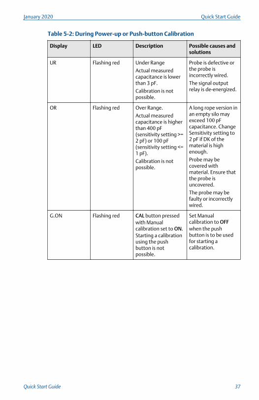
Table 5-2: During Power-up or Push-button Calibration
Display LED Description Possible causes andsolutions
UR Flashing red Under Range
Actual measuredcapacitance is lowerthan 3 pF.
Calibration is notpossible.
Probe is defective orthe probe isincorrectly wired.
The signal outputrelay is de-energized.
OR Flashing red Over Range.
Actual measuredcapacitance is higherthan 400 pF(sensitivity setting >=2 pF) or 100 pF(sensitivity setting <=1 pF).
Calibration is notpossible.
A long rope version inan empty silo mayexceed 100 pFcapacitance. ChangeSensitivity setting to2 pF if DK of thematerial is highenough.
Probe may becovered withmaterial. Ensure thatthe probe isuncovered.
The probe may befaulty or incorrectlywired.
G.ON Flashing red CAL button pressedwith Manualcalibration set to ON.Starting a calibrationusing the pushbutton is notpossible.
Set Manualcalibration to OFFwhen the pushbutton is to be usedfor starting acalibration.
January 2020 Quick Start Guide
Quick Start Guide 37
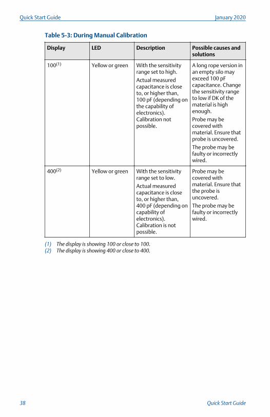
Table 5-3: During Manual Calibration
Display LED Description Possible causes andsolutions
100(1) Yellow or green With the sensitivityrange set to high.
Actual measuredcapacitance is closeto, or higher than,100 pF (depending onthe capability ofelectronics).Calibration notpossible.
A long rope version inan empty silo mayexceed 100 pFcapacitance. Changethe sensitivity rangeto low if DK of thematerial is highenough.
Probe may becovered withmaterial. Ensure thatprobe is uncovered.
The probe may befaulty or incorrectlywired.
400(2) Yellow or green With the sensitivityrange set to low.
Actual measuredcapacitance is closeto, or higher than,400 pF (depending oncapability ofelectronics).Calibration is notpossible.
Probe may becovered withmaterial. Ensure thatthe probe isuncovered.
The probe may befaulty or incorrectlywired.
(1) The display is showing 100 or close to 100.(2) The display is showing 400 or close to 400.
Quick Start Guide January 2020
38 Quick Start Guide

5.2 General itemsTable 5-4: General Items
Situation Behavior of theelectronic
Possible reason Possible solution
Signal output stateis 'probe covered'even though thesolids material isbelow the probe.
The actualmeasuredcapacitance(1) isgreater than thecalibratedswitching-point(2)
for an uncovered-to-covered probechange of state.
The level switch isnot properlycalibrated.
Recalibrate.(3)
Excessive materialbuild-up on activeprobe.
Increase distanceto wall (longerinactive length).
Change theinstallationlocation.
Recalibrate withless sensitivity(3).
Faulty or incorrectprobe wiring.
Check the probewiring (see below).
Signal output stateis 'uncoveredprobe' even thoughthe solids materialis above the probe.
The actualmeasuredcapacitance(3) isless than thecalibratedswitching-point(4)
for an covered-to-uncovered probechange of state.
Calibration wasdone with coveredprobe.
Recalibrate(3).
Calibration wasperformed with asensitivity that wastoo low.
Recalibrate withhighersensitivity(3).
Increase activeprobe length andrecalibrate(3).
Faulty or incorrectprobe wiring.
Check the probewiring (see below).
(1) The value can be seen on the display in Measurement mode.(2) The value can be seen in Advanced menu item P.(3) See the calibration guides.(4) The value can be seen in Advanced menu item N.
5.3 Check the probe wiring
Prerequisites
The power supply to the level switch must be switched off.
Procedure
1. Clean away any deposits on the probe.
2. Take out the electronic board and disconnect internal wires.
January 2020 Quick Start Guide
Quick Start Guide 39

3. Check the orange, yellow, and green/yellow wires with amultimeter.
A
B
C
D
E
A. Orange (probe) and yellow (shield)B. Green/yellow (ground)C. GroundD. ShieldE. Probe
Less than 5 ohm must be present between:
• Orange wire and probe
• Yellow wire and shield
• Green/yellow wire and ground
More than 1 MΩ resistance must be present between:
• Orange and yellow wires
• Orange and green/yellow wires
If other values are present, the wiring of the probe is incorrect ordefective.
Quick Start Guide January 2020
40 Quick Start Guide

6 Maintenance
6.1 Opening the lid (cover)Before opening the lid for maintenance reasons, consider the following:
• Do not remove the lid while circuits are live.
• Ensure that no dust deposits or airborne dusts are present.
• Ensure that rain does not enter the housing.
6.2 Regular checks for safetyTo ensure robust safety in hazardous locations and with electrical safety, thefollowing items must be regularly checked depending on the application:
• Mechanical damage or corrosion of the field wiring cables or any othercomponents (housing side and sensor side).
• Tight sealing of the process connection, cable glands, and enclosure lid.
• Properly connected external PE cable (if present).
6.3 CleaningIf cleaning is required by the application, consider the following:
• The cleaning agent must comply with the materials of the unit (chemicalresistance). Mainly the shaft sealing, lid sealing, cable gland, and thesurface of the unit must be considered.
The cleaning process must be done in a way that:
• The cleaning agent cannot enter into the unit through the shaft sealing,lid sealing, or cable gland.
• No mechanical damage of the shaft sealing, lid sealing, cable gland, orother parts can happen.
A possible accumulation of dust on the unit does not increase the maximumsurface temperature and must therefore not be removed for purposes ofmaintaining the surface temperature in hazardous locations.
6.4 Function testDepending on the application, frequent functional testing may be required.See Manual function test (proof test) for details.
6.5 Production date
The production year is shown on the nameplate.
January 2020 Quick Start Guide
Quick Start Guide 41

6.6 Spare partsRefer to the Rosemount 2555 Product Data Sheet for all spare parts.
Quick Start Guide January 2020
42 Quick Start Guide

January 2020 Quick Start Guide
Quick Start Guide 43

*00825-0100-2555*Quick Start Guide
00825-0100-2555, Rev. ABJanuary 2020
Global HeadquartersEmerson Automation Solutions6021 Innovation Blvd.Shakopee, MN 55379, USA
+1 800 999 9307 or +1 952 906 8888
+1 952 204 8889
North America Regional OfficeEmerson Automation Solutions8200 Market Blvd.Chanhassen, MN 55317, USA
+1 800 999 9307 or +1 952 906 8888
+1 952 204 8889
Latin America Regional OfficeEmerson Automation Solutions1300 Concord Terrace, Suite 400Sunrise, FL 33323, USA
+1 954 846 5030
+1 954 846 5121
Europe Regional OfficeEmerson Automation Solutions EuropeGmbHNeuhofstrasse 19a P.O. Box 1046CH 6340 BaarSwitzerland
+41 (0) 41 768 6111
+41 (0) 41 768 6300
Asia Pacific Regional OfficeEmerson Automation Solutions1 Pandan CrescentSingapore 128461
+65 6777 8211
+65 6777 0947
Middle East and Africa Regional OfficeEmerson Automation SolutionsEmerson FZE P.O. Box 17033Jebel Ali Free Zone - South 2Dubai, United Arab Emirates
+971 4 8118100
+971 4 8865465
Linkedin.com/company/Emerson-Automation-Solutions
Twitter.com/Rosemount_News
Facebook.com/Rosemount
Youtube.com/user/RosemountMeasurement
©2020 Emerson. All rights reserved.
Emerson Terms and Conditions of Sale areavailable upon request. The Emerson logo is atrademark and service mark of Emerson ElectricCo. Rosemount is a mark of one of the Emersonfamily of companies. All other marks are theproperty of their respective owners.


