75
QuickFlick-II Build manual 17th August 2005

QuickFlick-II Build manual
17th August 2005

2

Contents
1 Introduction 5
2 Preparation 7
3 Tail 93.1 Kit Parts Required . . . . . . . . . . . . . . . . . . . . . . . . . . . . . . . .. . . . . . . . . . . . . . . . . . . . . . . 93.2 Additional Parts Required . . . . . . . . . . . . . . . . . . . . . . . . .. . . . . . . . . . . . . . . . . . . . . . . . . . 93.3 Preparation notes . . . . . . . . . . . . . . . . . . . . . . . . . . . . . . . .. . . . . . . . . . . . . . . . . . . . . . . 93.4 Build Notes . . . . . . . . . . . . . . . . . . . . . . . . . . . . . . . . . . . . . .. . . . . . . . . . . . . . . . . . . . 9
3.4.1 Boom cutting . . . . . . . . . . . . . . . . . . . . . . . . . . . . . . . . . . .. . . . . . . . . . . . . . . . . . 93.4.2 Vertical Stabilizer and Rudder preparation . . . . . . . .. . . . . . . . . . . . . . . . . . . . . . . . . . . . . . 93.4.3 Tape hinging the vertical stabilizer . . . . . . . . . . . . . .. . . . . . . . . . . . . . . . . . . . . . . . . . . . 103.4.4 Horizontal stabilizer and elevator . . . . . . . . . . . . . . .. . . . . . . . . . . . . . . . . . . . . . . . . . . 123.4.5 Horizontal stabilizer bonding to boom . . . . . . . . . . . . .. . . . . . . . . . . . . . . . . . . . . . . . . . . 123.4.6 Vertical stabilizer bonding to boom . . . . . . . . . . . . . . .. . . . . . . . . . . . . . . . . . . . . . . . . . 15
4 Fusulage 174.1 Kit Parts Required . . . . . . . . . . . . . . . . . . . . . . . . . . . . . . . .. . . . . . . . . . . . . . . . . . . . . . . 174.2 Additional Parts Required . . . . . . . . . . . . . . . . . . . . . . . . .. . . . . . . . . . . . . . . . . . . . . . . . . . 174.3 Preparation Notes . . . . . . . . . . . . . . . . . . . . . . . . . . . . . . . .. . . . . . . . . . . . . . . . . . . . . . . 174.4 Build Notes . . . . . . . . . . . . . . . . . . . . . . . . . . . . . . . . . . . . . .. . . . . . . . . . . . . . . . . . . . 17
4.4.1 Fusulage side preparation . . . . . . . . . . . . . . . . . . . . . . .. . . . . . . . . . . . . . . . . . . . . . . 174.4.2 Formers . . . . . . . . . . . . . . . . . . . . . . . . . . . . . . . . . . . . . . .. . . . . . . . . . . . . . . . . 194.4.3 Wing mount crossbeam doublers . . . . . . . . . . . . . . . . . . . .. . . . . . . . . . . . . . . . . . . . . . . 204.4.4 Lower deck . . . . . . . . . . . . . . . . . . . . . . . . . . . . . . . . . . . . .. . . . . . . . . . . . . . . . . 214.4.5 Boom mount blocks . . . . . . . . . . . . . . . . . . . . . . . . . . . . . . .. . . . . . . . . . . . . . . . . . 214.4.6 Fusulage reinforcements . . . . . . . . . . . . . . . . . . . . . . . .. . . . . . . . . . . . . . . . . . . . . . . 234.4.7 Joining the boom to the fusulage . . . . . . . . . . . . . . . . . . .. . . . . . . . . . . . . . . . . . . . . . . . 24
4.5 Summary . . . . . . . . . . . . . . . . . . . . . . . . . . . . . . . . . . . . . . . . .. . . . . . . . . . . . . . . . . . 26
5 Wing 275.1 Dihedral braces . . . . . . . . . . . . . . . . . . . . . . . . . . . . . . . . . .. . . . . . . . . . . . . . . . . . . . . . 275.2 Wing bolt blocks . . . . . . . . . . . . . . . . . . . . . . . . . . . . . . . . . .. . . . . . . . . . . . . . . . . . . . . 28
5.2.1 Leading block . . . . . . . . . . . . . . . . . . . . . . . . . . . . . . . . . .. . . . . . . . . . . . . . . . . . . 285.2.2 Trailing block . . . . . . . . . . . . . . . . . . . . . . . . . . . . . . . . .. . . . . . . . . . . . . . . . . . . . 28
5.3 Main wing construction . . . . . . . . . . . . . . . . . . . . . . . . . . . .. . . . . . . . . . . . . . . . . . . . . . . . 295.3.1 Ribs to TE, spars and bottom sheeting . . . . . . . . . . . . . . .. . . . . . . . . . . . . . . . . . . . . . . . . 295.3.2 Frontal webbing . . . . . . . . . . . . . . . . . . . . . . . . . . . . . . . .. . . . . . . . . . . . . . . . . . . 32
5.4 Shaping wing trailing edges . . . . . . . . . . . . . . . . . . . . . . . .. . . . . . . . . . . . . . . . . . . . . . . . . . 325.5 Assembling two wing halves with dihedral brace . . . . . . . .. . . . . . . . . . . . . . . . . . . . . . . . . . . . . . 335.6 Adding half ribs and leading wing mount block . . . . . . . . . .. . . . . . . . . . . . . . . . . . . . . . . . . . . . . 36
5.6.1 First set of half ribs . . . . . . . . . . . . . . . . . . . . . . . . . . . .. . . . . . . . . . . . . . . . . . . . . . 375.6.2 Leading wing bolt block . . . . . . . . . . . . . . . . . . . . . . . . . .. . . . . . . . . . . . . . . . . . . . . 375.6.3 Second set of half ribs . . . . . . . . . . . . . . . . . . . . . . . . . . .. . . . . . . . . . . . . . . . . . . . . 38
5.7 Adding top D box sheeting . . . . . . . . . . . . . . . . . . . . . . . . . . .. . . . . . . . . . . . . . . . . . . . . . . 385.8 Adding rear webbing . . . . . . . . . . . . . . . . . . . . . . . . . . . . . . .. . . . . . . . . . . . . . . . . . . . . . 395.9 Adding Leading edge . . . . . . . . . . . . . . . . . . . . . . . . . . . . . . .. . . . . . . . . . . . . . . . . . . . . . 395.10 Adding Wingtips . . . . . . . . . . . . . . . . . . . . . . . . . . . . . . . . .. . . . . . . . . . . . . . . . . . . . . . 395.11 Adding wing gussetts . . . . . . . . . . . . . . . . . . . . . . . . . . . . .. . . . . . . . . . . . . . . . . . . . . . . . 40
3

4 CONTENTS
5.12 Dihedral brace center sheeting and finishing . . . . . . . . .. . . . . . . . . . . . . . . . . . . . . . . . . . . . . . . . 415.13 Applying Carbon Fiber tow to the wings . . . . . . . . . . . . . . .. . . . . . . . . . . . . . . . . . . . . . . . . . . . 435.14 Drilling wing bolt holes . . . . . . . . . . . . . . . . . . . . . . . . . .. . . . . . . . . . . . . . . . . . . . . . . . . . 44
5.14.1 Leading side wing bolt . . . . . . . . . . . . . . . . . . . . . . . . . .. . . . . . . . . . . . . . . . . . . . . . 445.14.2 Trailing side wing bolt . . . . . . . . . . . . . . . . . . . . . . . . .. . . . . . . . . . . . . . . . . . . . . . . 45
5.15 Drilling fusulage wing bolt holes . . . . . . . . . . . . . . . . . .. . . . . . . . . . . . . . . . . . . . . . . . . . . . . 465.15.1 Primary hole in crossbeam F6 . . . . . . . . . . . . . . . . . . . . .. . . . . . . . . . . . . . . . . . . . . . . 465.15.2 Secondary hole in located in crossbeam F7 . . . . . . . . . .. . . . . . . . . . . . . . . . . . . . . . . . . . . 46
5.16 Finishing . . . . . . . . . . . . . . . . . . . . . . . . . . . . . . . . . . . . . .. . . . . . . . . . . . . . . . . . . . . 475.16.1 Shaping the leading edge . . . . . . . . . . . . . . . . . . . . . . . .. . . . . . . . . . . . . . . . . . . . . . . 47
6 Nose block and canopy 496.1 Nose block . . . . . . . . . . . . . . . . . . . . . . . . . . . . . . . . . . . . . . .. . . . . . . . . . . . . . . . . . . 496.2 Canopy . . . . . . . . . . . . . . . . . . . . . . . . . . . . . . . . . . . . . . . . . .. . . . . . . . . . . . . . . . . . 496.3 Shaping . . . . . . . . . . . . . . . . . . . . . . . . . . . . . . . . . . . . . . . . .. . . . . . . . . . . . . . . . . . . 506.4 Securing the Canopy . . . . . . . . . . . . . . . . . . . . . . . . . . . . . . .. . . . . . . . . . . . . . . . . . . . . . 50
7 Control Rod and Horn Installation 517.1 Control horn installations . . . . . . . . . . . . . . . . . . . . . . . .. . . . . . . . . . . . . . . . . . . . . . . . . . . 51
7.1.1 Rudder control horn installation . . . . . . . . . . . . . . . . .. . . . . . . . . . . . . . . . . . . . . . . . . . 517.1.2 Elevator control horn installation . . . . . . . . . . . . . . .. . . . . . . . . . . . . . . . . . . . . . . . . . . . 53
7.2 Control wire and tube installation . . . . . . . . . . . . . . . . . .. . . . . . . . . . . . . . . . . . . . . . . . . . . . . 54
8 Servo installation 57
9 Covering 61
10 Peg Installation 63
11 Optional Enhancements 6511.1 Rear Fusulage fairing . . . . . . . . . . . . . . . . . . . . . . . . . . . .. . . . . . . . . . . . . . . . . . . . . . . . . 6511.2 Fiberglassing . . . . . . . . . . . . . . . . . . . . . . . . . . . . . . . . . .. . . . . . . . . . . . . . . . . . . . . . . 66
11.2.1 Fusulage Glassing . . . . . . . . . . . . . . . . . . . . . . . . . . . . .. . . . . . . . . . . . . . . . . . . . . 6611.2.2 Canopy Glassing . . . . . . . . . . . . . . . . . . . . . . . . . . . . . . .. . . . . . . . . . . . . . . . . . . . 67
12 Final Assembly 69
13 Flying 71
14 Appendix 7314.1 Making support tubes / sheaths . . . . . . . . . . . . . . . . . . . . .. . . . . . . . . . . . . . . . . . . . . . . . . . . 7314.2 Common product names . . . . . . . . . . . . . . . . . . . . . . . . . . . . .. . . . . . . . . . . . . . . . . . . . . . 7314.3 Conversions . . . . . . . . . . . . . . . . . . . . . . . . . . . . . . . . . . . .. . . . . . . . . . . . . . . . . . . . . . 73
14.3.1 Lengths and sizes . . . . . . . . . . . . . . . . . . . . . . . . . . . . . .. . . . . . . . . . . . . . . . . . . . . 7314.3.2 Weights . . . . . . . . . . . . . . . . . . . . . . . . . . . . . . . . . . . . . .. . . . . . . . . . . . . . . . . . 73
14.4 Further information . . . . . . . . . . . . . . . . . . . . . . . . . . . . .. . . . . . . . . . . . . . . . . . . . . . . . . 74

Chapter 1
Introduction
Welcome to the build manual for the QuickFlick-II, from hereon called the QFII.The QFII was designed out of the need for a builtup discus launch capable glider in the 50” wingspan class that wouldn’t cost much
more than some pocket change and could be built by most peoplewithin a week using rudimentary tools and materials. The current QFIIis the result of no less than five separate iterations of design, progressively improving both the launch performance andglide durationwhile also keeping the build process within the capabilities of most hobbiest workshops.
I’d like to thank you for deciding to build the QFII, I sincerely hope that it brings to you as much enjoyment as it has for me.Paul L DanielsDesigner
5

6 CHAPTER 1. INTRODUCTION

Chapter 2
Preparation
To make building the QFII as efficient as possible, it’s recommended you have the following resources and tools at your disposal
• Workbench of at least 1500 x 500mm in size (for general building)
• Pinnable build surface of at least 800 x 250mm in size (for building the wings)
• Fast CA glue
• Whiteglue (PVA, Aquahere, Weldbond etc)
• Epoxy (may be supplanted by Polyureathane/Gorilla glue etc)
• Balsa Plane (not essential but makes building a lot more plesant)
• Balsa stripper (again, makes building a lot more plesant andaccurate)
• Xacto type No.11 blade knife
• Assortment of clamps and pegs
• Straight-edge rule
• Patience (yes, seriously, patience, your plane will turn out a lot nicer if you don’t rush it )
Throughout this manual there will be references to using various tools to do certain tasks, you are not obliged to follow strictly what isdone in the manual, everyone has their own preferred methods. Gluing of items is additionally a rather subjective affair, the selection ofglues in this manual is based on anticipated loads and stresses that a particular join may be required to take, if you feel that you preferanother selection of glue then certainly go ahead, it is after all a personal judgement call.
Some people may laugh at the requirement of patience, the truth is that after years of building, it would appear that patience canactually speed up a build and result in a better quality finished item, this is because there will be less accidents due to rushing an item(CA is a wonderful glue that bonds fast and strong but it can commit mistakes equally as well).
Examine your kit and make sure that all the parts are includedand none of the items are missing from the laser cut out sheets. Alsocheck that none of the parts in the kit are broken. It helps at times if you mark off the parts on the plan as this gives your mind a chanceto associate where things go.
All dimensions and weights are specified in metric, for reference a conversion table is provided at the end of this manual.
7

8 CHAPTER 2. PREPARATION

Chapter 3
Tail
3.1 Kit Parts Required
• 1.5mm vertical stabilizer
• 1.5mm rudder
• 1.5mm horizontal stabilizer
• 1.5mm elevator
• 6˜7mm CF boom
3.2 Additional Parts Required
• 6mm triangular stock
• 3˜5mm x 6mm x 40mm grooved endgrain pylon mount for horizontal stab
• 3˜5mm x 6mm x 50mm grooved endgrain pylon mount for vertical stab
• 12mm wide clear tape
3.3 Preparation notes
The tail feathers are made of very thin (1.5mm) balsa and subsequently can potentially be damaged very easially on rough landings. Youcan opt to cover them with very light glass (0.75oz or lighter) if you prefer.
3.4 Build Notes
3.4.1 Boom cutting
• Cut the CF boom to a length of 560mm (22”).
– Wrap a couple of layers of masking tape around the boom at the point where it needs to be cut, this will help prevent theboom from splintering. Use an abrasive grinding wheel if possible. Strongly suggest avoid using a hacksaw as this will causea lot of potential splits.
– Keep off cut for using as a sanding guide later in the build process and potentially as the launch peg.
3.4.2 Vertical Stabilizer and Rudder preparation
• If desired, trim off a small amount of the rudder piece from the bottom to prevent snagging and subsequent tearoff.9

10 CHAPTER 3. TAIL
• Bevel the join edge of the rudder using a balsa plane (or othertool) to approximately 45 degrees
• Finish off the surface of both pieces of the vertical stabilizer
• Round the leading edge of the vertical stabilizer
• Feather down the trailing edge of the rudder
3.4.3 Tape hinging the vertical stabilizer
• Hold together the two halves of the vertical stabilizer withthe rudder’s bevelled edge facing out

3.4. BUILD NOTES 11
• Apply a full length of 12mm clear tape to the bevelled side of the two halves and fold it over the join
• Release the two halves from the clamping, the vertical stabilizer will tend to now fold up a little
• Hold the two halves down flat and apply a second piece of 12mm clear tape to the opposite side
• Your rudder is now hinged. There will be approximately a 1mm gap between the two halves, this is normal.
12 CHAPTER 3. TAIL
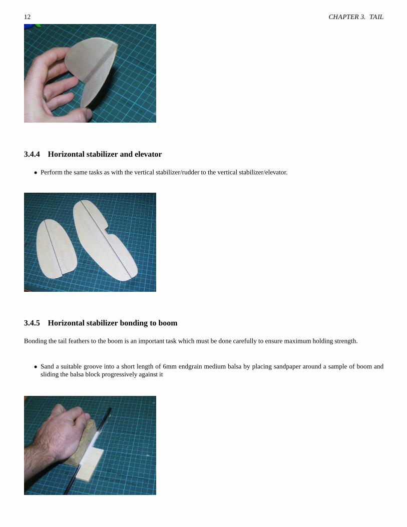
3.4.4 Horizontal stabilizer and elevator
• Perform the same tasks as with the vertical stabilizer/rudder to the vertical stabilizer/elevator.
3.4.5 Horizontal stabilizer bonding to boom
Bonding the tail feathers to the boom is an important task which must be done carefully to ensure maximum holding strength.
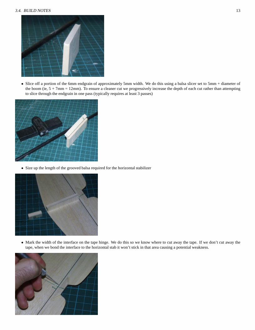
• Sand a suitable groove into a short length of 6mm endgrain medium balsa by placing sandpaper around a sample of boom andsliding the balsa block progressively against it
3.4. BUILD NOTES 13
• Slice off a portion of the 6mm endgrain of approximately 5mm width. We do this using a balsa slicer set to 5mm + diameter ofthe boom (ie, 5 + 7mm = 12mm). To ensure a cleaner cut we progressively increase the depth of each cut rather than attemptingto slice through the endgrain in one pass (typically requires at least 3 passes)
• Size up the length of the grooved balsa required for the horizontal stabilizer
• Mark the width of the interface on the tape hinge. We do this sowe know where to cut away the tape. If we don’t cut away thetape, when we bond the interface to the horizontal stab it won’t stick in that area causing a potential weakness.

14 CHAPTER 3. TAIL
• Glue the interface down onto the horizontal stab with CA. Ensure there’s a good bond and wicking. Try to avoid letting the CAwick too close to the top (where the boom will adhere) otherwise this may interfere with the boom/interface adhesion later.
• Due to the stresses involed on the tail feathers and the thin wood they’re made of (1.5mm), it’s important that the load betweenthe boom and the horizontal stabilizer is spread out. To do this we add some 6x6mm triangular stock on either side of the exitinginterface. Remember to cut away the tape hinge where required.
• Before attempting to bond the boom to the tail feathers it’s important to lightly roughen up the boom using some 200 grit orfinersand paper up to 135mm from the end of the boom. Once you have done this, wash the boom under water and wipe dry, the boomshould appear slightly more matt in appearance where the sandpaper was applied
• Finally, glue the horizontal stabilizer to the boom with theleading edge of the stabilizer at 135mm from the end of the boom.Make sure that the boom is resting evenly and horizontal in the groove. If using CA provide at least a few minutes of bondingtime even if the CA is “fast”.

3.4. BUILD NOTES 15
3.4.6 Vertical stabilizer bonding to boom
• Prepare a 6mm wide end grain balsa interface as with the horizontal stabilizer but instead of a 5˜6mm wide piece we insteadusea piece of 3˜4mm. The reason why we have a thinner piece for therudder is that we need it to be as close to the boom as possibleso that the control rods / bellcranks can remain aligned without requiring offsets.
• Mark the vertical stabilizer approximately 50mm from the base. Ensure that the line is perpendicular to the hinge join.
• Glue on the pylon interface
• Glue on some 2.4mm balsa strip scrap as reinforcement for therudder

16 CHAPTER 3. TAIL
• When bonding the vertical stabilizer to the boom, it’s very important that it is set up at 90 degrees to the existing horizontalstabilizer. There are many different ways that this can be done. We have used some right angle aluminium channelling to whichwe clamped on both the existing horizontal stabilizer and then the vertical stabilizer.
• Your tail feathers are now finished (until later when we add the radio control equipment).
Chapter 4
Fusulage
4.1 Kit Parts Required
• 2 x 3.2mm notched sides
• 2 x 1.5mm forward doublers
• 2 x 3.2mm forward wing mount doublers (F6)
• 2 x 3.2mm rear wing mount doublers (F7)
• Fusulage doublers F1, F2, F3, F4, F5
• 4 x 3.2mm wing mount crossbeams (for wing nuts)
• 1 x 3.2mm Fusulage floor
4.2 Additional Parts Required
• 2 x 58 x 18 x 6mm balsa blocks for holding boom
• 6 x 6mm triangular stock
4.3 Preparation Notes
Keeping the fusulage square and aligned at all times is a goodstart for the rest of the QFII. However do not fret too much if the fusulageis not absolutely perfect. Being a glider, subsequently without a power plant on the nose, allows us to be more lenient in this area. Withall that said, please do still make your best attempt at keeping the fusulage straight.
4.4 Build Notes
4.4.1 Fusulage side preparation
• Start out with the two notched 3.2mm fusulage sides, frontal1.5mm doublers and F2.
• Place F2 into the notches on one side of the fusulage, do not glue in, we are using this as a guide stop for the placement of thedoubler.
17

18 CHAPTER 4. FUSULAGE
• Before applying the glue to the doubler, take note that thereis a slight orientation on the doubler, that is one of the corners is at 90degrees and the other (top) is at 88 degrees. Although this isa slight difference it will make the orientation of the doubler incorrectif applied the wrong way up.
• Apply white glue to the frontal doubler, ensuring good coverage and apply to the notched fusulage side. Make sure that theedgesof the doubler are adhered to the notched fusulage side, thisis important otherwise the doubler can peel off later. Clampingbetween two plates or simply resting some heavy books on the doubler until dry should help (place some balsa shims under theother side of the book if required to ensure a level, even pressure).
• Formers F2,3,4 and F5 are all the same width and should rest at90 degrees (perpendicular) to the fusulage sides.
• Remove F2 from the notches.

4.4. BUILD NOTES 19
• Repeat for the other fusulage side creating amirror image of the first (yes, a couple of times we have done it wrong and ended upwith two left handed sides, very clever!)
4.4.2 Formers
• Glue formers F2,3,4 and F5 to one fusulage side, ensuring that each former is at exactly 90 degrees to the fusulage side. Pleasenote the orientation of the formers, ie,
– F2 should have its semicircular notch facing upwards
– F3 should have the two pushrod slots towards the top
– F4 and F5 should have the boom holes located at the bottom.
• Bring the second fusulage side of the fusulage against the existing side with the formers now attached. Ensure that
– the work surface is flat
– the fusulage sides are held vertical during the gluing process
– the angle between the formers and the fusulage sides remainsat 90 degrees when gluing

20 CHAPTER 4. FUSULAGE
• Obtain F1 and dry fit it to the nose of the fusulage. If all is well the fusulage should evenly bend towards F1. If the bending isuneven and the fusulage takes on a banana appearance then place the fusulage frame into a jig/rigging to keep it rigid and alignedwhile you join F1.
• You have now finished the basic framing up of the fusulage.
4.4.3 Wing mount crossbeam doublers
• Take the two F6 pieces, note that they are marked with ’FRONT’on them, this means that the portion marked ’FRONT’ will beorientated towards the nose of the fusulage.
• Apply white glue to F6, insert and clamp.
– Make sure that F6 is sitting flush with the workbench and the top of the fusulage side
– Make sure you clean up all the excess.
– It’s very important that the bond of F6 to the fusulage side isstrong as there’s going to be a lot of stress at this region.

4.4. BUILD NOTES 21
• Repeat proceedure for the other fusulage side.
4.4.4 Lower deck
• Glue on the 3.2mm lower deck of the fusulage. If the lower deckis slightly longer than your fusulage adjust the position sothatthe excess length extends beyond F1.
4.4.5 Boom mount blocks
The boom mount blocks are made from 6mm soft/medium balsa andrequire a circular groove to be sanded into them of the diameter ofthe boom that is to be used. One of the easiest ways is to sand them down using sandpaper wrapped around a piece of the boom. Somepeople don’t bother with doing this and rely on the gap fillingand strength of the glue rather.

22 CHAPTER 4. FUSULAGE
• Glue in each cheek between F4 and F5.
– Make sure that the cheeks are sitting flush to the bottom and side of the fusulage
– Wipe away any excess glue
– You may want to test fit the boom while the glue is drying to ensure the blocks will hold the boom correctly

4.4. BUILD NOTES 23
• As with F6, glue in the pair of F7 formers on top of the boom cheeks.
4.4.6 Fusulage reinforcements
Although the fusulage is relatively strong in its standard form, it’s best to further add 6mm triangular stock in most corners to furtherincrease the rigidity of the fusulage.
Vertical reinforcements
• All four corners between F2 and F3
• All four corners between F4 and F5

24 CHAPTER 4. FUSULAGE
Horizontal reinforcements
• Reinforcements between F3 and F4 on the floor between the fusulage sides and the base plate.
• Reinforcements between F1 and F2 on the floor between the fusulage sides and the base plate.
4.4.7 Joining the boom to the fusulage
Joining the carbon fiber boom to the fusulage is a very important step which must be done accurately to ensure that when the QFII isfinished the alignment between the wing and the tail feathersis correct.
Preparation
• Prepare your workspace such that there are no nearby items toobstruct your assembly process.
• Check that the build surface you’re going to use is flat, this is very important.
• Obtain some 3.2mm scrap sheet, you will need this to keep the boom level relative to the fusulage when we set it.
• If you’re using 5 minute epoxy it is better to mix up an excess so as to ensure you don’t have insufficient glue half way throughthe joining process as you will not have the time to mix up a second lot

4.4. BUILD NOTES 25
• Have a ruler withmm or finer markings so that you can check for the tail level once the glue has been added
• It is strongly recommended that you donot use CA for this join as it generally lacks the flexibility required to cope with the natureof the stresses encountered. Epoxy or polyureathane glues like “Gorilla glue” are preferred.
Joining Process
• Dry fit the boom into the fusulage. The boom should extend the fully between F5 and F4. The boom should not extend beyond F4
• Place the assembly onto your workbench with the vertical stabilizer just resting over the edge of the bench
• The horizontal stabilizer should still be located over the surface of the bench, this is important as we will judge the alignment ofthe boom based on the distance of the horizontal stabilizer from the surface of the bench
• Weigh down the fusulage with something heavy to ensure it doesn’t lift or move during the gluing process
• Separate the boom from the fusulage after checking that everything appears to be fitting correctly
• Sand the end of the boom lightly with 150˜200 grit paper to remove any sealing agents on the boom as well as providing moreglue surface area
• Mix up your glue as required
• Apply glue, ensure that there is good coverage of glue between the boom and the balsa cheeks between F4 and F5. This join isone of the most critical in the whole fusulage assembly.
• Reinsert boom into fusulage
• Place 3.2mm scrap balsa at the edge of the bench under the boom(this is because the base plate of the fusulage is also 3.2mm,sowe are keeping the boom level)
• Adjust the boom so that the distance from the work bench to thehorizontal stabilizer is the same on both sides
• Leave the boom and fusulage to set for as long as required.
26 CHAPTER 4. FUSULAGE
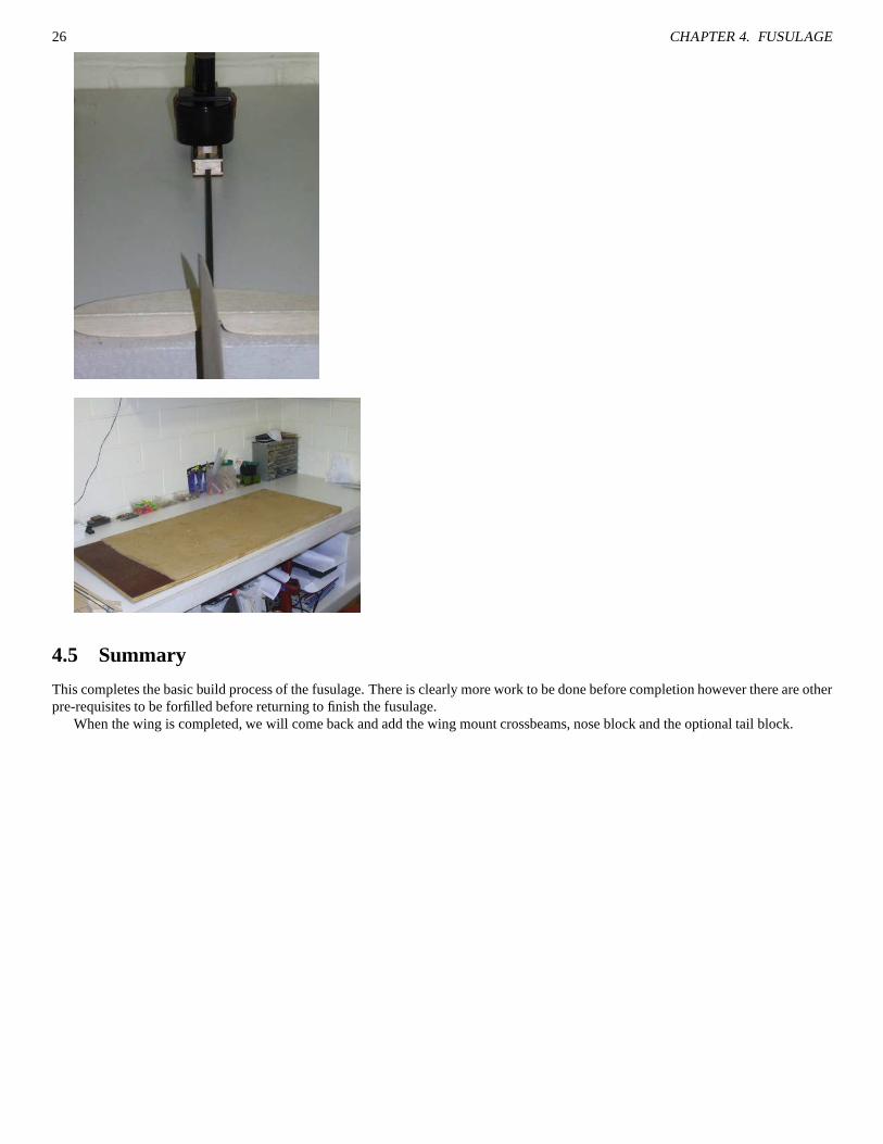
4.5 Summary
This completes the basic build process of the fusulage. There is clearly more work to be done before completion however there are otherpre-requisites to be forfilled before returning to finish thefusulage.
When the wing is completed, we will come back and add the wing mount crossbeams, nose block and the optional tail block.

Chapter 5
Wing
So much of the flight performance and longevity of the QFII DLGdepends on a quality wing build. An incorrectly built wing can stillfly but the level of performance will be reduced due to higher drag. A weakly built wing will not cope with the launch stresses of astrong launch.
5.1 Dihedral braces
Nearly all the forces that want to tear apart your wing will befocused down onto the dihedral brace, consequently the QFIIhas an overengineered brace which may appear to be bulky compared to other kits that you may have built. There are two main braces, each ofnoticably different size.
• Obtain a 3.2mm and 2.4mm brace piece, they should overlay each other perfectly
• If you want to be extra sure about the strength you can apply a length of CF tow between the two pieces when they are gluedtogether
• For gluing it is recommended that you use epoxy thinned down with some metholated spirits (denatured alcohol) in a 1:1:1 ratio(1 part of resin, 1 part of alcohol, 1 part of metho)
• Apply the thinned epoxy mix to one side of the dihedral brace.If you are adding CF tow then make sure that the CF is spreadevenly and that there are no knots or lumps
27

28 CHAPTER 5. WING
• Clamp together the dihedral brace sandwich, don’t worry if some CF tow protrudes from the assembly, this can be trimmed offlater.
• Set assembly aside to cure. If you used thinned epoxy it will appear to be of rubbery consistency for a while and possibly evenbubble a little. Due to the thinning it may not cure as quicklyas the original epoxy (ie, 5 mins), again do not worry, give ita fewhours.
• Repeat this process for the second dihedral brace.
5.2 Wing bolt blocks
The wing bolt blocks hold provide a secure area through whichthe 4mm nylon wing bolts will pass to bolt into the fusulage wing mountcrossbeams.
5.2.1 Leading block
• Take the four pieces of 30 x 20 x 3.2mm balsa and glue together with white glue to form a block 30 x 20 x 12.8mm in size
• Clam and set aside
5.2.2 Trailing block
• Locate the two pieces of 30 x 58 x 3.2mm balsa, you will note that the grain orientation differs.
• Glue both pieces together with white glue to form a 30 x 58 x 6.4mm block
• Clamp and set aside

5.3. MAIN WING CONSTRUCTION 29
5.3 Main wing construction
It is important that your building surface is flat and clean. An uneven building surface will translate to a wing that is difficult to getstraight afterwards. The wings are built in two halves whichare later assembled together using the dihedral braces and wing mountblocks.
5.3.1 Ribs to TE, spars and bottom sheeting
• We use a building surface made from 3/4” building ply laminated with 3˜4mm cork. The plywood keeps flat even in varyinghumidity (so long as it is stored flat) and the cork provides sufficient grip for pins to be held securely.
• Lay the wing plan down on the cork. We like to use a copy of the wing plan that is disposable so that if glue gets on the plan or ifit’s torn we can simply throw it away.
• Start by dry pinning the two parts of the trailing edge (3.2mm) along the plan. Do not glue. Avoid putting pins through the wood,rather rely on adding pins all round forcing the wood to have no room for movement. Pinning through wood is not recommendedbecause it crushes and creates weakness.
• Prepare the bottom D box sheeting by trimming it to a length between the final tip rib (R7) and center line of the wing plan.
30 CHAPTER 5. WING
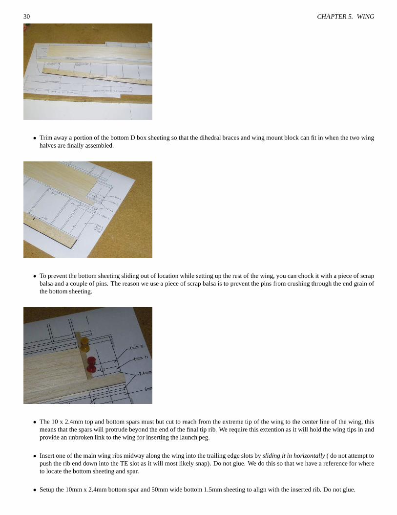
• Trim away a portion of the bottom D box sheeting so that the dihedral braces and wing mount block can fit in when the two winghalves are finally assembled.
• To prevent the bottom sheeting sliding out of location whilesetting up the rest of the wing, you can chock it with a piece ofscrapbalsa and a couple of pins. The reason we use a piece of scrap balsa is to prevent the pins from crushing through the end grainofthe bottom sheeting.
• The 10 x 2.4mm top and bottom spars must but cut to reach from the extreme tip of the wing to the center line of the wing, thismeans that the spars will protrude beyond the end of the final tip rib. We require this extention as it will hold the wing tipsin andprovide an unbroken link to the wing for inserting the launchpeg.
• Insert one of the main wing ribs midway along the wing into thetrailing edge slots bysliding it in horizontally ( do not attempt topush the rib end down into the TE slot as it will most likely snap). Do not glue. We do this so that we have a reference for whereto locate the bottom sheeting and spar.
• Setup the 10mm x 2.4mm bottom spar and 50mm wide bottom 1.5mm sheeting to align with the inserted rib. Do not glue.
5.3. MAIN WING CONSTRUCTION 31
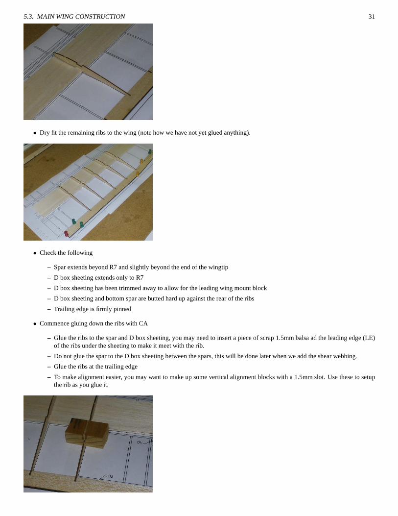
• Dry fit the remaining ribs to the wing (note how we have not yet glued anything).
• Check the following
– Spar extends beyond R7 and slightly beyond the end of the wingtip
– D box sheeting extends only to R7
– D box sheeting has been trimmed away to allow for the leading wing mount block
– D box sheeting and bottom spar are butted hard up against the rear of the ribs
– Trailing edge is firmly pinned
• Commence gluing down the ribs with CA
– Glue the ribs to the spar and D box sheeting, you may need to insert a piece of scrap 1.5mm balsa ad the leading edge (LE)of the ribs under the sheeting to make it meet with the rib.
– Do not glue the spar to the D box sheeting between the spars, this will be done later when we add the shear webbing.
– Glue the ribs at the trailing edge
– To make alignment easier, you may want to make up some vertical alignment blocks with a 1.5mm slot. Use these to setupthe rib as you glue it.

32 CHAPTER 5. WING
• Apply top spar, if the spar is not quite wide enough, make sure spar is aligned with the rear of the rib notch. This cannot beemphasised enough. If the spar is not flush against the rear ofthe notch then the dihedral assembly will not align correctly,subsequently causing potential twists in the wing later.
• Glue top spar to ribs
5.3.2 Frontal webbing
The use of webbing between the spars greatly enhances the stiffness of the wing. Without the webbing the wings will be inclined tobend and twist during launch causing spar compression whichis often fatal.
• Note that with the laser cut kit from LaserArts, all the webbing is numbered. For each rib bay there will be four (4) pieces ofwebbing each (except for ’1’ which has quite a few more), one pair per wing half. The narrorwer pair of the four webbings isintended for the leading side of the spar, this is what we willbe using.
• There is a slight taper on the webbing for bays two (2) throughto seven (7), it is important that you determine which way thistaper is so that you orientate the webbing accordingly. The left hand wing will have the numbers facingtowards the leading edge(the right hand wing will have the numbers facing towards thetrailing edge).
• Insert the webbing between the ribs and apply a liberal amount of CA between the bottom D box sheeting and the webbing, thiswill allow for enough CA to wick behind the webbing and get between the 2.4mm spar and the D box sheeting (the area that wedeliberately did not glue down when gluing the ribs).
• Do not yet install the rear webbings, this will not be done until after the top sheeting is installed (much later)
• Repeat for the other wing, ensure that you build a mirror image wing, rather than two lefts or two rights, again this is somethingwe have done in the past, it’s really not fun, seriously.
5.4 Shaping wing trailing edges
The trailing edges as supplied in the kit are 3.2mm thick, these need to be shaped down using a balsa plane and/or sanding bar to providethe idea airfoil shape in the wing.
• You need to aim to get the TE down to a thickness of no more than 1mm. The thinner you can reliably get the TE the better yourwing will perform because of the lesser losses from drag.

5.5. ASSEMBLING TWO WING HALVES WITH DIHEDRAL BRACE 33
• Be very careful while you are planing/sanding down the TE that you do not pass the stresses into the ribs else they will possiblybreak off at the spar or the TE. The TE should be firmly secured to the bench either via clamp or other methods.
• Do not rush this stage, a simple slip could break a lot of your hard work.
• In order to assist preventing the planer or sanding bar from going too far, it’s recommended that you temporarily attach some0.6mm or 0.8mm wire to the edge of the TE, this stops the planeror sanding bar from going too far.
• Once the shaping is complete it’s recommended that the fine edge is hardened by applying CA to it. A light sanding after the CAhas cured is required to remove any small bubblings or such.
5.5 Assembling two wing halves with dihedral brace
• Take both cured sandwiched dihedral braces and mark their centerlines on both sides
• Place the leading dihedral brace (with the narrower arms) infront of the spars, butted hard against the first rib and clamp
• Cut away the excess spars so that they now meet up with the center line on the dihedral brace
• Remove the clamp and dihedral brace
• Obtain two lengths of scrap 10 x 2.4mm spar offcut and insert between the two existing spars, this is done to help prevent thebrace/spar join from collapsing under high loads
• Trim inserted lengths of spar off to match the lengths of the existing spars (which have been cut to length for the center ofthedihedral).

34 CHAPTER 5. WING
• Obtain the larger dihedral brace (rear) and glue and clamp itto the rear of the spars
– Make sure the brace is butted against the first rib
– Make sure the brace is lying flat with the bottom sheeting (youwill need to rest the brace over the edge of the work-bench/board because of the extention under the brace).
– Use epoxy, Weldbond, PU or other glue with very high lap shearstrength
• Obtain the remaining dihedral brace (frontal), glue and clamp it to the front of the spars
– Make sure the base of the brace is parallel to the base of the previously glued rear brace.
– Make sure the center lines marked on the dihedral brace align
5.5. ASSEMBLING TWO WING HALVES WITH DIHEDRAL BRACE 35
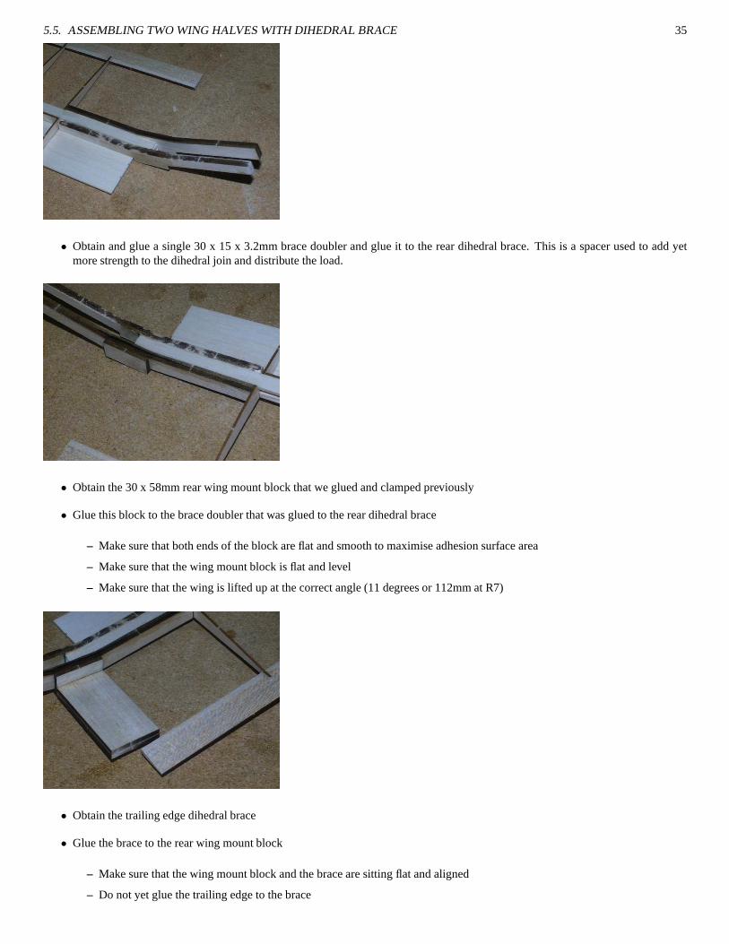
• Obtain and glue a single 30 x 15 x 3.2mm brace doubler and glue it to the rear dihedral brace. This is a spacer used to add yetmore strength to the dihedral join and distribute the load.
• Obtain the 30 x 58mm rear wing mount block that we glued and clamped previously
• Glue this block to the brace doubler that was glued to the reardihedral brace
– Make sure that both ends of the block are flat and smooth to maximise adhesion surface area
– Make sure that the wing mount block is flat and level
– Make sure that the wing is lifted up at the correct angle (11 degrees or 112mm at R7)
• Obtain the trailing edge dihedral brace
• Glue the brace to the rear wing mount block
– Make sure that the wing mount block and the brace are sitting flat and aligned
– Do not yet glue the trailing edge to the brace

36 CHAPTER 5. WING
• Obtain the second wing half and prepare to join it to the first
• Trim the second wing spars to the center line of the dihedral brace as with the previous wing
• Fill the gap between the two spars as with the previous wing
• Trim the trailing edge to meet at the center line of the dihedral brace
• You will need to apply the glue for the two main braces before inserting the spars (highly recommended you use a slow settingglue for this operation as you will need to spend some time setting the wing up to be perfectly aligned.
• Setup both wing halves to be raised 112mm (11 degrees) at R7.
• Place flat blocks under the each wing at an arbitary location to support the wing and keep the incidence of each wing the same.This is an important step, if the incidence of the wing halvesdiffer it will cause the plane to roll. By placing a flat block for thespar and TE to rest on we are forcing the incidence to be constant on each side.
– Check and double check the R7 tip height measurements
– Check that the newly glued brace/spar is clamped and cannot drift out while setting
– Check that the rear wing mount block is lying horizontally along the building surface (it may lift up a little from front toback, this is due to the built in incidence of the dihedral brace set)
• When the dihedral brace bond is dry you can proceed to glue thetrailing edges to the TE dihedral brace (ideally they will alreadybe well lined up with the brace).
5.6 Adding half ribs and leading wing mount block
Once the dihedral brace has been glued and the wing has formedone piece, we need to add in the half-ribs that will go in the regionbetween the last full rib (that our dihedral braces are butted against) and the center.

5.6. ADDING HALF RIBS AND LEADING WING MOUNT BLOCK 37
5.6.1 First set of half ribs
• Obtain four specially laser marked ribs (they will have fouradditional vertical score marks near the spar notches)
• Cut the rib at the rear-most vertical score mark
• Cut the rib at the forward-most vertical score mark
• Discard the center section (containing the spar notches)
• Check for fit, trim thetrailing edge of the rib as required
• Glue the half ribs in 50mm from the first full rib
• Repeat for both sides
5.6.2 Leading wing bolt block
• Obtain the 30x20x17.8mm block we created previously
• Glue block directly to the leading dihedral brace using Epoxy, Weldbond or other high lap shear glue
– Make sure that the wings are resting level
– The block should sit neatly between the two bottom sheetingsand be aligned with the center of the dihedral braces
– Make sure that the rear wing mount block is lying flat, you should be able to make the wing move to the correct alignmentsimply by pressing down on the rear wing mount block to make itsit flat on the building board
– To prevent gluing the wing to your building board, place a sheet of paper underneath the dihedral brace
38 CHAPTER 5. WING
5.6.3 Second set of half ribs
The second set of half ribs are prepared the same way as the first set
• Align the second set of ribs directly against the dihedral / wing mount blocks
• For the rear half of the ribs, align the ribs with the top of thedihedral brace (not the floor)
5.7 Adding top D box sheeting
• Place top D box sheeting butted against the rear spar notch ofthe ribs
• Check that the D box sheeting extends from the inner set of half ribs completely to tip rib R7
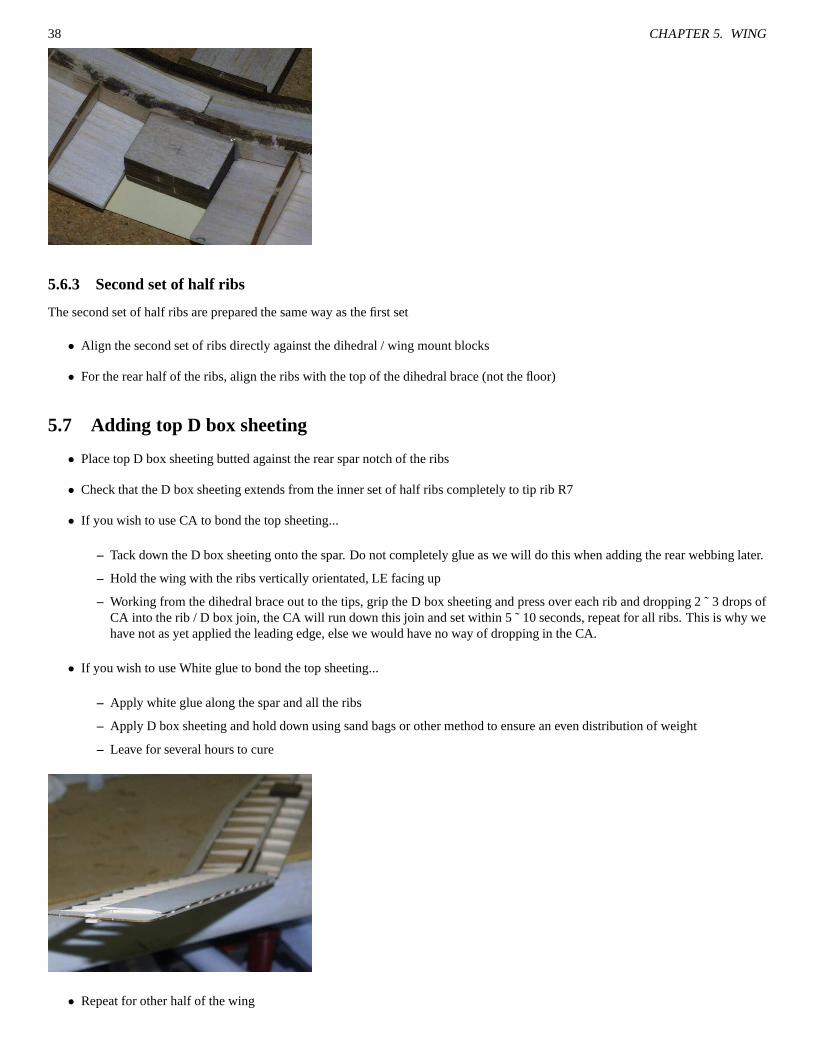
• If you wish to use CA to bond the top sheeting...
– Tack down the D box sheeting onto the spar. Do not completely glue as we will do this when adding the rear webbing later.
– Hold the wing with the ribs vertically orientated, LE facingup
– Working from the dihedral brace out to the tips, grip the D boxsheeting and press over each rib and dropping 2 ˜ 3 drops ofCA into the rib / D box join, the CA will run down this join and set within 5 ˜ 10 seconds, repeat for all ribs. This is why wehave not as yet applied the leading edge, else we would have noway of dropping in the CA.
• If you wish to use White glue to bond the top sheeting...
– Apply white glue along the spar and all the ribs
– Apply D box sheeting and hold down using sand bags or other method to ensure an even distribution of weight
– Leave for several hours to cure
• Repeat for other half of the wing

5.8. ADDING REAR WEBBING 39
5.8 Adding rear webbing
As with the leading side webbing, the rear spar webbings can now be applied using CA, again note that all the numbers on the webbingwill be orientated the same way for each wing half, that is, onthe left hand wing the numbers will face towards the LE, on theright handwing they numbers face towards the TE.
5.9 Adding Leading edge
If all previous components of the assembly are aligned and correctly sized, the leading edge should apply with ease.
• Obtain 6mm square LE stock
• Place LE stock along the notches in the LE of the wing
– The LE stock should rest at approximately 45 degrees
– The LE stock should extend the same length as the D box sheeting (it can over extend but we will be trimming it back later)
– The LE should be straight
• Glue down LE by either applying white glue into the notches before applying the LE stock or wicking CA after applying the LEstock.
• Repeat for other wing
5.10 Adding Wingtips
Each wingtip requires three precut components of 1.5mm.
• Insert the main wingtip between the two protruding spars from R7. It is quite likely that the fit will be tight, insert slowly
• Align the wingtip with the wing trailing edge
• Using 10 x 2.4mm spar offcuts, add support braces on either side of the main spar on both top and bottom sides of the wingtip

40 CHAPTER 5. WING
• Add wingtip doubler pieces to the underside of the wingtip
• Trim off excess 10x2.4mm doublers
5.11 Adding wing gussetts
Guessetts are small triangular pieces of wood which are usedto spread load between two intersecting pieces of assembly.
• Glue gussett between the TE and the first full rib from the center of the wing

5.12. DIHEDRAL BRACE CENTER SHEETING AND FINISHING 41
• Glue gussett between the TE and the last full length rib (R1’s) before the start of the tapering tips
• Repeat for both sides of the wing
5.12 Dihedral brace center sheeting and finishing
• Glue a 30 x 15 x 3.2mm block 12mm forward of the TE dihedral brace.
– This block provides extra support for the wing bolt.
– The block should fit neatly and reach to both half ribs which were previously glued to the rear wing mount block.
• Apply 1.5mm sheeting from the TE dihedral brace through to the leading edge of the D box top sheeting.

42 CHAPTER 5. WING
• Trim the LE stock back to the inner most half ribs
• Insert a short length of LE 6mm square stock between the two half ribs
• Your wing should now appear similar to this

5.13. APPLYING CARBON FIBER TOW TO THE WINGS 43
5.13 Applying Carbon Fiber tow to the wings
Carbon fiber has a very high tensile strength, meaning that itcan endure a lot of pulling forces. To help prevent the wing from bendingand flexing during launch we apply a strip of CF to both sides ofthe wing. With CF on both sides the wing can neither flex up nor down.
The exact method used to bond the CF to the D box sheeting will vary depending both on your preferred glue (CA or thinned epoxy)or the type of CF you’re using (ie, Iron on CF tow will not require gluing). The process described here is for CF tow (12,000 strand)applied with CA.
• Sand down the D box sheeting with 150˜300 grit paper to provide a smooth surface on which the CF can bond to
• Cut a length of CF tow extending from the dihedral center sheeting to the tip rib R7
• Flatten out and groom the CF tow until it is approximately 10˜12mm wide, we need to get the CF tow this wide so that it remainsas flat as possible against the D-box sheeting
• Weigh down the wing so that it cannot move about while settingthe CF to the wing
• Tack down the tow at the wing center, ensure that it has cured sufficiently before proceeding.
• Grip the end of the tow (near the wing tip) and apply moderate tension to it keeping the tow both tight and flat. Keep the towflattened against the D box sheeting
• Starting from the center, working in small 40˜50mm lengths,apply several drops of fast CA to the CF tow, it will tend to pool atfirst and then commence to wick along the CF. Don’t panic aboutthe CA curing, because there is a lot of CA it will tend to staywet for at least 10˜20 seconds, more than enough time to do what is required
• Take a piece of scrap balsa with a straight edge (ie, a spar offcut) and smooth the CA along the CFtowards the tip of the wing.
• Do try to smooth out the CA with too much pressure, we do require a reasonable amount of CA to be present in the CF to ensureit makes a good bond. If we apply too much pressure it will makethe CF go ’dry’.
– As you do this you will possibly notice that the CA begins to literally smoke, this is normal.
– Never draw the smoothing in the opposite direction, if you do this the CF will lift up and create a dreadful mess
– The CF should look shiney and flat
• Keep progressing until you reach the wing tip

44 CHAPTER 5. WING
• Give your completed strip several minutes to fully dry
• Do not touch the strip of CF, if you do there will be white fingerprints left after a few minutes.
• Repeat for both sides of the wing and both wings (4 strips in total)
• Check that the wing’s LE is straight by placing the wing LE down onto a flat surface. The wing should sit very flat to the surface.
5.14 Drilling wing bolt holes
Setting the bolt holes can be a rather fiddly exercise as it’s somewhat difficult to accurately align everything even with good workshoptools.
5.14.1 Leading side wing bolt
• Turn the wing upside down
• Support the wing from underneath with a narrow block (will need to be at least 112mm high)
• Drill a 1.5mm pilot hole 10mm ahead of the leading dihedral brace (the one contained by the D box sheeting) and 15mm in fromthe side of the wing bolt block

5.14. DRILLING WING BOLT HOLES 45
• Ensure that the drill bit is kept upright and that the wing is level during the drill process
• Drill out the pilot hole to the size required for the wingbolt(ie, 4mm)
5.14.2 Trailing side wing bolt
• Drill a 1.5mm pilot hole 20mm in front of the edge of the TE dihedral brace and 15mm from the side. This hole should passdirectly through the additional 30x15x3.2mm block we addedprior to covering the center section with sheeting (see 5.12onpage 41).
• Ensure that the drill bit is kept upright and that the wing is level during the drill process
• Drill out the pilot hole to the size required for the wingbolt(ie, 4mm)
• Test fit the wing bolts in the holes
• Trim away the top 1.5mm sheeting to allow the heads of the bolts to receed beneath the sheeting and rest on the wing blocks
• Pin and CA around the bolt holes on both sides of the bolt blocks (you should be able to reach the blocks from above through theenlarged hole used to accomodate the bolt head). This process will make the balsa become a lot harder and resistant to crushing ifthe bolts slip a little
• Wait 5 to 10 minutes and redrill the holes again to clear out any excess CA that may have built up from the pinning/CA.
46 CHAPTER 5. WING
5.15 Drilling fusulage wing bolt holes
It’s important that the axis wing rests at exactly 90 degreesrelative to the axis of the fusulage. If this isn’t done then there will be varyingstrange flight characterisitcs which will prove hard if not nearly impossible to eliminate. Take your time with this stage, prepare to checkand triple check everything. Drilling of the first hole is notas critical as the second hole since it will be the second holethat will committhe alignment.
5.15.1 Primary hole in crossbeam F6
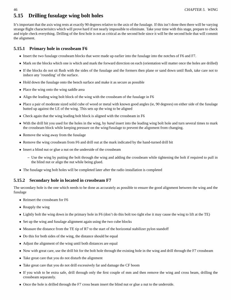
• Insert the two fusulage crossbeam blocks that were made up earlier into the fusulage into the notches of F6 and F7.
• Mark on the blocks which one is which and mark the forward direction on each (orientation will matter once the holes are drilled)
• If the blocks do not sit flush with the sides of the fusulage andthe formers then plane or sand down until flush, take care not toinduce any ’rounding’ of the surface.
• Hold down the fusulage onto the bench surface and make it as secure as possible
• Place the wing onto the wing saddle area
• Align the leading wing bolt block of the wing with the crossbeam of the fusulage in F6
• Place a pair of moderate sized solid cube of wood or metal withknown good angles (ie, 90 degrees) on either side of the fusulagebutted up against the LE of the wing. This sets up the wing to bealigned
• Check again that the wing leading bolt block is aligned with the crossbeam in F6
• With the drill bit you used for the holes in the wing, byhand insert into the leading wing bolt hole and turn several timesto markthe crossbeam block while keeping pressure on the wing/fusulage to prevent the alignment from changing.
• Remove the wing away from the fusulage
• Remove the wing crossbeam from F6 and drill out at the mark indicated by the hand-turned drill bit
• Insert a blind nut or glue a nut on the underside of the crossbeam
– Use the wing by putting the bolt through the wing and adding the crossbeam while tightening the bolt if required to pull inthe blind nut or align the nut while being glued.
• The fusulage wing bolt holes will be completed later after the radio installation is completed
5.15.2 Secondary hole in located in crossbeam F7
The secondary hole is the one which needs to be done as accurately as possible to ensure the good alignment between the wingand thefusulage
• Reinsert the crossbeam for F6
• Reapply the wing
• Lightly bolt the wing down in the primary hole in F6 (don’t do this bolt too tight else it may cause the wing to lift at the TE)
• Set up the wing and fusulage alignment again using the two cube blocks
• Measure the distance from the TE tip of R7 to the start of the horizontal stabilizer pylon standoff
• Do this for both sides of the wing, the distance should be equal
• Adjust the alignment of the wing until both distances are equal
• Now with great care, use the drill bit for the bolt hole through the existing hole in the wing and drill through the F7 crossbeam
• Take great care that you do not disturb the alignment
• Take great care that you do not drill excessively far and damage the CF boom
• If you wish to be extra safe, drill through only the first couple of mm and then remove the wing and cross beam, drilling thecrossbeam separately.
• Once the hole is drilled through the F7 cross beam insert the blind nut or glue a nut to the underside.

5.16. FINISHING 47
5.16 Finishing
5.16.1 Shaping the leading edge
Use a balsa plane and sanding bar to shape the leading edge. It’s suggested that you cut out a small template of the LE shape for themain wing section and use it as your guide for how to shape. Themore accurately you can render the LE to the required shape the betteryour wing efficiency will be.

48 CHAPTER 5. WING

Chapter 6
Nose block and canopy
The exact dimensions of the nose block and canopy, as well as their construction is primarily up to the builder, for this manual we’ll usesoft balsa.
6.1 Nose block
• Make up a nose block either from a solid block of balsa or a lamination of thinner sheets.
• The nose block should be at least 35 x 35 x 35mm
• Glue the block flush to the bottom of the fusulage.
– The excess on the top is deliberate to allow the smooth followon from the canopy.
6.2 Canopy
• Cut an approximate block of at least 6mm balsa for the canopy such that it overlaps the sides by a couple of mm, this gives usclearance for when we’re shaping the final block (12mm can be used if you want an extra round canopy).
49

50 CHAPTER 6. NOSE BLOCK AND CANOPY
6.3 Shaping
If you’re planning on adding the rear fusulage fairing / profiling, it is suggested that you do so at this point so that you can form an evensmoothing
If you’re planning on fiberglassing the fusulage then you canafford to plane and sand back further because the fiberglass will addstrength that would have otherwise been provided by the balsa structure.
• Using a balsa plane, coarsly shape the canopy and the nose to the desired result
• Using a sanding block bring the finish to a finer standard
6.4 Securing the Canopy
• Cut the canopy block at a downward 45 degree angle (from back to front) approximately 20mm from the front. The reason for thedownward angled cut is to provide a natural locking facilitypreventing the canopy from lifting up and flying away
• Glue the 20mm portion to the fusulage
• From a scrap of 3.2mm balsa, cut a small block about 5mm wide with bevelled corners that will fit just in front of F3
• Place this block into position against F3 using some BluTack, Prestick or other plasticine like substance with the surface slightlyraised above the fusulage.
• Add some medium CA to the top of the block
• Insert the large portion of the canopy into place, sliding itunder the previously glued 20mm portion and then lowered down ontothe shaped block
– This will position the block accurately onto the canopy
– Using CA means that you can pull the canopy and block assemblyaway within a few seconds
• Remove the plasticine substance
• Test fit the canopy again

Chapter 7
Control Rod and Horn Installation
To ensure good control characteristics, the control rods must move smoothly and with as little friction as possible as lower friction meansless wear on your servos and faster responses.
Every builder has their preference for what method to use in the setup, we will describe a 2-piece wire setup (per control)using0.6mm (0.024”) Chrome Nickel wire. The wire used in this section is obtained from a fishing store, sold as stainless steel wire leader.There are many different types of stainless steel wire, thisparticular one is pre-straightened and has a spring steel / piano-wire feel. Asan alternative, you could also use 0.8mm (0.030”) or No.13 piano wire.
Wire at the thicknesses used here does not have a lot of compressional stability, that is that it will tend to buckle out under compres-sional forces, this is a highly undesirable trait. We counter this trait by supporting the wire along the length of it withsupport tubes (tubesheath).
As with the wire, there are many options for support tubes. Some suppliers provide sheath with their lengths of wire, other timesyou are required to make it yourself. One option which does appear to work well is to use cigarette wrapper papers (or otherequally thinpaper) that have been gummed and rolled around a piece of wirethat’s slightly larger than the wire that you intend to use for the controlwires (it must be slightly larger to prevent binding). See 14.1 on page 73
7.1 Control horn installations
7.1.1 Rudder control horn installation
• Obtain a surface control horn (1mm ply) and line it up on the rudder with the series of drill holes directly over the hinge line ofthe vertical stabilizer. Move the horn up such that the base of the horn is aligned just slightly below the bottom of the CF boom.
51

52 CHAPTER 7. CONTROL ROD AND HORN INSTALLATION
• Mark the the location of the base of the control horn with a pen, this is where we will cut out a slot that the control horn willbe placed. The control horn must be just slightly lower than the boom so as to allow for the control wire to slide freely withoutbinding when the control horn is pulled inwards towards the boom.
• Trim off the bottom elbow of the control horn, this is required so that the horn doesn’t obstruct into the vertical stabilizer when itis pulled forward
• Using a sharp No.11 blade or similar, cut out a 1mm wide slot inthe location marked

7.1. CONTROL HORN INSTALLATIONS 53
• Insert control horn into slot, test for movement and potential binding against the vertical stabilizer. If all appears good then gluethe control horn in with a small amount of epoxy or medium to thick CA.
7.1.2 Elevator control horn installation
The elevator control horn installation is mostly the same asthe rudder installation however instead of being aligned asclose to the boomas possible, the elevator is typically offset by 6mm from theboom. Take care when cutting the slot for the horn as the elevator is typicallyweaker near the cutaway (for the boom).
• Mark the location and size of the slot to be cut in the elevator.
• Cut out slot and insert control horn
• Check and glue the control horn

54 CHAPTER 7. CONTROL ROD AND HORN INSTALLATION
7.2 Control wire and tube installation
• Cut two lengths of wire from F2 to the end of the boom, this willprovide more than ample length for the installation
• Insert and glue a length of tube between F4 and F5, leave a little protruding from each end, especially the rear of F5 (this is so thatif you put the optional rear fairing block on, you do not run the risk of gluing the tube shut).
• Insert wire into the tube guides between F4 and F5 and push thewire in until it reaches F3
• Slide onto the wire 5 pieces of rolled tube
• Push the first piece to butt up against the protruding tubes emerging from F5
• Tack down the tube with a very small amount of CA
• *WARNING*, be very light with your application of CA, because the tubes are made from paper they can be exceptionally quickto wick the CA into the center of the tube and subsequently glue the tube to the wire.
• Space the rest of the tubes evenly along the boom, following the curve required for the wire to reach its appropriate control horn.
– Tape the wire down near the control horn to make the wire show you what path it prefers to take

7.2. CONTROL WIRE AND TUBE INSTALLATION 55
– Do not force the wire to make agressive bends, this only causes more friction on the run
• For the rudder, the wire must eventually run along the underside of the boom
• For the elevator, the wire will need to veer off from the boom at the end and be supported with a small wedge of balsa
• Each time you tack down another tube check the movement of thewire and ensure there’s no binding or excessive friction
• For the elevator make a 3˜5mm L bend at the end of the wire and insert into the control horn’souter hole
• For the rudder make a 3˜5mm L bend at the end of the wire and insert into the control horns’smiddle hole
• Cut the wires at 15mm after F3 (ie, the wire ends between F3 andF4)
• Check your assembly for binding
• Add a small scrap of 2.4mm balsa into the fusulage just forward of F4 such that the wires just rest on it
• Glue two small lengths of tube onto the balsa scrap platform to support the wires. This is done to reduce the unsupported distancebetween the exit of F4 and the servo arms.

56 CHAPTER 7. CONTROL ROD AND HORN INSTALLATION

Chapter 8
Servo installation
The servos used in the QFII need to be physically small, with low weight being a minor priority. We used GWS pico standard servos inour versions.
• Trim the servo service plate to fit snugly in the area between F2 and F3, you may need to trim the diagonal cuts to fit.
• Mark the orientation of the plate for future reference.
• Size check your servos on the servo service plate
• Wrap each servo in masking tape57

58 CHAPTER 8. SERVO INSTALLATION
• Hot glue the servos to the service plate, making sure that their extremities are all contained within the area of the service plate.
– You can hot glue the servos down with the service plate located in place between F2 and F3 but just be careful that you don’tinadvertedly get glue attached to the sidewall.
• Cut a length of wire oversize by 20mm that will reach from the servo arm to the ends of the control wires previously installed.
• Add a Z-bend to one end of the wire
• Install wire, which should now overlap in length past the wire used to connect to the tail surfaces
• Join the two pieces of wire together with a coupler, such as analuminium QRP connector.
• The wing bolt mount crossbeams can now be installed and gluedat will.
59

60 CHAPTER 8. SERVO INSTALLATION

Chapter 9
Covering
There are many different covering materials available, we suggest something which is both light and strong. Our preferred material is1500 micron laminating film (also sold as Doculam in the States). Usually you can obtain laminating film in 100˜200m rolls in widthsbetween 300˜400mm, a near lifetime supply. Best of all, laminating film is very low cost. You can obtain rolls on places like eBay forless than $10 if you hunt around. That means your average plane is going to cost you no more than $1 to cover, absolute bargain.
Covering the wing of the QFII is a somewhat simple affair, it requires some patience to do a nice job but other than that it’snot acomplicated job.
• Cover the wing using four (4) pieces of film
• Cut each piece of the film to provide an approximately 25mm outside the dimensions of the wing.
• Cover the bottom of the wings first and then the tops
• Don’t try to fold up the film over the trailing edge, this will only make the trailing edge thicker which is something we wishtoavoid. Instead, just seal the film flat and trim off. A thick TE causes a lot of drag.
• Initially rest the film over the wing surface. Don’t attempt to pull the film taut, it should just rest flat
• Tack down the TE side, try not to drag the iron along the edge else this will cause the film to stretch and gather unevenly
• Tack down the LE side, use a motion of rolling the iron off the leading edge rather than drawing the iron along the length, again,this prevents stretch and gathering.
• Tack down the film to the center sheeting in the dihedral brace
• Tack down the edges of the wing tips
• Working from the center, gently run the iron over the open bayarea of the wing
• Working from the center, gently run the iron over the D box area of the wing
• You could also use a heat-gun rather than an iron to shrink film.
• Always check afterwards that your wing is still flat. A warpedwing is absolutely no fun to trim or fly
61

62 CHAPTER 9. COVERING

Chapter 10
Peg Installation
There are many different styles of launch pegs now for DLGs. We will describe using a 5mm CF tube as a peg in this section. Themostimportant thing to keep consistent irrespective of what pegyou use is to keep the peg load focused on the spar. By keeping the load onthe spar it will minimse the chances of offset loads and subsequent wing damage.
• Masking tape and cut a 50mm length of 5mm CF tube
• Drill a 5mm hole into the spar as close to R7 as possible and still usable for your fingers. Make sure the hole is drilled perpendicularto the wing.
• Remove the tape off one end of the peg and dry fit into the hole. The fit should be tight and without any slop.
• When happy with the fit, remove the CF peg and sand it down lightly to enhance the glue adhesion properties63

64 CHAPTER 10. PEG INSTALLATION
• Reinsert and pin hole all around the peg and liberally glue with CA. Leave to rest for a few minutes without handling, this givesthe CA some time to setup and bond more securely.
Chapter 11
Optional Enhancements
11.1 Rear Fusulage fairing
Abrupt terminations in the smooth flowing of an object causesa lot of drag. Drag will slow down and consume the energy in yourairframe meaning you ultimately will get shorter flights. Streamlining the fusulage will help reduce the drag profile. The gains obtainedby streamlining will not be profound but they will all help ( afew more meters of height on the launch or a better L/D ratio ).
By default the QFII has a rather coarse fusulage ending, a simple firewall, we can improve on this by adding some light balsacheeksand sanding it down to a smoother profile.
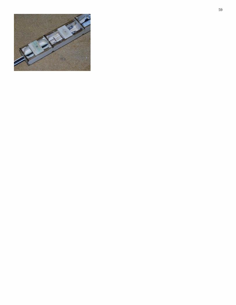
• Cut out a single block of 35x30x12mm balsa
• Butt glue the block to the rear of the fusulage (F5) above the control wire guide tubes
– Avoid getting glue on the guide tubes
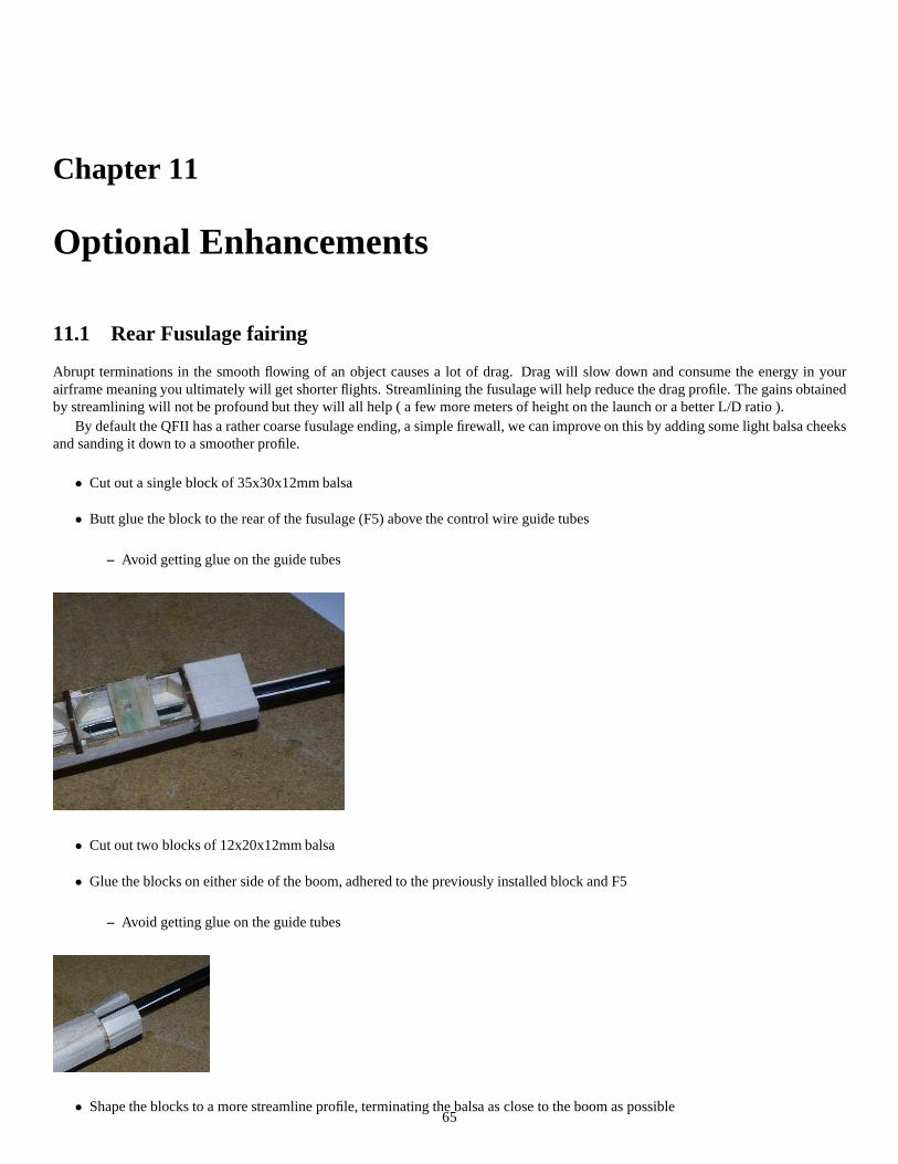
• Cut out two blocks of 12x20x12mm balsa
• Glue the blocks on either side of the boom, adhered to the previously installed block and F5
– Avoid getting glue on the guide tubes
• Shape the blocks to a more streamline profile, terminating the balsa as close to the boom as possible65
66 CHAPTER 11. OPTIONAL ENHANCEMENTS
11.2 Fiberglassing
If you wish to add some additional durability to the QFII, youcan apply fiberglass to the fusulage allowing it to handle landingson rougher ground (for those moments when a hand catch just doesn’t seem to work). An additional advantage of using FG on thefusulage is that it adds strength to the whole assembly whichcan allow you to shape the fusulage more curvatiously hence improving itsstreamlining.
The exact method for fiberglassing the fusulage will vary depending on your experience and type of glass that you’re working with.We will be using 2oz straight weave cloth and bond it with clear water based polyureathane paint (Cabots, Minwax etc). Thenice
thing about using PU paint is that it’s low cost compared to resin or epoxy and it isn’t as toxic, additionally it doesn’t require mixingother than the usual stirring before use hence there’s no excess wastage.
11.2.1 Fusulage Glassing
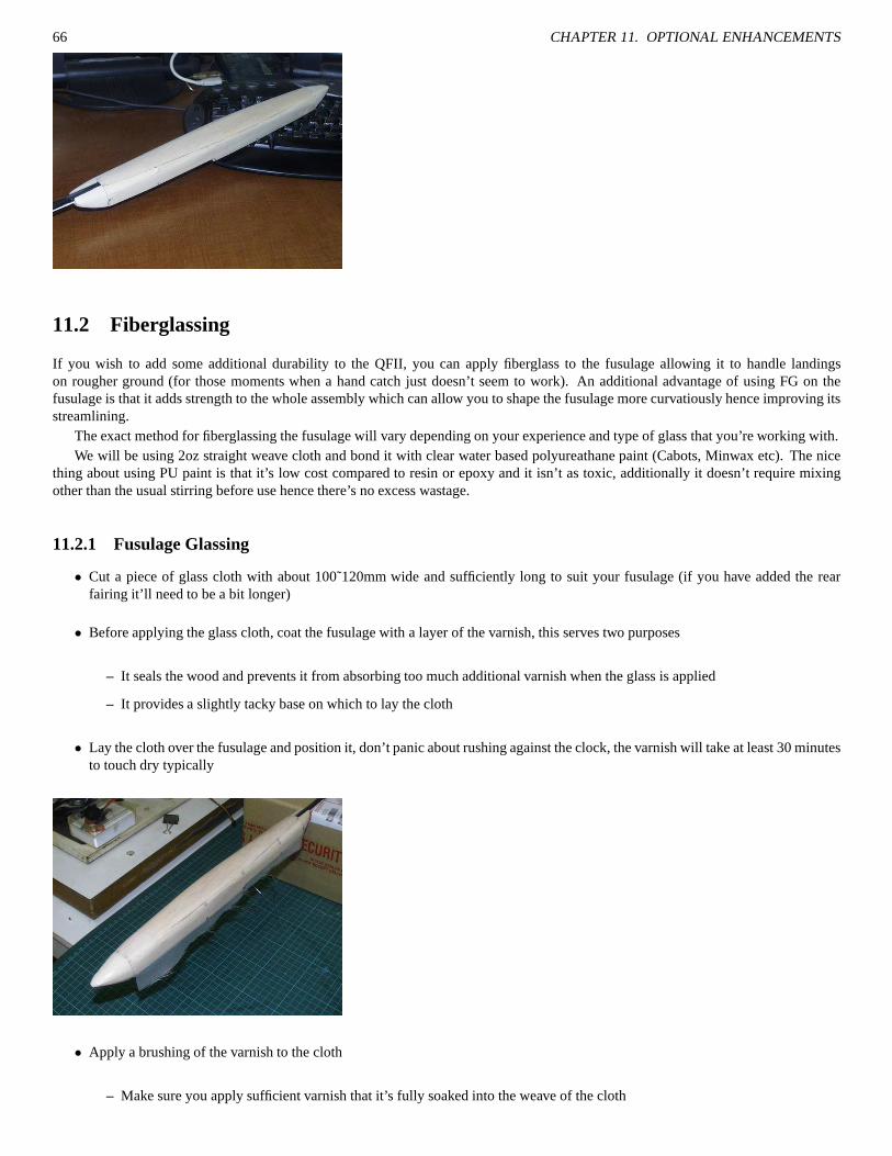
• Cut a piece of glass cloth with about 100˜120mm wide and sufficiently long to suit your fusulage (if you have added the rearfairing it’ll need to be a bit longer)
• Before applying the glass cloth, coat the fusulage with a layer of the varnish, this serves two purposes
– It seals the wood and prevents it from absorbing too much additional varnish when the glass is applied
– It provides a slightly tacky base on which to lay the cloth
• Lay the cloth over the fusulage and position it, don’t panic about rushing against the clock, the varnish will take at least 30 minutesto touch dry typically
• Apply a brushing of the varnish to the cloth
– Make sure you apply sufficient varnish that it’s fully soakedinto the weave of the cloth

11.2. FIBERGLASSING 67
• After the first coat has dried partially (approximately 3 hours for a lot of varnishes) cut off the excess cloth using a sharp No.11blade
• You will need to apply about three (3) coats of varnish beforethe weave of the cloth seals up.
11.2.2 Canopy Glassing
To make the glassing of the canopy easier, we do it separatelyto the fusulage
• Tack glue the canopy to a length of wood
• Clamp the extention to the bench, leaving the canopy to standclear of obstructions
• As with the fusulage, preseal the balsa with a quick coat of varnish
• Apply glass cloth

68 CHAPTER 11. OPTIONAL ENHANCEMENTS
• Apply first coat to glass
• Trim glass back when suitably dry
• Apply additional two layers of varnish
Chapter 12
Final Assembly
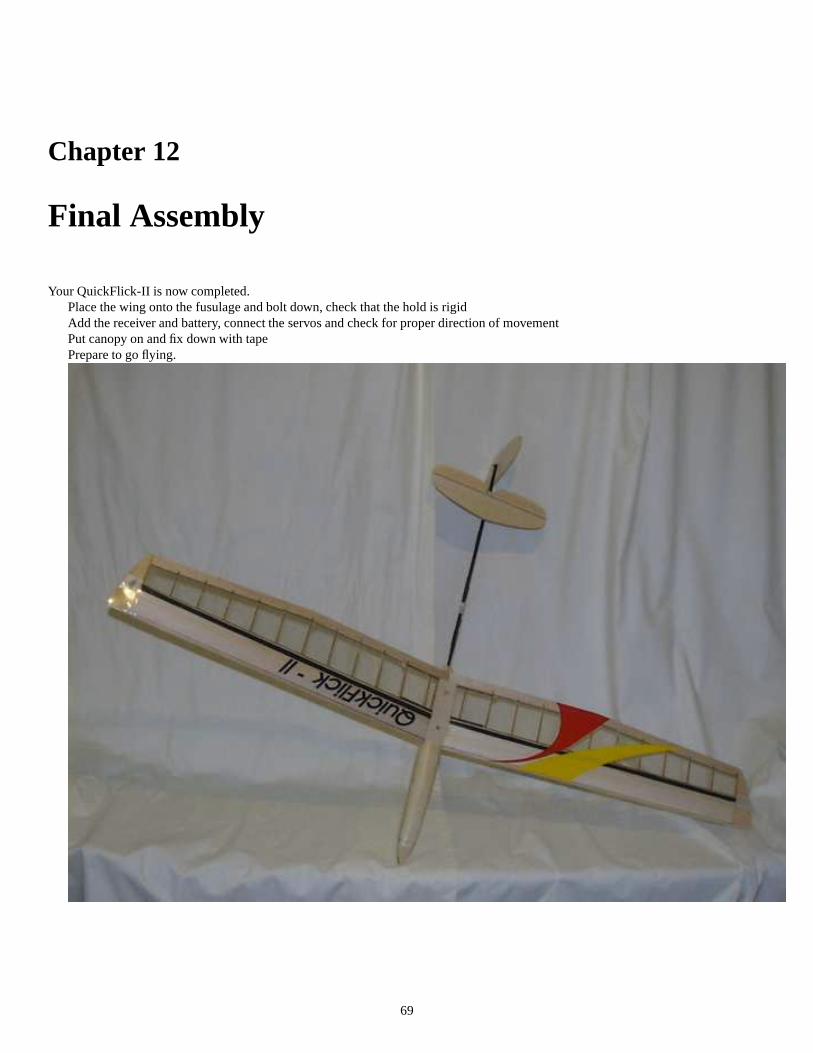
Your QuickFlick-II is now completed.Place the wing onto the fusulage and bolt down, check that thehold is rigidAdd the receiver and battery, connect the servos and check for proper direction of movementPut canopy on and fix down with tapePrepare to go flying.
69

70 CHAPTER 12. FINAL ASSEMBLY

Chapter 13
Flying
71

72 CHAPTER 13. FLYING

Chapter 14
Appendix
14.1 Making support tubes / sheaths
14.2 Common product names
• METHYLATED SPIRITS, also known as denatured alcohol or metho. Methylated spirits is a mixture of ethyl alcohol (95%) andmethyl alcohol (%5). The methyl alcohol is poisonous and is added to prevent the methylated spirits being used as cheap drinkingalcohol. We use metho as a thinning agent for epoxy.
• CYANOCYLOCRATE, also known as CA, SuperGlue and CrazyGlue.
• CARBON FIBER TOW, also known as lose ribbon or strand. CF Tow usually consistsof several thousand raw CF strands wrappedtogether in a ribbon/tow, from this product most CF productsare made, such as booms, cloth and even propellers.
• LAMINATING FILM , also known as Doculam. Laminating film of 1500 microns thickness is commonly used for covering smallplanes. The film is typically supplied on rolls in 300˜400mm widths with a length of 100˜200m. The film has two distinct sides, asmooth outer surface and a matt, slightly rough inner surface which is covered with the adhesive material. Off the roll laminatingfilm has a slightly opaque appearance. When heated the adhesive material converts and becomes translucent. Laminating film isvery tough for its thickness and can handle a lot of heat without suffering burn-through.
• POLYUREATHANE/ACRYLIC VARNISH, also referred to as “Minwax Polycrylic” to a lot of modellers. This paint is used as areplacement for resin when fiberglassing. While it does not posess the strength or rigidity of resin it is a suitable replacement forareas such as covering surfaces for the sake of impact resistance and surface durability. Each paint manufacturer will have theirown particular product namings, the key is to look for “waterwash-up”, “polyureathane” or “acrylic” stains and varnishes. InAustralia/NewZealand a common one is Cabots Crystal Clear.
14.3 Conversions
14.3.1 Lengths and sizes
Please note these values are approximations only.Metric Length Imperial
0.8mm 1/32”1.5mm 1/16”2.4mm 3/32”3.2mm 1/8”4.8mm 3/16”6.0mm 1/4”12.0mm 1/2”1270mm 50”
14.3.2 Weights
Please note these values are approximations only.73

74 CHAPTER 14. APPENDIX
Metric weight Imperial
28.35g 1oz220g 7.75oz454g 1lb
14.4 Further information

Index
Carbon Fiber, 43crossbeam, 46
Dihedral, 41dihedral, 33
fairing, 65Fiberglassing, 66
gussetts, 40
launch peg, 63Leading edge, 39
saddle, 46
tow, 43
webbing, 32, 39wing bolt, 44Wingtips, 39
75


