1 Distributed Embedded System Architecture Philip Koopman [email protected]July 12, 2002 & Electrical Computer ENGINEERING Institute for Complex Engineered Systems MPSOC 2002 My Perspective On (Distributed) Embedded Systems
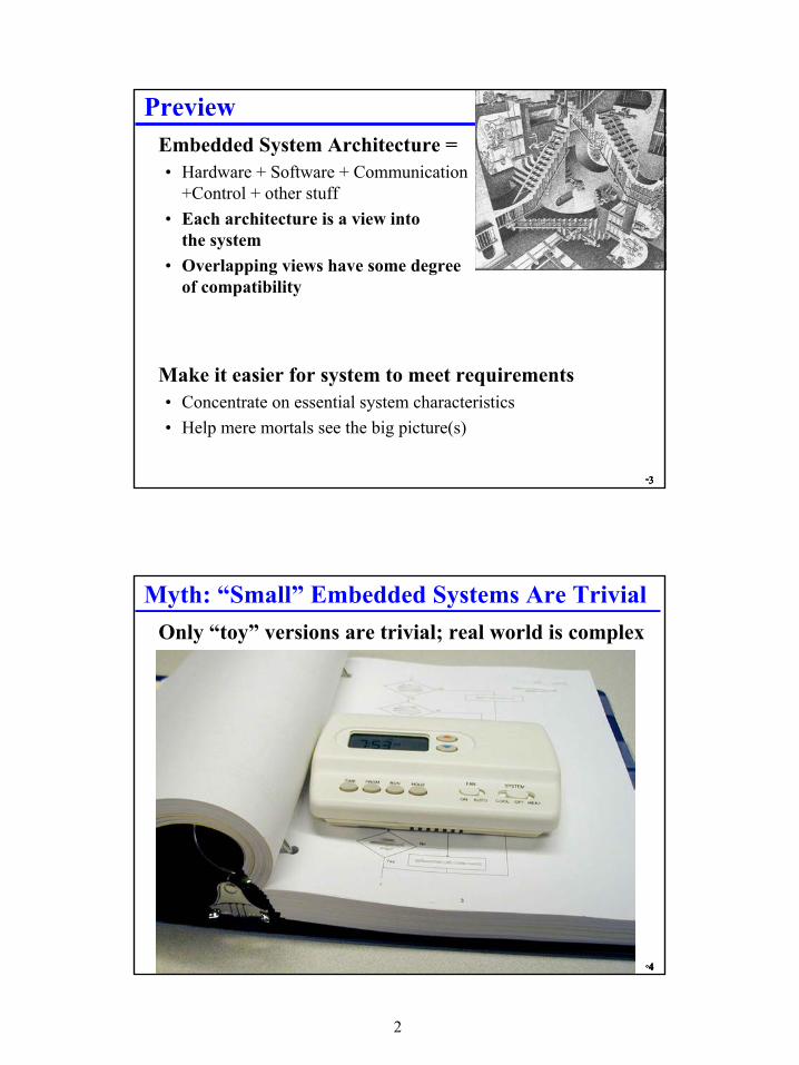
• Hardware + Software + Communication+Control + other stuff
• Each architecture is a view intothe system
• Overlapping views have some degreeof compatibility
� Make it easier for system to meet requirements• Concentrate on essential system characteristics• Help mere mortals see the big picture(s)
°4°4°4°4
Myth: “Small” Embedded Systems Are Trivial� Only “toy” versions are trivial; real world is complex
3
°5°5°5°5
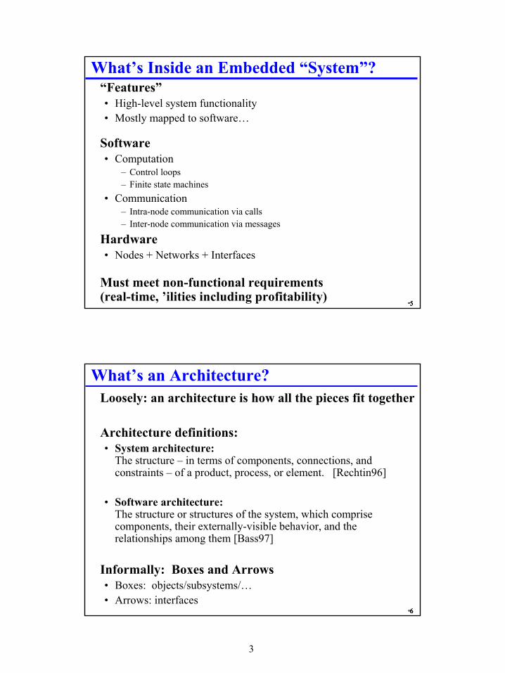
What’s Inside an Embedded “System”?� “Features”
• High-level system functionality• Mostly mapped to software…
� Software• Computation
– Control loops– Finite state machines
• Communication– Intra-node communication via calls– Inter-node communication via messages
� Hardware• Nodes + Networks + Interfaces
� Must meet non-functional requirements(real-time, ’ilities including profitability)
°6°6°6°6
What’s an Architecture?� Loosely: an architecture is how all the pieces fit together
� Architecture definitions:• System architecture:
The structure – in terms of components, connections, and constraints – of a product, process, or element. [Rechtin96]
• Software architecture:The structure or structures of the system, which comprise components, their externally-visible behavior, and the relationships among them [Bass97]
� Informally: Boxes and Arrows• Boxes: objects/subsystems/…• Arrows: interfaces
4
°7°7°7°7
My Definition Of An Architecture� An architecture is an organized collection of components
that describes:• both behaviors and interactions
» (boxes & arrows)
• with respect to a specific abstraction approach and» (rule for when to create a set of subsystem boxes)
• subject to a set of goals+constraints» (rules to evaluate how good the architecture is)
• An implementation uses a specific mechanism to create a behavior and and interface for a component (it’s an instantiation of an architecture)
� One person’s component is another person’s system• An implementation can have multiple components, each with its
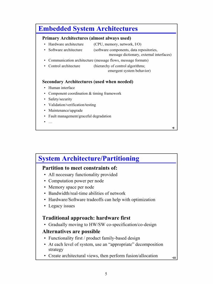
message dictionary, external interfaces)• Communication architecture (message flows, message formats)• Control architecture (hierarchy of control algorithms;
emergent system behavior)
� Secondary Architectures (used when needed)• Human interface• Component coordination & timing framework• Safety/security• Validation/verification/testing• Maintenance/upgrade• Fault management/graceful degradation• …
°10°10°10°10
System Architecture/Partitioning� Partition to meet constraints of:
• All necessary functionality provided• Computation power per node• Memory space per node• Bandwidth/real-time abilities of network• Hardware/Software tradeoffs can help with optimization• Legacy issues
� Traditional approach: hardware first• Gradually moving to HW/SW co-specification/co-design
� Alternatives are possible• Functionality first / product family-based design• At each level of system, use an “appropriate” decomposition
strategy• Create architectural views, then perform fusion/allocation
6
°11°11°11°11
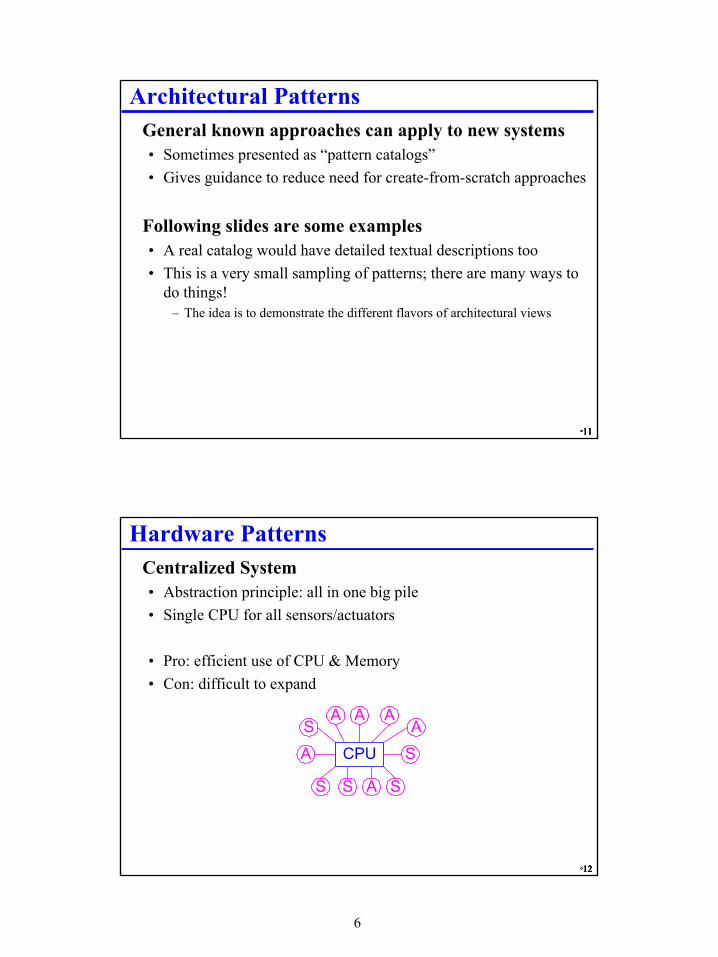
Architectural Patterns� General known approaches can apply to new systems
• Sometimes presented as “pattern catalogs”• Gives guidance to reduce need for create-from-scratch approaches
� Following slides are some examples• A real catalog would have detailed textual descriptions too• This is a very small sampling of patterns; there are many ways to
do things!– The idea is to demonstrate the different flavors of architectural views
°12°12°12°12
Hardware Patterns� Centralized System
• Abstraction principle: all in one big pile• Single CPU for all sensors/actuators
• Pro: efficient use of CPU & Memory• Con: difficult to expand
ASA
S
CPU
S A S
AA
A
S
7
°13°13°13°13
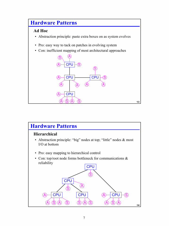
Hardware Patterns� Ad Hoc
• Abstraction principle: paste extra boxes on as system evolves
• Pro: easy way to tack on patches in evolving system• Con: inefficient mapping of most architectural approaches
CPU
A S A S
CPU
S A
A
A S
CPU
AA
A CPU
S
AA
S
°14°14°14°14
Hardware Patterns� Hierarchical
• Abstraction principle: “big” nodes at top; “little” nodes & mostI/O at bottom
• Pro: easy mapping to hierarchical control• Con: top/root node forms bottleneck for communications &
reliability
CPU
A S A S
CPU
S A S
CPU
S A
A
A
A S
CPU
CPU
S
SA
8
°15°15°15°15
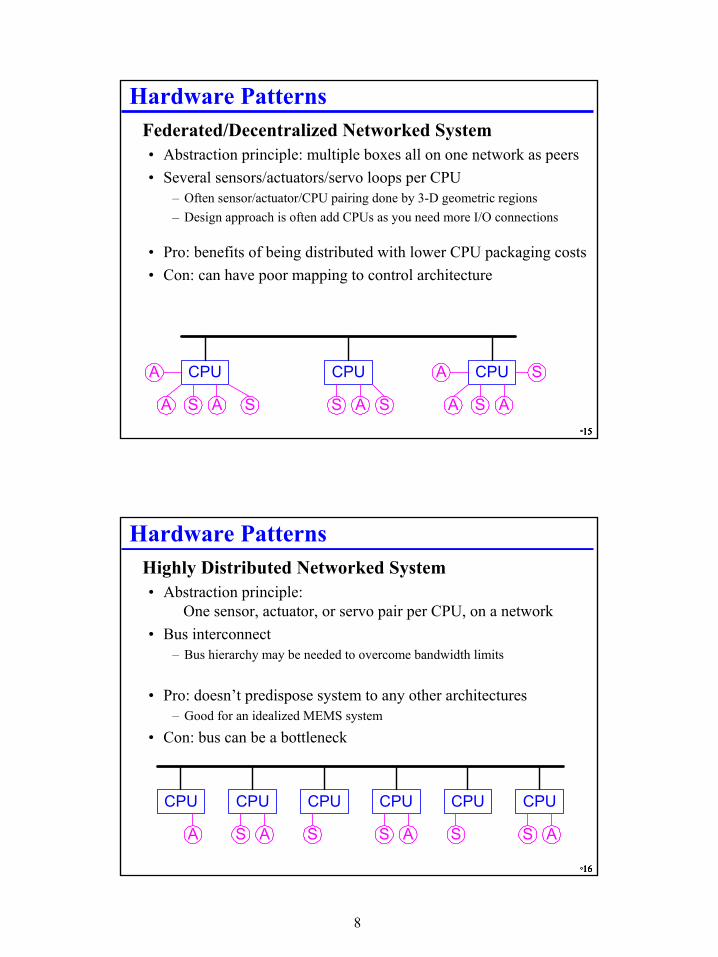
Hardware Patterns� Federated/Decentralized Networked System
• Abstraction principle: multiple boxes all on one network as peers• Several sensors/actuators/servo loops per CPU
– Often sensor/actuator/CPU pairing done by 3-D geometric regions– Design approach is often add CPUs as you need more I/O connections
• Pro: benefits of being distributed with lower CPU packaging costs• Con: can have poor mapping to control architecture
CPU
A S A S
CPU
S A S
CPU
S A
A
A
A S
°16°16°16°16
Hardware Patterns� Highly Distributed Networked System
• Abstraction principle:One sensor, actuator, or servo pair per CPU, on a network
• Bus interconnect– Bus hierarchy may be needed to overcome bandwidth limits
• Pro: doesn’t predispose system to any other architectures– Good for an idealized MEMS system
• Con: bus can be a bottleneck
CPU CPU CPU
A S A S
CPU
S A
CPU
S
CPU
S A
9
°17°17°17°17
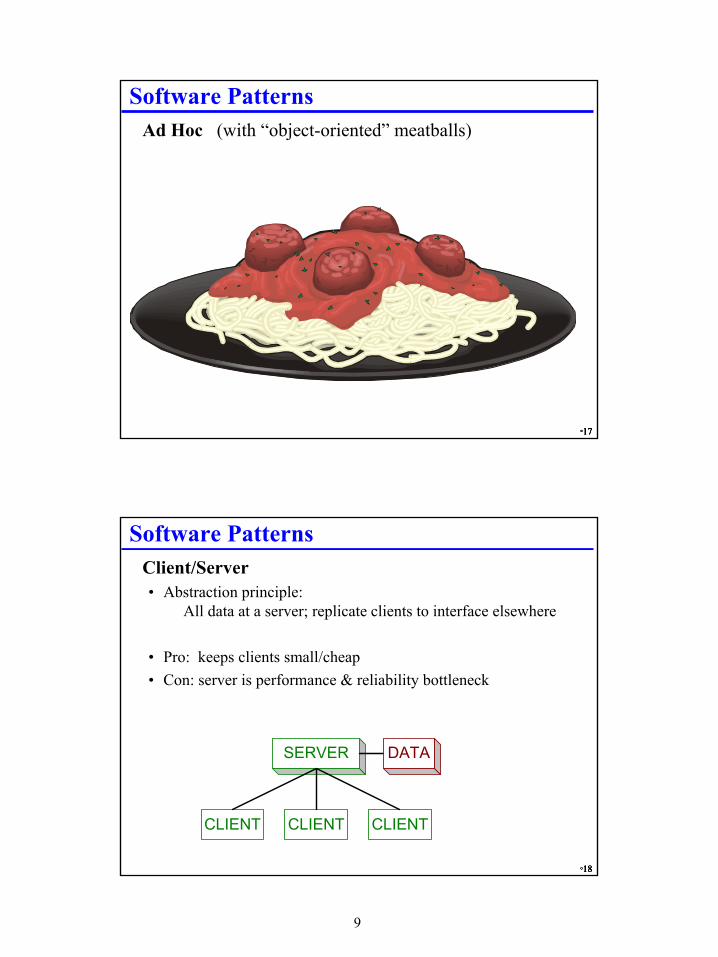
Software Patterns� Ad Hoc (with “object-oriented” meatballs)
°18°18°18°18
Software Patterns� Client/Server
• Abstraction principle:All data at a server; replicate clients to interface elsewhere
• Pro: keeps clients small/cheap• Con: server is performance & reliability bottleneck
SERVER
CLIENT CLIENT CLIENT
DATA
10
°19°19°19°19
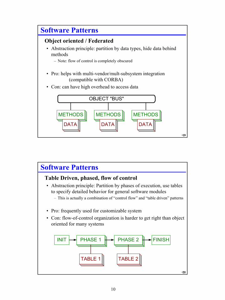
Software Patterns� Object oriented / Federated
• Abstraction principle: partition by data types, hide data behindmethods
– Note: flow of control is completely obscured
• Pro: helps with multi-vendor/mult-subsystem integration(compatible with CORBA)
• Con: can have high overhead to access data
METHODS
DATA
OBJECT "BUS"
METHODS
DATA
METHODS
DATA
°20°20°20°20
Software Patterns� Table Driven, phased, flow of control
• Abstraction principle: Partition by phases of execution, use tables to specify detailed behavior for general software modules
– This is actually a combination of “control flow” and “table driven” patterns
• Pro: frequently used for customizable system• Con: flow-of-control organization is harder to get right than object
oriented for many systems
PHASE 1
TABLE 1
PHASE 2
TABLE 2
INIT FINISH
11
°21°21°21°21
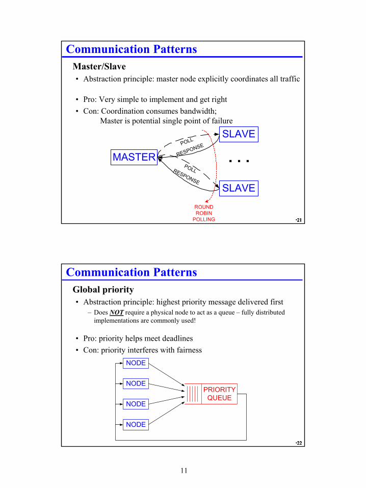
Communication Patterns� Master/Slave
• Abstraction principle: master node explicitly coordinates all traffic
• Pro: Very simple to implement and get right• Con: Coordination consumes bandwidth;
Master is potential single point of failure
SLAVE
MASTERPOLL
RESPONSE
SLAVE
POLLRESPONSE
. . .
ROUNDROBIN
POLLING
°22°22°22°22
Communication Patterns� Global priority
• Abstraction principle: highest priority message delivered first– Does NOT require a physical node to act as a queue – fully distributed
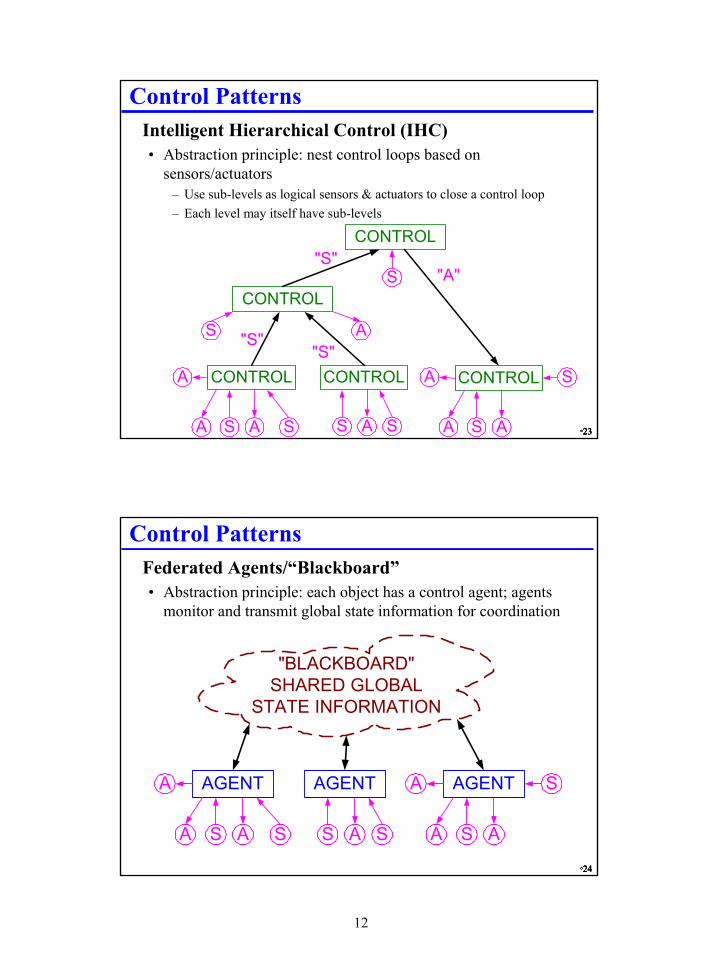
Control Patterns� Intelligent Hierarchical Control (IHC)
• Abstraction principle: nest control loops based on sensors/actuators
– Use sub-levels as logical sensors & actuators to close a control loop– Each level may itself have sub-levels
CONTROL
A S A S
CONTROL
S A S
CONTROL
S A
A
A
A S
CONTROL
CONTROL
S
S A
"S""A"
"S""S"
°24°24°24°24
Control Patterns� Federated Agents/“Blackboard”
• Abstraction principle: each object has a control agent; agents monitor and transmit global state information for coordination
AGENT
A S A S
AGENT
S A S
AGENT
S A
A
A
A S
"BLACKBOARD"SHARED GLOBAL
STATE INFORMATION
13
°25°25°25°25
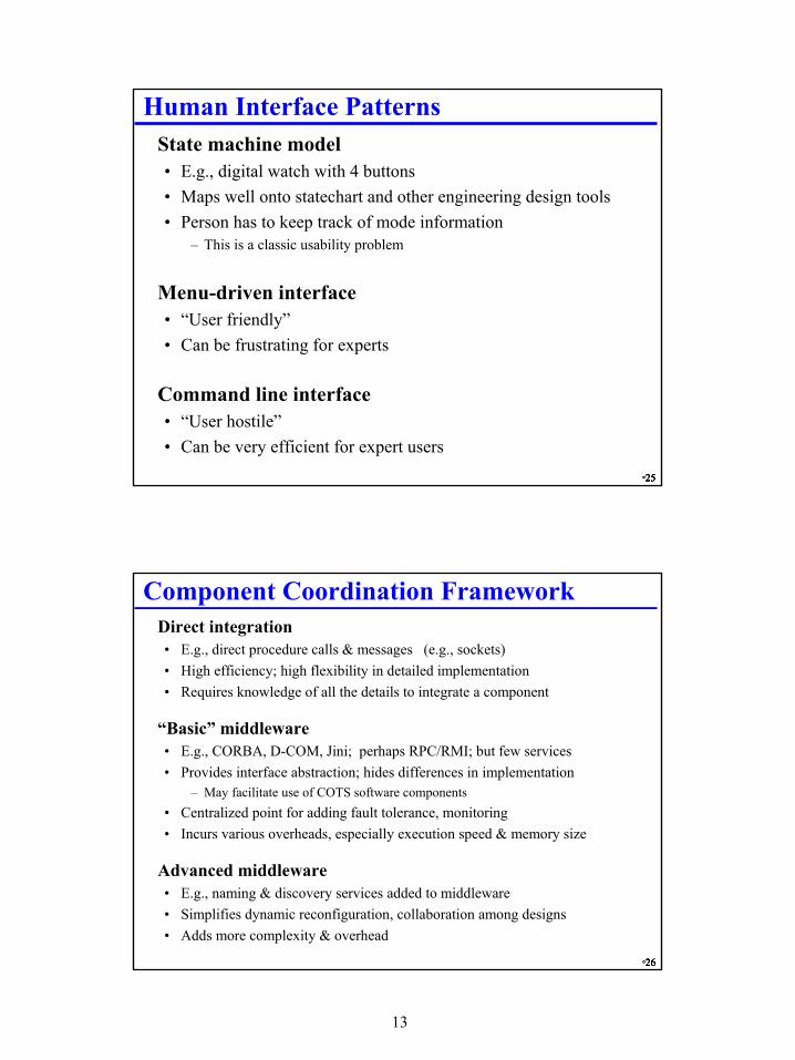
Human Interface Patterns� State machine model
• E.g., digital watch with 4 buttons• Maps well onto statechart and other engineering design tools• Person has to keep track of mode information
– This is a classic usability problem
� Menu-driven interface• “User friendly”• Can be frustrating for experts
� Command line interface• “User hostile”• Can be very efficient for expert users
°26°26°26°26
Component Coordination Framework� Direct integration
• E.g., direct procedure calls & messages (e.g., sockets)• High efficiency; high flexibility in detailed implementation• Requires knowledge of all the details to integrate a component
� “Basic” middleware• E.g., CORBA, D-COM, Jini; perhaps RPC/RMI; but few services• Provides interface abstraction; hides differences in implementation
– May facilitate use of COTS software components• Centralized point for adding fault tolerance, monitoring• Incurs various overheads, especially execution speed & memory size
� Advanced middleware• E.g., naming & discovery services added to middleware• Simplifies dynamic reconfiguration, collaboration among designs• Adds more complexity & overhead
14
°27°27°27°27
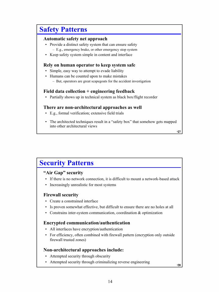
Safety Patterns� Automatic safety net approach
• Provide a distinct safety system that can ensure safety– E.g., emergency brake, or other emergency stop system
• Keep safety system simple in content and interface
� Rely on human operator to keep system safe• Simple, easy way to attempt to evade liability• Humans can be counted upon to make mistakes
– But, operators are great scapegoats for the accident investigation
� Field data collection + engineering feedback• Partially shows up in technical system as black box/flight recorder
� There are non-architectural approaches as well• E.g., formal verification; extensive field trials
• The architected techniques result in a “safety box” that somehow gets mapped into other architectural views
°28°28°28°28
Security Patterns� “Air Gap” security
• If there is no network connection, it is difficult to mount a network-based attack• Increasingly unrealistic for most systems
� Firewall security• Create a constrained interface• Is proven somewhat effective, but difficult to ensure there are no holes at all• Constrains inter-system communication, coordination & optimization
� Encrypted communication/authentication• All interfaces have encryption/authentication• For efficiency, often combined with firewall pattern (encryption only outside
firewall trusted zones)
� Non-architectural approaches include: • Attempted security through obscurity• Attempted security through criminalizing reverse engineering
15
°29°29°29°29
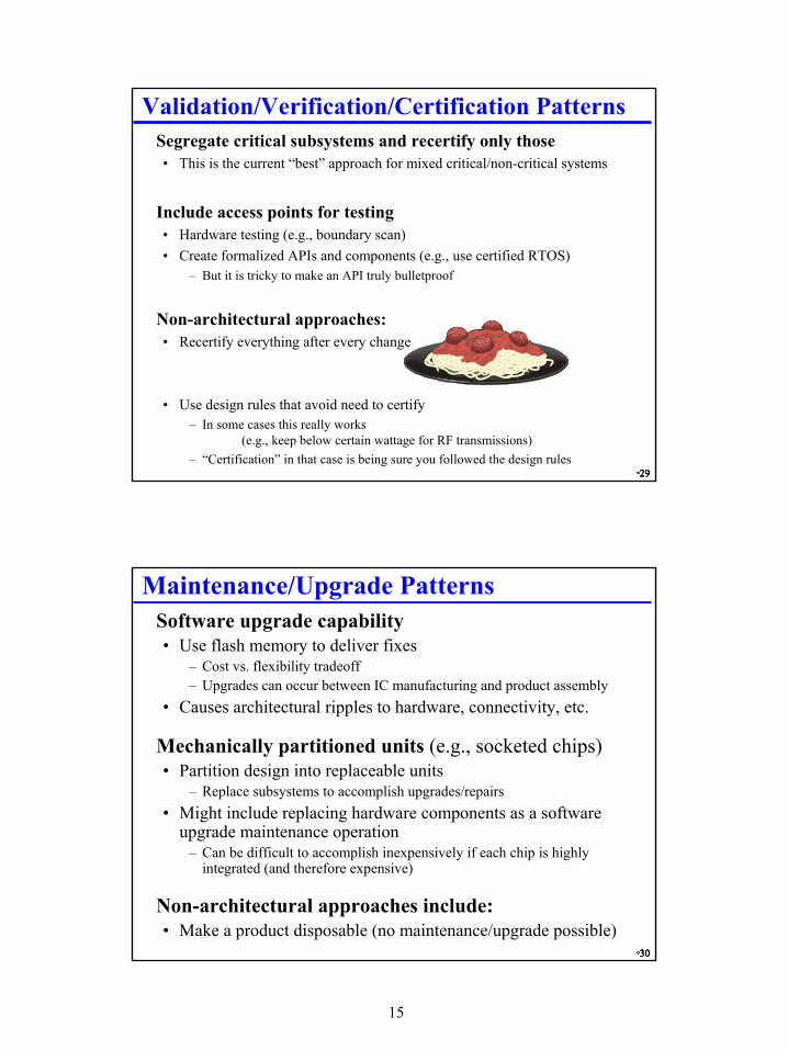
Validation/Verification/Certification Patterns� Segregate critical subsystems and recertify only those
• This is the current “best” approach for mixed critical/non-critical systems
� Include access points for testing• Hardware testing (e.g., boundary scan)• Create formalized APIs and components (e.g., use certified RTOS)
– But it is tricky to make an API truly bulletproof
� Non-architectural approaches:• Recertify everything after every change
• Use design rules that avoid need to certify– In some cases this really works
(e.g., keep below certain wattage for RF transmissions)– “Certification” in that case is being sure you followed the design rules
• Use flash memory to deliver fixes– Cost vs. flexibility tradeoff– Upgrades can occur between IC manufacturing and product assembly
• Causes architectural ripples to hardware, connectivity, etc.
� Mechanically partitioned units (e.g., socketed chips)• Partition design into replaceable units
– Replace subsystems to accomplish upgrades/repairs• Might include replacing hardware components as a software
upgrade maintenance operation– Can be difficult to accomplish inexpensively if each chip is highly
integrated (and therefore expensive)
� Non-architectural approaches include:• Make a product disposable (no maintenance/upgrade possible)
16
°31°31°31°31
Fault Tolerance/Degradation Patterns� Replication with failover
• Every critical function has at least one backup– Active replication with hot standby failover– Passive replication with cold standby + transaction logs for catching up– Spare resource pool with reboot after reconfiguration
• Works well if failures are random (not all software defects are random!)• Aggressive replication is expensive
� Function/load shedding as replicants fail• Architecturally, this shows up as a configuration or workload manager• Spread workload over replicated units
– As units fail, capacity is reduced, but each unit can operate standalone if needed• Have configuration plans that map functions to units
– As units fail, different mappings are used to keep key functions running
°32°32°32°32
Multi-View Architectural Fusion� Every real system has several architectural views
• Differing views have to be combined to form “The Architecture”• This process is a generalization of allocating software modules to
hardware, but can have much higher dimensionality
� Most times you can use any architectural combination• But, you/your design may suffer significantly if you pick poorly
CPU
A S A S
CPU
S A
A
A S
CPU
AA
A CPU
S
AA
S
CONTROL
A S A S
CONTROL
S A S
CONTROL
S A
A
A
A S
CONTROL
CONTROL
S
S A
"S""A"
"S""S"
Point-to-Point Hardware Hierarchical Control
17
°33°33°33°33
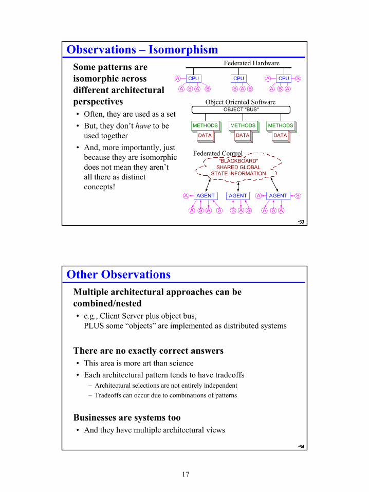
Observations – Isomorphism� Some patterns are
isomorphic across different architectural perspectives• Often, they are used as a set• But, they don’t have to be
used together• And, more importantly, just
because they are isomorphic does not mean they aren’t all there as distinct concepts!
CPU
A S A S
CPU
S A S
CPU
S A
A
A
A S
METHODS
DATA
OBJECT "BUS"
METHODS
DATA
METHODS
DATA
AGENT
A S A S
AGENT
S A S
AGENT
S A
A
A
A S
"BLACKBOARD"SHARED GLOBAL
STATE INFORMATION
Federated Hardware
Object Oriented Software
Federated Control
°34°34°34°34
Other Observations� Multiple architectural approaches can be
combined/nested• e.g., Client Server plus object bus,
PLUS some “objects” are implemented as distributed systems
� There are no exactly correct answers• This area is more art than science• Each architectural pattern tends to have tradeoffs
– Architectural selections are not entirely independent– Tradeoffs can occur due to combinations of patterns
� Businesses are systems too• And they have multiple architectural views
18
°35°35°35°35
Non-Architectural Approaches� Where do all those “non-architectural” approaches fit?
• Typically they are things that don’t trace to specific boxes in any architecture• Sometimes they are omissions
– e.g., “we don’t have a security strategy”• Sometimes they trace to non-engineering business architecture boxes
– e.g., information access architecture uses an NDA in support of “security through obscurity”
• Sometimes they trace to a business model– e.g., “we want consumers to upgrade by throwing the old one away”
» Thus, make products non-repairable, but cheaper than repairable ones» Perhaps it consumers encounter a bug, tell them their unit has worn out and they need to
buy another one to replace it (one that will have newer software…)
� Most “systems” are really “systems of systems”• Some high level functions get diffused into emergent properties within
components (this is a traceability problem)• Some high level constraints get converted into boxes within components• …
°36°36°36°36
How To Create A Functional ArchitectureNote: this is a combined view, 1-D approach to architecture� Functional Architecture = subsystems created by splitting
“functions” • Classical large system development technique• Seldom optimal, but most engineers can be trained to think this way• Historically the architecture of choice for weapon systems• Single, combined view of hardware + software + control, with implied
federated communication architecture (1 “box” = 1 “subsystem”)
� Architectural methodology (a guide to “Functional Boxology”)• List primary mission goals
– Associate secondary mission goals• List verbs that correspond to “marketing requirements”
– One verb per requirement– Be sure that verbs are orthogonal
• Architectural decomposition is one box per verb– Recurse as necessary– Stop recursing when each box is a design team of 4 people or fewer
19
°37°37°37°37
Elevator Functional Architecture
PrimaryMission
SecondaryMissions
Provide safe, timely, comfortablepassage between floors.
DeliverPassengers
Quickly
InformUsers
Conform ToBuildingCodes
ProtectPassengers
SupportCustomized
Behavior
Example Functional Architecture for Elevator
ProvideTranquil
Environment
SupportMaintenance
MOVE
ENSURESAFETY
CONTROLACCESS
INFORM USERS
DISPATCH
DETERMINEPASSENGER
INTENT
SET MODES
TOP-LEVEL FUNCTIONS
CONTROLACCESS
CONTROLCAR ACCESS
CONTROLHOISTWAY
ACCESS
DEAL WITHDOOR
OBSTRUCTIONS
LOAD
CLOSE
REOPENFOR
LOADING
REOPENFOR
UNLOADING
UNLOAD
OPENHOISTWAY FORMAINTENANCE
REVERSEDOOR
SET DWELLTIME
PROVIDEPASSENGERPROMPTING
DISPLAYDESTINATIONFOR LOADING
DISPLAYFLOOR FORUNLOADING
SET MODES
UP-PEAK
DOWN-PEAK
"NORMAL"
FIRERECALL
FIREOPERATION
20
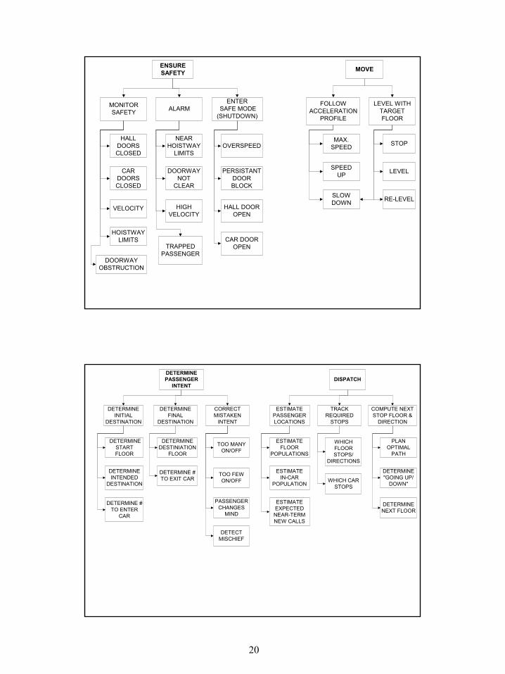
ENSURESAFETY
MONITORSAFETY ALARM
ENTER SAFE MODE(SHUTDOWN)
HALLDOORSCLOSED
VELOCITY
HOISTWAYLIMITS
DOORWAYOBSTRUCTION
CARDOORSCLOSED
NEARHOISTWAY
LIMITS
DOORWAYNOT
CLEAR
OVERSPEED
HIGHVELOCITY
PERSISTANTDOORBLOCK
HALL DOOROPEN
CAR DOOROPENTRAPPED
PASSENGER
MOVE
FOLLOWACCELERATION
PROFILE
LEVEL WITHTARGETFLOOR
SPEEDUP
SLOWDOWN
STOP
LEVEL
RE-LEVEL
MAX.SPEED
DETERMINEPASSENGER
INTENT
DETERMINEINITIAL
DESTINATION
DETERMINEFINAL
DESTINATION
CORRECTMISTAKEN
INTENT
DETERMINESTARTFLOOR
DETERMINE #TO ENTER
CAR
DETERMINEINTENDED
DESTINATION
TOO MANYON/OFF
TOO FEWON/OFF
DETERMINEDESTINIATION
FLOOR
DETERMINE #TO EXIT CAR
PASSENGERCHANGES
MIND
DETECTMISCHIEF
DISPATCH
ESTIMATEPASSENGERLOCATIONS
TRACKREQUIRED
STOPS
COMPUTE NEXTSTOP FLOOR &
DIRECTION
ESTIMATEFLOOR
POPULATIONS
ESTIMATEEXPECTEDNEAR-TERMNEW CALLS
ESTIMATEIN-CAR
POPULATION
PLANOPTIMAL
PATH
DETERMINE"GOING UP/
DOWN"
WHICHFLOORSTOPS/
DIRECTIONS
WHICH CARSTOPS
DETERMINENEXT FLOOR
21
INFORM USERS
INFORMPASSENGERS
INFORMBUILDING
MANAGERS
INFORMMAINTAINERS
ESTIMATETIME TO CAR
ARRIVAL
ESTIMATETIME LEFT TO
RIDE
REASSUREPASSENGERPICKUP WILL
HAPPEN
DISPLAYEFFICIENCY
DISPLAYOPERATIONAL
STATUS
PROVIDEINFORMATIONFOR OTHER
BUILDINGSUBSYSTEMS
DIAGNOSIS
PROGNOSIS
SELF-TEST
REASSUREPASSENGER
DROPOFFWILL HAPPEN
TIME FORPERIODIC
MAINTENANCE
CONTROLACCESS
CONTROLCAR ACCESS
CONTROLHOISTWAY
ACCESS
DEAL WITHDOOR
OBSTRUCTIONS
LOAD
CLOSE
REOPENFOR
LOADING
REOPENFOR
UNLOADING
UNLOAD
OPENHOISTWAY FORMAINTENANCE
REVERSEDOOR
SET DWELLTIME
PROVIDEPASSENGERPROMPTING
DISPLAYDESTINATIONFOR LOADING
DISPLAYFLOOR FORUNLOADING
SET MODES
UP-PEAK
DOWN-PEAK
"NORMAL"
FIRERECALL
FIREOPERATION
22
°43°43°43°43
RoSES = Robust Self-configuring Embedded Systems� Research Context:
fine grain distributed embedded systems� Research vision:
Product families + auto-reconfiguration =• Operation with failed components• Automatic integration of inexact spares• Automatic integration of upgrades• Fine-grain product family capability
� Potential Impact:• Logical component interfaces + config mgr.• Fine-grain software component support• Architectures that are naturally resilient
� What we’re really learning is where all the difficult research issues are!
System Variables/Network
BaselineSensor SW
Functionality
Dynamic Interfaceto Object Bus
Basic S/ADevice
Smart Sensors/Actuators
LocalCPU &
Memory
Adapter RepositoryCUSTOMIZATION MANAGER
SWAdapter forHigh Level
LogicalInterface
SWCompute/Control
Functions
°44°44°44°44
Some Specification & Evaluation Research Issues• Allocating software to available components
– Problem: given fixed resources, how to you maximize utility?– What baseline set of components gives most reconfiguration flexibility?
• System specification– Product family architecture specification– Specification of utility for different features & feature sets– When/how to determine HW/SW/Mechanical/Business tradeoffs
• Evaluation– Is a system really “working” when it is partially disabled?– Safety/certification of component-based systems with many failure modes
• Design– Many real embedded systems have global modes that break design methods
» Do you do a distinct system design for each mode and merge?– Many real systems are hybrid discrete+continuous
• Implementation– Software runtime infrastructure (Jini was a poor fit to an embedded network)– Real time scheduling for distributed networked system– Security of embedded+enterprise combined system
23
°45°45°45°45
Big Open Issues� How do we know which architecture to use and when?
• Can we evaluate architectures for properties such as graceful degradation in the abstract?
• But, at least now we know that this is a decision to consider –there is more than just one possibility
� Can system architects be trained, or must they be born?• “Most really good architectures come from a single architect”• If functional architecture isn’t the best answer, what is?
– Or is good enough really good enough?
°46°46°46°46
Review� System Architecture via patterns for multiple system views
• Multiple views for most systems are essential– Hardware + Software + Communication + Control + others
• There is no “free lunch” – you probably have to choose between– Be constrained to a 1-D/low-D decomposition (e.g., functional architecture)
vs.– Deal with allocation incompatibilities when fusing a many-D decomposition
• Multiple architectures mean many different tradeoffs– System-level tradeoffs between mechanical, HW, SW, and other implementation
methods are common– Existence of non-architectural options mean some tradeoffs happen between
technical and business/non-technical system layers!
� Functional architecture: yes, there is a multi-view recipe!• But it usually produces mediocre system architectures• Doing better is a deep research topic