UNESCO-NIGERIA TECHNICA L & VOCATIO NAL EDUCATION REVITALISATION PROJECT-PHASE II YEAR 2- SE MESTER 2 THEORY/PRACTICAL Version 1: December 2008 NATIONAL DIPLOMA IN QUANTITY SURVEYING PRINCIPLES OF ENGINEERING MEASUREMENT COURSE CODE: QUS202
Transcript
UNESCO-NIGERIA TECHNICAL & VOCATIONAL EDUCATION REVITALISATION PROJECT-PHASE II
YEAR 2- SE MESTER 2
THEORY/PRACTICAL
Version 1: December 2008
NATIONAL DIPLOMA IN QUANTITY SURVEYING
PRINCIPLES OF ENGINEERING MEASUREMENT
COURSE CODE: QUS202
2
PRINCIPLES OF ENGINEERING MEASUREMENT TEACHING
MATERIALS
COURSE: PRINCIPLES OF ENGINEERING MEASUREMENT COURSE CODE: QUS 202
SECOND YEAR SECOND SEMESTER
PRESENTED BY
DEPARTMENT OF QUANTITY SURVEYING KADUNA POLYTECHNIC
KADUNA. TO
NATIONAL BOARD FOR TECHNICAL EDUCATION (NBTE) / UNESCO
NASIRU JIBRIN ABDULLHAKEM GARBA
VINCENT MARTINS (SNR)
DECEMBER 2008.
3
QUS 202 PRINCIPLES OF ENGINEERING MEASUREMENT TABLE OF CONTENT WEEK 1: 1.0 INTRODUCTION TO MEASUREMENT OF ELECTRICAL SERVICES
1.1 GENERAL BACKGROUND 1.2 MEASUREMENT PROCEDURES 1.3 INCOMING SERVICES UP TO BUT EXCLUDING MAIN
MEDIUM VOLTAGE SWICTH GEAR 1.4 LIGHTING INSTALLATION 1.5 ELECTRICAL HEATING INSTALLATION 1.6 LIGHTING PREVENTION SYSTEM 1.7 TRUNKING DUCTING CABLE TRAYS ASSOCIATED
WITH MORE THAN ONE INSTALLATION 1.8 PROCEDUR FOR THEMEASUREMENT OF
ELECTRICAL INSTALLATION 1.9 INCOMING SERVICES UP TO BUT EXCLUDING
SWTCH GEAR WEEK 2: 2.0 MEASUREMENT OF ELECTRICAL SERVICES ( TAKING OFF IN RESPECT OF ELECTRICAL SERVICES) 2.1 POWER INSTALLATION 2.2 LIGHTING INSTALLATION 2.3 ELECTRIC HEAT INSTALLATION 2.4 ELECTRICAL APPLIANCES 2.5 ELECTRICAL WORKS ASSOCIATED WITH 2.6 PLUMBUING AND MECHANICAL INSTALLATION WEEK 3: INTRODUCTION TO MEASUREMENT OF MECHANICAL/PLUMBING SERVICES 3.1 GENERAL BACKGROUND 3.2 MEASUREMENT PROCEDURES 3.3 APPROACH TO MEASUREMENT 3.4 WORK SECTIONS WEEK 4: TAKING OFF BILLING IN RESPECT OF MECHANICAL/PLUMBING SERVICES. 4.1 PIPE WORK GENERALLY 4.2 ADEQUACY OF MEASUREMENT 4.3 EQUIPMENT 4.4 AIR DUCTLINES 4.5 PIPEWORK AND DEDUCTION SUPPORT 4.6 BUILDER’S WORK IN CONNECTION WITH MECHANICAL
4
INSTALATION 4.7 EXTRACT FROM THE SPECIFICATION OF ENGINEERING WORKS FOR THE TREATMENT BLOCK WEEK 5: INTRODUCTION TO CIVIL ENGINEERING WORKS 5.1 EXCAVATION AND FILLING 5.2 CUT AND FILL CALCULATION WEEK 6: TAKING OFF IN RESPECT OF EXCAVATION AND FILLING.
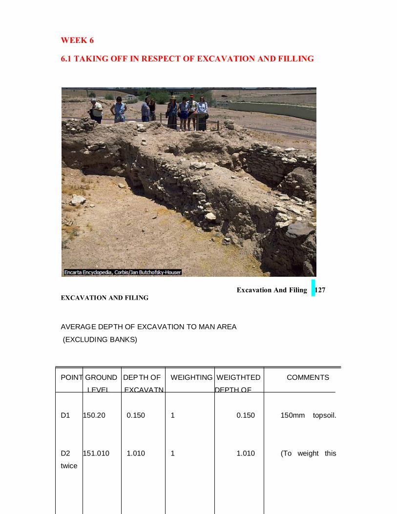
6.1 TAKING OFF IN RESPECT OF EXCAVATION AND FILLING
WEEK 7: STUDY DRAWINGS FOR MASS CONCRETE RETAINING WALL. 7.1 INTRODUCTION WEEK 8: TAKING OFF IN RESPECT OF MASS CONCRETE RETAINING WALL . WEEK 9: STUDY DRAWINGS AND TAKE OFF OF ESTATE ROADS. WEEK 10: TAKE OFF OF ESTATE ROAD CONTINUED. WEEK 11: TAKE OFF OF ESTATE ROAD CONTINUED WEEK 12: STUDY DRAWING AND BAR SCHEDULE OF PUMPING CHAMBER WEEK 13: TAKE OFF OF PUMPING CHAMBER WEEK 14: TAKE OFF OF PUMPING CHAMBER (CONTINUED) WEEK 15: TAKE OFF OF PUMPING CHAMBER (CONTINUED)
5
WEEK 1: 1.0 INTRODUCTION TO MEASURMEN T OF ELECTRICAL
ENGINEERING SERVICES
Fig 1
Construction
Walls Brick and concrete block throughout.
Floors Concrete with cement and sand screed
Roof Timber joisted flat construction
Height Finished floor to ceiling height – 2700mm
Specification
6
The following represents a brief specification to indicate the general requirements for the
installation but in order to price work in the commercial world a fully detailed specification
would be prepared and issued with the Bill. Such a detailed document is beyond the scope of
this book but referenced to a hypothetical full specification are made in some of the items in
the worked example where this would happen in practice.
Voltage 230volts 50Hz AC mains provided by public electricity authority
Enclosure Heavy gauged mild steel screwed conduit which acts as earth
continuity.
Cable PVC insulated single core cables drawn into conduit and clolour coded
as appropriate.
Lighting To be wired in two 5amp circuits in 1mm2 cables.
Power To be wired in two 30amp ring circuits in 2.5mm2 cables.
Water Heater To be wired in one 15amp radial circuit in 2.5mm2 cables.
Consumer Unit Surface type metal clad with 60amp main swich and 6 ways ( 5 per
distribution sheet and one spare way).
Main Cables To be wired in 10mm2 cables protected by short length of trunking
between meter and consumer unit.
Accessories Switches, ceiling roses and power outlets to be white plastic pattern.
Regulations The installations will comply with the latest IEE Regulations for
Electrical installations: Regulations for the Electrical Equipment of
Buildings.
7
Location Circuit
Remarks
Lighting Power Water Heater Points Switches Lamps Circ. no 13amp 13amp Circ.no 15amp Single Double Spur Type Nr One wayTwo way Nr Watts SSO SSO 1 Ceiling 2 2 2 60 3 2 2 Wall 2 2 150 2 Ceiling 1 1 1 100 4 1 5 1 2 Ceiling 1 1 1 100 4 2 6 2 2 6 1 4 1
Fig. 2
General Background
The measurement of electrical services poses many of the same problems as the measurement of mechanical services. In fact the two are often grouped together and referred to as ‘m and e services’ as a collective term. It is unusual, however, for the work to be carried out as separate contracts and to be designed by separate specialist engineers. It is quite common for the surveying duties within a quantity surveying or consulting engineer’s practice to be handled by separate specialist surveyors. There is a good deal of commonality in the approach to bill preparation.
A sound knowledge of electrical technology is required to understand the specification and to interpret the schematic drawings provided by the consulting engineer. A detailed knowledge of the lEE regulations for the electrical equipment of buildings and a knowledge of circuitry and wiring systems is essential so that trunking, tray and conduit runs can be plotted and the correct number of cables required measured for the two groups of services.
Measurement Procedures
The procedure for taking off electrical work is similar to that described for mechanical
services (chapter 8) and therefore has not been repeated. A sound, systematic and
logical approach with, possibly, the use of measurement schedules are the main
requirements.
Where circuits are to be measured in detail, such as circuits other than lighting and
small power, the route of the conduit and/or cable must be plotted on the plan or tracing
overlay and the number of cables indicated. This sketch will then form a record of what
is taken. An isometric sketch is often useful (as with pipework) to illustrate complex
Shop Toilet Store Totals
Circular Fluorescent
8
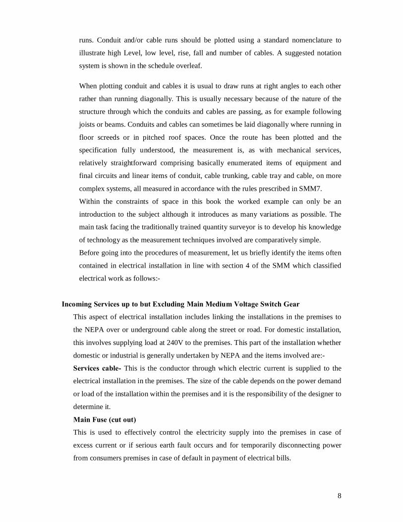
runs. Conduit and/or cable runs should be plotted using a standard nomenclature to
illustrate high Level, low level, rise, fall and number of cables. A suggested notation
system is shown in the schedule overleaf.
When plotting conduit and cables it is usual to draw runs at right angles to each other
rather than running diagonally. This is usually necessary because of the nature of the
structure through which the conduits and cables are passing, as for example following
joists or beams. Conduits and cables can sometimes be laid diagonally where running in
floor screeds or in pitched roof spaces. Once the route has been plotted and the
specification fully understood, the measurement is, as with mechanical services,
relatively straightforward comprising basically enumerated items of equipment and
final circuits and linear items of conduit, cable trunking, cable tray and cable, on more
complex systems, all measured in accordance with the rules prescribed in SMM7.
Within the constraints of space in this book the worked example can only be an
introduction to the subject although it introduces as many variations as possible. The
main task facing the traditionally trained quantity surveyor is to develop his knowledge
of technology as the measurement techniques involved are comparatively simple.
Before going into the procedures of measurement, let us briefly identify the items often
contained in electrical installation in line with section 4 of the SMM which classified
electrical work as follows:-
Incoming Services up to but Excluding Main Medium Voltage Switch Gear
This aspect of electrical installation includes linking the installations in the premises to
the NEPA over or underground cable along the street or road. For domestic installation,
this involves supplying load at 240V to the premises. This part of the installation whether
domestic or industrial is generally undertaken by NEPA and the items involved are:-
Services cable- This is the conductor through which electric current is supplied to the
electrical installation in the premises. The size of the cable depends on the power demand
or load of the installation within the premises and it is the responsibility of the designer to
determine it.
Main Fuse (cut out)
This is used to effectively control the electricity supply into the premises in case of
excess current or if serious earth fault occurs and for temporarily disconnecting power
from consumers premises in case of default in payment of electrical bills.
9
Meter
This measure the extent of power used by the consumer on the basic of which NEPA
prepares the consumer bills.
Statutorily, no person other than NEPA official is allowed to temper with the above stated
items which are generally referred to as NEPA installations
(1) Standby Equipment
Standby equipments are mostly installed to function only when the existing power source
fails or is shot down for maintenance or the like. Electricity generator set may only
function when NEPA supply is off. There may be two of such generators with each
working for a particular number of hours before the other takes off. An equipment such as
transformer could also be two with one working continuously while the other is only put
into use when the former has some fault. In most cases the standby equipments are
completely installed and are differently from items kept in the store which are generally
regarded as spares.
Mains Installation Excluding Final Subcircuit
The mains is a continuation of NEPA incoming upto and including a point where the first
distribution is made. Thus, in a small domestic installation with only consumer unit or
distribution board the mains is from the main switch upto and including the consumer unit or
distribution board.
But for large installation with medium voltage (M.V). Boards which supplies say six
distribution boards, the mains is from where the NEPA equipment stopped up to and include
the M.V board. The distance from the M.V board (excluding the M.V board) up to and
including the distribution boards are often referred to as submains. Hence for industrial or
large electrical installation the basic items often contained within the mains and submains
include:-
• High tension panel
• Transformers
• Medium voltage panels distribution boards
• Cables, cable tray, trunking or
• Busbas trunking
10
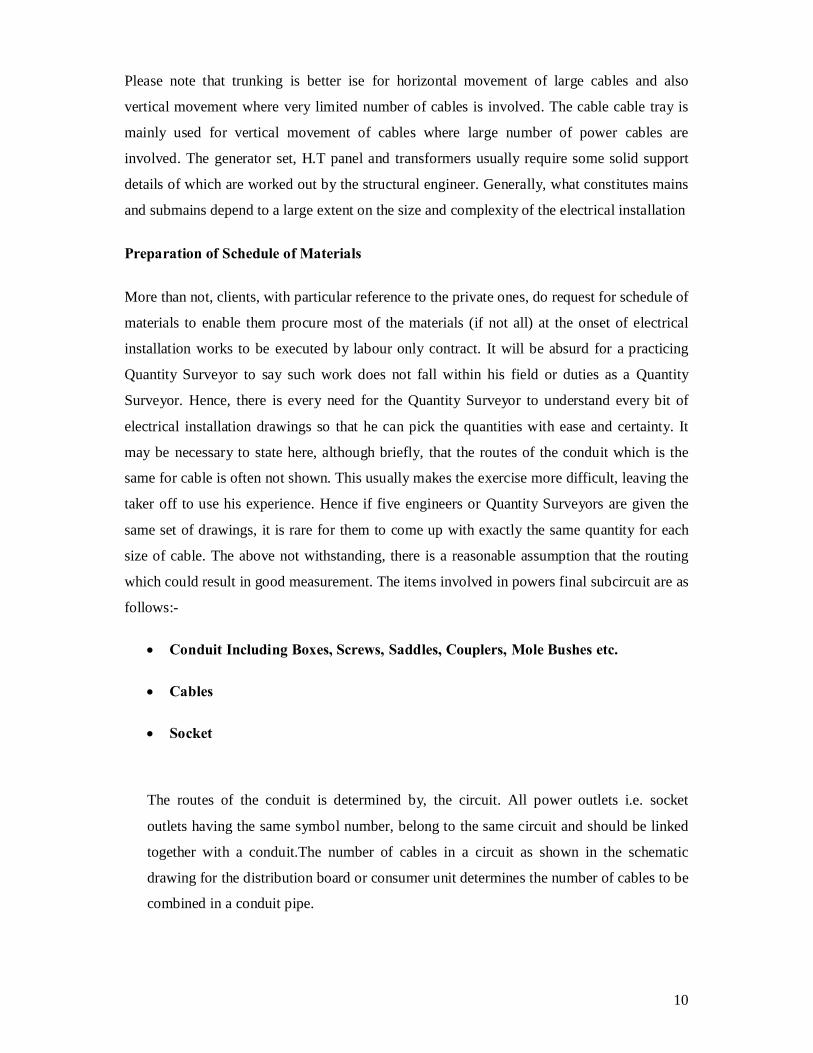
Please note that trunking is better ise for horizontal movement of large cables and also
vertical movement where very limited number of cables is involved. The cable cable tray is
mainly used for vertical movement of cables where large number of power cables are
involved. The generator set, H.T panel and transformers usually require some solid support
details of which are worked out by the structural engineer. Generally, what constitutes mains
and submains depend to a large extent on the size and complexity of the electrical installation
Preparation of Schedule of Materials
More than not, clients, with particular reference to the private ones, do request for schedule of
materials to enable them procure most of the materials (if not all) at the onset of electrical
installation works to be executed by labour only contract. It will be absurd for a practicing
Quantity Surveyor to say such work does not fall within his field or duties as a Quantity
Surveyor. Hence, there is every need for the Quantity Surveyor to understand every bit of
electrical installation drawings so that he can pick the quantities with ease and certainty. It
may be necessary to state here, although briefly, that the routes of the conduit which is the
same for cable is often not shown. This usually makes the exercise more difficult, leaving the
taker off to use his experience. Hence if five engineers or Quantity Surveyors are given the
same set of drawings, it is rare for them to come up with exactly the same quantity for each
size of cable. The above not withstanding, there is a reasonable assumption that the routing
which could result in good measurement. The items involved in powers final subcircuit are as
follows:-
• Conduit Including Boxes, Screws, Saddles, Couplers, Mole Bushes etc.
• Cables
• Socket
The routes of the conduit is determined by, the circuit. All power outlets i.e. socket
outlets having the same symbol number, belong to the same circuit and should be linked
together with a conduit.The number of cables in a circuit as shown in the schematic
drawing for the distribution board or consumer unit determines the number of cables to be
combined in a conduit pipe.
11
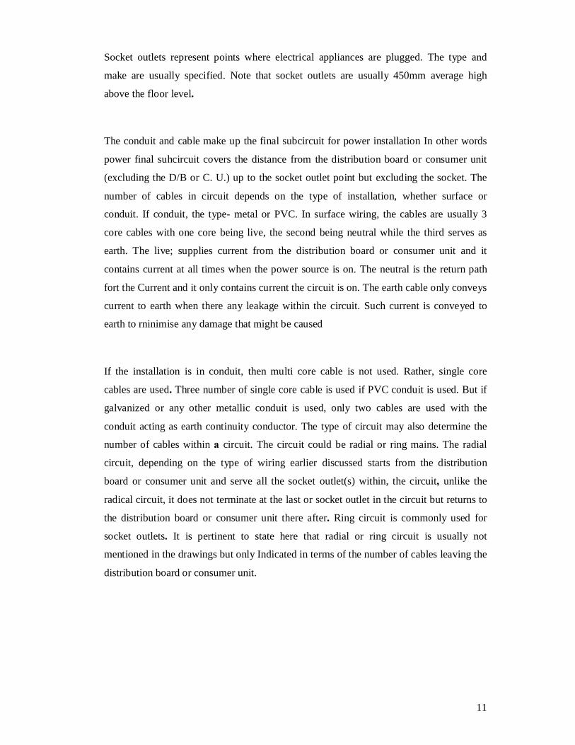
Socket outlets represent points where electrical appliances are plugged. The type and
make are usually specified. Note that socket outlets are usually 450mm average high
above the floor level.
The conduit and cable make up the final subcircuit for power installation In other words
power final suhcircuit covers the distance from the distribution board or consumer unit
(excluding the D/B or C. U.) up to the socket outlet point but excluding the socket. The
number of cables in circuit depends on the type of installation, whether surface or
conduit. If conduit, the type- metal or PVC. In surface wiring, the cables are usually 3
core cables with one core being live, the second being neutral while the third serves as
earth. The live; supplies current from the distribution board or consumer unit and it
contains current at all times when the power source is on. The neutral is the return path
fort the Current and it only contains current the circuit is on. The earth cable only conveys
current to earth when there any leakage within the circuit. Such current is conveyed to
earth to rninimise any damage that might be caused
If the installation is in conduit, then multi core cable is not used. Rather, single core
cables are used. Three number of single core cable is used if PVC conduit is used. But if
galvanized or any other metallic conduit is used, only two cables are used with the
conduit acting as earth continuity conductor. The type of circuit may also determine the
number of cables within a circuit. The circuit could be radial or ring mains. The radial
circuit, depending on the type of wiring earlier discussed starts from the distribution
board or consumer unit and serve all the socket outlet(s) within, the circuit, unlike the
radical circuit, it does not terminate at the last or socket outlet in the circuit but returns to
the distribution board or consumer unit there after. Ring circuit is commonly used for
socket outlets. It is pertinent to state here that radial or ring circuit is usually not
mentioned in the drawings but only Indicated in terms of the number of cables leaving the
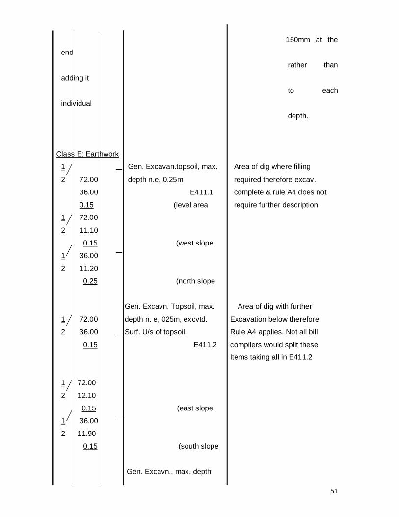
Gen. Excavn. Topsoil, max. Area of dig with further
1 72.00 depth n. e, 025m, excvtd. Excavation below therefore
2 36.00 Surf. U/s of topsoil. Rule A4 applies. Not all bill
0.15 E411.2 compilers would split these
Items taking all in E411.2
1 72.00
2 12.10
0.15 (east slope
1 36.00
2 11.90
0.15 (south slope
Gen. Excavn., max. depth
52
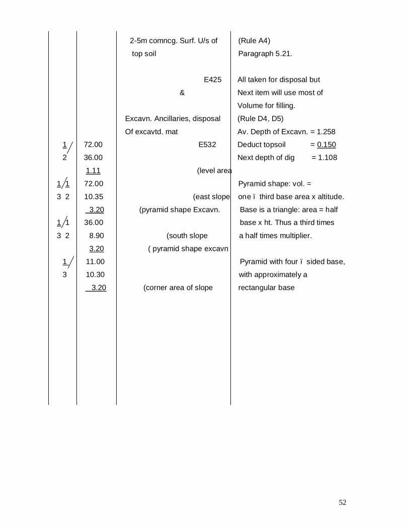
2-5m comncg. Surf. U/s of (Rule A4)
top soil Paragraph 5.21.
E425 All taken for disposal but
& Next item will use most of
Volume for filling.
Excavn. Ancillaries, disposal (Rule D4, D5)
Of excavtd. mat Av. Depth of Excavn. = 1.258
1 72.00 E532 Deduct topsoil = 0.150
2 36.00 Next depth of dig = 1.108
1.11 (level area
1 1 72.00 Pyramid shape: vol. =
3 2 10.35 (east slope one – third base area x altitude.
3.20 (pyramid shape Excavn. Base is a triangle: area = half
1 1 36.00 base x ht. Thus a third times
3 2 8.90 (south slope a half times multiplier.
3.20 ( pyramid shape excavn
1 11.00 Pyramid with four – sided base,
3 10.30 with approximately a
3.20 (corner area of slope rectangular base
53
WEEK 7: 7.0 TAKING OFF IN RESPECT OF MASS CONCRTETE
RETAINING WALL
Introduction This worked example covers the measurement of a simple mass concrete retaining wall.
This example demonstrates the basic requirements of civil engineering standard method
of measurement 3, classes F and G and their application in a piece of construction
55
WEEK 8 Mass Concrete
Retaining Wall
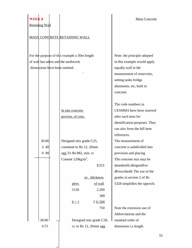
MASS CONCRETE RETAINING WALL
For the purpose of this example a 30m length Note: the principle adopted
of wall has taken and the earthwork in this example would apply
dimensions have been omitted. equally wall to the
` measurement of reservoirs,
setting tanks bridge
abutments, etc, built in
concrete.
The code numbers in
In situ concrete CESMM3 have been inserted
provisn, of conc. after each item for
identification purposes. They
can also form the bill item
references.
30.00 Designed mix grade C25, The measurement of
2. 40 comment to Bs 12, 20mm concrete is aubdivided into
0. 90 agg To Bs 882, min. ct provision and placing
Content 120kg/m3. The concrete mix may be
E253 ‘standard’, ‘dsigned’ or
‘Prescribed’. The use of the
av . thickness grades in section 2 of Bs
plers of wall 5328 simplidies the spproch.
5130 2.200
300
6 + 1 2 l1.500
750 Note the extension use of
Abbreviations and the
30.00 Designed mix grade C30, standard order of
0.75 ct. to Bs 12, 20mm agg. dimension i.e length
56
4.00 to Bs 882, min ct. content breadth and height.
180kg/m3 references can be made in
7/ 0.75 F263 the item description to
0.30 Sampling requirements as a
specification clause .
4.00 (piers pier are taken from both ends
of retaining wall.
Placg. of conc.
30.00 mass bases. Thickness: it is good practice to adopt
2.40 ex. 500 mm. The appropriate standard
0.90 F524 terminology (F52*).
57
1
MASS CONCRETE RETAINING WALL(Contd.)
ht. Of 300-500 th. Wall Note build up of
dimensions
1.200 in ‘waste’.
300 the thickness of wall
900 dertermines the amount of
4.000x _2 = 0.89 tamping or vibrating that
has
9 to be carried out for a
given
av. thickness voume of concrete - this
500 300 affect the price and the
1.200 500 thickness is therefore
2l 1.700 21 800 classify in accordance
with
850` 400 the ranges in the third
ht. of wall ex. 500th. dvision of Class F: the
wall
4.000 has to be subdivided into
the
890 part not exceeding
500mm
3.110 thick and that exceeding
it.
30.00 Mass wall, thickness: Attached piers are
0.40 300-500 mm. included with the wall in
0.89 acordance with rule M3 of
58
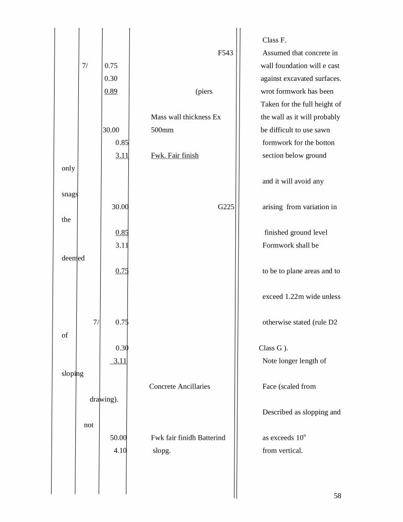
Class F.
F543 Assumed that concrete in
7/ 0.75 wall foundation will e cast
0.30 against excavated surfaces.
0.89 (piers wrot formwork has been
Taken for the full height of
Mass wall thickness Ex the wall as it will probably
30.00 500mm be difficult to use sawn
0.85 formwork for the botton
3.11 Fwk. Fair finish section below ground
only
and it will avoid any
snags
30.00 G225 arising from variation in
the
0.85 finished ground level
3.11 Formwork shall be
deemed
0.75 to be to plane areas and to
exceed 1.22m wide unless
7/ 0.75 otherwise stated (rule D2
of
0.30 Class G ).
3.11 Note longer length of
sloping
Concrete Ancillaries Face (scaled from
drawing).
Described as slopping and
not
50.00 Fwk fair finidh Batterind as exceeds 10o
4.10 slopg. from vertical.
59
Less piers 30.000
7/750 0.250
24.750
Fwk ro finish.
24.75 vert. G145
4.00
7/ 0.75 vert. width 0.4 – 1.22m. The formwork to the faces
0.44 (pier faces and returns of the piers is
G144 kept separate from that to
The wall face, as the narrow
7/2/ 0.30 vert. width 02-0.4m widths generate separate
bill
4.00 (pier retns. items. Both are superficial
G143 Items as they exceed 200
mm
wide.
1.800 l30.000
Measured as inserts in
Inserts accordance with G832.
17/ 1 100 mm clay ware land separate items are not
Drains, 1m lg, cast in on required for adapting
Rake, totally within conc. Formwork, as the inserts are
Vol. G832 not require to be grouted
Into performed openings
(rule M16 of Class G).
Note. If expansion Jointing
was required between the
various sections of wall, the
on-extruding expansion
jinting for the full cross
sectional are would be
60
measured in square metres
with the scrip of sealing
compound on the outer face
of the wall taken as a linear
item.
CLASS E: Earthwork
24.75 granular fill in coetaneous
0.60 pocket behind wall.
0.45 E618
61
WEEK 9: STUDY DRAWINGS AND TAKE OFF BILLING OF ESTATE
62
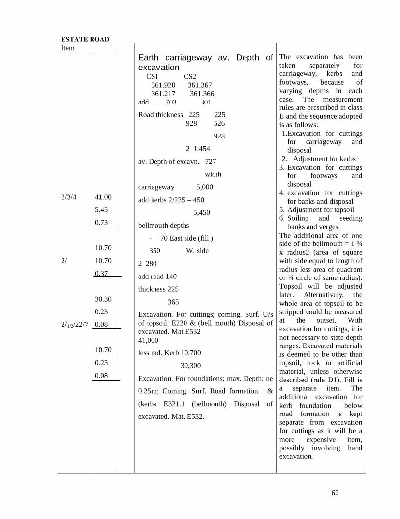
ESTATE ROAD Item
2/3/4
2/
2/1/2/22/7
41.00
5.45
0.73
10.70
10.70
0.37
30.30
0.23
0.08
10.70
0.23
0.08
Earth carriageway av. Depth of excavation
CSI CS2 361.920 361.367 361.217 361.366
add. 703 301
Road thickness 225 225 928 526
928
2 1.454
av. Depth of excavn. 727
width
carriageway 5,000
add kerbs 2/225 = 450
5,450
bellmouth depths
- 70 East side (fill )
350 W. side
2 280
add road 140
thickness 225
365
Excavation. For cuttings; coming. Surf. U/s of topsoil. E220 & (bell mouth) Disposal of excavated. Mat E532 41,000
less rad. Kerb 10,700
30,300
Excavation. For foundations; max. Depth: ne
0.25m; Coming. Surf. Road formation. &
(kerbs E321.1 (bellmouth) Disposal of
excavated. Mat. E532.
The excavation has been taken separately for carriageway, kerbs and footways, because of varying depths in each case. The measurement rules are prescribed in class E and the sequence adopted is as follows: 1.Excavation for cuttings
for carriageway and disposal
2. Adjustment for kerbs 3. Excavation for cuttings
for footways and disposal
4. excavation for cuttings for banks and disposal
5. Adjustment for topsoil 6. Soiling and seeding
banks and verges. The additional area of one side of the bellmouth = 1 ¾ x radius2 (area of square with side equal to length of radius less area of quadrant or ¼ circle of same radius). Topsoil will be adjusted later. Alternatively, the whole area of topsoil to be stripped could be measured at the outset. With excavation for cuttings, it is not necessary to state depth ranges. Excavated materials is deemed to be other than topsoil, rock or artificial material, unless otherwise described (rule D1). Fill is a separate item. The additional excavation for kerb foundation below road formation is kept separate from excavation for cuttings as it will be a more expensive item, possibly involving hand excavation.
63
Item
30.30
3.38
0.94
30.00
3.38
0.17
Footways E. side W.side Av. Depth at CS1 60 900
Add thickness of path or verg 135 195
av. Depth at CS2 – 250 (fill 700 less
thickness of path or verg 135 - 115
(fill – 21.600 = 800
add thickness of path or verge 939 E.
side
CS1 195
CS2 topsoil 150
2345
172
width path 1.500
verge 2.100
3.375
excavn. For cuttings; (W.side commg.
Surf. U/s of topsoil. E220 & (E.side
diaposal of excvtd. Mat. E532
footways at bellmouth E.side W.side
CS2 -250 700
Extremity - 407 543
2-657 2 1.243
-328 622
add thickness of path of verge
135 135
-193 (fill) 757
The fill required under footways and verge on the east side will be made up of non-selected excavated materials. The whole of the area of paths and verges is normally stripped of topsoil, so that some excavation is required even in places which will subsequently receive fill. Excavation forkerbs and backing has already been taken with the carriage way and so needs deducting from the overall width of path and verge. All excavated materials for disposal is taken as material other than topsoil, rock or other hard material in the first instance, and the necessary adjustment will be made later. The depth to surface of paving extreme ends of apths are calculated thus: E. side w. side Channel 360.770 362.170 Lev. Add depth of kerb + ½ fall 137 137 On path 360.907 362.307 Ground lev. At centre of path (interpolated) less finished 360.500 362.850 Level 360.907 362.307 Depth - 407 (fill) .543
64
Item
½ /
½ /
12.60
5.20
0.76
12.60
5.20
0.15
30.30
2.75
1.00
10.00
1.80
0.85
Excavn. For cuttgs commg. Surf. U/s of topsoil E220 paths of bellmouth Disposal of excvtd. E 532 mat. (topsoil on E. side) Width of banks (inc. 150mm additnl. Excavn. For topsoil) E.side W.side
725 850 Excavn. For cuttgs; (w.side commg. Surf. U/s of topsoil E220 & (bellmouth w. side). Disposal of excavated. Mat. E532
The additional 40mm depth
of excavation over the areas
of the two crossings is not
large enough to justify
separate measurement.
Similarly the extra
excavation for quadrants
over that required for kerbs
would be largely offset by
the smaller quantity of
excavation required for the
granite setts- a sense of
proportion must be
maintained .
the build-up dimensions for the bank excavation is inserted in waste, to obtain the average widths and heights. The top soil component will require subsequent adjustment. Disposal of excavated material is deemed to be disposal off the site unless otherwise stated in the item description (rule D4). Slopes of 1 in 2 to banks hove been assumed. The volume of bank excavation = length x average width x average depth.
Filling to enhancements is kept separate from general fill. The description must contain the appropriate third division classification. Adjustment of topsoil excavation over area of carriageway, paths and verges. The depositing and spreading of the of the topsoil will be picked up in subsequent verge and bank slop items. The small surplus quantity of topsoil can remain on the site and make up surface irregularities. The total lengths of verges are adjusted for the lengths of the crossings. The soiling of verges is kept separate from grass seeding. Trimming and preparation deemed included (rule C4)
66
Item
2 3/14/
27.70
2.85
10.00
1.90
27.70
0.65
10.00
1.00
41.00
5.00
10.70
10.70
Fillg. Thickness 150mm, excvtd topsoil; to
surfs. Unclined at an < of 100 to 450 to the
hor. E641.2
&
Landscapg., grass seedg. To surfs. Inclined
at ann < ex. 100 to the hor. E830.2
(E. side) ( bellmth. E. side)
Roads And Pavings Base granular mat. DTP specfd.type 1,
depth: 75mm. R113
&
carriageway slab of (bellmth. DTP
specifd.pavg.qual. conc., depth; 150mm
R414
Two items arise in connection with the banks: 1 soiling of slopes 2 grass seeding. The filling item is measured ion m2 as it is to a stated depth or thickness; stating the appropriate inclination category from rule A14. the grass seeding on banks has a separate classification that of the verges, as it falls into the inclined category under rule A18. Rule C4 states that items for landscaping shall be deemed to include fertilizing, trimming and preparation of surfaces. Thus neither trimming nor preparation is measured where grass seeding applies. However any excavation or filling which receives roads or paving requires preparation to be given as rules M11 and M23. Many details of road construction can be obtained from the department of transport specification for highway works, to which reference can be made in the item descriptions. The actual thickness of slabs and courses should be given instead of the third division depth ranges in accordance with rule A1 of class R.
67
Item
2/3/14
5/
2/
2/
2/1/2/22/7/
41.00
5.00
10.70
10.70
5.00
10.80
4.40
5.00
27.10
10.70
Steel fabric reinft. To BS 4483, nom.
Mass 3-4 kg/m2; type A252. R443
&
waterproof membrane below conc.
Pavement; waterproof paper ot BS 1521
class BIF. R480
&
excavn.ancillaries, prepn.of
excvtd.surfaces. E522
joints in conc.pavements
expansion jts. (transverse depth: 150mm;
as jts. Detail J, drawing (bellmouth.
WE17. (do. Do. R524)
kerbs, channels & edgings less
30.200
setts 2.500
quads.2/300 3.100
27.100
precast conc. Kerb to BS 7263 pt. 12, fig.
1(do), st. or curved to rad.ex. 12m;
bedded and backed w. conc. Grade C10 as
detail X; Dwg We17. R611
precast conc. Kerb to BS 7263 pt. 1,
fig.1(d), curved to rad.n.e. 12m; bedded &
backed a.b. R612.
The waterproof membrane is likely to be of waterproof paper or Impermeable plastic sheeting (250 or 500 grade). Preparation of excavated or filled surfaces to receive permant works is measured under class E (rules M11 and M23). Expansion joints are always measured but construction joints only when they are expressly required (rule M7). No formwork is measured (rule C1). The length of kerb is adjusted in ‘waste’ for the crossings on both sides of the road. The kerb section is identified by reference to BS 7263. kerbs laid to a radius exceeding 12m are included with those laid straight. Details of concrete beds and backings to kerbs are included in the kerb descriptions (rule C3).
68
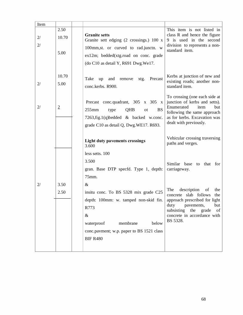
Item
2/
2/
2/
2/
2/
2.50
10.70
5.00
10.70
5.00
2
3.50
2.50
Granite setts Granite sett edging (2 crossings.) 100 x
100mm,st. or curved to rad.junctn. w
ex12m; bedded(xtg.road on conc. grade
(do C10 as detail Y, R691 Dwg.We17.
Take up and remove xtg. Precast
conc.kerbs. R900.
Precast conc.quadrant, 305 x 305 x
255mm type QHB ot BS
7263,fig.1(q)bedded & backed w.conc.
grade C10 as detail Q, Dwg.WE17. R693.
Light duty pavements crossings 3.600
less setts. 100
3.500
gran. Base DTP specfd. Type 1, depth:
75mm.
&
insitu conc. To BS 5328 mix grade C25
depth: 100mm: w. tamped non-skid fin.
R773
&
waterproof membrane below
conc.pavment; w.p. paper to BS 1521 class
BIF R480
This item is not listed in class R and hence the figure 9 is used in the second division to represents a non-standard item. Kerbs at junction of new and existing roads; another non-standard item. To crossing (one each side at junction of kerbs and setts). Enumerated item but following the same approach as for kerbs. Excavation was dealt with previously. Vehicular crossing traversing paths and verges. Similar base to that for carriageway. The description of the concrete slab follows the approach prescribed for light duty pavements, but subsisting the grade of concrete in accordance with BS 5328.
69
Item
2/
2/
2/
2/
2/
2/
3.50
2.50
27.70
1.50
1.98
1.50
12.60
5.20
27.70
10.00
Excavn.ancillaries, prepn. Of excvtd.surfs. E522 Footways 30.200
less crossings. 2.500
27.700
verges crossgs.
Verg 2.100
Less kerb 125
1.975
gran.base,DTP specfd.type 1., depth:
75mm. R713
&
Dense bit.macadam base course DTP
specfd. clause 906,depth: (bellmouth
50mm. R752
&
dense bit.macadam basecourse DTP
specfd. clause 912,depth: (bellmouth
10mm. R751
&
excavn. ancillaries, prepn. Of excvtd.surfs.
E522
edgings
precast conc.edging to BS 7263 PT.1,fig.1 (m) 50 x 150mm; st. or curved to rad.ex.12m, bedded & backed w.conc.grade C10 as detail E.Dwg. WE17. R651.
Each course constitutes a separate item and the particulars are obtained from the department of transport specification of highways works, with the thickness given in each case. Locational notes are given in waste for identification purposes. All preliminary calculations are also inserted to prevent errors and provide the facility for checking. Precast concrete falg description include the types f slab in BS 7263 and the thickness. Precast concrete edging is measured and described in a similar manner to precast concrete kerbs. Figure 1 (m) of BS 7263 shows three sets of dimensions for the round top variety and so dimensions have to be included in the description. First calculate the average depth of the surface water gully connections.
70
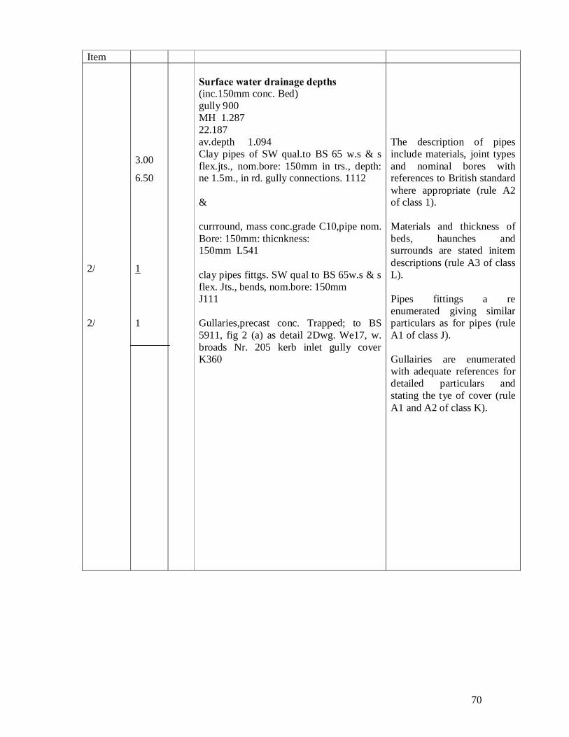
Item
2/
2/
3.00
6.50
1
1
Surface water drainage depths (inc.150mm conc. Bed) gully 900 MH 1.287 22.187 av.depth 1.094 Clay pipes of SW qual.to BS 65 w.s & s flex.jts., nom.bore: 150mm in trs., depth: ne 1.5m., in rd. gully connections. 1112 & currround, mass conc.grade C10,pipe nom. Bore: 150mm: thicnkness: 150mm L541 clay pipes fittgs. SW qual to BS 65w.s & s flex. Jts., bends, nom.bore: 150mm J111 Gullaries,precast conc. Trapped; to BS 5911, fig 2 (a) as detail 2Dwg. We17, w. broads Nr. 205 kerb inlet gully cover K360
The description of pipes include materials, joint types and nominal bores with references to British standard where appropriate (rule A2 of class 1). Materials and thickness of beds, haunches and surrounds are stated initem descriptions (rule A3 of class L). Pipes fittings a re enumerated giving similar particulars as for pipes (rule A1 of class J). Gullairies are enumerated with adequate references for detailed particulars and stating the tye of cover (rule A1 and A2 of class K).
71
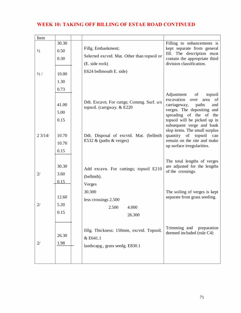
WEEK 10: TAKING OFF BILLING OF ESTAE ROAD CONTINUED
Filling to enhancements is kept separate from general fill. The description must contain the appropriate third division classification. Adjustment of topsoil excavation over area of carriageway, paths and verges. The depositing and spreading of the of the topsoil will be picked up in subsequent verge and bank slop items. The small surplus quantity of topsoil can remain on the site and make up surface irregularities. The total lengths of verges are adjusted for the lengths of the crossings. The soiling of verges is kept separate from grass seeding. Trimming and preparation deemed included (rule C4)
72
Item
2 3/14/
27.70
2.85
10.00
1.90
27.70
0.65
10.00
1.00
41.00
5.00
10.70
10.70
Fillg. Thickness 150mm, excvtd topsoil; to
surfs. Unclined at an < of 100 to 450 to the
hor. E641.2
&
Landscapg., grass seedg. To surfs. Inclined
at ann < ex. 100 to the hor. E830.2
(E. side) ( bellmth. E. side)
Roads And Pavings Base granular mat. DTP specfd.type 1,
depth: 75mm. R113
&
carriageway slab of (bellmth. DTP
specifd.pavg.qual. conc., depth; 150mm
R414
Two items arise in connection with the banks: 1 soiling of slopes 3 grass seeding. The filling item is measured ion m2 as it is to a stated depth or thickness; stating the appropriate inclination category from rule A14. the grass seeding on banks has a separate classification that of the verges, as it falls into the inclined category under rule A18. Rule C4 states that items for landscaping shall be deemed to include fertilizing, trimming and preparation of surfaces. Thus neither trimming nor preparation is measured where grass seeding applies. However any excavation or filling which receives roads or paving requires preparation to be given as rules M11 and M23. Many details of road construction can be obtained from the department of transport specification for highway works, to which reference can be made in the item descriptions. The actual thickness of slabs and courses should be given instead of the third division depth ranges in accordance with rule A1 of class R.
73
Item
2/3/14
5/
2/
2/
2/1/2/22/7/
41.00
5.00
10.70
10.70
5.00
10.80
4.40
5.00
27.10
10.70
Steel fabric reinft. To BS 4483, nom.
Mass 3-4 kg/m2; type A252. R443
&
waterproof membrane below conc.
Pavement; waterproof paper ot BS 1521
class BIF. R480
&
excavn.ancillaries, prepn.of
excvtd.surfaces. E522
joints in conc.pavements
expansion jts. (transverse depth: 150mm;
as jts. Detail J, drawing (bellmouth.
WE17. (do. Do. R524)
kerbs, channels & edgings less
30.200
setts 2.500
quads.2/300 3.100
27.100
precast conc. Kerb to BS 7263 pt. 12, fig.
1(do), st. or curved to rad.ex. 12m;
bedded and backed w. conc. Grade C10 as
detail X; Dwg We17. R611
precast conc. Kerb to BS 7263 pt. 1,
fig.1(d), curved to rad.n.e. 12m; bedded &
backed a.b. R612.
The waterproof membrane is likely to be of waterproof paper or Impermeable plastic sheeting (250 or 500 grade). Preparation of excavated or filled surfaces to receive permant works is measured under class E (rules M11 and M23). Expansion joints are always measured but construction joints only when they are expressly required (rule M7). No formwork is measured (rule C1). The length of kerb is adjusted in ‘waste’ for the crossings on both sides of the road. The kerb section is identified by reference to BS 7263. kerbs laid to a radius exceeding 12m are included with those laid straight. Details of concrete beds and backings to kerbs are included in the kerb descriptions (rule C3).
74
WEEK 11: TAKING OFF FOR ESTATE ROAD (CONTINUED)
Item
2/
2/
2/
2/
2/
2.50
10.70
5.00
10.70
5.00
2
3.50
2.50
Granite setts Granite sett edging (2 crossings.) 100 x
100mm,st. or curved to rad.junctn. w
ex12m; bedded(xtg.road on conc. grade
(do C10 as detail Y, R691 Dwg.We17.
Take up and remove xtg. Precast
conc.kerbs. R900.
Precast conc.quadrant, 305 x 305 x
255mm type QHB ot BS
7263,fig.1(q)bedded & backed w.conc.
grade C10 as detail Q, Dwg.WE17. R693.
Light duty pavements crossings 3.600
less setts. 100
3.500
gran. Base DTP specfd. Type 1, depth:
75mm.
&
insitu conc. To BS 5328 mix grade C25
depth: 100mm: w. tamped non-skid fin.
R773
&
waterproof membrane below
conc.pavment; w.p. paper to BS 1521 class
BIF R480
This item is not listed in class R and hence the figure 9 is used in the second division to represents a non-standard item. Kerbs at junction of new and existing roads; another non-standard item. To crossing (one each side at junction of kerbs and setts). Enumerated item but following the same approach as for kerbs. Excavation was dealt with previously. Vehicular crossing traversing paths and verges. Similar base to that for carriageway. The description of the concrete slab follows the approach prescribed for light duty pavements, but subsisting the grade of concrete in accordance with BS 5328.
75
Item
2/
2/
2/
2/
2/
2/
3.50
2.50
27.70
1.50
1.98
1.50
12.60
5.20
27.70
10.00
Excavn.ancillaries, prepn. Of excvtd.surfs. E522 Footways 30.200
less crossings. 2.500
27.700
verges crossgs.
Verg 2.100
Less kerb 125
1.975
gran.base,DTP specfd.type 1., depth:
75mm. R713
&
Dense bit.macadam base course DTP
specfd. clause 906,depth: (bellmouth
50mm. R752
&
dense bit.macadam basecourse DTP
specfd. clause 912,depth: (bellmouth
10mm. R751
&
excavn. ancillaries, prepn. Of excvtd.surfs.
E522
edgings
precast conc.edging to BS 7263 PT.1,fig.1 (m) 50 x 150mm; st. or curved to rad.ex.12m, bedded & backed w.conc.grade C10 as detail E.Dwg. WE17. R651.
Each course constitutes a separate item and the particulars are obtained from the department of transport specification of highways works, with the thickness given in each case. Locational notes are given in waste for identification purposes. All preliminary calculations are also inserted to prevent errors and provide the facility for checking. Precast concrete falg description include the types f slab in BS 7263 and the thickness. Precast concrete edging is measured and described in a similar manner to precast concrete kerbs. Figure 1 (m) of BS 7263 shows three sets of dimensions for the round top variety and so dimensions have to be included in the description. First calculate the average depth of the surface water gully connections.
76
Item
2/
2/
3.00
6.50
1
1
Surface water drainage depths (inc.150mm conc. Bed) gully 900 MH 1.287 22.187 av.depth 1.094 Clay pipes of SW qual.to BS 65 w.s & s flex.jts., nom.bore: 150mm in trs., depth: ne 1.5m., in rd. gully connections. 1112 & currround, mass conc.grade C10,pipe nom. Bore: 150mm: thicnkness: 150mm L541 clay pipes fittgs. SW qual to BS 65w.s & s flex. Jts., bends, nom.bore: 150mm J111 Gullaries,precast conc. Trapped; to BS 5911, fig 2 (a) as detail 2Dwg. We17, w. broads Nr. 205 kerb inlet gully cover K360
The description of pipes include materials, joint types and nominal bores with references to British standard where appropriate (rule A2 of class 1). Materials and thickness of beds, haunches and surrounds are stated initem descriptions (rule A3 of class L). Pipes fittings a re enumerated giving similar particulars as for pipes (rule A1 of class J). Gullairies are enumerated with adequate references for detailed particulars and stating the tye of cover (rule A1 and A2 of class K).
79
WEEK 13: TAKE OFF FOR PUMPING CHAMBER PUMPING CHAMBER (CONTD) Total depth Excavation for pits and
175 similar structures is measured 3.500 as total depth, but taken in 750 the stages listed in the Third 4.425 Division of class E. Less ht. above grd. 350 it is not considered necessary 4.075 to separate the topsoil for Earth works. Subsequent reuse, because of 30.40 Gen. excatn. Max, depth: the small quantity involved. 3.00 2-5m. 4.08 E425 Separate items are not Required for upholding sides Of excavation or additional Excavn. Ancillaries excavation to provide Working space (rule CI of 3.40 prepn. Of excvtd. Surfs. Class E), but disposal of 3.00 E522 excavated material requires measuring. Note: Preparation of Vertical surfaces not Given as formwork is 3.40 Diposal of excvtd. Mat. Measured, see rule 3.00 E532 M11 in class E. 4.08 In situ concret The provisiob and placing of Concrete are measured Provsn. Of conc. Designed separately as prescribed in Mix grade C30, ct, to BS 12, class E it seens logical to 20mm agg. To BS 882, min. take all cubic provision items 2.80 Ct. content 240kg/m. first folloed by the placing
2.40 F223 items in their various 0.68 area depth categories. Alternatively the Less 3.400 3.000 750 activities could be taken 2/300 600 600 less 75 simutaneously with each st 2.800 2.400 675 Base len. Duplication. 600 900 150 1.650 1.65 Ddt. Ditto 1.20 ( area ard. 0.23 plant fdn.
80
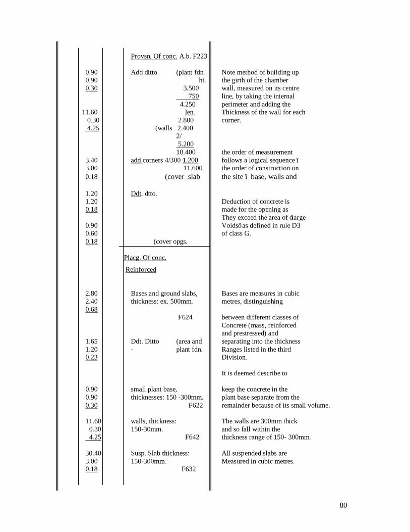
MPING CHAMBER (CONTD) Provsn. Of conc. A.b. F223 0.90 Add ditto. (plant fdn. Note method of building up 0.90 ht. the girth of the chamber 0.30 3.500 wall, measured on its centre 750 line, by taking the internal 4.250 perimeter and adding the 11.60 len. Thickness of the wall for each 0.30 2.800 corner.
4.25 (walls 2.400 2/ 5.200 10.400 the order of measurement 3.40 add corners 4/300 1.200 follows a logical sequence – 3.00 11.600 the order of construction on 0.18 (cover slab the site – base, walls and 1.20 Ddt. dtto. 1.20 Deduction of concrete is 0.18 made for the opening as They exceed the area of ‘large 0.90 Voids’ as defined in rule D3 0.60 of class G. 0.18 (cover opgs.
Placg. Of conc.
Reinforced
2.80 Bases and ground slabs, Bases are measures in cubic 2.40 thickness: ex. 500mm. metres, distinguishing 0.68 F624 between different classes of Concrete (mass, reinforced and prestressed) and 1.65 Ddt. Ditto (area and separating into the thickness 1.20 - plant fdn. Ranges listed in the third 0.23 Division. It is deemed describe to 0.90 small plant base, keep the concrete in the 0.90 thicknesses: 150 -300mm. plant base separate from the 0.30 F622 remainder because of its small volume. 11.60 walls, thickness: The walls are 300mm thick 0.30 150-30mm. and so fall within the 4.25 F642 thickness range of 150- 300mm. 30.40 Susp. Slab thickness: All suspended slabs are 3.00 150-300mm. Measured in cubic metres. 0.18 F632
81
WEEK 14: PUMPING CHAMBER (CONTD) Placg. Of conc. Reinforced 1.20 Ddt. Ditto. F632 same deductions for 1.20 opening as before, as does 0.18 (cover not fall within the inclusion Opgs. Provisions in rule MI of class 0.9 E. 0.60 0.18 Formwork providing rough Conc. Ancillaries and fair finishes must be FWK. Fair fin: 2/1.650 3.300 distinguishes and the plane 1.200 classified in accordance with 4.500 the second division of class 4.50 vert. width: G (horizontal, sloping, 0.23 0.2-0.4m. (Sump battered, vertical and (curved) Widths not exceeding 4/ 0.90 (plant fdn. 200mm are measured as 0.30 G243 linear items and greater Widths in square metres. Conc. Accessories 2.80 Finishg. Of top surfs. Steel To obtain smooth finish to 2.40 trowel. G812 concrete base. 4.50 Finishing. Of formed surfs., To vertical surfaces to sump 0.23 steel trowel. G823 and plant base. 3.60 0.30 Conc. Ancillaries Note build up of external KWK. Ro. Fin girth of pumping station.
82
11.600 Alternatively, the external Add 4/300 1.200 dimensions of the chamber 12.800 could be taken: 3.400 Less pt. 4.250 3.000 Above G.I 225 2/6.400 4.025 12.800 12.80 vertical (ext. face 4.03 of walls Unnecessary to state width G145 as it exceeds 1.22m (rule D2 of class G).
3 PUMPING CHAMBER (CONTD) Fwk. Fair fin. Taking smooth face of 12.80 vertical width ( ext. face concrete to 75mm below 0.23 0.2-0.4m. of walls ground level to allow for any G243 irregularities in the finished 3.500 ground surface. The 75 formwork to the edges of the 3.575 cover slab are taken later. 11.600 Less corners 1.200 10.400 10.40 vertical (int. face wrought formwork to 3.58 of walls internal faces of walls. G245 Conc. Accessories 11.60 finishg. Of top slopg. Surfs, sloping top surfaces to edges 0.30 steel trowel of cover slab. CESMM3 (Class G812 G) does not require the Inclusion of the word Conc. Ancillaries sloping but additional FWK. Fair fin. Information may be given in Accordance with 5.13 where advisable. 2.80 Horizontal G215 Formwork to underside of 2.40 cover slab.
83
1.20 Ddt ditto. Formwork to underside of 1.20 G215 openings deducted as they 0.90 (cover exceed the large void areas 0.60 opgs. Prescribed in rule D3 of class G. 1.200 900 1.200 600 2/ 2.400 2/ 1.500 4.800 3.000 4.80 Vert. widths: (sides of Linear items of formwork as 0.1-0.2m, opgs. Not exceeding 200mm wide. 3.00 G242 The cover slab would be 12.80 Ditto. (Edges of constructed later than the Cover slab walls, after the plant has G242 been installed – hence the Need for a separate 150mm Strip of formwork to the edge of the cover slab. 3
84
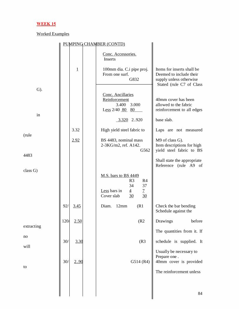
WEEK 15 Worked Examples PUMPING CHAMBER (CONTD) Conc. Accessories. Inserts 1 100mm dia. C.i pipe proj. Items for inserts shall be From one surf. Deemed to include their G832 supply unless otherwise Stated (rule C7 of Class G). Conc. Ancillaries Reinforcement 40mm cover has been 3.400 3.000 allowed to the fabric Less 2/40 80 80 reinforcement to all edges in 3.320 2..920 base slab.
3.32 High yield steel fabric to Laps are not measured (rule 2.92 BS 4483, nominal mass M9 of class G). 2-3KG/m2, ref. A142. Item descriptions for high G562 yield steel fabric to BS 4483 Shall state the appropriate Reference (rule A9 of class G) M.S. bars to BS 4449 R3 R4 34 37 Less bars in 4 7 Cover slab 30 30 92/ 3.45 Diam. 12mm (R1 Check the bar bending Schedule against the 120/ 2.50 (R2 Drawings before extracting The quantities from it. If no 30/ 3.30 (R3 schedule is supplied. It will Usually be necessary to Prepare one . 30/ 2..90 G514 (R4) 40mm cover is provided to The reinforcement unless
85
(walls otherwise specified and the normal allowance for hooked Ends is an addition of 12 4/ 3.30 Diam. 12mm (R3 times the diameter of the bar For each hooked end. The 7/ 2.90 (R4 total length of bar will be Weighted up and billed in 4/ 1.40 (R5 tonnes. Separate items are Not required for supporting Reinforcement (rule CI of class G) 8/ 1.10 Bars exceeding 12m in 10 0.80 Length are given separately (R7 in stages of 3m (rule A7 of 5/ 0.60 (R8 clad G). G514 (Cover slab
5
86
REFERENCES Ivor H. Seeley & George P. Murray (2001)
PALGRAVE Houndmills Basingstoke, Hemisphere
RC2168 & 8 and 175 Fifth Avenue New York.
Ivor H. Seeley (1994) Advanced Measurement of building